EP3502575A1 - Gebäudeheizsystem und verbindungsverfahren - Google Patents
Gebäudeheizsystem und verbindungsverfahren Download PDFInfo
- Publication number
- EP3502575A1 EP3502575A1 EP18397538.2A EP18397538A EP3502575A1 EP 3502575 A1 EP3502575 A1 EP 3502575A1 EP 18397538 A EP18397538 A EP 18397538A EP 3502575 A1 EP3502575 A1 EP 3502575A1
- Authority
- EP
- European Patent Office
- Prior art keywords
- temperature section
- heating
- low temperature
- outlet
- district
- Prior art date
- Legal status (The legal status is an assumption and is not a legal conclusion. Google has not performed a legal analysis and makes no representation as to the accuracy of the status listed.)
- Granted
Links
Images

Classifications
-
- F—MECHANICAL ENGINEERING; LIGHTING; HEATING; WEAPONS; BLASTING
- F24—HEATING; RANGES; VENTILATING
- F24D—DOMESTIC- OR SPACE-HEATING SYSTEMS, e.g. CENTRAL HEATING SYSTEMS; DOMESTIC HOT-WATER SUPPLY SYSTEMS; ELEMENTS OR COMPONENTS THEREFOR
- F24D10/00—District heating systems
-
- F—MECHANICAL ENGINEERING; LIGHTING; HEATING; WEAPONS; BLASTING
- F24—HEATING; RANGES; VENTILATING
- F24D—DOMESTIC- OR SPACE-HEATING SYSTEMS, e.g. CENTRAL HEATING SYSTEMS; DOMESTIC HOT-WATER SUPPLY SYSTEMS; ELEMENTS OR COMPONENTS THEREFOR
- F24D2200/00—Heat sources or energy sources
- F24D2200/13—Heat from a district heating network
-
- Y—GENERAL TAGGING OF NEW TECHNOLOGICAL DEVELOPMENTS; GENERAL TAGGING OF CROSS-SECTIONAL TECHNOLOGIES SPANNING OVER SEVERAL SECTIONS OF THE IPC; TECHNICAL SUBJECTS COVERED BY FORMER USPC CROSS-REFERENCE ART COLLECTIONS [XRACs] AND DIGESTS
- Y02—TECHNOLOGIES OR APPLICATIONS FOR MITIGATION OR ADAPTATION AGAINST CLIMATE CHANGE
- Y02B—CLIMATE CHANGE MITIGATION TECHNOLOGIES RELATED TO BUILDINGS, e.g. HOUSING, HOUSE APPLIANCES OR RELATED END-USER APPLICATIONS
- Y02B30/00—Energy efficient heating, ventilation or air conditioning [HVAC]
- Y02B30/17—District heating
-
- Y—GENERAL TAGGING OF NEW TECHNOLOGICAL DEVELOPMENTS; GENERAL TAGGING OF CROSS-SECTIONAL TECHNOLOGIES SPANNING OVER SEVERAL SECTIONS OF THE IPC; TECHNICAL SUBJECTS COVERED BY FORMER USPC CROSS-REFERENCE ART COLLECTIONS [XRACs] AND DIGESTS
- Y02—TECHNOLOGIES OR APPLICATIONS FOR MITIGATION OR ADAPTATION AGAINST CLIMATE CHANGE
- Y02E—REDUCTION OF GREENHOUSE GAS [GHG] EMISSIONS, RELATED TO ENERGY GENERATION, TRANSMISSION OR DISTRIBUTION
- Y02E20/00—Combustion technologies with mitigation potential
- Y02E20/14—Combined heat and power generation [CHP]
Definitions
- the present invention relates to property heating systems utilizing district heating.
- District heating is the most common heating method in Finland that heats all types of properties energy-efficiently and reliably.
- District heating is supplied to customers through a district heating network with a line, outlet and a return side, i.e. the reverse side.
- the heated sight like a property, is attached to the outlet and reverse side of the heating network in the property's heat distribution center.
- the heat from the water of the district heating network's outlet is transferred through heat exchangers to the property's heat distribution units such as radiators, floor heating networks or air conditioning and hot tap water.
- the cooled water from the heat exchangers returns back to the production plant through the reverse side to be heated again.
- the district heating water does not circulate in the property's heating network. Based on observations in Porvoo in the winter and summer of 2016 the temperature of the water in the district heating network line outlet can vary between 115 to 80°C and in the reverse side between 62,8 to 41 °C.
- the high temperature in the reverse side leads to a poor efficiency in district heating production.
- the high water temperature in the reverse side weakens the efficiency and therefore increases the fuel costs.
- the activity rate / power of the flue gas scrubber increases when the reverse is cooler.
- the invention is characterized by what is stated in the characterizing part of the independent claim.
- the invention is possible to extend the district heating area of the district heating, because the heat energy of both outlet line and the reverse side can be used for heating. In this way, possible overheating of the reverse side can be utilized.
- the invention is suitable for use in a wide variety of heating applications, such as properties which may be new or renovated.
- Utilizing the heat from the reverse side for heating the property also benefits the district heat producers with better efficiency when the reverse is cooler without any technical changes to the power plants.
- the invention enables savings in fuel consumption as the efficiency of scrubbers increases as the reverse side is cooler and returns the sold overheated MWh.
- the entire network heating range is raised with the above mentioned benefits with minor changes.
- the new method can be introduced in new and renovation projects where a new type and possibly cheaper form of heating is desired. Selling energy companies on the reverse side of excess heat would allow a cheaper MWh charge.
- the invention is based on the introduction of two reverse sides and one outlet from a district heating network to a heated site, such as a property.
- One of the reverse lines is used for taking district heating water to the heated site and the other for returning the cooled district heating water to the district heating network.
- Pipes on the reverse side are separate by a distance from each other to prevent mixing. In this way, the heat energy of both the reverse line and the outlet line can be used for the heating needs of the property.
- the expression outlet line and reverse line refer to the pipes or lines on the supply side and on the return side, which are suitable for transferring water or other suitable liquid for transferring heat energy for transferring heat bound to the liquid between the heat production plant and the property or other site to be heated.
- Water or other liquid is transferred from the production plant to the site to be heated, where the liquid cools.
- the cooled liquid is transferred back to the production plant in the return line.
- the property may be a building, such as a house or other building with heated volume and hot water.
- the property is heated by one or more heating devices. Thus, heating the property serves to keep the volume of the property at the desired temperature for maintenance and use of the property, such as housing.
- Hot water is heated by a hot water heating system from where it is transferred to the hot water network of the property.
- the hot water in the hot water network is typically at least 50 - 55 °C, but the temperature can be higher. From the hot water heating system, the water leaving the property's hot water network is generally much higher, for example 65 °C, in order to achieve the aforementioned minimum temperature in the hot water network.
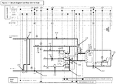
- Figure 1 illustrates a heating system according to one embodiment
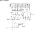
- Figure 2 shows an example of a switching circuit diagram of a distribution center in a heating system according to one embodiment
- Figure 3 illustrates an example of a switching diagram in a distribution center in which an existing distribution center has been upgraded to heating system according to one embodiment.
- the existing distribution center is updated with the necessary parts and is a so-called plug-in solution.
- embodiments of the invention will be described with reference to Figures 1 , 2 and 3 , in which the same reference numerals are used to refer to the same or similar objects.
- the flow directions of the district heating water are illustrated by arrows.
- the heating system may be a heating system for a property or other heated site.
- the heating system may comprise a high temperature section 102 for heating hot water 112 and a low temperature section 104 for heating the property.
- the high temperature section 102 of the heating system is connected to the district heating line 106.
- the outlet 132 of the low temperature section 104 is coupled via a circulating pump 114 to the return heat line 108.
- the return of the low heat section 104 is connected to the return heat line 108 of the district heat at a distance 116 from the outlet 132 of the low temperature section 104.
- outlets of the high temperature section 136 and the low temperature section 132 are connected, as a back-up, to run the district heating water to the low temperature section 104.
- the high temperature section and the low temperature section can be connected by valves 118, such a leveling valves and/or mixing valves.
- the amount of district heating water to be fed from the high temperature section to the low temperature section is controlled by the temperature of the low temperature section 104 outlet 132. If the temperature of the outlet 132 of the low temperature section 104 is below for example 38 °C, the amount of district heating water to be fed from the high temperature section to the low temperature section is increased. If the temperature of the outlet 132 of the low temperature section 104 is higher than for example 38 °C, the amount of district heating water to be fed from the high temperature section is reduced.
- the temperature of the outlet 132 of the low temperature section 104 can be measured by a temperature sensor mounted to measure the temperature at the outlet 132 of the low temperature section 104. Alternatively, another temperature may be set as the threshold temperature instead of the above 38 °C.
- the low temperature section 104 preheats the hot water 110 of the property, and the preheated hot water is heated to its final temperature in the high temperature section.
- sufficient heating water for hot water 112 can be secured throughout the year.
- the energy from the return line can be inadequate for heating water alone.
- the return of the high temperature section 138 is connected through the return of the low temperature section 134 to the return heat line 108 of the district heating.
- both the high temperature section and the low temperature section require only one return.
- the low heat section 104 comprises a heat exchanger for transferring heat from the water from the district heat return line to one or more heating devices of the property.
- the property heating equipment comprises a floor heating system 124, a liquid-circulation radiator system 126, a liquid-circulation ventilation heating cell/radiator system 128.
- the high temperature section 102 comprises a heat exchanger to transfer heat from the water from the district heating outlet line to the hot water 112 of the property.
- the low temperature section outlet 132, high-temperature section 136, low temperature section return 134, and high temperature return 138 are connected to measuring devices 120 for measuring energy consumption, and the heating system comprises one energy reading device 130 for the low temperature section 104 and the high temperature section or separate energy reading devices for the low temperature and high temperature sections.
- a method of heating a property comprising:
- two pipes are brought to the district heating network's reverse side, low temperature section outlet 132 and return 143, and one pipe to the outlet side of the district heating network, high temperature outlet 136.
- One of the reverse side of the pipes forms the heated site's, such as a house's, low-flow for heating the property and preheating the property's tap water 110.
- the hot water 112 of the property can be preheated or heated at low cost to maximize the cooling of the district heating water if the low-flow temperature is high enough for hot water heating.
- district heat from the outlet side can be used to heat warm water 112 as needed and / or to compensate for low-flow as a backup.
- the return pipes are connected to the backbone of the heat network at a certain distance from each other so that they are spaced 116 apart and are not mixed. The return fluid is circulated through the site / property with its own circulation pump.
- the heated site is equipped with heating devices, which may comprise one or more of the following: heating radiator, 35 - 40 °C, low temperature radiator 35 - 40 °C, or floor heating.
- heating devices may comprise one or more of the following: heating radiator, 35 - 40 °C, low temperature radiator 35 - 40 °C, or floor heating.
- the implementation thus enables a complete low heat system to the heated site.
- valve 118 the too low low-flow temperature per connection is increased if necessary by valve 118, for example by leveling/mixing valve, which acts as a security for the low heat system of the property, meaning that the low-flow being too cool to maintain the site's low heat system.
- the low-flow is connected via the circulation pump 114 to the return heat line.
- Low-flow heat and heat from the outlet are measured with measuring devices/sensors 120 readable by a power unit, e.g., MWh or kWh.
- the heating system may comprise a low heat section 104 for heating the property and a high temperature section 102 for heating hot water.
- the low temperature section may be connected to the high temperature section so that the preheating of the hot water takes place in the low temperature section with the heat being transferred and the final heating to the target temperature of the hot water is carried out by the heat being transferred in the high temperature section. In this way, in the combined low temperature section and the high temperature section, the preheated hot water is passed from the low temperature section to the high temperature section.
- the combined return 134 of the low temperature section 104 and the high temperature section 102 is connected to the heat return line 108 within a distance 116 of the district heat from the outlet 132 of the low temperature section 104, and the outlet 136 of the high temperature section 102 and the outlet 132 of the low temperature section are connected to run the district heating water from the high temperature section to the low temperature section.
- the low temperature section 132 is connected to the return heat line 108 of the district heating via the reversing valve 142.
- the reversing valves change direction when the flow direction of the (district heating network) return line 108 of the changes.
- the flows of the reversing valves 142 can be set so that the water from the return heat line 108, "DH LOW TEMPERATURE OUTLET", can receive water for heating the property at low heat section 104, and the water can return to the district heat return line, "DH RETURN", via the combined return 134.
- "DH RETURN” is downstream of the return line of the district heating line "DH LOW TEMPERATURE OUTLET".
- the flows of the reversing valves 142 can be set so that water from the return heat line 108, "DH RETURN”, can receive water to the low heat section 104 and the water can return to the district heat return line, "DH LOW TEMPERATURE OUTLET", via the combined return 134.
- "DH LOW TEMPERATURE OUTLET" is in the downstream flow direction of the district heating return "DH RETURN”.
- the reversing valves 142 may act as indications by the energy company or energy companies as the direction of the network spin changes.
- the invention allows the energy of the site to be heated is divided into two parts. Energy consumption can thus be monitored from low-flow regarding consumed energy and from the district heat outlet regarding consumed energy. In this way, the energy used for low-flow and the energy used in the outlet line can also be differentiated in billing.
- the low-flow and traditional outlet and return data for each heated site can be monitored by measuring devices and be distributed to low-flow and district heat outlet line use.
- the site/property heat distribution center is controlled in a conventional style compared to different parameters. Also, the district heating pipelines and heat exchanger sizes of the site/property should be taken into account, as well as the flows to be adjusted to the needs of the property, such as the traditional district heating connection.
- Shared billing consists of the energy used in low-flow and traditional outlet.
- the low-flow of each site/property as well as the traditional outlet and return data are monitored as before but with shared use.
- the implementation brings significant benefits, including: efficiency of the district heating plant increases and emissions are reduces; the energy company does not need to change their principles or equipment or the pipes; the energy company does not need to invest in pump retention cleaners; the energy company billing heat district in district heating expands and cooling costs become revenue; enables a two-way district heat connection, where the heat/waste heat of the property is sold for use in the return line.
- the invention is suitable for use in real estate and other district heating applications.
Landscapes
- Engineering & Computer Science (AREA)
- Physics & Mathematics (AREA)
- Thermal Sciences (AREA)
- Chemical & Material Sciences (AREA)
- Combustion & Propulsion (AREA)
- Mechanical Engineering (AREA)
- General Engineering & Computer Science (AREA)
- Steam Or Hot-Water Central Heating Systems (AREA)
Priority Applications (1)
| Application Number | Priority Date | Filing Date | Title |
|---|---|---|---|
| PL18397538T PL3502575T3 (pl) | 2017-12-22 | 2018-12-28 | System ogrzewania budynku i sposób podłączenia |
Applications Claiming Priority (1)
| Application Number | Priority Date | Filing Date | Title |
|---|---|---|---|
| FI20176147 | 2017-12-22 |
Publications (2)
| Publication Number | Publication Date |
|---|---|
| EP3502575A1 true EP3502575A1 (de) | 2019-06-26 |
| EP3502575B1 EP3502575B1 (de) | 2020-09-09 |
Family
ID=65199282
Family Applications (1)
| Application Number | Title | Priority Date | Filing Date |
|---|---|---|---|
| EP18397538.2A Active EP3502575B1 (de) | 2017-12-22 | 2018-12-28 | Gebäudeheizsystem und verbindungsverfahren |
Country Status (4)
| Country | Link |
|---|---|
| EP (1) | EP3502575B1 (de) |
| DK (1) | DK3502575T3 (de) |
| LT (1) | LT3502575T (de) |
| PL (1) | PL3502575T3 (de) |
Citations (3)
| Publication number | Priority date | Publication date | Assignee | Title |
|---|---|---|---|---|
| DE102008057908A1 (de) * | 2008-11-18 | 2010-05-20 | Swm Services Gmbh | Wärmeübergabestation mit Kaskade |
| FR3012873A1 (fr) * | 2013-11-04 | 2015-05-08 | Collard & Trolart Thermique | Methode et dispositif de transfert d'energie thermique en milieu urbain |
| US9835385B2 (en) * | 2010-02-03 | 2017-12-05 | Gewofag Gebaeude Service Gmbh | Three-conductor and four-conductor system for saving energy in connection with district heat |
-
2018
- 2018-12-28 PL PL18397538T patent/PL3502575T3/pl unknown
- 2018-12-28 DK DK18397538.2T patent/DK3502575T3/da active
- 2018-12-28 EP EP18397538.2A patent/EP3502575B1/de active Active
- 2018-12-28 LT LTEP18397538.2T patent/LT3502575T/lt unknown
Patent Citations (3)
| Publication number | Priority date | Publication date | Assignee | Title |
|---|---|---|---|---|
| DE102008057908A1 (de) * | 2008-11-18 | 2010-05-20 | Swm Services Gmbh | Wärmeübergabestation mit Kaskade |
| US9835385B2 (en) * | 2010-02-03 | 2017-12-05 | Gewofag Gebaeude Service Gmbh | Three-conductor and four-conductor system for saving energy in connection with district heat |
| FR3012873A1 (fr) * | 2013-11-04 | 2015-05-08 | Collard & Trolart Thermique | Methode et dispositif de transfert d'energie thermique en milieu urbain |
Also Published As
| Publication number | Publication date |
|---|---|
| LT3502575T (lt) | 2020-11-10 |
| EP3502575B1 (de) | 2020-09-09 |
| DK3502575T3 (da) | 2020-11-02 |
| PL3502575T3 (pl) | 2021-01-25 |
Similar Documents
| Publication | Publication Date | Title |
|---|---|---|
| Yang et al. | Evaluations of different domestic hot water preparing methods with ultra-low-temperature district heating | |
| EP3726145B1 (de) | Regionales wärmeenergieverteilungssystem | |
| JP7221337B2 (ja) | 地域熱エネルギー配給システムのための局所熱エネルギー消費器アセンブリおよび局所熱エネルギー発生器アセンブリ | |
| EP3092445B1 (de) | Thermische energienetzwerk | |
| US11454404B2 (en) | Energy distributing system | |
| EP3482137B1 (de) | Kombiniertes heiz- und kühlsystem | |
| EP3593054B1 (de) | Lokale verbraucheranordnung von wärmeenergie und lokale erzeugeranordnung für wärmeenergie für ein regionales wärmeenergieverteilungssystem | |
| US5573183A (en) | Method and apparatus for heating building and ventilation air | |
| EP3482136B1 (de) | Heizsystem | |
| US9835385B2 (en) | Three-conductor and four-conductor system for saving energy in connection with district heat | |
| EP3502575B1 (de) | Gebäudeheizsystem und verbindungsverfahren | |
| US20150060016A1 (en) | Method for pooling thermal energy, and heat exchange loop system between industrial and tertiary sites | |
| JPH04113139A (ja) | 地域冷暖房システム | |
| RS66704B1 (sr) | Sistem za grejanje i hlađenje, odgovarajući postupak i upotreba sistema | |
| FI12357U1 (fi) | Kiinteistön lämmitysjärjestelmä | |
| Rishel et al. | Reducing energy costs with condensing boilers & heat recovery chillers | |
| Broniszewski et al. | Assessment of possibilities for reusing waste heat to cover needs for heating in Bulten Poland SA | |
| CN207350425U (zh) | 一种多级熔融盐供热装置 |
Legal Events
| Date | Code | Title | Description |
|---|---|---|---|
| PUAI | Public reference made under article 153(3) epc to a published international application that has entered the european phase |
Free format text: ORIGINAL CODE: 0009012 |
|
| STAA | Information on the status of an ep patent application or granted ep patent |
Free format text: STATUS: THE APPLICATION HAS BEEN PUBLISHED |
|
| AK | Designated contracting states |
Kind code of ref document: A1 Designated state(s): AL AT BE BG CH CY CZ DE DK EE ES FI FR GB GR HR HU IE IS IT LI LT LU LV MC MK MT NL NO PL PT RO RS SE SI SK SM TR |
|
| AX | Request for extension of the european patent |
Extension state: BA ME |
|
| STAA | Information on the status of an ep patent application or granted ep patent |
Free format text: STATUS: REQUEST FOR EXAMINATION WAS MADE |
|
| 17P | Request for examination filed |
Effective date: 20191219 |
|
| RBV | Designated contracting states (corrected) |
Designated state(s): AL AT BE BG CH CY CZ DE DK EE ES FI FR GB GR HR HU IE IS IT LI LT LU LV MC MK MT NL NO PL PT RO RS SE SI SK SM TR |
|
| GRAP | Despatch of communication of intention to grant a patent |
Free format text: ORIGINAL CODE: EPIDOSNIGR1 |
|
| RIC1 | Information provided on ipc code assigned before grant |
Ipc: F24D 10/00 20060101AFI20200213BHEP |
|
| STAA | Information on the status of an ep patent application or granted ep patent |
Free format text: STATUS: GRANT OF PATENT IS INTENDED |
|
| INTG | Intention to grant announced |
Effective date: 20200319 |
|
| GRAS | Grant fee paid |
Free format text: ORIGINAL CODE: EPIDOSNIGR3 |
|
| GRAA | (expected) grant |
Free format text: ORIGINAL CODE: 0009210 |
|
| STAA | Information on the status of an ep patent application or granted ep patent |
Free format text: STATUS: THE PATENT HAS BEEN GRANTED |
|
| RAP1 | Party data changed (applicant data changed or rights of an application transferred) |
Owner name: IOTOI OY |
|
| RIN1 | Information on inventor provided before grant (corrected) |
Inventor name: ANDERSSON, TOMAS Inventor name: STARCK, NIKLAS Inventor name: SOEDERHOLM, JOHAN |
|
| AK | Designated contracting states |
Kind code of ref document: B1 Designated state(s): AL AT BE BG CH CY CZ DE DK EE ES FI FR GB GR HR HU IE IS IT LI LT LU LV MC MK MT NL NO PL PT RO RS SE SI SK SM TR |
|
| REG | Reference to a national code |
Ref country code: GB Ref legal event code: FG4D |
|
| REG | Reference to a national code |
Ref country code: AT Ref legal event code: REF Ref document number: 1312046 Country of ref document: AT Kind code of ref document: T Effective date: 20200915 Ref country code: CH Ref legal event code: EP |
|
| REG | Reference to a national code |
Ref country code: DE Ref legal event code: R096 Ref document number: 602018007684 Country of ref document: DE |
|
| REG | Reference to a national code |
Ref country code: IE Ref legal event code: FG4D |
|
| REG | Reference to a national code |
Ref country code: DK Ref legal event code: T3 Effective date: 20201026 |
|
| REG | Reference to a national code |
Ref country code: SE Ref legal event code: TRGR |
|
| REG | Reference to a national code |
Ref country code: FI Ref legal event code: FGE |
|
| REG | Reference to a national code |
Ref country code: EE Ref legal event code: FG4A Ref document number: E019974 Country of ref document: EE Effective date: 20201027 |
|
| REG | Reference to a national code |
Ref country code: SK Ref legal event code: T3 Ref document number: E 35811 Country of ref document: SK |
|
| PG25 | Lapsed in a contracting state [announced via postgrant information from national office to epo] |
Ref country code: BG Free format text: LAPSE BECAUSE OF FAILURE TO SUBMIT A TRANSLATION OF THE DESCRIPTION OR TO PAY THE FEE WITHIN THE PRESCRIBED TIME-LIMIT Effective date: 20201209 Ref country code: GR Free format text: LAPSE BECAUSE OF FAILURE TO SUBMIT A TRANSLATION OF THE DESCRIPTION OR TO PAY THE FEE WITHIN THE PRESCRIBED TIME-LIMIT Effective date: 20201210 Ref country code: NO Free format text: LAPSE BECAUSE OF FAILURE TO SUBMIT A TRANSLATION OF THE DESCRIPTION OR TO PAY THE FEE WITHIN THE PRESCRIBED TIME-LIMIT Effective date: 20201209 Ref country code: HR Free format text: LAPSE BECAUSE OF FAILURE TO SUBMIT A TRANSLATION OF THE DESCRIPTION OR TO PAY THE FEE WITHIN THE PRESCRIBED TIME-LIMIT Effective date: 20200909 |
|
| REG | Reference to a national code |
Ref country code: AT Ref legal event code: MK05 Ref document number: 1312046 Country of ref document: AT Kind code of ref document: T Effective date: 20200909 |
|
| REG | Reference to a national code |
Ref country code: NL Ref legal event code: MP Effective date: 20200909 |
|
| PG25 | Lapsed in a contracting state [announced via postgrant information from national office to epo] |
Ref country code: RS Free format text: LAPSE BECAUSE OF FAILURE TO SUBMIT A TRANSLATION OF THE DESCRIPTION OR TO PAY THE FEE WITHIN THE PRESCRIBED TIME-LIMIT Effective date: 20200909 |
|
| PG25 | Lapsed in a contracting state [announced via postgrant information from national office to epo] |
Ref country code: SM Free format text: LAPSE BECAUSE OF FAILURE TO SUBMIT A TRANSLATION OF THE DESCRIPTION OR TO PAY THE FEE WITHIN THE PRESCRIBED TIME-LIMIT Effective date: 20200909 Ref country code: RO Free format text: LAPSE BECAUSE OF FAILURE TO SUBMIT A TRANSLATION OF THE DESCRIPTION OR TO PAY THE FEE WITHIN THE PRESCRIBED TIME-LIMIT Effective date: 20200909 Ref country code: PT Free format text: LAPSE BECAUSE OF FAILURE TO SUBMIT A TRANSLATION OF THE DESCRIPTION OR TO PAY THE FEE WITHIN THE PRESCRIBED TIME-LIMIT Effective date: 20210111 |
|
| REG | Reference to a national code |
Ref country code: EE Ref legal event code: HC1A Ref document number: E019974 Country of ref document: EE |
|
| PG25 | Lapsed in a contracting state [announced via postgrant information from national office to epo] |
Ref country code: IS Free format text: LAPSE BECAUSE OF FAILURE TO SUBMIT A TRANSLATION OF THE DESCRIPTION OR TO PAY THE FEE WITHIN THE PRESCRIBED TIME-LIMIT Effective date: 20210109 Ref country code: ES Free format text: LAPSE BECAUSE OF FAILURE TO SUBMIT A TRANSLATION OF THE DESCRIPTION OR TO PAY THE FEE WITHIN THE PRESCRIBED TIME-LIMIT Effective date: 20200909 Ref country code: AL Free format text: LAPSE BECAUSE OF FAILURE TO SUBMIT A TRANSLATION OF THE DESCRIPTION OR TO PAY THE FEE WITHIN THE PRESCRIBED TIME-LIMIT Effective date: 20200909 Ref country code: AT Free format text: LAPSE BECAUSE OF FAILURE TO SUBMIT A TRANSLATION OF THE DESCRIPTION OR TO PAY THE FEE WITHIN THE PRESCRIBED TIME-LIMIT Effective date: 20200909 |
|
| REG | Reference to a national code |
Ref country code: DE Ref legal event code: R097 Ref document number: 602018007684 Country of ref document: DE |
|
| PLBE | No opposition filed within time limit |
Free format text: ORIGINAL CODE: 0009261 |
|
| STAA | Information on the status of an ep patent application or granted ep patent |
Free format text: STATUS: NO OPPOSITION FILED WITHIN TIME LIMIT |
|
| 26N | No opposition filed |
Effective date: 20210610 |
|
| PG25 | Lapsed in a contracting state [announced via postgrant information from national office to epo] |
Ref country code: SI Free format text: LAPSE BECAUSE OF FAILURE TO SUBMIT A TRANSLATION OF THE DESCRIPTION OR TO PAY THE FEE WITHIN THE PRESCRIBED TIME-LIMIT Effective date: 20200909 Ref country code: MC Free format text: LAPSE BECAUSE OF FAILURE TO SUBMIT A TRANSLATION OF THE DESCRIPTION OR TO PAY THE FEE WITHIN THE PRESCRIBED TIME-LIMIT Effective date: 20200909 |
|
| REG | Reference to a national code |
Ref country code: BE Ref legal event code: MM Effective date: 20201231 |
|
| PG25 | Lapsed in a contracting state [announced via postgrant information from national office to epo] |
Ref country code: IE Free format text: LAPSE BECAUSE OF NON-PAYMENT OF DUE FEES Effective date: 20201228 Ref country code: FR Free format text: LAPSE BECAUSE OF NON-PAYMENT OF DUE FEES Effective date: 20201231 Ref country code: IT Free format text: LAPSE BECAUSE OF FAILURE TO SUBMIT A TRANSLATION OF THE DESCRIPTION OR TO PAY THE FEE WITHIN THE PRESCRIBED TIME-LIMIT Effective date: 20200909 Ref country code: LU Free format text: LAPSE BECAUSE OF NON-PAYMENT OF DUE FEES Effective date: 20201228 |
|
| PG25 | Lapsed in a contracting state [announced via postgrant information from national office to epo] |
Ref country code: TR Free format text: LAPSE BECAUSE OF FAILURE TO SUBMIT A TRANSLATION OF THE DESCRIPTION OR TO PAY THE FEE WITHIN THE PRESCRIBED TIME-LIMIT Effective date: 20200909 Ref country code: MT Free format text: LAPSE BECAUSE OF FAILURE TO SUBMIT A TRANSLATION OF THE DESCRIPTION OR TO PAY THE FEE WITHIN THE PRESCRIBED TIME-LIMIT Effective date: 20200909 Ref country code: CY Free format text: LAPSE BECAUSE OF FAILURE TO SUBMIT A TRANSLATION OF THE DESCRIPTION OR TO PAY THE FEE WITHIN THE PRESCRIBED TIME-LIMIT Effective date: 20200909 |
|
| PG25 | Lapsed in a contracting state [announced via postgrant information from national office to epo] |
Ref country code: MK Free format text: LAPSE BECAUSE OF FAILURE TO SUBMIT A TRANSLATION OF THE DESCRIPTION OR TO PAY THE FEE WITHIN THE PRESCRIBED TIME-LIMIT Effective date: 20200909 |
|
| PG25 | Lapsed in a contracting state [announced via postgrant information from national office to epo] |
Ref country code: BE Free format text: LAPSE BECAUSE OF NON-PAYMENT OF DUE FEES Effective date: 20201231 |
|
| REG | Reference to a national code |
Ref country code: CH Ref legal event code: PL |
|
| PG25 | Lapsed in a contracting state [announced via postgrant information from national office to epo] |
Ref country code: LI Free format text: LAPSE BECAUSE OF NON-PAYMENT OF DUE FEES Effective date: 20211231 Ref country code: CH Free format text: LAPSE BECAUSE OF NON-PAYMENT OF DUE FEES Effective date: 20211231 |
|
| P01 | Opt-out of the competence of the unified patent court (upc) registered |
Effective date: 20230427 |
|
| PG25 | Lapsed in a contracting state [announced via postgrant information from national office to epo] |
Ref country code: NL Free format text: LAPSE BECAUSE OF NON-PAYMENT OF DUE FEES Effective date: 20200923 |
|
| PGFP | Annual fee paid to national office [announced via postgrant information from national office to epo] |
Ref country code: DE Payment date: 20251211 Year of fee payment: 8 |
|
| PGFP | Annual fee paid to national office [announced via postgrant information from national office to epo] |
Ref country code: GB Payment date: 20251121 Year of fee payment: 8 Ref country code: LT Payment date: 20251124 Year of fee payment: 8 |
|
| PGFP | Annual fee paid to national office [announced via postgrant information from national office to epo] |
Ref country code: FI Payment date: 20251208 Year of fee payment: 8 Ref country code: DK Payment date: 20251224 Year of fee payment: 8 |
|
| PGFP | Annual fee paid to national office [announced via postgrant information from national office to epo] |
Ref country code: SE Payment date: 20251219 Year of fee payment: 8 |
|
| PGFP | Annual fee paid to national office [announced via postgrant information from national office to epo] |
Ref country code: CZ Payment date: 20251223 Year of fee payment: 8 |
|
| PGFP | Annual fee paid to national office [announced via postgrant information from national office to epo] |
Ref country code: LV Payment date: 20251218 Year of fee payment: 8 |
|
| PGFP | Annual fee paid to national office [announced via postgrant information from national office to epo] |
Ref country code: PL Payment date: 20251219 Year of fee payment: 8 |
|
| PGFP | Annual fee paid to national office [announced via postgrant information from national office to epo] |
Ref country code: EE Payment date: 20251229 Year of fee payment: 8 |
|
| PGFP | Annual fee paid to national office [announced via postgrant information from national office to epo] |
Ref country code: SK Payment date: 20251223 Year of fee payment: 8 |