EP3502811A1 - Commande d'entraînement à correction d'erreurs autonome des défauts de position - Google Patents
Commande d'entraînement à correction d'erreurs autonome des défauts de position Download PDFInfo
- Publication number
- EP3502811A1 EP3502811A1 EP17209247.0A EP17209247A EP3502811A1 EP 3502811 A1 EP3502811 A1 EP 3502811A1 EP 17209247 A EP17209247 A EP 17209247A EP 3502811 A1 EP3502811 A1 EP 3502811A1
- Authority
- EP
- European Patent Office
- Prior art keywords
- drive control
- rotor shaft
- drive
- imj
- rej
- Prior art date
- Legal status (The legal status is an assumption and is not a legal conclusion. Google has not performed a legal analysis and makes no representation as to the accuracy of the status listed.)
- Withdrawn
Links
Images



Classifications
-
- G—PHYSICS
- G05—CONTROLLING; REGULATING
- G05B—CONTROL OR REGULATING SYSTEMS IN GENERAL; FUNCTIONAL ELEMENTS OF SUCH SYSTEMS; MONITORING OR TESTING ARRANGEMENTS FOR SUCH SYSTEMS OR ELEMENTS
- G05B19/00—Program-control systems
- G05B19/02—Program-control systems electric
- G05B19/18—Numerical control [NC], i.e. automatically operating machines, in particular machine tools, e.g. in a manufacturing environment, so as to execute positioning, movement or co-ordinated operations by means of program data in numerical form
- G05B19/402—Numerical control [NC], i.e. automatically operating machines, in particular machine tools, e.g. in a manufacturing environment, so as to execute positioning, movement or co-ordinated operations by means of program data in numerical form characterised by control arrangements for positioning, e.g. centring a tool relative to a hole in the workpiece, additional detection means to correct position
-
- G—PHYSICS
- G05—CONTROLLING; REGULATING
- G05B—CONTROL OR REGULATING SYSTEMS IN GENERAL; FUNCTIONAL ELEMENTS OF SUCH SYSTEMS; MONITORING OR TESTING ARRANGEMENTS FOR SUCH SYSTEMS OR ELEMENTS
- G05B19/00—Program-control systems
- G05B19/02—Program-control systems electric
- G05B19/04—Program control other than numerical control, i.e. in sequence controllers or logic controllers
- G05B19/042—Program control other than numerical control, i.e. in sequence controllers or logic controllers using digital processors
-
- G—PHYSICS
- G05—CONTROLLING; REGULATING
- G05B—CONTROL OR REGULATING SYSTEMS IN GENERAL; FUNCTIONAL ELEMENTS OF SUCH SYSTEMS; MONITORING OR TESTING ARRANGEMENTS FOR SUCH SYSTEMS OR ELEMENTS
- G05B19/00—Program-control systems
- G05B19/02—Program-control systems electric
- G05B19/18—Numerical control [NC], i.e. automatically operating machines, in particular machine tools, e.g. in a manufacturing environment, so as to execute positioning, movement or co-ordinated operations by means of program data in numerical form
- G05B19/404—Numerical control [NC], i.e. automatically operating machines, in particular machine tools, e.g. in a manufacturing environment, so as to execute positioning, movement or co-ordinated operations by means of program data in numerical form characterised by control arrangements for compensation, e.g. for backlash, overshoot, tool offset, tool wear, temperature, machine construction errors, load, inertia
-
- H—ELECTRICITY
- H02—GENERATION; CONVERSION OR DISTRIBUTION OF ELECTRIC POWER
- H02P—CONTROL OR REGULATION OF ELECTRIC MOTORS, ELECTRIC GENERATORS OR DYNAMO-ELECTRIC CONVERTERS; CONTROLLING TRANSFORMERS, REACTORS OR CHOKE COILS
- H02P6/00—Arrangements for controlling synchronous motors or other dynamo-electric motors using electronic commutation dependent on the rotor position; Electronic commutators therefor
-
- H—ELECTRICITY
- H02—GENERATION; CONVERSION OR DISTRIBUTION OF ELECTRIC POWER
- H02P—CONTROL OR REGULATION OF ELECTRIC MOTORS, ELECTRIC GENERATORS OR DYNAMO-ELECTRIC CONVERTERS; CONTROLLING TRANSFORMERS, REACTORS OR CHOKE COILS
- H02P6/00—Arrangements for controlling synchronous motors or other dynamo-electric motors using electronic commutation dependent on the rotor position; Electronic commutators therefor
- H02P6/14—Electronic commutators
- H02P6/16—Circuit arrangements for detecting position
-
- G—PHYSICS
- G05—CONTROLLING; REGULATING
- G05B—CONTROL OR REGULATING SYSTEMS IN GENERAL; FUNCTIONAL ELEMENTS OF SUCH SYSTEMS; MONITORING OR TESTING ARRANGEMENTS FOR SUCH SYSTEMS OR ELEMENTS
- G05B2219/00—Program-control systems
- G05B2219/30—Nc systems
- G05B2219/41—Servomotor, servo controller till figures
- G05B2219/41125—Compensate position as function of phase lag of drive motor
-
- H—ELECTRICITY
- H02—GENERATION; CONVERSION OR DISTRIBUTION OF ELECTRIC POWER
- H02P—CONTROL OR REGULATION OF ELECTRIC MOTORS, ELECTRIC GENERATORS OR DYNAMO-ELECTRIC CONVERTERS; CONTROLLING TRANSFORMERS, REACTORS OR CHOKE COILS
- H02P29/00—Arrangements for regulating or controlling electric motors, appropriate for both AC and DC motors
- H02P29/02—Providing protection against overload without automatic interruption of supply
- H02P29/024—Detecting a fault condition, e.g. short circuit, locked rotor, open circuit or loss of load
- H02P29/0241—Detecting a fault condition, e.g. short circuit, locked rotor, open circuit or loss of load the fault being an overvoltage
Definitions
- the present invention is further based on an electric drive which has a converter, an electrical machine supplied with electrical energy via the converter and a drive controller.
- a position sensor In regulated electrical machines, a position sensor is often attached to the rotor shaft for measuring position or speed. During operation of the electric machine, the position sensor then supplies raw signals, by means of which a respective actual position of the rotor shaft is determined and / or a respective actual rotational speed of the rotor shaft is determined by differentiating the respective actual position. The respective actual position is then used to position control to a desired position or the respective actual speed used for speed control to a target speed.
- the measurement error is periodic to the rotational position of the rotor shaft, i. the actual situation.
- the error exclusively or almost exclusively on a component whose periodicity with the periodicity of the rotational position corresponds (fundamental).
- the error additionally has other components whose periodicity corresponds to an integer multiple of the periodicity of the rotational position (harmonics).
- the first harmonic in which the periodicity of the error corresponds to twice the periodicity of the rotational position, is often important. The errors are particularly unpleasant if the speed is determined from the determined actual position by differentiating. Because of the differentiation, the amplitude of the error increases proportionally with the speed.
- the error is avoided by a correspondingly accurate positioning of the encoder when mounting to the electric machine or at least kept low.
- the error is taken into account by correction variables.
- the present invention relates to the latter approach in which the error takes account of correction quantities.
- the object of the present invention is to provide possibilities by means of which the required correction variables can be determined in a simple and reliable manner.
- the correction quantities can be determined by the drive controller itself without the need for additional components.
- the special operation is maintained only as long as long as the rotor shaft rotates fast enough.
- the drive control therefore preferably checks in each case on the basis of the respective raw signals whether a current rotational speed of the rotor shaft reaches or falls below a minimum rotational speed. Upon reaching or falling below the minimum speed, the drive control terminates the determination and buffering of the green sheets and goes to determine the correction variables.
- This approach is based on the idea that at a sufficiently high speed (ie a speed above the minimum speed) disturbances of the uniform rotation, for example by Nutrastmomente and the like are sufficiently small so that they can be neglected. At a lower speed (ie a speed below the minimum speed), however, such disturbances can cause errors that can not be easily ignored.
- the drive controller models the coasting of the rotor shaft according to a model having a number of model parameters.
- the drive control not only determines the correction quantities but also the model parameters on the basis of the raw sheets determined in the special operation. This can be reduced or avoided in particular by the model as such caused errors.
- the model parameter k0 is determined by the raw layer at the time of starting the powerless operation of the electric machine, the model parameter k1 by the initial speed.
- the model parameters k2, k3, etc. model the gradual coasting as such. Specifically, the model parameter k2 models the delay caused by friction and the like, and the model parameter k3 models the jerk.
- the highest power of time considered in the model is at least the second power of time, ie the acceleration. Otherwise it would be assumed that the speed set once - ie the initial speed - remains constant. Often it is sufficient if the highest power of time considered in the model is the third power of time, ie the jerk. In some cases, however, it may be necessary be, in addition to consider the fourth power of time. A consideration of even higher powers of time is possible, but usually not required.
- ⁇ are the respective actual position
- rej and imj are the correction quantities.
- it may be sufficient to take into account only the simple of the respective raw layer in normal operation ie only the fundamental frequency. If integer multiples of the respective raw layer also have to be taken into account, it is often sufficient to consider only the first harmonic in addition to the fundamental frequency, ie twice the respective raw layer.
- the drive controller preferably determines the correction variables on the basis of an overdetermined equation system, wherein the drive control furthermore determines the correction variables in accordance with a method in which the error squares are minimized. Thereby, the accuracy of the determination of the correction quantities can be increased.
- the drive control is designed as an inventive drive control in an electric drive of the type mentioned.
- An electric drive has an electrical machine 1.
- the electric machine 1 is supplied with electrical energy via a converter 2.
- the inverter 2 is in turn connected to a supply network 3 or the like.
- the converter 2 comprises the control sets for temporarily switching on the supply network 3 to the phases 4 of the electric machine 1.
- the converter 2 is supplied with control signals U * by a drive controller 5, for example in the form of desired phase voltages.
- the control signals U * determines the inverter 2, the associated control of internal semiconductor switching elements 6, for example, IGBTs.
- the internal semiconductor switching elements 6 is in FIG. 1 only one hint. By means of the internal semiconductor switching elements 6, the switching on of the supply network 3 to the phases 4 of the electric machine 1 is realized.
- the converter 2 transmits actual variables U, I back to the drive controller 5.
- the actual variables U, I may be, for example, an intermediate circuit voltage of a DC link upstream of the semiconductor switching elements 6, actual phase voltages and actual phase currents.
- the communication between the converter 2 and the drive control 5 - ie the transmission of the control signals U * and the transmission of the actual variables U, I - is carried out with a current controller clock, which is usually at least 8 kHz, sometimes even at higher values such as 16 kHz or 32 kHz.
- the drive controller 5 is in FIG. 2 shown. It can act as a sole control device for the electric machine 1 in an individual case. In general, the drive control 5, however, as shown in FIG. 1 subordinate to another control device 7.
- CNC numerical control
- MC motion control
- the drive controller 5 receives at least one higher-order desired value from the further control device 7 and transmits at least one higher-order actual value back to the further control device 7.
- the higher-level setpoint is usually a speed setpoint n *. Alternatively, it may also be a position setpoint ⁇ * or a torque setpoint M *.
- the higher-level actual value is usually an actual position value ⁇ .
- the drive control 5 may also be an actual speed value n or a momentary actual value M. It is also possible for the drive control 5 to transmit a plurality of actual values to the further control device 7, for example an actual position value ⁇ and additionally a rotational speed actual value n.
- the communication between the drive controller 5 and the further control device 7 - ie the transmission of the higher-level setpoints and the transmission of the actual values - is carried out with a further power stroke, which is a speed controller clock or a position controller clock or a torque controller clock depending on the nature of the parent setpoint.
- the further working clock is usually at least 8 kHz, sometimes at larger values such as 16 kHz or 32 kHz.
- the further power stroke is maximum as big as the current controller clock.
- the further duty cycle may be, for example, 8 kHz or 16 kHz, but not 32 kHz.
- the actual position ⁇ - hereinafter also referred to as actual position ⁇ - corresponds to the instantaneous rotational position of a rotor shaft 8 of the electric machine 1.
- the actual position ⁇ or an actual rotational speed n determined using the actual position ⁇ (ie the rotational speed actual value) is used internally by the drive control 5 to correctly determine the control signals U *.
- a position sensor 9 is present. The position sensor 9 detects encoder signals, for example a so-called sinusoidal signal y and a so-called cosine signal x.
- the position sensor 9 transmits the sinusoidal signal y and the cosinusoidal signal x to the drive control 5 as raw signals x, y, and the drive control 5 determines the green position ⁇ 'therefrom.
- Which of these two approaches is taken is of minor importance in the context of the present invention.
- the mode signal B can only assume the values 0 and 1.
- the steps S4 and S6 can be omitted and can be moved from step S2, if necessary directly to step S5.
- the drive control 5 becomes aware of a higher setpoint value in a step S11.
- the drive controller 5 can receive from the further control device 7 a speed setpoint value n * or reuse the last-received speed setpoint value n *.
- the drive controller 5 receives the raw signal x, y, ⁇ 'from the position sensor 9.
- the step S13 may be configured in various ways.
- the index j can only assume the value 1.
- the index j may be 2. Higher values than 2 are also possible, but usually not required.
- the drive controller 5 determines the actual rotational speed n in a step S14. If the determination is carried out, it takes place using the actual position ⁇ , in particular by temporal differentiation of the actual position ⁇ .
- the drive controller 5 determines, for example based on the speed setpoint n * and the actual speed n or the position setpoint ⁇ * and the associated actual position ⁇ , the associated control signals U * for the inverter 2 and outputs them to the inverter 2. If necessary, the drive controller 5 further transmits the actual position ⁇ or another variable, for example the actual rotational speed n, to the further control device 7 in a step S16.
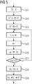
- the drive controller 5 first clears the contents of a buffer memory 10 in a step S21.
- the drive controller 5 determines in a step S22 control signals U * for the converter 2, which cause the rotor shaft 8 to rotate at an initial rotational speed n1.
- the determination of such control signals U * is readily known to those skilled in the art.
- the initial speed n1 is selected to be relatively high, for example, at several 1000 U / min.
- FIG. 6 shows this state in the negative range of the time axis.
- the initial speed n1 is in the example of FIG. 6 scheduled at 6000 rpm. This concrete value of the initial speed n1 is purely exemplary.
- step S23 the drive controller 5 determines in a step S23 other control signals U * for the inverter 2.
- These control signals U * cause the drive controller 5, the electric machine 1 operates powerless.
- the determination of such control signals U * is also known to those skilled in the art.
- the output to switching pulses to the internal semiconductor switches 6 of the inverter 2 can be disabled or the current setpoint for the phases 4 can be set to 0.
- These control signals U * are also output to the inverter 2 in step S23.
- the execution of step S23 will be continued later, i. especially in the course of repeatedly executing the steps S24 to S27. It is also possible to achieve this by making step S23 part of the loop containing steps S24 to S27.
- the rotor shaft 8 Due to the powerless operation of the electric machine 1, the rotor shaft 8 is spinning out.
- the speed n of the rotor shaft 8 thus decreases as shown in FIG. 6 gradually due to friction losses in the bearings of the electric machine 1, or external forces, and be it only the - albeit small - air friction of the rotating rotor shaft 8.
- the reduction of the speed n is carried out over a plurality of complete revolutions of the rotor shaft. 8
- step S24 the drive controller 5 receives raw signals x, y, ⁇ 'from the position sensor 9, respectively.
- step S25 the drive control 5 determines, based on the respective raw signals x, y, ⁇ ', the associated blank position ⁇ '. If the drive control 5 has already accepted the raw layer ⁇ 'as raw signal ⁇ ' in step S25, the determination of the raw layer ⁇ 'is trivial. In this case, step S25 is degenerate.
- step S26 the drive controller 5 stores the green sheet ⁇ 'in the buffer memory 10.
- step S27 the drive controller 5 checks whether the determining and buffering of the green sheets ⁇ 'is to be ended.
- the drive control 5 can determine a current rotational speed n of the rotor shaft 8 on the basis of the respective green position ⁇ 'and check whether the current rotational speed n reaches or falls below a minimum rotational speed n 2.
- the minimum speed n2 may be at a suitable percentage of the initial speed n1, for example anywhere between 60% and 20% of the initial speed n1, in particular between 50% and 30%. According to FIG. 6 For example, the minimum speed n2 is 2000 rpm. If the minimum speed n2 is reached or fallen short of, the determination and buffering of the green sheets ⁇ 'is terminated.
- step S27 it could also be checked in step S27, for example, whether a sufficiently long time has elapsed since the start of the unwinding of the rotor shaft 8. It is also possible, in the context of step S27, to check whether a certain number of complete revolutions of the rotor shaft 8 have taken place since the beginning of the detection of the raw signals x, y, ⁇ ', in particular at least one complete revolution.
- step S28 the drive controller 5 determines at least the correction quantities rej, imj.
- the determination of the correction quantities rej, imj is based on the stored in the buffer memory 10 Rohlagen ⁇ '. In this case, not only a single raw layer ⁇ 'is utilized, but a multiplicity of green sheets ⁇ ' deposited in the buffer storage 10.
- the determined correction quantities rej, imj are stored in a correction quantity memory 11 by the drive control 5 in a step S29.
- the correction quantities rej, imj are therefore available in the following normal operation for the determination of the respective actual position ⁇ .
- the drive controller 5 models the coasting of the rotor shaft 8 according to a model 12.
- t is the time t from the beginning of the powerless operation of the electric machine 1.
- a modeling via an exponential function is also possible.
- the drive controller 5 determines as shown in FIG. 5 in the context of step S28, not only the correction quantities rej, imj but also the model parameters ki. This is readily possible if sufficiently many blank layers ⁇ 'are stored in the buffer memory 10 and are thus available for determining the correction quantities rej, imj and the model parameter ki.
- the drive controller 5 determines the correction quantities rej, imj and possibly also the model parameters ki on the basis of an overdetermined equation system. The determination further preferably takes place in accordance with a method in which the error squares are minimized.
- FIG. 8 shows the solution vector Y for the case where only the correction quantities re1, im1 for the fundamental oscillation are determined and the highest power of the time t considered in the model 12 is the third power, that is to say in addition to the correction quantities re1, im1 the model parameters k0, k1, k2 and k3 are determined.
- FIG. 9 shows the solution vector Y for the case in which, in addition to the correction quantities re1, im1 for the fundamental oscillation, the correction quantities re2, im2 for the first harmonic are also determined and the highest power of the time t considered in the model 12 is the third power.
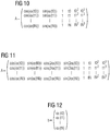
- FIG. 10 shows the matrix A for the case that determines only the correction quantities re1, im1 for the fundamental and the highest power of time t considered in model 12 is the third power.
- FIG. 11 shows the matrix A for the case in which, in addition to the correction quantities re1, im1 for the fundamental oscillation, the correction quantities re2, im2 for the first harmonic are determined and the highest power of the time t considered in the model 12 is the third power.
- tn are the detection times tn at which the respective green sheets ⁇ 'were detected.
- FIG. 12 b is as shown in FIG. 12 a Rohlagen vector.
- the highest power of time t considered in model 12 would be the second power. In this case would be in the in the FIGS. 8 and 9 represented solution vector Y the last component omitted and hereby corresponding to the in the FIGS. 10 and 11 represented matrix A the last column omitted. It would also be possible for the highest power of time t considered in model 12 to be the fourth power. In this case would be in the in the FIGS. 8 and 9 shown solution vector Y additionally as further, in the FIGS. 8 and 9 not shown component of the model parameters k4 occur and hereby corresponding in the in the FIGS. 10 and 11 A further column is added to matrix A shown, in which in each case the fourth power of the detection times tn is entered.
- the present invention has many advantages.
- the determination of the correction quantities rej, imj is possible without any additional hardware.
- a residual error remaining in the actual position ⁇ can be reduced to less than 20% of the error which is present in the respective corresponding blank sheet ⁇ '.
Landscapes
- Engineering & Computer Science (AREA)
- Physics & Mathematics (AREA)
- General Physics & Mathematics (AREA)
- Automation & Control Theory (AREA)
- Human Computer Interaction (AREA)
- Manufacturing & Machinery (AREA)
- Power Engineering (AREA)
- Control Of Ac Motors In General (AREA)
- Control Of Electric Motors In General (AREA)
Priority Applications (5)
| Application Number | Priority Date | Filing Date | Title |
|---|---|---|---|
| EP17209247.0A EP3502811A1 (fr) | 2017-12-21 | 2017-12-21 | Commande d'entraînement à correction d'erreurs autonome des défauts de position |
| US16/955,610 US11726446B2 (en) | 2017-12-21 | 2018-11-19 | Drive controller with self-contained correction function of position errors |
| PCT/EP2018/081739 WO2019120811A1 (fr) | 2017-12-21 | 2018-11-19 | Commande d'entraînement avec correction indépendante d'erreurs de position |
| EP18810944.1A EP3669241B1 (fr) | 2017-12-21 | 2018-11-19 | Commande d'entraînement à correction d'erreurs autonome des défauts de position |
| CN201880082073.6A CN111527457B (zh) | 2017-12-21 | 2018-11-19 | 具有对位置误差独立误差修正的驱动控制器 |
Applications Claiming Priority (1)
| Application Number | Priority Date | Filing Date | Title |
|---|---|---|---|
| EP17209247.0A EP3502811A1 (fr) | 2017-12-21 | 2017-12-21 | Commande d'entraînement à correction d'erreurs autonome des défauts de position |
Publications (1)
| Publication Number | Publication Date |
|---|---|
| EP3502811A1 true EP3502811A1 (fr) | 2019-06-26 |
Family
ID=60971891
Family Applications (2)
| Application Number | Title | Priority Date | Filing Date |
|---|---|---|---|
| EP17209247.0A Withdrawn EP3502811A1 (fr) | 2017-12-21 | 2017-12-21 | Commande d'entraînement à correction d'erreurs autonome des défauts de position |
| EP18810944.1A Active EP3669241B1 (fr) | 2017-12-21 | 2018-11-19 | Commande d'entraînement à correction d'erreurs autonome des défauts de position |
Family Applications After (1)
| Application Number | Title | Priority Date | Filing Date |
|---|---|---|---|
| EP18810944.1A Active EP3669241B1 (fr) | 2017-12-21 | 2018-11-19 | Commande d'entraînement à correction d'erreurs autonome des défauts de position |
Country Status (4)
| Country | Link |
|---|---|
| US (1) | US11726446B2 (fr) |
| EP (2) | EP3502811A1 (fr) |
| CN (1) | CN111527457B (fr) |
| WO (1) | WO2019120811A1 (fr) |
Families Citing this family (1)
| Publication number | Priority date | Publication date | Assignee | Title |
|---|---|---|---|---|
| EP4718710A1 (fr) | 2024-09-30 | 2026-04-01 | Siemens Aktiengesellschaft | Moto-émetteur avec mémoire pour paramètres de correction, entraînement et commande d'entraînement avec le moto-émetteur |
Citations (1)
| Publication number | Priority date | Publication date | Assignee | Title |
|---|---|---|---|---|
| DE102004050999A1 (de) * | 2003-10-30 | 2005-06-02 | Luk Lamellen Und Kupplungsbau Beteiligungs Kg | EC-Motor und Verfahren zum Betreiben eines solchen |
Family Cites Families (17)
| Publication number | Priority date | Publication date | Assignee | Title |
|---|---|---|---|---|
| JPH04275091A (ja) * | 1991-02-28 | 1992-09-30 | Toshiba Corp | 無整流子電動機の駆動制御装置 |
| US7417386B2 (en) * | 2001-05-22 | 2008-08-26 | Rockwell Automation Technologies, Inc. | Electronic line shaft |
| US6903523B2 (en) * | 2003-06-04 | 2005-06-07 | William A. Peterson | Methods and apparatus for dynamically reconfiguring a pulse width modulation approach |
| US7423396B2 (en) * | 2004-06-11 | 2008-09-09 | International Rectifier Corporation | Hall sensor alignment for BLDC motor |
| DE102005004418B4 (de) * | 2005-01-31 | 2006-11-23 | Samson Aktiengesellschaft | Stellungsregler für einen druckmittelbetriebenen Stellantrieb |
| KR101440740B1 (ko) * | 2005-06-28 | 2014-09-18 | 스트리커 코포레이션 | 모터 로터의 상태를 모니터링하는 센서를 포함하는 동력이 있는 수술 도구용 제어 어셈블리 |
| JP5369410B2 (ja) * | 2007-09-05 | 2013-12-18 | セイコーエプソン株式会社 | 電動機の駆動回路及びこれを備えた機器 |
| WO2010033460A2 (fr) * | 2008-09-16 | 2010-03-25 | Kelsey-Hayes Company | Procédé et appareil de commande de la position d’un moteur électrique |
| JP2010223355A (ja) * | 2009-03-24 | 2010-10-07 | Aisin Aw Co Ltd | シフトバイワイヤ装置 |
| JP5737500B2 (ja) * | 2011-01-31 | 2015-06-17 | 日立オートモティブシステムズ株式会社 | 電動ブレーキ装置 |
| DE102011105854B4 (de) * | 2011-06-03 | 2013-04-11 | Nordex Energy Gmbh | Verfahren zum Betreiben einer Windenergieanlage bei Auftreten eines Netzfehlers sowie eine solche Windenergieanlage |
| KR101220388B1 (ko) * | 2011-08-11 | 2013-01-09 | 현대자동차주식회사 | 전기자동차의 이코노미 주행장치 및 그 제어방법 |
| JP6170065B2 (ja) * | 2011-12-02 | 2017-07-26 | ヘリカル ロボティクス,リミティド ライアビリティ カンパニー | 移動ロボット |
| DE102015208710A1 (de) * | 2015-05-11 | 2016-11-17 | Baumüller Nürnberg GmbH | Verfahren zum Betrieb einer elektrischen Maschine und Antrieb |
| KR20180024007A (ko) * | 2015-08-21 | 2018-03-07 | 무라다기카이가부시끼가이샤 | 이동체 |
| US10482787B2 (en) * | 2017-03-21 | 2019-11-19 | Toyota Motor Engineering & Manufacturing North America, Inc. | Selective presentation of coasting coach indicator for consecutive learned deceleration areas in close proximity |
| ES2921062T3 (es) * | 2018-05-02 | 2022-08-17 | Siemens Mobility GmbH | Vehículo ferroviario con un sistema de accionamiento |
-
2017
- 2017-12-21 EP EP17209247.0A patent/EP3502811A1/fr not_active Withdrawn
-
2018
- 2018-11-19 US US16/955,610 patent/US11726446B2/en active Active
- 2018-11-19 EP EP18810944.1A patent/EP3669241B1/fr active Active
- 2018-11-19 CN CN201880082073.6A patent/CN111527457B/zh active Active
- 2018-11-19 WO PCT/EP2018/081739 patent/WO2019120811A1/fr not_active Ceased
Patent Citations (1)
| Publication number | Priority date | Publication date | Assignee | Title |
|---|---|---|---|---|
| DE102004050999A1 (de) * | 2003-10-30 | 2005-06-02 | Luk Lamellen Und Kupplungsbau Beteiligungs Kg | EC-Motor und Verfahren zum Betreiben eines solchen |
Also Published As
| Publication number | Publication date |
|---|---|
| US11726446B2 (en) | 2023-08-15 |
| US20210072722A1 (en) | 2021-03-11 |
| EP3669241A1 (fr) | 2020-06-24 |
| CN111527457B (zh) | 2023-02-28 |
| CN111527457A (zh) | 2020-08-11 |
| EP3669241B1 (fr) | 2022-01-12 |
| WO2019120811A1 (fr) | 2019-06-27 |
Similar Documents
| Publication | Publication Date | Title |
|---|---|---|
| DE19920975B4 (de) | Elektrisches Servolenksystem | |
| DE102011009935B4 (de) | Verfahren zum Ansteuern eines optimalen Betriebspunktes bei einer Synchronmaschine und eine umrichtergespeiste Synchronmaschine | |
| EP2019482A1 (fr) | Système destiné au calcul de l'emplacement et de la vitesse pour un rotor à aimant permanent d'un moteur électrique | |
| DE202016008654U1 (de) | Umrichter zum Speisen eines elektrisch erregten Motors | |
| DE102013005941A1 (de) | Regelvorrichtung für einen Synchronmotor zum Regeln eines Synchronmotors beim Ausführen eines Energierückgewinnungsbetriebs und zum Anhalten des Synchronmotors bei Ausfall der Energieversorgung | |
| EP0690556B1 (fr) | Reconnaissance de l'arrêt d'un moteur tournant alimenté par un onduleur sans capteur de vitesse, dans le cas d'un redémarrage | |
| EP2447104A1 (fr) | Procédé de commande d'un générateur à champ tournant électrique d'une machine de travail mobile | |
| DE102016008984A1 (de) | Motorsteuervorrichtung, wobei eine Stromregeneration angepasst wird, Steuereinheit für einen Umrichter, Maschinenlernvorrichtung und Verfahren davon | |
| DE112013002987T5 (de) | Variabler Drehmomentwinkel für Elektromotor | |
| DE102009038155A1 (de) | Servomotorsteuergerät | |
| EP3292301B1 (fr) | Procédé pour faire fonctionner une éolienne | |
| DE102011006300A1 (de) | Verfahren und Überwachungseinheit zur Überprüfung von Positionswerten | |
| DE112005001683T5 (de) | Motorsteuereinrichtung | |
| EP3255513A1 (fr) | Procede de surveillance en temps reel de la courbe de puissance et/ou du flux d'energie d'un dispositif d'entrainement et dispositif d'entrainement et programme informatique associe | |
| EP0469177B1 (fr) | Procédé et dispositif pour le redémarrage d'un moteur à induction | |
| EP3669241B1 (fr) | Commande d'entraînement à correction d'erreurs autonome des défauts de position | |
| DE19607688B4 (de) | Verfahren und Vorrichtung zur Erfassung und Diagnose eines anormalen Betriebszustandes in einem Servosteuersystem | |
| EP3014756B1 (fr) | Procédé permettant de détecter une mauvaise position angulaire d'un moteur électrique | |
| EP2568596A1 (fr) | Procédé et unité de traitement destinés à la détermination de la position du rotor d'une machine synchrone en fonction du stator de la machine synchrone | |
| DE102010039689A1 (de) | Vorrichtung zur Ansteuerung einer Leistungsendstufe eines elektrischen Geräts mit Reglerkomponenten | |
| EP3186881B1 (fr) | Procédé et ensemble circuit pour faire fonctionner un moteur pas à pas | |
| EP3825787B1 (fr) | Procédé de régulation rapide de la valeur moyenne d'une grandeur de régulation, support de données avec programme ainsi que régulation de moteur permettant de mettre en oeuvre ledit procédé et moteur d'entraînement doté d'une telle régulation de moteur | |
| DE102020134926A1 (de) | Steuervorrichtung und verfahren zur steuerung einer elektrischen servolenkung | |
| EP0570602A2 (fr) | Procédé de réglage de machines à courants triphasés à déterminaison précise dynamique de ses tensions stators en régime stationnaire | |
| EP3059555A1 (fr) | Procede et dispositif de transmission numérique cyclique d'une valeur de position d'un objet en mouvement à l'aide d'une masse inerte |
Legal Events
| Date | Code | Title | Description |
|---|---|---|---|
| PUAI | Public reference made under article 153(3) epc to a published international application that has entered the european phase |
Free format text: ORIGINAL CODE: 0009012 |
|
| AK | Designated contracting states |
Kind code of ref document: A1 Designated state(s): AL AT BE BG CH CY CZ DE DK EE ES FI FR GB GR HR HU IE IS IT LI LT LU LV MC MK MT NL NO PL PT RO RS SE SI SK SM TR |
|
| AX | Request for extension of the european patent |
Extension state: BA ME |
|
| STAA | Information on the status of an ep patent application or granted ep patent |
Free format text: STATUS: THE APPLICATION IS DEEMED TO BE WITHDRAWN |
|
| 18D | Application deemed to be withdrawn |
Effective date: 20200103 |