EP3503309B1 - Appareil d'installation électrique/électronique - Google Patents
Appareil d'installation électrique/électronique Download PDFInfo
- Publication number
- EP3503309B1 EP3503309B1 EP18203630.1A EP18203630A EP3503309B1 EP 3503309 B1 EP3503309 B1 EP 3503309B1 EP 18203630 A EP18203630 A EP 18203630A EP 3503309 B1 EP3503309 B1 EP 3503309B1
- Authority
- EP
- European Patent Office
- Prior art keywords
- electrical
- fact
- attachment
- accordance
- electronic installation
- Prior art date
- Legal status (The legal status is an assumption and is not a legal conclusion. Google has not performed a legal analysis and makes no representation as to the accuracy of the status listed.)
- Active
Links
Images



Classifications
-
- H—ELECTRICITY
- H01—ELECTRIC ELEMENTS
- H01R—ELECTRICALLY-CONDUCTIVE CONNECTIONS; STRUCTURAL ASSOCIATIONS OF A PLURALITY OF MUTUALLY-INSULATED ELECTRICAL CONNECTING ELEMENTS; COUPLING DEVICES; CURRENT COLLECTORS
- H01R24/00—Two-part coupling devices, or either of their cooperating parts, characterised by their overall structure
- H01R24/38—Two-part coupling devices, or either of their cooperating parts, characterised by their overall structure having concentrically or coaxially arranged contacts
-
- H—ELECTRICITY
- H01—ELECTRIC ELEMENTS
- H01R—ELECTRICALLY-CONDUCTIVE CONNECTIONS; STRUCTURAL ASSOCIATIONS OF A PLURALITY OF MUTUALLY-INSULATED ELECTRICAL CONNECTING ELEMENTS; COUPLING DEVICES; CURRENT COLLECTORS
- H01R12/00—Structural associations of a plurality of mutually-insulated electrical connecting elements, specially adapted for printed circuits, e.g. printed circuit boards [PCB], flat or ribbon cables, or like generally planar structures, e.g. terminal strips, terminal blocks; Coupling devices specially adapted for printed circuits, flat or ribbon cables, or like generally planar structures; Terminals specially adapted for contact with, or insertion into, printed circuits, flat or ribbon cables, or like generally planar structures
- H01R12/70—Coupling devices
- H01R12/71—Coupling devices for rigid printing circuits or like structures
- H01R12/712—Coupling devices for rigid printing circuits or like structures co-operating with the surface of the printed circuit or with a coupling device exclusively provided on the surface of the printed circuit
- H01R12/714—Coupling devices for rigid printing circuits or like structures co-operating with the surface of the printed circuit or with a coupling device exclusively provided on the surface of the printed circuit with contacts abutting directly the printed circuit; Button contacts therefore provided on the printed circuit
-
- H—ELECTRICITY
- H01—ELECTRIC ELEMENTS
- H01R—ELECTRICALLY-CONDUCTIVE CONNECTIONS; STRUCTURAL ASSOCIATIONS OF A PLURALITY OF MUTUALLY-INSULATED ELECTRICAL CONNECTING ELEMENTS; COUPLING DEVICES; CURRENT COLLECTORS
- H01R13/00—Details of coupling devices of the kinds covered by groups H01R12/70 or H01R24/00 - H01R33/00
- H01R13/66—Structural association with built-in electrical component
- H01R13/665—Structural association with built-in electrical component with built-in electronic circuit
- H01R13/6658—Structural association with built-in electrical component with built-in electronic circuit on printed circuit board
-
- H—ELECTRICITY
- H01—ELECTRIC ELEMENTS
- H01R—ELECTRICALLY-CONDUCTIVE CONNECTIONS; STRUCTURAL ASSOCIATIONS OF A PLURALITY OF MUTUALLY-INSULATED ELECTRICAL CONNECTING ELEMENTS; COUPLING DEVICES; CURRENT COLLECTORS
- H01R24/00—Two-part coupling devices, or either of their cooperating parts, characterised by their overall structure
- H01R24/76—Two-part coupling devices, or either of their cooperating parts, characterised by their overall structure with sockets, clips or analogous contacts and secured to apparatus or structure, e.g. to a wall
-
- H—ELECTRICITY
- H02—GENERATION; CONVERSION OR DISTRIBUTION OF ELECTRIC POWER
- H02G—INSTALLATION OF ELECTRIC CABLES OR LINES, OR OF COMBINED OPTICAL AND ELECTRIC CABLES OR LINES
- H02G3/00—Installations of electric cables or lines or protective tubing therefor in or on buildings, equivalent structures or vehicles
- H02G3/02—Details
- H02G3/08—Distribution boxes; Connection or junction boxes
- H02G3/12—Distribution boxes; Connection or junction boxes for flush mounting
-
- H—ELECTRICITY
- H01—ELECTRIC ELEMENTS
- H01R—ELECTRICALLY-CONDUCTIVE CONNECTIONS; STRUCTURAL ASSOCIATIONS OF A PLURALITY OF MUTUALLY-INSULATED ELECTRICAL CONNECTING ELEMENTS; COUPLING DEVICES; CURRENT COLLECTORS
- H01R13/00—Details of coupling devices of the kinds covered by groups H01R12/70 or H01R24/00 - H01R33/00
- H01R13/02—Contact members
- H01R13/22—Contacts for co-operating by abutting
- H01R13/24—Contacts for co-operating by abutting resilient; resiliently-mounted
-
- H—ELECTRICITY
- H01—ELECTRIC ELEMENTS
- H01R—ELECTRICALLY-CONDUCTIVE CONNECTIONS; STRUCTURAL ASSOCIATIONS OF A PLURALITY OF MUTUALLY-INSULATED ELECTRICAL CONNECTING ELEMENTS; COUPLING DEVICES; CURRENT COLLECTORS
- H01R13/00—Details of coupling devices of the kinds covered by groups H01R12/70 or H01R24/00 - H01R33/00
- H01R13/62—Means for facilitating engagement or disengagement of coupling parts or for holding them in engagement
- H01R13/6205—Two-part coupling devices held in engagement by a magnet
-
- H—ELECTRICITY
- H01—ELECTRIC ELEMENTS
- H01R—ELECTRICALLY-CONDUCTIVE CONNECTIONS; STRUCTURAL ASSOCIATIONS OF A PLURALITY OF MUTUALLY-INSULATED ELECTRICAL CONNECTING ELEMENTS; COUPLING DEVICES; CURRENT COLLECTORS
- H01R13/00—Details of coupling devices of the kinds covered by groups H01R12/70 or H01R24/00 - H01R33/00
- H01R13/62—Means for facilitating engagement or disengagement of coupling parts or for holding them in engagement
- H01R13/627—Snap or like fastening
- H01R13/6277—Snap or like fastening comprising annular latching means, e.g. ring snapping in an annular groove
-
- H—ELECTRICITY
- H01—ELECTRIC ELEMENTS
- H01R—ELECTRICALLY-CONDUCTIVE CONNECTIONS; STRUCTURAL ASSOCIATIONS OF A PLURALITY OF MUTUALLY-INSULATED ELECTRICAL CONNECTING ELEMENTS; COUPLING DEVICES; CURRENT COLLECTORS
- H01R39/00—Rotary current collectors, distributors or interrupters
Definitions
- the present invention is based on an electrical / electronic installation device designed according to the preamble of the main claim, which mainly consists of an insert (first functional module) and an attachment (second functional module).
- the invention further relates to an arrangement comprising an electrical / electronic installation device of the aforementioned type and an electrical / electronic device that can be coupled thereto.
- Such electrical / electronic installation devices are often used in connection with an installation system of a building.
- the use (first functional module) of such an installation device is typically designed so that it can be inserted into a commercially available installation box and attached to the associated wall and / or installation box.
- the attachment (second functional module) of such an installation device usually not only forms the visible surface but also has the specific functional components.
- attachments are known that have, for example, an input panel via which this installation device can be operated and / or other connected electrical / electronic devices or connected electrical actuators can be controlled.
- attachments are known which have a display unit or are designed as a data input unit and data output unit, for example as a touchscreen display. In many cases, the attachment has different buttons and / or pictograms for simple identification so that the user can easily operate this installation device.
- an electrical / electronic installation device consisting of an insert and an attachment has become known.
- Several electrical / electronic components and at least one first electrical circuit board are accommodated in the housing of the insert to be accommodated in an installation box (first functional module).
- the back of the insert is provided with connecting elements for connection to an installation system of a building.
- the insert On the front side, the insert has an electrical plug part, which is provided for connecting a second functional module designed as an attachment to be arranged on the wall.
- This attachment has an input panel, via which this installation device and / or other connected electrical / electronic devices or connected electrical actuators can be controlled.
- an electrical installation device corresponding to the preamble of claim 1 is known in which a device that can be coupled can be connected to an installation system via an electrical circuit board which has several sliding tracks arranged concentrically to one another for connecting the electrical device.
- the electrical circuit board is arranged in a housing which is closed on the rear by a separate base piece to be connected to it.
- the circuit board is inserted into the rear of the housing before the base part is mounted.
- This installation device has a holding magnet designed as a ring magnet, which is arranged behind the electrical circuit board by interposing an anti-short circuit element. The holding magnet sits, spaced apart by the anti-short circuit element, in alignment behind the sliding tracks of the electrical circuit board.
- the present invention is based on the object of creating an electrical / electronic installation device consisting of an insert and an attachment, which can not only be implemented with a smaller installation depth, but also the possibility a simple exchange of the printed circuit board carrying the sliding tracks is possible and magnetic influences are reduced by the coupling magnet.
- the invention provides that the second functional module designed as an attachment for coupling electrical / electronic devices has a cylinder-shaped, pot-shaped recess as a coupling device, which enables the mechanical, electrical and data-related coupling.
- the invention is for electrical and data technology Coupling, a second electrical circuit board is provided, which has a plurality of circularly arranged electrical sliding tracks as contact points.
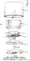
- such an electrical / electronic installation device consists of a first functional module, which is to be accommodated in an installation socket I, is designed as an insert E and has a plurality of electrical / electronic components 2 and at least one first electrical circuit board 3 in its housing 1 is provided with connecting elements 4 for connection to an installation system of a building and on the front with an electrical plug part 5, which is provided for connecting a wall-side, designed as an attachment A, second functional module.
- the second functional module, designed as attachment A has a cylindrical, pot-shaped recess 6 on the front for the releasable coupling of electrical / electronic devices G, in which a second electrical circuit board 8 is arranged, comprising several circularly arranged electrical sliding tracks 7.
- the electrical sliding tracks 7 are electrically conductively connected to the first electrical circuit board 3 arranged in the housing 1 of the insert E via an electrical socket part 9 that can be coupled to the electrical plug part 5 of the insert E.
- the insert E consists mainly of a first electrical circuit board 3 equipped with several electrical / electronic components 2, a housing 1 provided for receiving the first electrical circuit board 3, an intermediate cover 11 to be fixed on the housing 1 and an intermediate cover 11, also on the housing 1 end cover 12 to be defined, which can be equipped with a support plate T.
- the insert E is intended to be accommodated in a commercially available installation socket I.
- the first electrical circuit board 3 is equipped with a plurality of electrical / electronic components 2 necessary for the function.
- the first electrical circuit board 3 has the plug part 5 and the connecting elements 4 via which the connection to an installation system of a building is established.
- the first electrical circuit board 3 also has a power supply unit.
- the electrical plug part 5 located on the first electrical circuit board 3 is designed as a three-pole pin header.
- the support plate T is made of metal and is fixed to the end cover 12 by integrally formed fastening elements.
- a support plate made of plastic which is molded onto the housing 1 or its end cover 12, for example.
- the housing 1 serves to accommodate the first electrical circuit board 3 equipped with the electrical components 2 and is locked at the front by means of the intermediate cover 11 and the end cover 12.
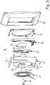
- the attachment A mainly consists of the second electrical circuit board 8, a central piece Z provided with the cylindrical, cup-shaped recess 6 and surrounded by a design frame R, as well as a locking device, a coupling magnet 13 and a cover 14
- the second electrical circuit board 8 is inserted on the front into the first cup-shaped recess 6 of the central piece Z and ultimately comes to rest on the front-side bottom surface 15 of the cylindrical, cup-shaped recess 6.
- the second printed circuit board 8 is held in the interior of the cylindrical, pot-shaped recess 6, resting in the correct position on the bottom surface 15, by means of two locking tabs 10 formed in one piece with the peripheral wall 23 of the cylindrical, pot-shaped recess 6.
- the locking device has a lever arrangement consisting of a first lever 16 and a second lever 17, which are adjustably arranged on the side of the central piece Z facing the insert E.
- a first holding magnet 18 is fastened to the first lever 16 of the lever arrangement and cooperates with a second holding magnet 19 fixed on the side of the central piece Z facing the insert E.
- the central piece Z has, on its side facing the insert E, a receiving pocket 20 in which the coupling magnet 13 is fixed, which cooperates with a counter magnet 21 of an electrical / electronic device G to be coupled.
- the electrical socket part 9 on the attachment A is designed as a three-pole socket strip and is electrically conductive - as already mentioned - in connection with the electrical plug part 5 of the insert E, which is designed as a three-pole pin strip.
- a locking device producing a mechanical operative connection with the coupled electrical / electronic device G is adjustably mounted on the attachment A, the lever arrangement of which consists of a first lever 16 and a second lever 17. The mounting of the two levers 16, 17 is also supported by molded-on elements of the cover 14, which are latched onto the rear side of the central piece Z facing the insert E.
- the first lever 16 is operatively connected to the second lever 17 via a joint arrangement, so that the movements caused on the first lever 16 are transmitted to the second lever 17 via the joint arrangement.
- a knife-like locking element 22 is formed on each of the two levers 16, 17.
- the two locking elements 22 partially reach through the peripheral wall 23 of the cylindrical, cup-shaped recess 6.
- two slot-shaped recesses 24 are formed in the peripheral wall 23.
- the attachment A is attached to the insert E with a screw connection.
- a screw 25 is provided, by means of which the attachment A is screwed onto the insert E, which is provided with a screw socket 26 on the end cover 12 of its housing 1 for this purpose.
- each electrical / electronic device G provided for coupling has a housing arrangement which is provided with a hat-shaped coupling part 27.
- the housing-side coupling part 27 receives a third electrical circuit board 28 in its interior.
- the third electrical circuit board 28 is equipped with six sliding contacts 29 for contacting the three sliding tracks 7 of the second electrical circuit board 8. In each case two sliding contacts 29 are assigned to one of the three sliding tracks 7, so that tapping takes place redundantly via two contact points.
- the counter magnet 21, which interacts with the coupling magnet 13 of the attachment A is accommodated.
- the electrical / electronic devices G to be coupled can have differently designed housing arrangements, in which case different functional components coordinated therewith can be used.
- the electrical / electronic devices G can be designed as lights, loudspeakers, cameras, presence detectors, motion detectors and so on.
- the coupling parts 27 of the electrical / electronic devices G to be coupled are always configured identically.
- the coupling part 27 of the electrical / electronic devices G provided for coupling thus represents a fitting piece for the cup-shaped recess 6 located in the central piece Z of the electrical / electronic installation device Figure 5 is apparent, a circumferentially arranged, groove-shaped recess 30 is made in the outer wall of the hat-shaped coupling part 27, which interacts with the two locking elements 22 of the first lever 16 and the second lever 17 of the locking device located in the attachment A or in the central piece Z of the electrical / electronic installation device.
- An electrical / electronic installation device consisting of an insert E and an attachment A is thus created in a simple manner, the attachment A of which on the front side allows the mechanical, electrical and data-related coupling of many differently designed electrical / electronic devices G via a uniform design Coupling device allows.
Landscapes
- Engineering & Computer Science (AREA)
- Microelectronics & Electronic Packaging (AREA)
- Architecture (AREA)
- Civil Engineering (AREA)
- Structural Engineering (AREA)
- Details Of Connecting Devices For Male And Female Coupling (AREA)
- Casings For Electric Apparatus (AREA)
Claims (18)
- Appareil d'installation électrique/électronique avec un premier module fonctionnel réalisé sous forme d'insert (E), à loger dans un boîtier d'installation, comportant dans son boîtier (1) plusieurs composants électriques/électroniques et au moins une première carte de circuit imprimé et avec un deuxième module fonctionnel réalisé sous forme d'embout (A), lequel premier module fonctionnel est pourvu sur la face arrière d'éléments de raccordement pour le raccordement à un système d'installation d'un bâtiment, dans lequel le deuxième module fonctionnel, conçu comme un embout (A), pour le couplage amovible de dispositifs électriques/électroniques (G) présente sur la face avant un évidement (6) en forme de pot dans lequel est disposée une deuxième carte de circuit imprimé électrique (8) pourvue d'une pluralité de pistes de contact électrique (7) disposées en cercle, et dans lequel le deuxième module fonctionnel, conçu comme un embout (A), présente, sur le côté tourné vers l'insert (E), une poche de réception (20), dans laquelle est fixé un aimant de couplage (13) qui peut coopérer de manière à maintenir avec un contre-aimant (21) d'un dispositif électrique/électronique (G) à coupler, caractérisé en ce que le premier module fonctionnel est muni à l'avant d'une fiche électrique (5), laquelle fiche électrique (5) est prévue pour la connexion au deuxième module fonctionnel à disposer du côté du mur et réalisé sous la forme d'un embout (A), en ce que la deuxième carte de circuit imprimé électrique (8) est insérée à l'avant dans l'évidement en forme de pot (6), et en ce que les bandes de contact électriques (7) sont reliées à une prise électrique (9) prévue sur l'embout (A), qui, par l'intermédiaire de la fiche électrique (5) de l'insert (E), établit les connexions électriques nécessaires au fonctionnement avec la première carte de circuit imprimé électrique (3) située dans le boîtier (1) de l'insert (E), la deuxième carte de circuit imprimé électrique (8) étant de forme annulaire et la surface extérieure de l'aimant de couplage (13) étant espacée de la deuxième carte de circuit imprimé électrique (8) en direction radiale.
- Appareil d'installation électrique/électronique selon la revendication 1, caractérisé en ce que la fiche électrique (5) présente sur l'insert (E) est conçue comme une barrette à broches multipolaire.
- Appareil d'installation électrique/électronique selon l'une des revendications 1 ou 2, caractérisé en ce que la prise électrique (9) présente sur l'embout (A) est conçue comme bande de prises multipolaire.
- Appareil d'installation électrique/électronique selon l'une des revendications 1 à 3, caractérisé en ce qu'un dispositif de verrouillage est prévu sur l'embout (A), qui établit une liaison fonctionnelle mécanique avec le dispositif électrique/électronique couplé (G) et pénètre partiellement dans l'évidement en forme de pot (6) avec au moins un élément de verrouillage (22).
- Appareil d'installation électrique/électronique selon la revendication 4, caractérisé en ce que le dispositif de verrouillage comprend un agencement de levier muni d'éléments de verrouillage (22), qui est monté de manière réglable sur l'embout (A), et en ce que l'agencement de levier est muni d'au moins un premier aimant de maintien (18) pour maintenir la liaison fonctionnelle mécanique, qui est en liaison fonctionnelle avec au moins un deuxième aimant de maintien (19) fixé à l'embout (A).
- Appareil d'installation électrique/électronique selon la revendication 5, caractérisé en ce que l'agencement de levier comprend un premier levier (16) et un second levier (17) couplé de manière mobile au premier levier (16).
- Appareil d'installation électrique/électronique selon l'une des revendications 5 à 6, caractérisé en ce que la liaison fonctionnelle mécanique du dispositif de verrouillage avec le dispositif électrique/électronique couplé (G) peut être annulée par un outil de déverrouillage à alimenter de l'extérieur.
- Appareil d'installation électrique/électronique selon les revendications 5 et 7, caractérisé en ce que l'outil de déclenchement comporte au moins un aimant de déclenchement qui coopère avec l'au moins un premier aimant de maintien (18) présent sur le dispositif de verrouillage pour annuler la liaison fonctionnelle mécanique.
- Appareil d'installation électrique/électronique selon l'une des revendications 1 à 8, caractérisé en ce que l'embout (A) est fixée à l'insert (E) par au moins un raccord à vis.
- Appareil d'installation électrique/électronique selon l'une des revendications 1 à 9, caractérisé en ce qu'une plaque de support (T) est disposée sur le boîtier (1) de l'insert (E) et assure la fixation de l'insert (E) au mur.
- Appareil d'installation électrique/électronique selon la revendication 10, caractérisé en ce que la plaque de support (T) fait partie intégrante du boîtier (1) de l'insert (E).
- Appareil d'installation électrique/électronique selon l'une des revendications 1 à 11, caractérisé en ce que la pièce centrale (Z) de l'embout (A) est maintenue sur l'insert (E) avec interposition d'un cadre de conception (R).
- Appareil d'installation électrique/électronique selon l'une des revendications 1 à 12, caractérisé en ce qu'une unité d'alimentation connectée à la première carte de circuit électrique (3) est logée dans le boîtier (1) de l'insert (E).
- Arrangement comprenant un appareil d'installation électrique/électronique selon l'une des revendications 1 à 13 et un dispositif électrique/électronique (G) pouvant être couplé à celui-ci, caractérisé en ce que qu'au moins un dispositif électrique/électronique (G) pouvant être couplé à l'embout (A) est conçu comme un luminaire.
- Arrangement comprenant un appareil d'installation électrique/électronique selon l'une des revendications 1 à 13 et un dispositif électrique/électronique (G) pouvant être couplé à celui-ci, caractérisé en ce que qu'au moins un dispositif électrique/électronique (G) pouvant être couplé à l'embout (A) est conçu comme un détecteur de movement.
- Arrangement comprenant un appareil d'installation électrique/électronique selon l'une des revendications 1 à 13 et un dispositif électrique/électronique (G) pouvant être couplé à celui-ci, caractérisé en ce que qu'au moins un dispositif électrique/électronique (G) pouvant être couplé à l'embout (A) est conçu comme un détecteur de présence.
- Arrangement comprenant un appareil d'installation électrique/électronique selon l'une des revendications 1 à 13 et un dispositif électrique/électronique (G) pouvant être couplé à celui-ci, caractérisé en ce que qu'au moins un dispositif électrique/électronique (G) qui peut être couplé à l'embout (A) est conçu comme une caméra.
- Arrangement comprenant un appareil d'installation électrique/électronique selon l'une des revendications 1 à 13 et un dispositif électrique/électronique (G) pouvant être couplé à celui-ci, caractérisé en ce que qu'au moins un dispositif électrique/électronique (G) qui peut être couplé à l'embout (A) est conçu comme un haut-parleur.
Applications Claiming Priority (1)
| Application Number | Priority Date | Filing Date | Title |
|---|---|---|---|
| DE102017130675.7A DE102017130675A1 (de) | 2017-12-20 | 2017-12-20 | Elektrisches/elektronisches Installationsgerät |
Publications (2)
| Publication Number | Publication Date |
|---|---|
| EP3503309A1 EP3503309A1 (fr) | 2019-06-26 |
| EP3503309B1 true EP3503309B1 (fr) | 2020-09-30 |
Family
ID=64048881
Family Applications (1)
| Application Number | Title | Priority Date | Filing Date |
|---|---|---|---|
| EP18203630.1A Active EP3503309B1 (fr) | 2017-12-20 | 2018-10-31 | Appareil d'installation électrique/électronique |
Country Status (3)
| Country | Link |
|---|---|
| EP (1) | EP3503309B1 (fr) |
| DE (1) | DE102017130675A1 (fr) |
| ES (1) | ES2840250T3 (fr) |
Cited By (1)
| Publication number | Priority date | Publication date | Assignee | Title |
|---|---|---|---|---|
| DE102021103727B3 (de) | 2021-02-17 | 2021-12-30 | Insta Gmbh | Bedieneinheit für elektrische Geräte der Gebäudesystemtechnik |
Family Cites Families (6)
| Publication number | Priority date | Publication date | Assignee | Title |
|---|---|---|---|---|
| ATE157203T1 (de) * | 1992-10-30 | 1997-09-15 | Contact Gmbh | Elektrische steckverbindung |
| DE102004028546B3 (de) * | 2004-06-12 | 2006-01-12 | Albrecht Jung Gmbh & Co. Kg | Elektrische Steckdose |
| FR2968467B1 (fr) * | 2010-12-01 | 2013-04-12 | Legrand France | Prise de courant et fiche electrique equipees de moyens d'attraction magnetique |
| DE102011111969A1 (de) * | 2011-08-31 | 2013-02-28 | Abb Ag | Unterputz-Schuko-Steckdose |
| DE102015101434B3 (de) | 2015-02-02 | 2016-01-14 | Albrecht Jung Gmbh & Co. Kg | Elektrisches/elektronisches Installationsgerät |
| AU2016262102B2 (en) * | 2015-05-12 | 2021-07-08 | Skyx Platforms Corp. | Smart quick connect device for electrical fixtures |
-
2017
- 2017-12-20 DE DE102017130675.7A patent/DE102017130675A1/de not_active Withdrawn
-
2018
- 2018-10-31 ES ES18203630T patent/ES2840250T3/es active Active
- 2018-10-31 EP EP18203630.1A patent/EP3503309B1/fr active Active
Cited By (2)
| Publication number | Priority date | Publication date | Assignee | Title |
|---|---|---|---|---|
| DE102021103727B3 (de) | 2021-02-17 | 2021-12-30 | Insta Gmbh | Bedieneinheit für elektrische Geräte der Gebäudesystemtechnik |
| EP4047580A1 (fr) | 2021-02-17 | 2022-08-24 | Insta GmbH | Dispositif de commande de dispositifs electriques dans la technique des systemes de batiments |
Also Published As
| Publication number | Publication date |
|---|---|
| DE102017130675A1 (de) | 2019-06-27 |
| EP3503309A1 (fr) | 2019-06-26 |
| ES2840250T3 (es) | 2021-07-06 |
Similar Documents
| Publication | Publication Date | Title |
|---|---|---|
| EP3527886B1 (fr) | Dispositif comprenant un appareil d'instalation électrique/ électronique et un luminiare électrique | |
| EP3503309B1 (fr) | Appareil d'installation électrique/électronique | |
| EP3370489A1 (fr) | Module électronique pour un moteur électrique, en particulier d'un groupe motopompe | |
| EP3799534A1 (fr) | Module fonctionnel | |
| EP4016007B1 (fr) | Appareil d'installation electrique/electronique | |
| DE102009050595B4 (de) | Elektrische Schutzkontaktsteckdose | |
| EP1936757B1 (fr) | Système de connecteur à fiches pour un montage mural | |
| EP2202855A2 (fr) | Appareil d'installation électrique doté d'un moyen de ressort | |
| EP1389810B1 (fr) | Dispositif pour un système électronique de surveillance, en particulier pour un système de surveillance vidéo | |
| EP3503310B1 (fr) | Appareil d'installation électrique/électronique | |
| EP2351176B1 (fr) | Boîte d'installation électrique | |
| EP2348598B1 (fr) | Appareil d'installation encastré électrique pour un appareil audio mobile | |
| EP3751680A1 (fr) | Prise de courant de sécurité commutable à distance | |
| DE102007045869B3 (de) | Elektrisches/elektronisches Installationsgerät | |
| EP2930809B1 (fr) | Appareil d'installation électrique/électronique | |
| DE112018006532T5 (de) | Zusatzgerät für elektrische Schutzvorrichtungen | |
| EP3989687B1 (fr) | Porte-module dans la zone de la protection secondaire contre les explosions | |
| AT516552B1 (de) | Elektrisches Installationsgerät für ein busbasiertes Lichtruf- und/oder Kommunikationssystem | |
| DE19822564C2 (de) | Elektronikgehäuse | |
| EP2453541B1 (fr) | Agencement de commutateurs électriques | |
| EP2315319A1 (fr) | Prise électrique à contact protégé | |
| EP3527885B1 (fr) | Dispositif comprenant un appareil d'installation électrique / électronique et un luminaire électrique | |
| DE102014110652B3 (de) | Elektrisches/elektronisches Installationsgerät | |
| DE102013110460B3 (de) | Elektrisches/elektronisches Installationsgerät | |
| DE102007045871A1 (de) | Elektrisches/elektronisches Installationsgerät |
Legal Events
| Date | Code | Title | Description |
|---|---|---|---|
| PUAI | Public reference made under article 153(3) epc to a published international application that has entered the european phase |
Free format text: ORIGINAL CODE: 0009012 |
|
| STAA | Information on the status of an ep patent application or granted ep patent |
Free format text: STATUS: THE APPLICATION HAS BEEN PUBLISHED |
|
| AK | Designated contracting states |
Kind code of ref document: A1 Designated state(s): AL AT BE BG CH CY CZ DE DK EE ES FI FR GB GR HR HU IE IS IT LI LT LU LV MC MK MT NL NO PL PT RO RS SE SI SK SM TR |
|
| AX | Request for extension of the european patent |
Extension state: BA ME |
|
| STAA | Information on the status of an ep patent application or granted ep patent |
Free format text: STATUS: REQUEST FOR EXAMINATION WAS MADE |
|
| 17P | Request for examination filed |
Effective date: 20190715 |
|
| RBV | Designated contracting states (corrected) |
Designated state(s): AL AT BE BG CH CY CZ DE DK EE ES FI FR GB GR HR HU IE IS IT LI LT LU LV MC MK MT NL NO PL PT RO RS SE SI SK SM TR |
|
| GRAP | Despatch of communication of intention to grant a patent |
Free format text: ORIGINAL CODE: EPIDOSNIGR1 |
|
| STAA | Information on the status of an ep patent application or granted ep patent |
Free format text: STATUS: GRANT OF PATENT IS INTENDED |
|
| RIC1 | Information provided on ipc code assigned before grant |
Ipc: H01R 13/24 20060101ALN20200611BHEP Ipc: H01R 13/62 20060101ALN20200611BHEP Ipc: H02G 3/12 20060101ALI20200611BHEP Ipc: H01R 24/38 20110101AFI20200611BHEP Ipc: H01R 24/76 20110101ALI20200611BHEP Ipc: H01R 39/00 20060101ALN20200611BHEP Ipc: H01R 13/66 20060101ALI20200611BHEP Ipc: H01R 13/627 20060101ALN20200611BHEP Ipc: H01R 12/71 20110101ALI20200611BHEP |
|
| INTG | Intention to grant announced |
Effective date: 20200626 |
|
| GRAS | Grant fee paid |
Free format text: ORIGINAL CODE: EPIDOSNIGR3 |
|
| GRAA | (expected) grant |
Free format text: ORIGINAL CODE: 0009210 |
|
| STAA | Information on the status of an ep patent application or granted ep patent |
Free format text: STATUS: THE PATENT HAS BEEN GRANTED |
|
| AK | Designated contracting states |
Kind code of ref document: B1 Designated state(s): AL AT BE BG CH CY CZ DE DK EE ES FI FR GB GR HR HU IE IS IT LI LT LU LV MC MK MT NL NO PL PT RO RS SE SI SK SM TR |
|
| REG | Reference to a national code |
Ref country code: CH Ref legal event code: EP Ref country code: GB Ref legal event code: FG4D Free format text: NOT ENGLISH |
|
| REG | Reference to a national code |
Ref country code: DE Ref legal event code: R096 Ref document number: 502018002602 Country of ref document: DE Ref country code: AT Ref legal event code: REF Ref document number: 1319758 Country of ref document: AT Kind code of ref document: T Effective date: 20201015 |
|
| REG | Reference to a national code |
Ref country code: IE Ref legal event code: FG4D Free format text: LANGUAGE OF EP DOCUMENT: GERMAN |
|
| REG | Reference to a national code |
Ref country code: NL Ref legal event code: FP |
|
| REG | Reference to a national code |
Ref country code: SE Ref legal event code: TRGR |
|
| PG25 | Lapsed in a contracting state [announced via postgrant information from national office to epo] |
Ref country code: HR Free format text: LAPSE BECAUSE OF FAILURE TO SUBMIT A TRANSLATION OF THE DESCRIPTION OR TO PAY THE FEE WITHIN THE PRESCRIBED TIME-LIMIT Effective date: 20200930 Ref country code: GR Free format text: LAPSE BECAUSE OF FAILURE TO SUBMIT A TRANSLATION OF THE DESCRIPTION OR TO PAY THE FEE WITHIN THE PRESCRIBED TIME-LIMIT Effective date: 20201231 Ref country code: NO Free format text: LAPSE BECAUSE OF FAILURE TO SUBMIT A TRANSLATION OF THE DESCRIPTION OR TO PAY THE FEE WITHIN THE PRESCRIBED TIME-LIMIT Effective date: 20201230 Ref country code: FI Free format text: LAPSE BECAUSE OF FAILURE TO SUBMIT A TRANSLATION OF THE DESCRIPTION OR TO PAY THE FEE WITHIN THE PRESCRIBED TIME-LIMIT Effective date: 20200930 Ref country code: BG Free format text: LAPSE BECAUSE OF FAILURE TO SUBMIT A TRANSLATION OF THE DESCRIPTION OR TO PAY THE FEE WITHIN THE PRESCRIBED TIME-LIMIT Effective date: 20201230 |
|
| PG25 | Lapsed in a contracting state [announced via postgrant information from national office to epo] |
Ref country code: RS Free format text: LAPSE BECAUSE OF FAILURE TO SUBMIT A TRANSLATION OF THE DESCRIPTION OR TO PAY THE FEE WITHIN THE PRESCRIBED TIME-LIMIT Effective date: 20200930 Ref country code: LV Free format text: LAPSE BECAUSE OF FAILURE TO SUBMIT A TRANSLATION OF THE DESCRIPTION OR TO PAY THE FEE WITHIN THE PRESCRIBED TIME-LIMIT Effective date: 20200930 |
|
| REG | Reference to a national code |
Ref country code: LT Ref legal event code: MG4D |
|
| PG25 | Lapsed in a contracting state [announced via postgrant information from national office to epo] |
Ref country code: SM Free format text: LAPSE BECAUSE OF FAILURE TO SUBMIT A TRANSLATION OF THE DESCRIPTION OR TO PAY THE FEE WITHIN THE PRESCRIBED TIME-LIMIT Effective date: 20200930 Ref country code: LT Free format text: LAPSE BECAUSE OF FAILURE TO SUBMIT A TRANSLATION OF THE DESCRIPTION OR TO PAY THE FEE WITHIN THE PRESCRIBED TIME-LIMIT Effective date: 20200930 Ref country code: EE Free format text: LAPSE BECAUSE OF FAILURE TO SUBMIT A TRANSLATION OF THE DESCRIPTION OR TO PAY THE FEE WITHIN THE PRESCRIBED TIME-LIMIT Effective date: 20200930 Ref country code: RO Free format text: LAPSE BECAUSE OF FAILURE TO SUBMIT A TRANSLATION OF THE DESCRIPTION OR TO PAY THE FEE WITHIN THE PRESCRIBED TIME-LIMIT Effective date: 20200930 Ref country code: PT Free format text: LAPSE BECAUSE OF FAILURE TO SUBMIT A TRANSLATION OF THE DESCRIPTION OR TO PAY THE FEE WITHIN THE PRESCRIBED TIME-LIMIT Effective date: 20210201 Ref country code: CZ Free format text: LAPSE BECAUSE OF FAILURE TO SUBMIT A TRANSLATION OF THE DESCRIPTION OR TO PAY THE FEE WITHIN THE PRESCRIBED TIME-LIMIT Effective date: 20200930 |
|
| PG25 | Lapsed in a contracting state [announced via postgrant information from national office to epo] |
Ref country code: IS Free format text: LAPSE BECAUSE OF FAILURE TO SUBMIT A TRANSLATION OF THE DESCRIPTION OR TO PAY THE FEE WITHIN THE PRESCRIBED TIME-LIMIT Effective date: 20210130 Ref country code: PL Free format text: LAPSE BECAUSE OF FAILURE TO SUBMIT A TRANSLATION OF THE DESCRIPTION OR TO PAY THE FEE WITHIN THE PRESCRIBED TIME-LIMIT Effective date: 20200930 Ref country code: AL Free format text: LAPSE BECAUSE OF FAILURE TO SUBMIT A TRANSLATION OF THE DESCRIPTION OR TO PAY THE FEE WITHIN THE PRESCRIBED TIME-LIMIT Effective date: 20200930 |
|
| PG25 | Lapsed in a contracting state [announced via postgrant information from national office to epo] |
Ref country code: LU Free format text: LAPSE BECAUSE OF NON-PAYMENT OF DUE FEES Effective date: 20201031 Ref country code: MC Free format text: LAPSE BECAUSE OF FAILURE TO SUBMIT A TRANSLATION OF THE DESCRIPTION OR TO PAY THE FEE WITHIN THE PRESCRIBED TIME-LIMIT Effective date: 20200930 Ref country code: SK Free format text: LAPSE BECAUSE OF FAILURE TO SUBMIT A TRANSLATION OF THE DESCRIPTION OR TO PAY THE FEE WITHIN THE PRESCRIBED TIME-LIMIT Effective date: 20200930 |
|
| REG | Reference to a national code |
Ref country code: DE Ref legal event code: R097 Ref document number: 502018002602 Country of ref document: DE |
|
| REG | Reference to a national code |
Ref country code: ES Ref legal event code: FG2A Ref document number: 2840250 Country of ref document: ES Kind code of ref document: T3 Effective date: 20210706 |
|
| REG | Reference to a national code |
Ref country code: BE Ref legal event code: MM Effective date: 20201031 |
|
| PLBE | No opposition filed within time limit |
Free format text: ORIGINAL CODE: 0009261 |
|
| STAA | Information on the status of an ep patent application or granted ep patent |
Free format text: STATUS: NO OPPOSITION FILED WITHIN TIME LIMIT |
|
| PG25 | Lapsed in a contracting state [announced via postgrant information from national office to epo] |
Ref country code: DK Free format text: LAPSE BECAUSE OF FAILURE TO SUBMIT A TRANSLATION OF THE DESCRIPTION OR TO PAY THE FEE WITHIN THE PRESCRIBED TIME-LIMIT Effective date: 20200930 Ref country code: BE Free format text: LAPSE BECAUSE OF NON-PAYMENT OF DUE FEES Effective date: 20201031 |
|
| 26N | No opposition filed |
Effective date: 20210701 |
|
| PG25 | Lapsed in a contracting state [announced via postgrant information from national office to epo] |
Ref country code: IE Free format text: LAPSE BECAUSE OF NON-PAYMENT OF DUE FEES Effective date: 20201031 |
|
| PG25 | Lapsed in a contracting state [announced via postgrant information from national office to epo] |
Ref country code: SI Free format text: LAPSE BECAUSE OF FAILURE TO SUBMIT A TRANSLATION OF THE DESCRIPTION OR TO PAY THE FEE WITHIN THE PRESCRIBED TIME-LIMIT Effective date: 20200930 |
|
| REG | Reference to a national code |
Ref country code: CH Ref legal event code: PL |
|
| PG25 | Lapsed in a contracting state [announced via postgrant information from national office to epo] |
Ref country code: IS Free format text: LAPSE BECAUSE OF FAILURE TO SUBMIT A TRANSLATION OF THE DESCRIPTION OR TO PAY THE FEE WITHIN THE PRESCRIBED TIME-LIMIT Effective date: 20210130 Ref country code: TR Free format text: LAPSE BECAUSE OF FAILURE TO SUBMIT A TRANSLATION OF THE DESCRIPTION OR TO PAY THE FEE WITHIN THE PRESCRIBED TIME-LIMIT Effective date: 20200930 Ref country code: MT Free format text: LAPSE BECAUSE OF FAILURE TO SUBMIT A TRANSLATION OF THE DESCRIPTION OR TO PAY THE FEE WITHIN THE PRESCRIBED TIME-LIMIT Effective date: 20200930 Ref country code: CY Free format text: LAPSE BECAUSE OF FAILURE TO SUBMIT A TRANSLATION OF THE DESCRIPTION OR TO PAY THE FEE WITHIN THE PRESCRIBED TIME-LIMIT Effective date: 20200930 |
|
| PG25 | Lapsed in a contracting state [announced via postgrant information from national office to epo] |
Ref country code: MK Free format text: LAPSE BECAUSE OF FAILURE TO SUBMIT A TRANSLATION OF THE DESCRIPTION OR TO PAY THE FEE WITHIN THE PRESCRIBED TIME-LIMIT Effective date: 20200930 |
|
| PG25 | Lapsed in a contracting state [announced via postgrant information from national office to epo] |
Ref country code: LI Free format text: LAPSE BECAUSE OF NON-PAYMENT OF DUE FEES Effective date: 20211031 Ref country code: CH Free format text: LAPSE BECAUSE OF NON-PAYMENT OF DUE FEES Effective date: 20211031 |
|
| GBPC | Gb: european patent ceased through non-payment of renewal fee |
Effective date: 20221031 |
|
| PG25 | Lapsed in a contracting state [announced via postgrant information from national office to epo] |
Ref country code: GB Free format text: LAPSE BECAUSE OF NON-PAYMENT OF DUE FEES Effective date: 20221031 |
|
| PGFP | Annual fee paid to national office [announced via postgrant information from national office to epo] |
Ref country code: IT Payment date: 20250827 Year of fee payment: 8 |
|
| PGFP | Annual fee paid to national office [announced via postgrant information from national office to epo] |
Ref country code: FR Payment date: 20250915 Year of fee payment: 8 |
|
| PGFP | Annual fee paid to national office [announced via postgrant information from national office to epo] |
Ref country code: NL Payment date: 20251020 Year of fee payment: 8 |
|
| PGFP | Annual fee paid to national office [announced via postgrant information from national office to epo] |
Ref country code: DE Payment date: 20250904 Year of fee payment: 8 |
|
| PGFP | Annual fee paid to national office [announced via postgrant information from national office to epo] |
Ref country code: AT Payment date: 20251029 Year of fee payment: 8 |
|
| PGFP | Annual fee paid to national office [announced via postgrant information from national office to epo] |
Ref country code: SE Payment date: 20251106 Year of fee payment: 8 |
|
| PGFP | Annual fee paid to national office [announced via postgrant information from national office to epo] |
Ref country code: ES Payment date: 20251105 Year of fee payment: 8 |