EP3503477A1 - Système et procédé permettant de déterminer la position de n uds dans un système de bus à deux fils - Google Patents
Système et procédé permettant de déterminer la position de n uds dans un système de bus à deux fils Download PDFInfo
- Publication number
- EP3503477A1 EP3503477A1 EP17210237.8A EP17210237A EP3503477A1 EP 3503477 A1 EP3503477 A1 EP 3503477A1 EP 17210237 A EP17210237 A EP 17210237A EP 3503477 A1 EP3503477 A1 EP 3503477A1
- Authority
- EP
- European Patent Office
- Prior art keywords
- node
- nodes
- current
- sinking
- sourcing
- Prior art date
- Legal status (The legal status is an assumption and is not a legal conclusion. Google has not performed a legal analysis and makes no representation as to the accuracy of the status listed.)
- Withdrawn
Links
Images


Classifications
-
- H—ELECTRICITY
- H04—ELECTRIC COMMUNICATION TECHNIQUE
- H04L—TRANSMISSION OF DIGITAL INFORMATION, e.g. TELEGRAPHIC COMMUNICATION
- H04L12/00—Data switching networks
- H04L12/28—Data switching networks characterised by path configuration, e.g. LAN [Local Area Networks] or WAN [Wide Area Networks]
- H04L12/40—Bus networks
- H04L12/40006—Architecture of a communication node
- H04L12/40013—Details regarding a bus controller
-
- H—ELECTRICITY
- H04—ELECTRIC COMMUNICATION TECHNIQUE
- H04L—TRANSMISSION OF DIGITAL INFORMATION, e.g. TELEGRAPHIC COMMUNICATION
- H04L61/00—Network arrangements, protocols or services for addressing or naming
- H04L61/50—Address allocation
- H04L61/5038—Address allocation for local use, e.g. in LAN or USB networks, or in a controller area network [CAN]
-
- H—ELECTRICITY
- H04—ELECTRIC COMMUNICATION TECHNIQUE
- H04L—TRANSMISSION OF DIGITAL INFORMATION, e.g. TELEGRAPHIC COMMUNICATION
- H04L61/00—Network arrangements, protocols or services for addressing or naming
- H04L61/50—Address allocation
- H04L61/5053—Lease time; Renewal aspects
Definitions
- the present invention relates to a two-wire electrical system comprising at least one controller connected to a plurality of nodes. Methods for determining the electrical positions of nodes connected to the two-wire electrical system are provided. Additionally, a system for performing said methods is provided.
- a typical two-wire bus system comprises at least one controller, commonly called a master, and at least one node, also referred to as a slave.
- a master controls at least one controller
- node also referred to as a slave.
- exact knowledge of a node's position in the bus system is essential to performing the system's tasks.
- a log file e.g. a table with node positions.
- Tracking each node's position and (inter)connections in a complex system becomes a difficult, time-consuming and error-prone task.
- the system may require maintenance; for instance when replacing defective nodes or disconnecting obsolete nodes.
- correctly identifying the position of a node and subsequently keeping track of each change in the log file makes maintenance of the bus systems very unreliable and cumbersome.
- a master internal node table may be constructed which contains all of the node IDs and their corresponding (electrical) positions.
- the master internal node table allows the master to know the position and ID of each node in the completed system. The registration of these nodes can be performed manually by labelling of the nodes.
- Each device is provided with a coded label that contains one or more electrical IDs. Accordingly, the coded labels can be scanned whenever a node is connected to the system. However, this is a laborious and time-consuming process and in case of an error (e.g. wrong scan) there is no way for easily determining the location of the error.
- the registration procedure can be done electrically by sequentially connecting each node (i.e. one by one in turn) to an electronic reading device. The position of the scanned or read ID will be related to the position of that node as specified on the physical layout of the two-wire system. This method of connecting nodes is typically performed using a plan, which graphically represents the physical layout of the two-wire bus network.
- An aspect of the invention provides a method for determining the electrical positions of nodes in a two-wire electrical system, the system comprising at least one controller connected to a plurality of nodes, every node comprising a unique ID, the method comprising:
- An aspect of the invention provides a two-wire electrical system, the system comprising:
- An aspect of the invention provides a use of the system according to an embodiment as described herein for performing the method according to an embodiment as described herein; preferably for mining, automotive, automation and machine construction; telecom; data collection.
- the present invention relates to a two-wire electrical system, also referred to as a bus, comprising at least one controller connected to a plurality of nodes; and to methods for determining the positions of nodes in the two-wire electrical system are provided.
- the present invention may provide for a highly effective, fast, cost and/or energy-efficient system for determining the positions of nodes in the two-wire electrical system (i.e. bus wire).
- the present invention may also improve the user-friendliness and reduce the chance of (human or system) errors by enumerating (i.e. automatically detecting) of a node's ID and its corresponding position in the bus wire.
- the present invention may also improve the flexibility of the system by allowing nodes to be connected the bus-wire at any place at any time whilst the bus-wire is powered or unpowered.
- the present invention may also improve the reliability of the system by reducing or preferably altogether preventing invasive interaction with the system, such as cutting of the wires and tagging of the nodes.
- the present invention may also improve the resource cost of the system by reducing or preferably altogether eliminating the need for external elements (e.g. sensors, resistors) to be inserted and/or coupled into the bus.
- the present invention may also decrease the labour intensity of the system by reducing the workload of technicians operating the system and/or performing maintenance in the field.
- the present invention may also improve the efficiency of the system by allowing more nodes to be incorporated over single or multiple wire lengths.
- Controller/node or alternatively master/slave is a model of communication between devices wherein at least one device is being configured to act as a controller (or master) has control over at least one other device configured as node (or slave).
- a master is selected from a group of eligible devices, with the other devices acting in the role of slaves.
- the devices i.e. controllers and nodes
- the controller may be a pre-selected programmable device that is configured for carrying out an instruction or command, or a list of instructions or commands.
- any node from the plurality of nodes may be configured to act as or take over the role of the controller. While typically only a single device is configured to act as master, other devices may be configured to take over the role of a master, allowing for more flexibility to change which device is controlling should a master be removed or malfunction.
- An additional advantage of having multiple masters on the bus is that the method according to an embodiment as described herein could be carried out faster than with a single controller. However, the presence of multiple controllers may require anti-collision functionality to prevent the occurrence of conflicting commands.
- the collision of commands from multiple masters is preferably prevented to the same node(s), more preferably on the same segment or string of the bus, most preferably (altogether) avoided in the bus.
- the collision of commands can be prevented using methods known in the art, for example by assigning a time schedule which dictates when a master can instruct and when it should stay silent.
- the controller and nodes present in the electrical system will typically start transferring current from the controller downstream towards the most distant node (relative to the controller), and subsequently upstream back to the controller.
- downstream indicates that a device (e.g.
- a first node is located in the wiring graph of the system further away from the master compared to a reference device (e.g. a second node).
- a reference device e.g. a second node.
- upstream indicates that a device is located closer to the master than the reference device.
- the "two-wire electrical system” as used herein refers to a functional two-wire system.
- the bus system may comprise a number of (electrically conducting) wires greater than two, for example three wires, four wires, five wires, etc., which additional wires are not functional in the sense that they do not contribute to performing the method according to an embodiment as described herein.
- the additional wire(s) may be configured for performing a separate process, or alternatively serve as back-up wires for maintenance purposes.
- a controller may issue different signals directed towards the nodes it is connected to.
- the term "signal" as used herein refers to any message sent over the network from a master to a node or from the node to the master.
- the signal may be AC and/or DC; each current flow having advantages and disadvantages known to those skilled in the art.
- the signal may be coded using voltage and/or current modulation techniques known in the art or combinations thereof; such as amplitude modulation, frequency modulation, phase modulation, and the like.
- two types of signals are distinguished within the context of the present invention: Firstly the controller may send out an addressing signal, which allows the controller to selectively or non-selectively connect to and/or activate devices.
- the addressing signal may subsequently be followed by a command signal, which is an instruction preferably to be executed only by the addressed device(s).
- the controller may attempt to address either a single or multitude of nodes:
- the present invention relates to a method for determining the electrical positions of nodes in a two-wire electrical system, the system comprising at least one controller connected to a plurality of nodes, every node comprising a unique ID, the method comprising:
- the electrical positions of the nodes are unknown or the positioning of nodes has been modified (e.g. maintenance).
- Starting the "electrical positioning method” at least one controller instructs each node in turn to start the "Sinking or sourcing of a positioning current” command, whilst the other nodes are instructed to start the “Registration of the positioning current” command.
- the registered positioning current may then be reported back to the controller following a "Reporting of the positioning current” command, which enables the controller to infer the electrical position of the sinking/sourcing node based on the reported presence or absence of a sinking/sourcing current.
- the selection of the sinking or sourcing mode may be performed systematically or randomly by the controller.
- a random unique ID may be selected from all of the ID's of every node connected and available on the bus system.
- the selection can be further optimised using methods known in the art (e.g. feedback loops that allow for improved sequencing of the sinking/sourcing nodes).
- the method will preferably continue until multiple, and preferably every, node of the plurality of nodes connected to the system has been a sinking/sourcing node. The completion of the method may be automatically detected by the controller. Once the controller has received information from all the reporting nodes, the electrical position of every node can be determined relative to every other node present in the bus system. Alternatively, the controller may also create a temporary table which is updated whenever newly registered positioning currents are reported to the controller.
- the master may store the position in a table, preferably listing the nodes with their unique ID and their relative electrical positions.
- the table may be a result of multiple temporary entries (e.g. for each node in sequence), or may be the combination of multiple tables (e.g. for each branching sequence).
- the controller may also determine the physical position of every node of the plurality of nodes. For instance, the physical position of the nodes may be inferred by comparing the obtained relative electrical position with the specific layout (e.g. in estimated or absolute distances) of the system.
- the physical positions may be determined by a third device, either directly connected to the controller, or separate but having access to the table of electrical positions.
- the table may be for instance stored on a memory unit comprised in the controller, and/or it may be stored externally on a third device. There exist various memory units; each having their own benefits familiar to those skilled in the art.
- Fig 2A an exemplary single string layout (see Fig 2A ), which comprises five nodes connected in series.
- the fourth node downstream will be instructed to start sinking or sourcing the positioning current. Consequently, the three nodes located upstream relative to the sinking/sourcing node will observe and register the positioning current; however, the one node located downstream relative to the sinking/sourcing node will not observe the positioning current and will thus also fail to register having observed said positioning current.
- the controller can be configured to deduct that the sinking/sourcing node has a relative electrical position as fourth node in the bus wire system comprising a total of five nodes.
- the exemplary method may be performed on a bus wire with varying complexity, regardless of the structure and branching of the network, or the amount of nodes connected to the bus wire.
- the sinking/sourcing node may stop its "Sinking or sourcing of the positon current".
- the continuous sinking or sourcing of positioning current may make the communication on the bus wire and position discovery of the other nodes more difficult (e.g. interference).
- the stopping command may also be postponed to a later step of the method.
- the method comprises a single controller connected to a plurality of nodes.
- the presence of multiple simultaneously active controllers on a single bus may cause difficulties of arbitration between the multiple controllers.
- the controllers are preferably configured not to instruct simultaneously, thus the benefits (e.g. time gain) are limited whereas the complexity of the system increases significantly.
- the method comprises determining the electrical position of multiple nodes simultaneously.
- step a) is addressing unique multiple nodes with multiple unique addressing signals, such as a first node with a first unique addressing signal, a second node with a second unique addressing signal, a third node with a third unique addressing signal, and so on; and wherein step b) is instructing the multiple unique nodes with multiple unique addressing signals to sink or source a unique positioning current - thus becoming a first sinking/sourcing node, a second sinking/sourcing node, a third sinking/sourcing node, and so on.
- each node may be asked to sink or source a positioning current simultaneously or in very short time intervals provided each node may be configured to distinguish the unique addressing signals and unique positioning currents.
- the unique positioning may be achieved by changing the nature of the current; for example by using different frequencies (AC) or modulations types. This may allow for a faster and more efficient performing of the method, although at the cost of increased complexity.
- the unique ID may be a number of identifications bits stored on the node.
- the unique ID may be assigned during node manufacturing, or alternatively a unique ID may be acquired and/or assigned when the node is connected to the bus system by instructing the controller to initiate an (automatic) enumeration process when detecting devices on the bus.
- methods that may be considered suitable the purposes of the present invention are the binary tree search method, the breadth-first search algorithm, the depth-first search algorithm, and the like.
- the controller may address nodes with specific ID bit combinations, which may then be followed by a dedicated command for silencing all the nodes with said specific ID bit combinations. Accordingly, a silencing bit may be registered in the addressed and silenced nodes. Afterwards the controller can perform an ID search: only the devices that having said silencing bit not set will reply to the ID search command. Hence the controller may incrementally find the ID's of the additional nodes on the line and the master can also set their identification bit, once the unique ID bit combination is found. The controller may backtrack the silenced nodes and resolve their unique IDs. Afterwards the system may be released for further communication.
- nodes may simultaneously respond to the controller, for instance because their return signals are sufficiently distinguishable by the controller, it may not be necessary to sequentially silence the multitude of nodes. Intermittence in the network (i.e. removal of nodes in the network) may reduce the functionality of the system. However, it may be detected in the following ways:
- the positioning current is preferably clearly and distinctly distinguishable from the addressing- and commands signals for avoiding confusion and/or malfunction of the system. As described above, there exist multiple methods in the art for ensuring appropriate distinction; preferably by means of signal coding.
- the positioning current is coded between the controller and nodes by means of variation in amplitude and/or frequency, and/or analogue or digital coding, and/or a current and/or voltage modulation, and/or a combination thereof.
- the signals that are created by the controllers and nodes on the bus may depend on the type of modulation the nodes put on the bus. As discussed above, it can be either a current modulation or a voltage modulation, or a combination of both, to name some of the simple forms of the modulation.
- More complex modulation schemes may be used which apply one or more subcarriers; for example ASK, FSK or PSK.
- the modulation is orthogonal (in the mathematical sense) to the modulation used for the positioning current.
- the positioning current is distinguished by means of a time interleave between the positioning and addressing/command signals corresponding to both the controller and the plurality of nodes.
- the time interleave may refer to the controller alternating communication between the sinking/sourcing node and the group of nodes. For example, during observation of positioning current the sinking/sourcing node(s) may be consecutively addressed to activate its positioning current and the group of nodes can then refrain from putting any additional signals on the line.
- the positioning current is preferably distinguishable from the supply current.
- current coding by means of modulation can be used, preferably orthogonal modulations.
- time interleaves can be used; for instance if the supply current is not distinct enough from the positioning current.
- the nodes can switch off their supply from the bus within the timeframe that the positioning current can happen. In that timeframe the nodes work with a temporary storage of energy for the time taken by signalling current. This storage of energy can be done in a capacitor or taken from a backup battery.
- every node comprises a current sinking and/or sourcing device configured for sinking or sourcing of the positioning current and the current sinking or sourcing of step b) is performed by means of the current sinking or sourcing device of the first node.
- the current sinking or sourcing device is responsive to a "Sinking or sourcing of the positioning current" command signal from the controller.
- the current sinking or sourcing device comprises a device configured for creating a current flow through the node; preferably a transistor in the case of a sinking node and a power source and a transistor in the case of a sourcing node..
- every node comprises a current sensing device configured for sensing the positioning current of the sinking/sourcing node; and wherein the registering of step d) is performed by means of the current sensing devices of every node in the group of nodes.
- the current sensing device is responsive to a "Registration of positioning current" command signal from the controller.
- the current sensing device comprises a device configured for detecting the magnetic field generated by the positioning current; preferably a magnetic sensor, such as Hall sensor, and/or a current transformer, and/or a pick-up coil.
- the current sensing device may be any electronic and/or magnetic sensor suitable for picking up and registering sufficient signal to positively identify the presence of the positioning current; and reporting it to the controller.
- the pickup coil can be used which is completely passive not requiring any supply current.
- This coil can be tuned with a capacitor. This has a number of advantages.
- the inductance of the pickup coil together with the tuning capacitors provides for a frequency selective pickup. This frequency may then be referred to as the positioning frequency. Only when the current sink or source device generates a positioning current of the specific positioning frequency can it be picked up, for instance by the sinking or sourcing device. Other currents generated in the network may be designed so as not to contain enough energy in the tune frequency band to activate the detection of the positioning current.
- the tuning circuit may amplify the positioning signal with a factor equal to the quality factor of the tuned circuit. This amplification is obtained without using any supply current within the slave node.
- the method for determining the electrical position further comprises further steps for updating of the electrical position of nodes, said steps comprising:
- the method for determining the electrical position further comprises further steps for verifying the presence or absence of nodes, said steps comprising:
- the controller may continue from the previously obtained table of electrical positions as a starting point, or it may start from scratch depending on the nature and extent of the change operation.
- the updated table may be stored alongside the previous table, thus allowing for comparisons and logging of changes. Alternatively, the updated table may replace the previous table saving memory resources. After updating the controller may be able to perform the required operational tasks determined by the nature of the system.
- the present invention relates to two-wire electrical system, the system comprising:
- the controller is configured for performing the method for determining the electrical position and/or physical position according to one or more embodiments as described herein.
- the current sinking or sourcing device comprises a device configured for creating a current flow through the node; preferably a transistor in the case of a sinking node and a power source and a transistor in the case of a sourcing node.
- the current sensing device comprises a device configured for detecting the magnetic field generated by the positioning current; preferably a magnetic sensor, such as Hall sensor, and/or a current transformer, and/or a pick-up coil. The advantages thereof are discussed above.
- the current sinking or sourcing device is positioned downstream of the current sensing device. In some other embodiments the current sinking or sourcing device is positioned upstream of the current sensing device.
- the sensing device's position may be located before or after the current sinking or sourcing device.
- the algorithm used to parse the tabulated information and provide the electrical position of each node may need to be aware of this position to allow for correctly determining the electrical positions.
- the plurality of nodes are arranged in a single string, a branching structure, or a combination thereof.
- the layout of the two-wire bus can either be a single string without any branching or a tree structure whereby each line running away from the master may be split at any point, creating in that way a tree-like structure.
- any wire position of the controller can be reduced to a simpler tree branch structure. Consequently, the system and/or methods are by no means limited to a particular string and/or branching structure(s).
- the present invention relates to a use of the system method according to one or more embodiments as described herein.
- the use is for laying out electronic detonators within a blasting configuration.
- a hand-held device is used to assign a position to each detonator before they are connected to the two-wire bus.
- the use is for collecting data of remote water-, gas- and energy consumption meter.
- the use is for carrying supply for the remote terminals.
- the use is for digital addressing signals and voice data in intercoms.
- the use is for reading out or controlling a series of devices; preferably sensors and/or actuators. In the automotive industry two wire bus systems are commonly used for sensors or actuators.
- the system allows for inferring the functionality of the sensors or actuators from the wiring scheme that may be determined and/or fixed by the wiring harness.
- a plurality of actuators and sensors can be wired to a two wire bus receiving power and signalling over this bus.
- the bus can extend over one machine or can be spread over an industrial production line.
- Other industries also use daisy chaining systems wherein each node is sequentially connected in-turn electrically to the bus.
- the invention is by no means limited to a particular industry and/or application and the applications listed above serve merely as exemplary applications.
- FIG. 1A illustrates a schematic of a single string layout.
- the plurality of nodes (20) is arranged as a single string of nodes, every node connected in series starting from the controller (10).
- Figure 1 B illustrates a schematic of a tree structure layout. Here a part of the plurality of nodes (20) is arranged in a single string, but the single string also comprises branching structures.
- the branching structures may in turn comprise additional nodes (20) arranged in single (secondary, tertiary, etc.) strings, or may comprise additional branching structures of their own.
- Figure 1C illustrates a schematic of a multi string layout.
- the controller (10) may be regarded as the starting point for a more than one series of strings, each string comprising a plurality of nodes (20).
- Figure 1D illustrates a schematic of a tree structure layout.
- the controller (10) may be connected to a junction of wires which branches in turn comprise a plurality of nodes (20).
- FIG 2A and figure 2B illustrates a particular embodiment of a two-wire electrical system (100), the system (100) comprising a single controller (10) connected to a plurality of nodes (20) in a single string layout; every node (20) of the plurality of nodes (20) comprising a current sinking and/or sourcing device (30) and a current sensing device (40).
- the current direction is symbolically illustrated with the direction of the arrows, which allows for determining the relative node positions with reference to upstream (110) and downstream (120).
- the fourth node located downstream (120) of the controller is addressed by the controller (10) with a unique addressing signal, which controller (10) subsequently instructs said fourth node to sink or source the positioning current (150); preferably after a "Sinking or sourcing of the positioning current" command.
- the fourth node thus becomes a sinking/sourcing node (25).
- the three nodes (20) located upstream (110) relative to the current sinking/sourcing node (25) can observe the positioning current of the sinking/sourcing node (25). Hence they can positively register the positioning current of the sinking/sourcing node (25); preferably after a "Registration of the positioning current” command.
- the nodes located downstream (120) relative to the sinking/sourcing node (25) will not observe any positioning current passing. Hence they cannot register the positioning current of the sinking/sourcing node (25).
- the controller instructs the nodes (20) to report the registrations of the positioning current; preferably after a "Reporting of a positioning current" command; three nodes may respond positively, whereas the remaining nodes may respond negatively.
- the controller may determine that the sinking/sourcing node (25) is at the fourth relative position of the single string network.
- the nodes located upstream (110) to the sinking/sourcing node (25) may be known to be positions 1 to 3, or their exact position is yet to be determined.
- all nodes that did not observe the sinking or sourcing current of sinking/sourcing node (25) may be known to be in a position of 5 or above.
- the relative positions may be used to further optimise the present method.
- FIG 2B shows a more detailed schematic of the sinking/sourcing node (25) and an adjacent node (20) located directly upstream relative to the sinking/sourcing node (25).
- the sinking/sourcing node and adjacent node may comprise a current sinking and/or sourcing device (30) configured for sinking or sourcing of the positioning current, a current sensing device (40) configured for sensing the positioning current, and a control unit (45).
- the control unit (45) of the sinking/sourcing node (25) may activate the current sinking and/or sourcing device (30) of the sinking/sourcing node (25), which will start sinking or sourcing the positioning current.
- control unit (45) of the adjacent node (20) may activate the current sensing device (40) of the adjacent node (20), which will start observing the presence (or absence) of the positioning current and subsequently report the observation to the control unit (45).
- the control unit may register the positive (or negative) observation and store said observation, for instance on a memory unit.
- the present example provides a preferred embodiment of the method for determining the physical positions of nodes in the two-wire electrical system.
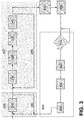
- FIG 3 shows an exemplary flowchart for performing the preferred method.
- the method may be performed by a system, such as the one described in previous examples.
- the system may first initiate an ID search phase (200).
- this phase at least one controller will search for and identify nodes (210) connected within the same electrical system.
- the controller will loop (250) the ID search phase (200) until all nodes are identified and unique IDs are acquired from and/or assigned to every node.
- the list of nodes may be compared by a provided list, which could allow for flagging defective nodes.
- the controller After finishing the ID Search phase the controller will thus acquire a list of nodes present in the network and their corresponding unique IDs. For example, the system may discover 'x'-amount of nodes.
- the system may continue with a position discovery phase (300).
- the controller may perform the method for determining an electrical position according to one or more embodiments described herein.
- the controller may commence by addressing a first node with a first "Unique Addressing Signal", which may be followed by a "Sinking or sourcing of the positioning current" command (310) instructing the first node to start sinking or sourcing the positioning current and become a sinking/sourcing node.
- the system may continue by addressing a group of nodes with a second "Global Addressing Signal", which may be followed by a "Registration of the positioning current” command (320).
- the system may once again address the sinking/sourcing node with the "Unique Addressing Signal”, which may be followed by a "Stop sinking or sourcing of the positioning current” command (330) instructing the first node to stop sinking or sourcing the positioning current.
- the system may once again address the group of nodes, which may be a part or all of the nodes, with a second "Global Addressing Signal", which may be followed by a "Reporting of a positioning current” command (340).
- the controller may loop (350) the position discovery phase (300) until the electrical position of every node is identified.
- the system may compile a table of electrical positions (400).
- the listed positions may be relative, for instance a list comprising the position of every node relative to every other node in relative terms such as downstream or upstream, and/or the listed positions may be absolute, for instance a list of physical positions of every node in the system in absolute terms such as distances.
- the compiling may simplify to ordering the list of nodes and their unique IDs according to the number of positioning currents they observed and did not observe.
- a node that observed all positioning currents may be assigned the first electrical position downstream, i.e. the beginning of the string closest to the controller; whereas another node that observed no or only its own positioning may be assigned the last electrical downstream position, i.e. the end of the string farthest away from to the controller.
- the amount of electrical positions determined during the position discovery phase (300) will preferably correspond to 'x', which is the amount of nodes identified during the position ID search phase (200).
- the system may go idle or enter a stand-by mode (450).
- the system may be configured for performing additional steps for updating and/or verifying (500) the electrical position of nodes present in or absent from the table of electrical positions.
- the system may leave the stand-by mode (450) responsive to a trigger (510).
- the trigger may for instance be a maintenance trigger (e.g. started by a user such as a technician), but it may also be an automated trigger (e.g.
- the system may start establishing communication with every nodes previously identified to verify whether they are still present and/or in the same positions as determined previously (520). Any observed discrepancies (530) may be stored in an updated table of electrical positions. The system may be instructed to overwrite the previous table, or alternatively flag and signal all the discrepancies. In the particular case of a missing node (e.g. absent, defective, removed, etc.), the system may identify the absence of said node, subsequently update the table of electrical positions and optionally flag the missing node as a defective node and report the defective node.
- a missing node e.g. absent, defective, removed, etc.
- the system may identify that the unique ID and/or electrical position corresponds with that of a previously identified node, subsequently update the table of electrical positions and optionally flag the node as a replaced or rearranged node.
- the system may loop back (540) to the ID search phase (200), acquiring and/or assigning a unique ID for the new node and determining its electrical position.
Landscapes
- Engineering & Computer Science (AREA)
- Computer Networks & Wireless Communication (AREA)
- Signal Processing (AREA)
- Cable Transmission Systems, Equalization Of Radio And Reduction Of Echo (AREA)
- Small-Scale Networks (AREA)
Priority Applications (2)
| Application Number | Priority Date | Filing Date | Title |
|---|---|---|---|
| EP17210237.8A EP3503477A1 (fr) | 2017-12-22 | 2017-12-22 | Système et procédé permettant de déterminer la position de n uds dans un système de bus à deux fils |
| PCT/EP2018/086556 WO2019122322A1 (fr) | 2017-12-22 | 2018-12-21 | Système et procédé permettant de déterminer la position de nœuds dans un système de bus bifilaire |
Applications Claiming Priority (1)
| Application Number | Priority Date | Filing Date | Title |
|---|---|---|---|
| EP17210237.8A EP3503477A1 (fr) | 2017-12-22 | 2017-12-22 | Système et procédé permettant de déterminer la position de n uds dans un système de bus à deux fils |
Publications (1)
| Publication Number | Publication Date |
|---|---|
| EP3503477A1 true EP3503477A1 (fr) | 2019-06-26 |
Family
ID=60937569
Family Applications (1)
| Application Number | Title | Priority Date | Filing Date |
|---|---|---|---|
| EP17210237.8A Withdrawn EP3503477A1 (fr) | 2017-12-22 | 2017-12-22 | Système et procédé permettant de déterminer la position de n uds dans un système de bus à deux fils |
Country Status (2)
| Country | Link |
|---|---|
| EP (1) | EP3503477A1 (fr) |
| WO (1) | WO2019122322A1 (fr) |
Families Citing this family (2)
| Publication number | Priority date | Publication date | Assignee | Title |
|---|---|---|---|---|
| CN114710530A (zh) * | 2022-03-31 | 2022-07-05 | 天津华宁电子有限公司 | 一种矿用双线网络控制系统 |
| EP4312408A1 (fr) * | 2022-07-25 | 2024-01-31 | Melexis Technologies NV | Procédé d'autoconfiguration d'un réseau de communication |
Citations (1)
| Publication number | Priority date | Publication date | Assignee | Title |
|---|---|---|---|---|
| EP3209001A1 (fr) * | 2016-02-19 | 2017-08-23 | NXP USA, Inc. | N uds de communication à auto-adressage |
Family Cites Families (2)
| Publication number | Priority date | Publication date | Assignee | Title |
|---|---|---|---|---|
| EP2154831A1 (fr) * | 2008-08-11 | 2010-02-17 | Siemens Aktiengesellschaft | Procédé de détermination de l'adresse ou de la position d'un abonné |
| US8525477B2 (en) * | 2010-07-15 | 2013-09-03 | O2Micro, Inc. | Assigning addresses to multiple cascade battery modules in electric or electric hybrid vehicles |
-
2017
- 2017-12-22 EP EP17210237.8A patent/EP3503477A1/fr not_active Withdrawn
-
2018
- 2018-12-21 WO PCT/EP2018/086556 patent/WO2019122322A1/fr not_active Ceased
Patent Citations (1)
| Publication number | Priority date | Publication date | Assignee | Title |
|---|---|---|---|---|
| EP3209001A1 (fr) * | 2016-02-19 | 2017-08-23 | NXP USA, Inc. | N uds de communication à auto-adressage |
Also Published As
| Publication number | Publication date |
|---|---|
| WO2019122322A1 (fr) | 2019-06-27 |
Similar Documents
| Publication | Publication Date | Title |
|---|---|---|
| TWI446683B (zh) | 分散式電池管理系統及其標識分配方法 | |
| EP2760165B1 (fr) | Systèmes, méthodes pour la détection de la topologie et des fautes pour un bus dans un réseau. | |
| US20060109203A1 (en) | Method for the allocation of short addresses in illumination systems | |
| US9037918B2 (en) | Systems and methods to detect bus network fault and topology | |
| KR20110031489A (ko) | Led 조명 장치의 상대 위치를 결정하는 방법 및 장치 | |
| CN107210932B (zh) | 用于在网络系统中启用故障恢复的网络节点与方法以及计算机可读介质 | |
| US10477372B2 (en) | Inter-operable remote terminal unit | |
| CN101447894A (zh) | 识别分节点物理地址、网络配置及维护方法、网络系统 | |
| US10601650B2 (en) | Method for automated configuration of an IED | |
| EP3503477A1 (fr) | Système et procédé permettant de déterminer la position de n uds dans un système de bus à deux fils | |
| US20170171355A1 (en) | Method for transferring a new software version to at least one electricity meter via a communication network | |
| CN111290351A (zh) | 一种驱动器管理方法、系统、计算机设备及存储介质 | |
| CN101681154A (zh) | 利用Profinet进行工具识别 | |
| CN112671584B (zh) | 网络拓扑的识别方法、装置、系统和存储介质 | |
| CN105282904A (zh) | 一种基于dmx512协议的控制系统及其控制方法 | |
| CN118713994B (zh) | 用于epa系统的全自动组态配置方法、主机、计算机可读存储介质和计算机程序产品 | |
| CN114859867A (zh) | 一种ecu自动编号方法、装置、终端设备及存储介质 | |
| CN111133839A (zh) | 调试有线通信网络的方法 | |
| CN117459378A (zh) | 用于通信网络的自动配置的协议 | |
| CN117678202A (zh) | 用于协调10base-t1s以太网网络中的多个节点的方法、系统和设备 | |
| CN118041892B (zh) | 用于储能系统的地址分配方法、储能系统及可读存储介质 | |
| US20240031239A1 (en) | Method of autoconfiguration of communication network | |
| CN115292112A (zh) | 从机设备的检测方法、装置、存储介质及电子装置 | |
| CN107453903A (zh) | 一种识别通讯从站的方法和系统以及一种存储设备 | |
| JP5883164B2 (ja) | ネットワークを駆動する方法 |
Legal Events
| Date | Code | Title | Description |
|---|---|---|---|
| PUAI | Public reference made under article 153(3) epc to a published international application that has entered the european phase |
Free format text: ORIGINAL CODE: 0009012 |
|
| AK | Designated contracting states |
Kind code of ref document: A1 Designated state(s): AL AT BE BG CH CY CZ DE DK EE ES FI FR GB GR HR HU IE IS IT LI LT LU LV MC MK MT NL NO PL PT RO RS SE SI SK SM TR |
|
| AX | Request for extension of the european patent |
Extension state: BA ME |
|
| STAA | Information on the status of an ep patent application or granted ep patent |
Free format text: STATUS: THE APPLICATION IS DEEMED TO BE WITHDRAWN |
|
| 18D | Application deemed to be withdrawn |
Effective date: 20200103 |