EP3503668B1 - Procédé d'établissement de liaison et terminal - Google Patents
Procédé d'établissement de liaison et terminal Download PDFInfo
- Publication number
- EP3503668B1 EP3503668B1 EP17850303.3A EP17850303A EP3503668B1 EP 3503668 B1 EP3503668 B1 EP 3503668B1 EP 17850303 A EP17850303 A EP 17850303A EP 3503668 B1 EP3503668 B1 EP 3503668B1
- Authority
- EP
- European Patent Office
- Prior art keywords
- link
- network device
- rrc link
- rrc
- terminal device
- Prior art date
- Legal status (The legal status is an assumption and is not a legal conclusion. Google has not performed a legal analysis and makes no representation as to the accuracy of the status listed.)
- Active
Links
Images


Classifications
-
- H—ELECTRICITY
- H04—ELECTRIC COMMUNICATION TECHNIQUE
- H04W—WIRELESS COMMUNICATION NETWORKS
- H04W76/00—Connection management
- H04W76/20—Manipulation of established connections
- H04W76/27—Transitions between radio resource control [RRC] states
-
- H—ELECTRICITY
- H04—ELECTRIC COMMUNICATION TECHNIQUE
- H04W—WIRELESS COMMUNICATION NETWORKS
- H04W76/00—Connection management
- H04W76/10—Connection setup
- H04W76/15—Setup of multiple wireless link connections
-
- H—ELECTRICITY
- H04—ELECTRIC COMMUNICATION TECHNIQUE
- H04W—WIRELESS COMMUNICATION NETWORKS
- H04W36/00—Hand-off or reselection arrangements
- H04W36/24—Reselection being triggered by specific parameters
- H04W36/30—Reselection being triggered by specific parameters by measured or perceived connection quality data
- H04W36/305—Handover due to radio link failure
-
- H—ELECTRICITY
- H04—ELECTRIC COMMUNICATION TECHNIQUE
- H04W—WIRELESS COMMUNICATION NETWORKS
- H04W56/00—Synchronisation arrangements
- H04W56/004—Synchronisation arrangements compensating for timing error of reception due to propagation delay
- H04W56/0045—Synchronisation arrangements compensating for timing error of reception due to propagation delay compensating for timing error by altering transmission time
-
- H—ELECTRICITY
- H04—ELECTRIC COMMUNICATION TECHNIQUE
- H04W—WIRELESS COMMUNICATION NETWORKS
- H04W76/00—Connection management
- H04W76/10—Connection setup
- H04W76/11—Allocation or use of connection identifiers
-
- H—ELECTRICITY
- H04—ELECTRIC COMMUNICATION TECHNIQUE
- H04W—WIRELESS COMMUNICATION NETWORKS
- H04W72/00—Local resource management
- H04W72/20—Control channels or signalling for resource management
- H04W72/23—Control channels or signalling for resource management in the downlink direction of a wireless link, i.e. towards a terminal
-
- H—ELECTRICITY
- H04—ELECTRIC COMMUNICATION TECHNIQUE
- H04W—WIRELESS COMMUNICATION NETWORKS
- H04W76/00—Connection management
- H04W76/10—Connection setup
- H04W76/19—Connection re-establishment
Definitions
- This application relates to the wireless communications field, and in particular, to a link setup method and a terminal device.
- Availability of a radio access network (radio access network, RAN) is an important indicator for measuring performance of the radio access network, and the availability is a ratio of communication duration that satisfies a pre-defined latency condition and a reliability condition to total communication duration.
- a Radio Resource Control (Radio Resource Control, RRC) link between a network device and a terminal device needs to be maintained connected for a long period.
- RRC Radio Resource Control
- RLF radio link failure
- the original RRC link between the terminal device and the network device is disconnected, so random access needs to be performed again.
- the original RRC link is disconnected.
- no available RRC link exists between the terminal device and the network device, affecting data transmission.
- the random access procedure needs to consume a relatively long period, and in the random access procedure, no RRC link is available for data transmission. Consequently, reliable data transmission cannot be performed between the terminal device and the network device in the random access procedure, and communication between the terminal device and the network device cannot satisfy the pre-defined latency condition and the reliability condition, causing adverse impact to the availability of the RAN.
- the US 2014 / 0337935 A1 refers to a fast-accessing method and apparatus.
- This application provides a link setup method and a terminal device.
- a terminal device maintains RRC links to at least two network devices for a long period.
- RLF radio link failure
- a link modification request may be initiated through a link providing a normal service, so that the RRC link in which the RLF or the signal deterioration occurs is replaced in time. Therefore, the RRC link is not disconnected for a long period, helping satisfying the severe performance indicators of a 5G service.
- time consumed by an RRC link setup process is shortened, to reduce adverse impact, on availability of a RAN, caused by the procedure of setting up the RRC link by the terminal device.
- this application provides a link setup method as defined by independent claim 1.
- this application further provides a terminal device as defined by independent claim 6.
- the terminal device can set up the target RRC link through the first RRC link that can normally work, thereby greatly shortening the latency consumed by the RRC link setup process, and reducing the adverse impact, on the availability of the RAN, caused by the process of setting up the RRC link by the terminal device.
- This application can be applied to a wireless communications system including a network device and a terminal device, for example, an LTE system; or other wireless communications system using various wireless access technologies, for example, a system using an access technology such as Code Division Multiple Access, Frequency Division Multiple Access, Time Division Multiple Access, orthogonal frequency division multiple access, or single carrier frequency division multiple access, and a subsequent evolved system such as a fifth-generation 5G system.
- a wireless communications system including a network device and a terminal device, for example, an LTE system; or other wireless communications system using various wireless access technologies, for example, a system using an access technology such as Code Division Multiple Access, Frequency Division Multiple Access, Time Division Multiple Access, orthogonal frequency division multiple access, or single carrier frequency division multiple access, and a subsequent evolved system such as a fifth-generation 5G system.
- the terminal device may be a device that provides voice and/or data connectivity to a user, a handheld device having a wireless connection function, or another processing device connected to a radio modem.
- the terminal device may communicate with one or more core networks using a radio access network (radio access network, RAN).
- the terminal device may be a mobile terminal, such as a mobile phone (or referred to as a "cellular" phone) or a computer having a mobile terminal, for example, may be a portable, pocket-sized, handheld, computer built-in, or in-vehicle mobile apparatus.
- the terminal device exchanges voice and/or data with the radio access network.
- the terminal device may be a device such as a personal communication service (personal communication service, PCS) phone, a cordless telephone set, a Session Initiation Protocol (Session Initiation Protocol, SIP) phone, a wireless local loop (wireless local loop, WLL) station, or a personal digital assistant (personal digital assistant, PDA).
- PCS personal communication service
- SIP Session Initiation Protocol
- WLL wireless local loop
- PDA personal digital assistant
- the terminal device may also be referred to as a system, a subscriber unit (subscriber unit, SU), a subscriber station (subscriber station, SS), a mobile station (mobile station, MS), a remote station (remote station, RS), an access point (access point, AP), a remote terminal (remote terminal, RT), an access terminal (access terminal, AT), a user terminal (user terminal, UT), a user agent (user agent, UA), a user device, or user equipment (user equipment, UE).
- the network device may be a base station, an enhanced base station, a relay having a scheduling function, a device having a base station function, or the like.
- the base station may be an evolved NodeB (evolved NodeB, eNB) in an LTE system, or a base station in another system. This is not limited in this embodiment of this application.
- eNB evolved NodeB
- Each network device may provide a service to at least one cell, or different network devices may provide services to a same cell.
- FIG. 1 is a schematic structural diagram of a radio access network according to this application.
- the radio access network may include at least two network devices.
- Each network device may correspond to a cell, and provide a service to only the cell corresponding to the network device.
- a terminal device may maintain RRC links to at least two network devices in the RAN, to improve availability of the RAN, and satisfy the transmission requirements of a low latency and high reliable service.
- the terminal device maintains the RRC links to the at least two network devices, if a radio link failure occurs in one of the RRC links, at least one available RRC link still exists between the terminal device and the RAN, thereby avoiding a case in which the terminal device cannot communicate with the network device because a control plane connection is disconnected.
- the terminal device has a first RRC link to a first network device, and further has a second RRC link to a second network device.
- the terminal device maintains the RRC links to the first network device and the second network device, so that when one of the RRC links is faulty, the other RRC link can still normally transmit RRC signaling, so that it is ensured that the RRC link between the terminal device and the RAN is not broken for a long period, thereby greatly improving the availability of the RAN.
- the terminal device may still resume the disconnected RRC link or set up a new RRC link through the RRC link that is normally used, to avoid time consumption caused by reestablishing or resuming the RRC link in a random access manner, and reduce, as much as possible, a case in which the terminal device has an RRC link to only one network device, thereby ensuring relatively high availability of the RAN.
- the first RRC link may be any RRC link through which the terminal device and the network device can normally communicate with each other
- the second RRC link is an RRC link other than the first RRC link between the terminal device and the network device.
- the first network device and the second network device usually are different network devices, and a target network device and the second network device may be a same network device.
- the first network device and the second network device may alternatively be a same network device.
- the first network device and the second network device belong to a same RAN.
- FIG. 2 is a flowchart of an embodiment of a link setup method according to this application. The method in this embodiment may be applied after a terminal device sets up a first RRC link to a first network device.
- Step 201 The terminal device determines a device identifier of a target network device.
- the terminal device may select a network device that the terminal device can access from network devices included in a RAN as the target network device, and determine the device identifier of the target network device.
- the target network device may be a second network device, or may be another network device.
- the preset condition may be that after the first RRC link is set up, the terminal device further needs to set up another RRC link to another network device, to implement that RRC links exists between the terminal device and at least two network devices.
- the preset condition may be that after both the first RRC link and a second RRC link are set up, a target RRC link is set up to replace the second RRC link, to ensure that RRC links exists between the terminal device and at least two network devices.
- the terminal device may further determine the target network device and the device identifier of the target network device according to indication information sent by the network device.
- the second network device may alternatively send indication information to the terminal device through the second RRC link or through the first network device through the first RRC link.
- the indication information may carry the device identifier of the target network device.
- Step 202 The terminal device sends a first link modification request to the first network device through the first RRC link, where the first link modification request carries the device identifier of the target network device.
- the first RRC link is set up and can normally work, so that after the device identifier is determined, the terminal device sends the first link modification request to the first network device through the first RRC link.
- the first link modification request is used to request to set up the target RRC link.
- There may be various types of signaling for carrying the first link modification request for example, the first link modification request may be carried in an RRC link resume request message (RRC connection resume request), an RRC link setup request message (RRC connection setup request), an RRC link reestablishment request message (RRC connection reestablishment request), or another uplink RRC message; or the first link modification request may alternatively be the request message.
- the terminal device sends the first link modification request to the first network device through the first RRC link, to set up the target RRC link, thereby implementing that RRC links exist between the terminal device and at least two network devices.
- the target network device is the second network device.
- the terminal device sends the first link modification request to the first network device through the first RRC link, to set up the target RRC link to replace the second RRC link.
- the target network device may be the second network device, or may be a network device other than the second network device.
- That an RLF occurs in the second RRC link may include: an integrity check failure indication for the second RRC link is received from a physical layer, a reconfiguration failure occurs in the second RRC link, or the like.
- That channel quality deterioration occurs in the second RRC link may be that channel quality of the second RRC link is less than a pre-defined value or the like.
- Step 203 The first network device sends a second link modification request to the target network device.
- the first network device may determine the target network device based on the device identifier carried in the first link request, and then sends the second link modification request to the target network device.
- the second link modification request may be used to request the target network device to set up an RRC link to the terminal device. Signaling used to carry the second link modification request may be the same as signaling used to carry the first link modification request.
- the first network device may further obtain a context of the terminal device on the second RRC link, and generate a second link modification request carrying the context or use the context as the second link modification request.
- the context may include an uplink signal configuration used for timing used by the terminal device.
- Step 204 The target network device sends a first modification indication to the first network device.
- the first modification indication may include a container (container) message of an RRC link modification message and a transmission parameter.
- the target network device may determine the transmission parameter used by the terminal device to access the target network device, and send the transmission parameter and the RRC link modification message to the first network device.
- the RRC link modification message may be carried in a form of the container message.
- the transmission parameter may include a C-RNTI of the target network device.
- the transmission parameter may alternatively include other information.
- the target network device when the second link modification request carries the uplink signal configuration required for calculating the timing used by the terminal device, the target network device generates an uplink scheduling grant UL Grant, generates a timing advance TA adjustment command based on the uplink signal configuration, and adds the uplink scheduling grant and the timing advance TA adjustment command to the transmission parameter.
- Step 205 The first network device sends a second modification indication to the terminal device through the first RRC link.
- the second modification indication includes the RRC link modification message and the transmission parameter.
- the first network device may forward the RRC link modification message and the transmission parameter to the terminal device through the first RRC link.
- Step 206 The terminal device sets up a target RRC link to the target network device based on a transmission parameter.
- the terminal device After the terminal device receives the RRC link modification message, it indicates that the target network device already allows the terminal device to set up the RRC link to the target network device. Therefore, the terminal device sets up the target RRC link based on the transmission parameter, and send an RRC link modification complete message to the target network device, to complete the setup of the target RRC link.
- manners of sending the RRC link modification complete message to the target network device by the terminal device may also be different.
- the terminal device may send the RRC link modification complete message to the first network device through the first RRC link, and the first network device forwards the RRC link modification complete message to the target network device.
- the terminal device may further monitor downlink scheduling information of the target network device using the C-RNTI, to complete data transmission based on the downlink scheduling information.
- the terminal device when the transmission parameter is uplink scheduling information, the terminal device sends the RRC link modification complete message to the target network device based on scheduling using the uplink scheduling information, to indicate that the target RRC link is set up.
- the target RRC link is set up using the method provided in this embodiment. Because a random access process is avoided, time consumed by the target RRC link setup process can be greatly shortened. Therefore, a case in which the terminal device has an RRC link to only one network device is reduced, thereby ensuring relatively high availability of the RAN.
- FIG. 3 is a schematic structural diagram of an embodiment of a terminal device according to this application.
- the terminal device may be the terminal device in any of the foregoing embodiments.
- the terminal device may include a receiving unit 301, a processing unit 302, and a sending unit 303.
- the sending unit 303 is configured to send a first link modification request to a first network device through a first RRC link, and the first link modification request carries a device identifier of a target network device, to request to set up a target RRC link to the target network device.
- the receiving unit 301 is configured to receive a second modification indication sent by the first network device through the first RRC link, and the second modification indication includes an RRC link modification message and a transmission parameter, and the RRC link modification message and the transmission parameter are both generated by the target network device.
- the processing unit 302 is configured to: after the receiving unit 301 receives the RRC link modification message, set up the target RRC link to the target network device based on the transmission parameter, and maintain the target RRC link and the first RRC link.
- the processing unit 302 is further configured to: select the target network device, and determine the device identifier of the target network device.
- the sending unit 303 is specifically configured to: when an established second RRC link is faulty, send the first link modification request to the first network device through the first RRC link, and the first link modification request carries the device identifier of the target network device.
- the sending unit 303 is specifically configured to: after the first RRC link is set up, if a quantity of RRC links maintained between the terminal device and all network devices does not reach a threshold, send the first link modification request to the first network device through the first RRC link.
- the processing unit 302 is specifically configured to: reestablish or resume the second RRC link based on the transmission parameter, and maintain the second RRC link and the first RRC link.
- the sending unit 303 is further configured to: when the transmission parameter is uplink scheduling information used to schedule an RRC link modification complete message, send the RRC link modification complete message to the target network device in uplink based on scheduling using the uplink scheduling information, and the uplink scheduling information includes a timing advance TA adjustment command and an uplink scheduling grant UL Grant of the target network device.
- the sending unit 303 is further configured to: when the transmission parameter is a cell radio network temporary identifier C-RNTI used for scheduling performed by the target network device, send the RRC link modification complete message to the first network device through the first RRC link; and the receiving unit is further configured to monitor downlink scheduling information of the target network device using the C-RNTI.
- the transmission parameter is a cell radio network temporary identifier C-RNTI used for scheduling performed by the target network device
- the receiving unit is further configured to monitor downlink scheduling information of the target network device using the C-RNTI.
- FIG. 4 is a schematic structural diagram of an embodiment of a network device according to this application (this embodiment is however not covered by the claims).
- the network device may be the first network device, the second network device, or the target network device in the foregoing embodiments.
- the network device may include a receiving unit 401, a processing unit 402, and a sending unit 403.
- the receiving unit 401 is configured to receive a first link modification request sent by a terminal device through a first RRC link, and the first link modification request carries a device identifier; the processing unit 402 is configured to determine a target network device corresponding to the device identifier; and the sending unit 403 is configured to send a second link modification request to the target network device.
- the receiving unit 401 is further configured to receive a first modification indication sent by the target network device, the modification indication includes a container message of an RRC link modification message and a transmission parameter, and the RRC link modification message and the transmission parameter are sent by the target network device in response to the second link modification request.
- the sending unit 403 is further configured to send a second modification indication to the terminal device through the first RRC link, and the second modification indication includes the RRC link modification message and the transmission parameter.
- the second link modification request may include a context of the terminal device on a second RRC link.
- the context may include an uplink signal configuration used for timing used by the terminal device.
- the transmission parameter may include uplink scheduling information used to schedule the terminal device to send an RRC link modification complete message to the target network device or a cell radio network temporary identifier C-RNTI used for scheduling performed by the target network device.
- the receiving unit 401 is further configured to receive the RRC link modification complete message sent by the terminal device; and the sending unit 403 is further configured to send the RRC link modification complete message to the target network device.
- the receiving unit 401 is configured to receive a second link modification request sent by a first network device, and the second link modification request is sent after the first network device receives a first link modification request sent by a terminal device through a first RRC link, and the first RRC link is an RRC link between the first network device and the terminal device;
- the processing unit 402 is configured to generate a transmission parameter in response to the second link modification request, and the transmission parameter is a parameter required for setting up a target RRC link between the terminal device and the target network device;
- the sending unit 403 is configured to send a first modification indication to the first network device, and the first modification indication includes a container message of an RRC link modification message and the transmission parameter.
- the processing unit 402 is specifically configured to: when the second link modification request carries an uplink signal configuration required for calculating timing used by the terminal device, generate an uplink scheduling grant UL Grant, and generate a timing advance TA adjustment command based on the uplink signal configuration.
- the processing unit 402 is specifically configured to obtain a cell radio network temporary identifier C-RNTI used for scheduling performed by the target network device.
- FIG. 5 is a schematic structural diagram of an embodiment of a terminal device according to this application.
- the terminal device may be the terminal device in any of the foregoing embodiments, and configured to implement the method steps that need to be implemented by the terminal device in the foregoing embodiments.
- the terminal device may include a processor 501, a memory 502, and a transceiver module 503.
- the transceiver module 503 may include components such as a receiver 5031, a transmitter 5032, and an antenna 5033.
- the terminal device may alternatively include more components or fewer components, or some components may be combined, or a different component deployment may be used. This is not limited in this application.
- the processor 501 is a control center of the terminal device, and is connected to all parts of the entire terminal device through various interfaces and lines. By running or executing a software program and/or module stored in the memory 502, and invoking data stored in the memory 502, the processor 501 performs various functions and/or data processing of the terminal device.
- the processor 501 may include an integrated circuit (integrated circuit, IC), for example, may include a single packaged IC, or may include a plurality of linked packaged ICs that have a same function or different functions.
- the processor may include only a central processing unit (central processing unit, CPU), or may be a combination of a GPU, a digital signal processor (digital signal processor, DSP), and a control chip (such as a baseband chip) in the transceiver module 503.
- CPU central processing unit
- DSP digital signal processor
- the CPU may include a single operation core, or may include a plurality of operation cores.
- the transceiver module 503 is configured to set up a communications channel, so that the terminal device is linked to a receive device through the communication channel, thereby implementing data transmission to the terminal device.
- the transceiver module 503 may include a communications module such as a wireless local area network (wireless local area network, WLAN) module, a Bluetooth module, or a baseband (baseband) module, and a radio frequency (radio frequency, RF) circuit corresponding to the communications module, and is configured to perform wireless local area network communication, Bluetooth communication, infrared communication, and/or cellular communications system communication, for example, Wideband Code Division Multiple Access (wideband code division multiple access, WCDMA) and/or High Speed Downlink Packet Access (high speed downlink packet access, HSDPA).
- the transceiver module 503 is configured to control communication between components in the terminal device, and may support direct memory access (direct memory access).
- various communications modules in the transceiver module 503 are usually presented in a form of an integrated circuit chip (integrated circuit chip), and may be selectively combined, and the transceiver module 503 does not need to include all the communications modules and corresponding antenna groups.
- the transceiver module 503 may include only a baseband chip, a radio frequency chip, and a corresponding antenna, to provide a communication function in a cellular communications system.
- the terminal device may be linked to a cellular network (cellular network) or the Internet (Internet) through a wireless communications link, such as wireless local area network access or WCDMA access, set up by the transceiver module 503.
- the communications module such as the baseband module, in the transceiver module 503, may be integrated into the processor.
- An APQ+MDM series platform provided by Qualcomm (Qualcomm) is a typical example.
- the radio frequency circuit is configured to receive and send a signal during an information receiving and sending process or during a call. For example, the radio frequency circuit receives downlink information from a network device, then sends the downlink information to the processor for processing, and sends uplink-related uplink data to the network device.
- the radio frequency circuit includes a known circuit for performing these functions, which includes but is not limited to an antenna system, a radio frequency transceiver, one or more amplifiers, a tuner, one or more oscillators, a digital signal processor, a codec (Codec) chip set, a subscriber identity module (SIM), a memory, and the like.
- the radio frequency circuit may also communicate with a network and another device by means of wireless communication.
- the wireless communication may use any communications standard or protocol, including, but is not limited to, Global System for Mobile communications (global system of mobile communication, GSM), general packet radio service (general packet radio service, GPRS), Code Division Multiple Access (code division multiple access, CDMA), Wideband Code Division Multiple Access (wideband code division multiple access, WCDMA for short), High Speed Uplink Packet Access (high speed uplink packet access, HSUPA), Long Term Evolution (long term evolution, LTE), email, short message service (short messaging service, SMS), and the like.
- GSM Global System for Mobile communications
- GSM global system of mobile communication
- GPRS general packet radio service
- Code Division Multiple Access code division multiple access
- CDMA Code Division Multiple Access
- Wideband Code Division Multiple Access Wideband code division multiple access
- WCDMA for short
- High Speed Uplink Packet Access high speed uplink packet access
- HSUPA Long Term Evolution
- email short message service
- short messaging service short messaging service
- the method steps performed by the terminal device in the foregoing embodiments may be performed by the processor 501 or the transceiver 503 in this embodiment.
- the function that needs to be implemented by the receiving unit 301 may be implemented by the transceiver module 503 of the terminal device, or implemented by the transceiver module 503 controlled by the processor 501;
- the function that needs to be implemented by the sending unit 303 may also be implemented by the transceiver module 503 of the terminal device, or may also be implemented by the transceiver module 503 controlled by the processor 501;
- the function that needs to be implemented by the processing unit 302 may be implemented by the processor 501.
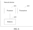
- FIG. 6 is a schematic structural diagram of another embodiment of a network device according to this application (this embodiment is however not covered by the claims).
- the network device may include a processor 601, a memory 602, a transceiver 603, and the like.
- the processor 601 is a control center of the network device, and is connected to all parts of the entire network device through various interfaces and lines. By running or executing a software program and/or module stored in the memory, and invoking data stored in the memory, the processor 601 performs various functions and/or data processing of the network device.
- the processor may be a central processing unit (central processing unit, CPU), a network processor (network processor, NP), or a combination of a CPU and an NP.
- the processor may further include a hardware chip.
- the hardware chip may be an application-specific integrated circuit (application-specific integrated circuit, ASIC), a programmable logic device (programmable logic device, PLD), or a combination thereof.
- the PLD may be a complex programmable logic device (complex programmable logic device, CPLD), a field-programmable gate array (field-programmable gate array, FPGA), a generic array logic (generic array logic, GAL for short), or any combination thereof.
- complex programmable logic device complex programmable logic device, CPLD
- field-programmable gate array field-programmable gate array
- FPGA field-programmable gate array
- GAL generic array logic
- the memory 602 may include a volatile memory (volatile memory), for example, a random access memory (random access memory, RAM).
- the memory 30 may alternatively include a non-volatile memory (non-volatile memory), for example, a flash memory (flash memory), a hard disk drive (hard disk drive, HDD), or a solid-state drive (solid-state drive, SSD).
- the memory may alternatively include a combination of the foregoing types of memories.
- the memory may store a program or code.
- a processor in a network element may implement a function of the network element by performing the program or the code.
- the transceiver 603 may be configured to receive or send data.
- the transceiver may send data to a terminal device or another network device under control of the processor.
- the transceiver receives, under control of the processor, data sent by the terminal device or another network device.
- the method steps performed by the first network device or the target network device in the foregoing embodiments may be performed by the processor 601 or the transceiver 603 in this embodiment.
- the function that needs to be implemented by the receiving unit 401 may be implemented by the transceiver 603 of the terminal device, or implemented by the transceiver 603 controlled by the processor 601;
- the function that needs to be implemented by the sending unit 403 may also be implemented by the transceiver 603 of the terminal device, or may also be implemented by the transceiver 603 controlled by the processor 601;
- the function that needs to be implemented by the processing unit 402 may be implemented by the processor 601.
- This application further provides a wireless communications system, including a first network device, a target network device, and a terminal device (this system is however not covered by the claims).
- the terminal device is configured to send a first link modification request to the first network device through a first RRC link, and the first link modification request carries a device identifier used to identify the target network device.
- the first network device is configured to: after receiving the first link modification request, determine the target network device corresponding to the device identifier, and send a second link modification request to the target network device.
- the target network device is configured to: receive the second link modification request sent by the first network device; generate a transmission parameter in response to the second link modification request, where the transmission parameter is a parameter required for setting up a target RRC link between the terminal device and the target network device; and send a first modification indication to the first network device, where the first modification indication includes a container message of an RRC link modification message and the transmission parameter.
- the first network device is further configured to: receive the RRC link modification message and the transmission parameter; and send a second modification indication to the terminal device through the first RRC link, where the second modification indication includes the RRC link modification message and the transmission parameter.
- the terminal device is further configured to: set up the target RRC link to the target network device based on the transmission parameter, and maintain the target RRC link and the first RRC link.
- the wireless communications system may alternatively include only the first network device and the target network device.
- the wireless communications system may further include a second network device.
- this application further provides a computer storage medium.
- the computer storage medium may store a program, and when the program is executed, some or all of the steps of the embodiments of the calling method provided in this application may be performed.
- the storage medium may be a magnetic disk, an optical disc, a read-only memory (English: read-only memory, ROM), a random access memory (English: random access memory, RAM), or the like.
- the software product may be stored in a storage medium, such as a ROM/RAM, a magnetic disk, or an optical disc, and includes several instructions for instructing a computer device (which may be a personal computer, a server, or a network device) to perform the methods described in the embodiments or some parts of the embodiments of this application.
- a computer device which may be a personal computer, a server, or a network device
Landscapes
- Engineering & Computer Science (AREA)
- Computer Networks & Wireless Communication (AREA)
- Signal Processing (AREA)
- Mobile Radio Communication Systems (AREA)
Claims (7)
- Procédé d'établissement de liaison, comportant :l'envoi (202), par un dispositif terminal, d'une première demande de modification de liaison à un premier dispositif de réseau par l'intermédiaire d'une première liaison de gestion des ressources radioélectriques, RRC, la première demande de modification de liaison transportant un identifiant de dispositif d'un dispositif de réseau cible, pour demander l'établissement d'une liaison RRC cible vers le dispositif de réseau cible ;la réception, par le dispositif terminal, d'une seconde indication de modification émise par le premier dispositif de réseau par l'intermédiaire de la première liaison RRC, la seconde indication de modification comportant un message de modification de liaison RRC et un paramètre de transmission, et le message de modification de liaison RRC et le paramètre de transmission étant tous deux générés par le dispositif de réseau cible ; etl'établissement (206), par le dispositif terminal, de la liaison RRC cible vers le dispositif de réseau cible sur la base du paramètre de transmission, et l'entretien à la fois de la liaison RRC cible et de la première liaison RRC, le premier dispositif de réseau étant différent du dispositif de réseau cible,le procédé étant caractérisé en ce que l'envoi (202), par le dispositif terminal, de la première demande de modification de liaison au premier dispositif de réseau par l'intermédiaire d'une première liaison RRC comporte :
après que la première liaison RRC a été établie, si une quantité de liaisons RRC entretenues entre le dispositif terminal et tous les dispositifs de réseau n'atteint pas un seuil, l'envoi, par le dispositif terminal, de la première demande de modification de liaison au premier dispositif de réseau par l'intermédiaire de la première liaison RRC. - Procédé selon la revendication 1, l'envoi (202), par un dispositif terminal, d'une première demande de modification de liaison à un premier dispositif de réseau par l'intermédiaire d'une première liaison RRC comportant :
la sélection, par le dispositif terminal, du dispositif de réseau cible, et la détermination de l'identifiant de dispositif du dispositif de réseau cible. - Procédé selon la revendication 1 ou 2, l'envoi (202), par un dispositif terminal, d'une première demande de modification de liaison à un premier dispositif de réseau par l'intermédiaire d'une première liaison RRC comportant :
lorsqu'une panne de liaison radio, RLF, ou une détérioration de la qualité de canal survient dans une seconde liaison RRC établie, l'envoi (202), par le dispositif terminal, de la première demande de modification de liaison au premier dispositif de réseau par l'intermédiaire de la première liaison RRC, la première liaison RRC étant différente de la seconde liaison RRC. - Procédé selon la revendication 3, l'établissement (206), par le dispositif terminal, de la liaison RRC cible vers le dispositif de réseau cible sur la base du paramètre de transmission, et l'entretien à la fois de la liaison RRC cible et de la première liaison RRC comportant :
le rétablissement ou la reprise, par le dispositif terminal, de la seconde liaison RRC sur la base du paramètre de transmission, et l'entretien à la fois de la seconde liaison RRC et de la première liaison RRC. - Procédé selon l'une quelconque des revendications 1 à 3, l'établissement (206), par le dispositif terminal, de la liaison RRC cible vers le dispositif de réseau cible sur la base des paramètres de transmission comportant :
lorsque le paramètre de transmission est une information de programmation de liaison montante utilisée pour programmer un message d'achèvement de modification de liaison RRC, l'envoi, par le dispositif terminal, du message d'achèvement de modification de liaison RRC au dispositif de réseau cible d'après une programmation utilisant l'information de programmation de liaison montante, l'information de programmation de liaison montante comportant une consigne de réglage d'avance de synchronisation, TA, et une autorisation de programmation de liaison montante, autorisation UL, du dispositif de réseau cible. - Dispositif terminal, comportant :une unité (303) d'émission, configurée pour envoyer une première demande de modification de liaison à un premier dispositif de réseau par l'intermédiaire d'une première liaison de gestion des ressources radioélectriques, RRC, la première demande de modification de liaison transportant un identifiant de dispositif d'un dispositif de réseau cible, pour demander l'établissement d'une liaison RRC cible vers le dispositif de réseau cible ;une unité (301) de réception, configurée pour recevoir une seconde indication de modification émise par le premier dispositif de réseau par l'intermédiaire de la première liaison RRC, la seconde indication de modification comportant un message de modification de liaison RRC et un paramètre de transmission, et le message de modification de liaison RRC et le paramètre de transmission étant tous deux générés par le dispositif de réseau cible ; etune unité (302) de traitement, configurée pour : après que l'unité (301) de réception a reçu le message de modification de liaison RRC, établir la liaison RRC cible vers le dispositif de réseau cible sur la base du paramètre de transmission, et entretenir à la fois la liaison RRC cible et la première liaison RRC,le dispositif terminal étant caractérisé en ce que l'unité (303) d'émission est spécifiquement configurée pour : après que la première liaison RRC a été établie, si une quantité de liaisons RRC entretenues entre le dispositif terminal et tous les dispositifs de réseau n'atteint pas un seuil, envoyer la première demande de modification de liaison au premier dispositif de réseau par l'intermédiaire de la première liaison RRC.
- Dispositif terminal selon la revendication 6,
l'unité (303) d'émission étant spécifiquement configurée pour : lorsqu'une seconde liaison RRC établie est défectueuse, envoyer la première demande de modification de liaison au premier dispositif de réseau par l'intermédiaire de la première liaison RRC, la première demande de modification de liaison transportant l'identifiant de dispositif du dispositif de réseau cible, et la première liaison RRC étant différente de la seconde liaison RRC.
Applications Claiming Priority (2)
| Application Number | Priority Date | Filing Date | Title |
|---|---|---|---|
| CN201610832222.9A CN108307524B (zh) | 2016-09-19 | 2016-09-19 | 链路建立方法及设备与无线通信系统 |
| PCT/CN2017/101920 WO2018050101A1 (fr) | 2016-09-19 | 2017-09-15 | Procédé et dispositif d'établissement de liaison et système de communication sans fil |
Publications (3)
| Publication Number | Publication Date |
|---|---|
| EP3503668A1 EP3503668A1 (fr) | 2019-06-26 |
| EP3503668A4 EP3503668A4 (fr) | 2019-09-25 |
| EP3503668B1 true EP3503668B1 (fr) | 2021-04-14 |
Family
ID=61618640
Family Applications (1)
| Application Number | Title | Priority Date | Filing Date |
|---|---|---|---|
| EP17850303.3A Active EP3503668B1 (fr) | 2016-09-19 | 2017-09-15 | Procédé d'établissement de liaison et terminal |
Country Status (4)
| Country | Link |
|---|---|
| US (1) | US11368999B2 (fr) |
| EP (1) | EP3503668B1 (fr) |
| CN (1) | CN108307524B (fr) |
| WO (1) | WO2018050101A1 (fr) |
Families Citing this family (10)
| Publication number | Priority date | Publication date | Assignee | Title |
|---|---|---|---|---|
| EP4224983B1 (fr) * | 2017-02-03 | 2025-10-01 | Telefonaktiebolaget LM Ericsson (publ) | Reprise de commande de ressources radio sans extraction de contexte |
| CN110798900B (zh) * | 2018-08-03 | 2024-03-05 | 华为技术有限公司 | 一种通信失败恢复的方法和装置 |
| CN110831253B (zh) * | 2018-08-08 | 2022-01-14 | 华为技术有限公司 | 连接重建方法、设备及系统 |
| CN113271623B (zh) * | 2018-08-23 | 2022-12-27 | 华为技术有限公司 | 通信方法及装置 |
| EP3897029B1 (fr) | 2018-12-29 | 2023-11-22 | Huawei Technologies Co., Ltd. | Procédé et dispositif de communication |
| CN112703698B (zh) * | 2019-01-29 | 2023-07-11 | Oppo广东移动通信有限公司 | 接入网络节点管理方法、终端设备、网络设备及存储介质 |
| CN111586851B (zh) * | 2019-02-15 | 2024-02-02 | 华为技术有限公司 | 一种通信方法及装置 |
| CN111757555B (zh) * | 2019-03-29 | 2023-01-13 | 大唐移动通信设备有限公司 | 一种连接处理方法及设备 |
| CN113455097A (zh) * | 2019-03-29 | 2021-09-28 | 华为技术有限公司 | 链路失败的恢复方法和设备 |
| CN114830725B (zh) * | 2019-12-25 | 2025-06-10 | 华为技术有限公司 | 一种通信方法及设备 |
Family Cites Families (9)
| Publication number | Priority date | Publication date | Assignee | Title |
|---|---|---|---|---|
| CN103067994A (zh) * | 2011-10-19 | 2013-04-24 | 中国电信股份有限公司 | 使无线终端在两种无线网络之间切换的方法与系统 |
| WO2013091161A1 (fr) * | 2011-12-19 | 2013-06-27 | Nokia Corporation | Procédé et appareil d'optimisation de robustesse de mobilité |
| US9807072B2 (en) * | 2012-02-06 | 2017-10-31 | Nokia Technologies Oy | Fast-accessing method and apparatus |
| KR102092063B1 (ko) * | 2013-04-26 | 2020-03-23 | 삼성전자 주식회사 | 통신 서비스 수행 방법 및 장치 |
| JP2015142363A (ja) * | 2014-01-30 | 2015-08-03 | 株式会社Nttドコモ | 移動局、再接続要求方法、基地局及び再接続要求処理方法 |
| CN104980980A (zh) * | 2014-04-10 | 2015-10-14 | 电信科学技术研究院 | 一种建立连接的方法、系统和设备 |
| EP3142452A4 (fr) * | 2014-05-07 | 2017-12-20 | Kyocera Corporation | Procédé de commande de communication, station de base et terminal d'utilisateur |
| US10772021B2 (en) * | 2014-12-05 | 2020-09-08 | Qualcomm Incorporated | Low latency and/or enhanced component carrier discovery for services and handover |
| CN108496405B (zh) * | 2015-11-30 | 2022-09-09 | 瑞典爱立信有限公司 | 用于配置集群的方法和装置 |
-
2016
- 2016-09-19 CN CN201610832222.9A patent/CN108307524B/zh active Active
-
2017
- 2017-09-15 WO PCT/CN2017/101920 patent/WO2018050101A1/fr not_active Ceased
- 2017-09-15 EP EP17850303.3A patent/EP3503668B1/fr active Active
-
2019
- 2019-03-18 US US16/356,275 patent/US11368999B2/en active Active
Non-Patent Citations (1)
| Title |
|---|
| None * |
Also Published As
| Publication number | Publication date |
|---|---|
| US20190215893A1 (en) | 2019-07-11 |
| WO2018050101A1 (fr) | 2018-03-22 |
| EP3503668A4 (fr) | 2019-09-25 |
| US11368999B2 (en) | 2022-06-21 |
| EP3503668A1 (fr) | 2019-06-26 |
| CN108307524A (zh) | 2018-07-20 |
| CN108307524B (zh) | 2021-11-19 |
Similar Documents
| Publication | Publication Date | Title |
|---|---|---|
| EP3503668B1 (fr) | Procédé d'établissement de liaison et terminal | |
| US11129068B2 (en) | Network device and terminal device applied for cell handover | |
| US9877218B2 (en) | Method and apparatus for implementing report measurement and reporting measurement result | |
| US10979942B2 (en) | Data transmission method, network device, and terminal device | |
| US11051215B2 (en) | Switching method, terminal device, and network device | |
| RU2755514C2 (ru) | Способ связи, устройство сети доступа и терминал | |
| EP3637866B1 (fr) | Procédé de radiomessagerie, dispositif de terminal et dispositif de réseau | |
| CN108029150B (zh) | 数据传输的方法和设备 | |
| US11071171B2 (en) | Path switching method and apparatus | |
| JP7816564B2 (ja) | マルチパスの設定方法、装置及びシステム | |
| WO2020119615A1 (fr) | Procédé et appareil de communication et support de stockage lisible par ordinateur | |
| US11489651B2 (en) | Frequency band state processing method and frequency band state processing device | |
| US11184807B2 (en) | Method for enabling network to fall back, terminal device, and access network device | |
| US10524172B2 (en) | User equipment and network access method | |
| CN109151939B (zh) | 调整方法、终端及网络设备 | |
| CN113424647B (zh) | 发起到目标无线通信网络的连接的方法和无线通信装置 | |
| CN112470501B (zh) | 一种寻呼消息处理方法及装置 | |
| US11082868B2 (en) | Service access method and device to determine the availability of a service path for service access |
Legal Events
| Date | Code | Title | Description |
|---|---|---|---|
| STAA | Information on the status of an ep patent application or granted ep patent |
Free format text: STATUS: THE INTERNATIONAL PUBLICATION HAS BEEN MADE |
|
| PUAI | Public reference made under article 153(3) epc to a published international application that has entered the european phase |
Free format text: ORIGINAL CODE: 0009012 |
|
| STAA | Information on the status of an ep patent application or granted ep patent |
Free format text: STATUS: REQUEST FOR EXAMINATION WAS MADE |
|
| 17P | Request for examination filed |
Effective date: 20190318 |
|
| AK | Designated contracting states |
Kind code of ref document: A1 Designated state(s): AL AT BE BG CH CY CZ DE DK EE ES FI FR GB GR HR HU IE IS IT LI LT LU LV MC MK MT NL NO PL PT RO RS SE SI SK SM TR |
|
| AX | Request for extension of the european patent |
Extension state: BA ME |
|
| A4 | Supplementary search report drawn up and despatched |
Effective date: 20190826 |
|
| RIC1 | Information provided on ipc code assigned before grant |
Ipc: H04W 76/15 20180101AFI20190820BHEP Ipc: H04W 72/12 20090101ALN20190820BHEP Ipc: H04W 76/19 20180101ALN20190820BHEP Ipc: H04W 56/00 20090101ALI20190820BHEP |
|
| DAV | Request for validation of the european patent (deleted) | ||
| DAX | Request for extension of the european patent (deleted) | ||
| STAA | Information on the status of an ep patent application or granted ep patent |
Free format text: STATUS: EXAMINATION IS IN PROGRESS |
|
| 17Q | First examination report despatched |
Effective date: 20200608 |
|
| REG | Reference to a national code |
Ref country code: DE Ref legal event code: R079 Ref document number: 602017036872 Country of ref document: DE Free format text: PREVIOUS MAIN CLASS: H04W0076100000 Ipc: H04W0076150000 |
|
| GRAP | Despatch of communication of intention to grant a patent |
Free format text: ORIGINAL CODE: EPIDOSNIGR1 |
|
| STAA | Information on the status of an ep patent application or granted ep patent |
Free format text: STATUS: GRANT OF PATENT IS INTENDED |
|
| RIC1 | Information provided on ipc code assigned before grant |
Ipc: H04W 76/15 20180101AFI20201111BHEP Ipc: H04W 56/00 20090101ALI20201111BHEP Ipc: H04W 72/12 20090101ALN20201111BHEP Ipc: H04W 72/14 20090101ALN20201111BHEP Ipc: H04W 76/19 20180101ALN20201111BHEP |
|
| INTG | Intention to grant announced |
Effective date: 20201130 |
|
| GRAS | Grant fee paid |
Free format text: ORIGINAL CODE: EPIDOSNIGR3 |
|
| GRAA | (expected) grant |
Free format text: ORIGINAL CODE: 0009210 |
|
| STAA | Information on the status of an ep patent application or granted ep patent |
Free format text: STATUS: THE PATENT HAS BEEN GRANTED |
|
| AK | Designated contracting states |
Kind code of ref document: B1 Designated state(s): AL AT BE BG CH CY CZ DE DK EE ES FI FR GB GR HR HU IE IS IT LI LT LU LV MC MK MT NL NO PL PT RO RS SE SI SK SM TR |
|
| REG | Reference to a national code |
Ref country code: GB Ref legal event code: FG4D |
|
| REG | Reference to a national code |
Ref country code: CH Ref legal event code: EP |
|
| REG | Reference to a national code |
Ref country code: DE Ref legal event code: R096 Ref document number: 602017036872 Country of ref document: DE |
|
| REG | Reference to a national code |
Ref country code: IE Ref legal event code: FG4D |
|
| REG | Reference to a national code |
Ref country code: AT Ref legal event code: REF Ref document number: 1383611 Country of ref document: AT Kind code of ref document: T Effective date: 20210515 |
|
| REG | Reference to a national code |
Ref country code: LT Ref legal event code: MG9D |
|
| REG | Reference to a national code |
Ref country code: AT Ref legal event code: MK05 Ref document number: 1383611 Country of ref document: AT Kind code of ref document: T Effective date: 20210414 |
|
| REG | Reference to a national code |
Ref country code: NL Ref legal event code: MP Effective date: 20210414 |
|
| PG25 | Lapsed in a contracting state [announced via postgrant information from national office to epo] |
Ref country code: HR Free format text: LAPSE BECAUSE OF FAILURE TO SUBMIT A TRANSLATION OF THE DESCRIPTION OR TO PAY THE FEE WITHIN THE PRESCRIBED TIME-LIMIT Effective date: 20210414 Ref country code: BG Free format text: LAPSE BECAUSE OF FAILURE TO SUBMIT A TRANSLATION OF THE DESCRIPTION OR TO PAY THE FEE WITHIN THE PRESCRIBED TIME-LIMIT Effective date: 20210714 Ref country code: AT Free format text: LAPSE BECAUSE OF FAILURE TO SUBMIT A TRANSLATION OF THE DESCRIPTION OR TO PAY THE FEE WITHIN THE PRESCRIBED TIME-LIMIT Effective date: 20210414 Ref country code: NL Free format text: LAPSE BECAUSE OF FAILURE TO SUBMIT A TRANSLATION OF THE DESCRIPTION OR TO PAY THE FEE WITHIN THE PRESCRIBED TIME-LIMIT Effective date: 20210414 Ref country code: FI Free format text: LAPSE BECAUSE OF FAILURE TO SUBMIT A TRANSLATION OF THE DESCRIPTION OR TO PAY THE FEE WITHIN THE PRESCRIBED TIME-LIMIT Effective date: 20210414 Ref country code: LT Free format text: LAPSE BECAUSE OF FAILURE TO SUBMIT A TRANSLATION OF THE DESCRIPTION OR TO PAY THE FEE WITHIN THE PRESCRIBED TIME-LIMIT Effective date: 20210414 |
|
| PG25 | Lapsed in a contracting state [announced via postgrant information from national office to epo] |
Ref country code: SE Free format text: LAPSE BECAUSE OF FAILURE TO SUBMIT A TRANSLATION OF THE DESCRIPTION OR TO PAY THE FEE WITHIN THE PRESCRIBED TIME-LIMIT Effective date: 20210414 Ref country code: RS Free format text: LAPSE BECAUSE OF FAILURE TO SUBMIT A TRANSLATION OF THE DESCRIPTION OR TO PAY THE FEE WITHIN THE PRESCRIBED TIME-LIMIT Effective date: 20210414 Ref country code: PL Free format text: LAPSE BECAUSE OF FAILURE TO SUBMIT A TRANSLATION OF THE DESCRIPTION OR TO PAY THE FEE WITHIN THE PRESCRIBED TIME-LIMIT Effective date: 20210414 Ref country code: LV Free format text: LAPSE BECAUSE OF FAILURE TO SUBMIT A TRANSLATION OF THE DESCRIPTION OR TO PAY THE FEE WITHIN THE PRESCRIBED TIME-LIMIT Effective date: 20210414 Ref country code: PT Free format text: LAPSE BECAUSE OF FAILURE TO SUBMIT A TRANSLATION OF THE DESCRIPTION OR TO PAY THE FEE WITHIN THE PRESCRIBED TIME-LIMIT Effective date: 20210816 Ref country code: NO Free format text: LAPSE BECAUSE OF FAILURE TO SUBMIT A TRANSLATION OF THE DESCRIPTION OR TO PAY THE FEE WITHIN THE PRESCRIBED TIME-LIMIT Effective date: 20210714 Ref country code: IS Free format text: LAPSE BECAUSE OF FAILURE TO SUBMIT A TRANSLATION OF THE DESCRIPTION OR TO PAY THE FEE WITHIN THE PRESCRIBED TIME-LIMIT Effective date: 20210814 Ref country code: GR Free format text: LAPSE BECAUSE OF FAILURE TO SUBMIT A TRANSLATION OF THE DESCRIPTION OR TO PAY THE FEE WITHIN THE PRESCRIBED TIME-LIMIT Effective date: 20210715 |
|
| REG | Reference to a national code |
Ref country code: DE Ref legal event code: R097 Ref document number: 602017036872 Country of ref document: DE |
|
| PG25 | Lapsed in a contracting state [announced via postgrant information from national office to epo] |
Ref country code: RO Free format text: LAPSE BECAUSE OF FAILURE TO SUBMIT A TRANSLATION OF THE DESCRIPTION OR TO PAY THE FEE WITHIN THE PRESCRIBED TIME-LIMIT Effective date: 20210414 Ref country code: DK Free format text: LAPSE BECAUSE OF FAILURE TO SUBMIT A TRANSLATION OF THE DESCRIPTION OR TO PAY THE FEE WITHIN THE PRESCRIBED TIME-LIMIT Effective date: 20210414 Ref country code: CZ Free format text: LAPSE BECAUSE OF FAILURE TO SUBMIT A TRANSLATION OF THE DESCRIPTION OR TO PAY THE FEE WITHIN THE PRESCRIBED TIME-LIMIT Effective date: 20210414 Ref country code: SM Free format text: LAPSE BECAUSE OF FAILURE TO SUBMIT A TRANSLATION OF THE DESCRIPTION OR TO PAY THE FEE WITHIN THE PRESCRIBED TIME-LIMIT Effective date: 20210414 Ref country code: SK Free format text: LAPSE BECAUSE OF FAILURE TO SUBMIT A TRANSLATION OF THE DESCRIPTION OR TO PAY THE FEE WITHIN THE PRESCRIBED TIME-LIMIT Effective date: 20210414 Ref country code: EE Free format text: LAPSE BECAUSE OF FAILURE TO SUBMIT A TRANSLATION OF THE DESCRIPTION OR TO PAY THE FEE WITHIN THE PRESCRIBED TIME-LIMIT Effective date: 20210414 Ref country code: ES Free format text: LAPSE BECAUSE OF FAILURE TO SUBMIT A TRANSLATION OF THE DESCRIPTION OR TO PAY THE FEE WITHIN THE PRESCRIBED TIME-LIMIT Effective date: 20210414 |
|
| PLBE | No opposition filed within time limit |
Free format text: ORIGINAL CODE: 0009261 |
|
| STAA | Information on the status of an ep patent application or granted ep patent |
Free format text: STATUS: NO OPPOSITION FILED WITHIN TIME LIMIT |
|
| 26N | No opposition filed |
Effective date: 20220117 |
|
| REG | Reference to a national code |
Ref country code: DE Ref legal event code: R119 Ref document number: 602017036872 Country of ref document: DE |
|
| REG | Reference to a national code |
Ref country code: CH Ref legal event code: PL |
|
| REG | Reference to a national code |
Ref country code: BE Ref legal event code: MM Effective date: 20210930 |
|
| PG25 | Lapsed in a contracting state [announced via postgrant information from national office to epo] |
Ref country code: IS Free format text: LAPSE BECAUSE OF FAILURE TO SUBMIT A TRANSLATION OF THE DESCRIPTION OR TO PAY THE FEE WITHIN THE PRESCRIBED TIME-LIMIT Effective date: 20210814 Ref country code: MC Free format text: LAPSE BECAUSE OF FAILURE TO SUBMIT A TRANSLATION OF THE DESCRIPTION OR TO PAY THE FEE WITHIN THE PRESCRIBED TIME-LIMIT Effective date: 20210414 Ref country code: AL Free format text: LAPSE BECAUSE OF FAILURE TO SUBMIT A TRANSLATION OF THE DESCRIPTION OR TO PAY THE FEE WITHIN THE PRESCRIBED TIME-LIMIT Effective date: 20210414 |
|
| PG25 | Lapsed in a contracting state [announced via postgrant information from national office to epo] |
Ref country code: LU Free format text: LAPSE BECAUSE OF NON-PAYMENT OF DUE FEES Effective date: 20210915 Ref country code: IT Free format text: LAPSE BECAUSE OF FAILURE TO SUBMIT A TRANSLATION OF THE DESCRIPTION OR TO PAY THE FEE WITHIN THE PRESCRIBED TIME-LIMIT Effective date: 20210414 Ref country code: IE Free format text: LAPSE BECAUSE OF NON-PAYMENT OF DUE FEES Effective date: 20210915 Ref country code: FR Free format text: LAPSE BECAUSE OF NON-PAYMENT OF DUE FEES Effective date: 20210930 Ref country code: DE Free format text: LAPSE BECAUSE OF NON-PAYMENT OF DUE FEES Effective date: 20220401 Ref country code: BE Free format text: LAPSE BECAUSE OF NON-PAYMENT OF DUE FEES Effective date: 20210930 |
|
| PG25 | Lapsed in a contracting state [announced via postgrant information from national office to epo] |
Ref country code: LI Free format text: LAPSE BECAUSE OF NON-PAYMENT OF DUE FEES Effective date: 20210930 Ref country code: CH Free format text: LAPSE BECAUSE OF NON-PAYMENT OF DUE FEES Effective date: 20210930 |
|
| PG25 | Lapsed in a contracting state [announced via postgrant information from national office to epo] |
Ref country code: CY Free format text: LAPSE BECAUSE OF FAILURE TO SUBMIT A TRANSLATION OF THE DESCRIPTION OR TO PAY THE FEE WITHIN THE PRESCRIBED TIME-LIMIT Effective date: 20210414 |
|
| PG25 | Lapsed in a contracting state [announced via postgrant information from national office to epo] |
Ref country code: HU Free format text: LAPSE BECAUSE OF FAILURE TO SUBMIT A TRANSLATION OF THE DESCRIPTION OR TO PAY THE FEE WITHIN THE PRESCRIBED TIME-LIMIT; INVALID AB INITIO Effective date: 20170915 |
|
| PG25 | Lapsed in a contracting state [announced via postgrant information from national office to epo] |
Ref country code: MK Free format text: LAPSE BECAUSE OF FAILURE TO SUBMIT A TRANSLATION OF THE DESCRIPTION OR TO PAY THE FEE WITHIN THE PRESCRIBED TIME-LIMIT Effective date: 20210414 |
|
| PG25 | Lapsed in a contracting state [announced via postgrant information from national office to epo] |
Ref country code: TR Free format text: LAPSE BECAUSE OF FAILURE TO SUBMIT A TRANSLATION OF THE DESCRIPTION OR TO PAY THE FEE WITHIN THE PRESCRIBED TIME-LIMIT Effective date: 20210414 |
|
| PG25 | Lapsed in a contracting state [announced via postgrant information from national office to epo] |
Ref country code: MT Free format text: LAPSE BECAUSE OF FAILURE TO SUBMIT A TRANSLATION OF THE DESCRIPTION OR TO PAY THE FEE WITHIN THE PRESCRIBED TIME-LIMIT Effective date: 20210414 |
|
| PGFP | Annual fee paid to national office [announced via postgrant information from national office to epo] |
Ref country code: GB Payment date: 20250731 Year of fee payment: 9 |