EP3504433B2 - Ensemble motopompe - Google Patents
Ensemble motopompe Download PDFInfo
- Publication number
- EP3504433B2 EP3504433B2 EP17761804.8A EP17761804A EP3504433B2 EP 3504433 B2 EP3504433 B2 EP 3504433B2 EP 17761804 A EP17761804 A EP 17761804A EP 3504433 B2 EP3504433 B2 EP 3504433B2
- Authority
- EP
- European Patent Office
- Prior art keywords
- pump
- motor
- housing
- electric motor
- supply
- Prior art date
- Legal status (The legal status is an assumption and is not a legal conclusion. Google has not performed a legal analysis and makes no representation as to the accuracy of the status listed.)
- Active
Links
Images
Classifications
-
- F—MECHANICAL ENGINEERING; LIGHTING; HEATING; WEAPONS; BLASTING
- F04—POSITIVE - DISPLACEMENT MACHINES FOR LIQUIDS; PUMPS FOR LIQUIDS OR ELASTIC FLUIDS
- F04B—POSITIVE-DISPLACEMENT MACHINES FOR LIQUIDS; PUMPS
- F04B23/00—Pumping installations or systems
- F04B23/04—Combinations of two or more pumps
- F04B23/08—Combinations of two or more pumps the pumps being of different types
- F04B23/10—Combinations of two or more pumps the pumps being of different types at least one pump being of the reciprocating positive-displacement type
- F04B23/103—Combinations of two or more pumps the pumps being of different types at least one pump being of the reciprocating positive-displacement type being a radial piston pump
-
- F—MECHANICAL ENGINEERING; LIGHTING; HEATING; WEAPONS; BLASTING
- F01—MACHINES OR ENGINES IN GENERAL; ENGINE PLANTS IN GENERAL; STEAM ENGINES
- F01C—ROTARY-PISTON OR OSCILLATING-PISTON MACHINES OR ENGINES
- F01C21/00—Component parts, details or accessories not provided for in groups F01C1/00 - F01C20/00
- F01C21/007—General arrangements of parts; Frames and supporting elements
-
- F—MECHANICAL ENGINEERING; LIGHTING; HEATING; WEAPONS; BLASTING
- F04—POSITIVE - DISPLACEMENT MACHINES FOR LIQUIDS; PUMPS FOR LIQUIDS OR ELASTIC FLUIDS
- F04B—POSITIVE-DISPLACEMENT MACHINES FOR LIQUIDS; PUMPS
- F04B17/00—Pumps characterised by combination with, or adaptation to, specific driving engines or motors
- F04B17/03—Pumps characterised by combination with, or adaptation to, specific driving engines or motors driven by electric motors
-
- F—MECHANICAL ENGINEERING; LIGHTING; HEATING; WEAPONS; BLASTING
- F04—POSITIVE - DISPLACEMENT MACHINES FOR LIQUIDS; PUMPS FOR LIQUIDS OR ELASTIC FLUIDS
- F04B—POSITIVE-DISPLACEMENT MACHINES FOR LIQUIDS; PUMPS
- F04B23/00—Pumping installations or systems
- F04B23/02—Pumping installations or systems having reservoirs
- F04B23/025—Pumping installations or systems having reservoirs the pump being located directly adjacent the reservoir
- F04B23/026—Pumping installations or systems having reservoirs the pump being located directly adjacent the reservoir a pump-side forming a wall of the reservoir
-
- F—MECHANICAL ENGINEERING; LIGHTING; HEATING; WEAPONS; BLASTING
- F04—POSITIVE - DISPLACEMENT MACHINES FOR LIQUIDS; PUMPS FOR LIQUIDS OR ELASTIC FLUIDS
- F04B—POSITIVE-DISPLACEMENT MACHINES FOR LIQUIDS; PUMPS
- F04B23/00—Pumping installations or systems
- F04B23/04—Combinations of two or more pumps
- F04B23/08—Combinations of two or more pumps the pumps being of different types
- F04B23/12—Combinations of two or more pumps the pumps being of different types at least one pump being of the rotary-piston positive-displacement type
-
- F—MECHANICAL ENGINEERING; LIGHTING; HEATING; WEAPONS; BLASTING
- F04—POSITIVE - DISPLACEMENT MACHINES FOR LIQUIDS; PUMPS FOR LIQUIDS OR ELASTIC FLUIDS
- F04C—ROTARY-PISTON, OR OSCILLATING-PISTON, POSITIVE-DISPLACEMENT MACHINES FOR LIQUIDS; ROTARY-PISTON, OR OSCILLATING-PISTON, POSITIVE-DISPLACEMENT PUMPS
- F04C11/00—Combinations of two or more machines or pumps, each being of rotary-piston or oscillating-piston type; Pumping installations
- F04C11/005—Combinations of two or more machines or pumps, each being of rotary-piston or oscillating-piston type; Pumping installations of dissimilar working principle
-
- F—MECHANICAL ENGINEERING; LIGHTING; HEATING; WEAPONS; BLASTING
- F04—POSITIVE - DISPLACEMENT MACHINES FOR LIQUIDS; PUMPS FOR LIQUIDS OR ELASTIC FLUIDS
- F04C—ROTARY-PISTON, OR OSCILLATING-PISTON, POSITIVE-DISPLACEMENT MACHINES FOR LIQUIDS; ROTARY-PISTON, OR OSCILLATING-PISTON, POSITIVE-DISPLACEMENT PUMPS
- F04C2/00—Rotary-piston machines or pumps
- F04C2/08—Rotary-piston machines or pumps of intermeshing-engagement type, i.e. with engagement of co-operating members similar to that of toothed gearing
- F04C2/10—Rotary-piston machines or pumps of intermeshing-engagement type, i.e. with engagement of co-operating members similar to that of toothed gearing of internal-axis type with the outer member having more teeth or tooth-equivalents, e.g. rollers, than the inner member
-
- F—MECHANICAL ENGINEERING; LIGHTING; HEATING; WEAPONS; BLASTING
- F04—POSITIVE - DISPLACEMENT MACHINES FOR LIQUIDS; PUMPS FOR LIQUIDS OR ELASTIC FLUIDS
- F04C—ROTARY-PISTON, OR OSCILLATING-PISTON, POSITIVE-DISPLACEMENT MACHINES FOR LIQUIDS; ROTARY-PISTON, OR OSCILLATING-PISTON, POSITIVE-DISPLACEMENT PUMPS
- F04C2/00—Rotary-piston machines or pumps
- F04C2/08—Rotary-piston machines or pumps of intermeshing-engagement type, i.e. with engagement of co-operating members similar to that of toothed gearing
- F04C2/12—Rotary-piston machines or pumps of intermeshing-engagement type, i.e. with engagement of co-operating members similar to that of toothed gearing of other than internal-axis type
- F04C2/14—Rotary-piston machines or pumps of intermeshing-engagement type, i.e. with engagement of co-operating members similar to that of toothed gearing of other than internal-axis type with toothed rotary pistons
-
- F—MECHANICAL ENGINEERING; LIGHTING; HEATING; WEAPONS; BLASTING
- F04—POSITIVE - DISPLACEMENT MACHINES FOR LIQUIDS; PUMPS FOR LIQUIDS OR ELASTIC FLUIDS
- F04C—ROTARY-PISTON, OR OSCILLATING-PISTON, POSITIVE-DISPLACEMENT MACHINES FOR LIQUIDS; ROTARY-PISTON, OR OSCILLATING-PISTON, POSITIVE-DISPLACEMENT PUMPS
- F04C2240/00—Components
- F04C2240/70—Use of multiplicity of similar components; Modular construction
Definitions
- the invention relates to a motor-pump device with the features in the preamble of claim 1.
- Such devices are also known in technical terms as motor-pump units and are primarily used to supply hydraulic circuits with hydraulic oil at a predetermined pressure.
- the units mentioned are generally characterized by a high power density with small dimensions and can be provided as a functional structural unit for the aforementioned pressure oil supply to oil-hydraulic systems.
- Such a hydraulic compact unit is exemplary in the DE 196 52 706 A1 shown, which has a ring-cylindrical pressure medium container as a tank unit, which has an outer outer wall and an inner outer wall as well as two front flanges, with a closed electric motor surrounded by the pressure medium container and cooled by a cooling air flow and with a hydraulic pump that can be driven by the electric motor as a supply pump for the respective hydraulic circulation.
- the aim here is for such a unit to have a very compact structure with sufficient cooling of the electric motor for continuous operation, especially in the form of an attachment.
- the pressure medium container closely surrounds the electric motor and the inner outer wall of the pressure medium container, provided with cooling fins, serves as a guide for the cooling air flow passing over the electric motor. In this way, all of the air flowing between the electric motor and the pressure medium container is fully used to cool the electric motor and also passes closely along the winding heads of the electric motor, which are remote from a fan wheel, along the housing of the electric motor.
- the DE 299 06 881 U1 discloses a motor-pump device with the features in the preamble of claim 1, designed as a modular system, consisting of at least one electric motor, a rotor of the electric motor being connected to a drive shaft thereof, which is rotatably mounted at the ends in bearing points, and between the end bearing points there is also a further third bearing point, which is accommodated on an inner wall in a multi-part motor housing of the electric motor, a radial piston pump which can be driven by the electric motor and which preferably serves a high-pressure supply, and/or a gear pump which preferably serves a low-pressure supply, a tank unit, and attachments, such as valves in longitudinal linkage and level meters, whereby to implement a hydraulic single or multi-circuit system, each supply pump used has its own supply connection for the respective circuit of the system used, or several supply pumps used feed into a common supply connection, or a single supply pump, which is preferably used for high-pressure delivery, has several supply lines, each of which is connected
- the EP 2 241 753 A1 and the EP 2 025 934 A1 disclose further motor pump devices.
- the invention is based on the object of further improving the above-mentioned units in such a way that, despite their compact design and high specific performance, they are designed to be thermally advantageous in such a way that they can operate in uninterrupted periodic operation (S6) up to can be used casually for continuous operation (S1).
- a motor-pump device that is designed as a modular system solves this problem in accordance with the feature design of patent claim 1.
- the housing of the tank unit designed as an extruded profile, has axially continuous cooling fins along its outer circumference facing the environment, which are an integral part of the extruded profile, that the housing of the tank unit is designed as a cylindrical body and that A flange plate is arranged along its outer circumference, which merges integrally into the cylindrical body and that this flange plate allows the installation of the motor-pump device in a horizontal installation position and a tank foot allows the vertical installation position.
- a motor-pump device can be constructed to obtain a variety of pressure combinations in practice.
- the above-mentioned use of different supply pumps, pump sizes, motors, installation positions, tank lengths, etc. results in a very high variety of variants, which, depending on the application for the unit, can be designed from a thermal point of view in such a way that uninterrupted periodic operation (S6) up to for continuous operation (S1) is possible.
- the exact duty cycle must be selected depending on the output power of the unit as well as the operating and environmental conditions in such a way that a maximum permissible operating temperature, for example in the form of the oil temperature in the unit, preferably 80 ° C, is not exceeded.
- a temperature switch can preferably be used inside or outside the unit.
- the special features of the motor-pump device are based on the flexible modular system according to the invention according to the feature design of patent claim 1, which, among other things, includes the combination of high and / or low pressure with only an aggregate enables. In this way, the implementation of so-called one- to two-circuit supply systems is also possible.
- the unit according to the invention can be used both horizontally and vertically and the tank unit in the form of the oil container can be flexibly adjusted to the oil volume required in each case.
- the housing of its tank unit designed as an extruded profile
- the ribbed tank outer profile mentioned preferably made of aluminum material
- the desired increased operating mode can be achieved in this way.
- additional cooling measures can be avoided, such as attaching a fan, the fan wheel of which is to be driven via a drive shaft by the electric motor next to the respective supply pump, which leads to corresponding losses in the operation of the known aggregates.
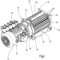
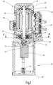
- the ones in the Fig. 2 The motor-pump device shown is designed as a modular system and has an electric motor designated as a whole by 10.
- the electric motor 10 can consist of a conventional asynchronous machine with an external stator 12 and an internal rotor 14 (see Fig. 2 ).
- the rotor 14 is connected in the usual way to a drive shaft 16 of the electric motor 10, which is rotatably mounted in bearing points 18 at the ends. Between the end bearing points 18 there is another third bearing point 20, which is accommodated on an inner wall in the multi-part motor housing 22 of the electric motor 10.
- the electric motor 10 can be equipped with or without a fan wheel; here in Fig. 1 and 2 shown with fan wheel.
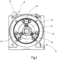
- a radial piston pump 24 is installed below the motor housing 22 with a total of three pump elements 26 as shown in the illustration Fig. 3 .
- three pistons or pump elements 26 six pistons or pump elements can also be used for the radial piston pump.
- the mentioned three or six valve spring-controlled radial piston pump elements 26 are actuated independently of the direction of rotation by an eccentric drive 28, which is driven by the external electric motor 10, namely via its drive shaft 16.
- Pump elements 26 shown are accommodated in a pump housing in the manner of an annular flange 30.
- This ring flange 30 is, like this in particular Fig. 2 shows, recorded between the electric motor 10 and a tank unit of the motor-pump device, designated as a whole by 32.
- the interior of the tank unit 32 serves to hold a predeterminable amount of oil fluid.
- a gear pump 34 is integrated within the tank unit 32, the technical structure of which is common and is therefore no longer shown in more detail. The gear pump 34 can be seen in the direction of view Fig.
- the radial piston pump 24 also has a suction line 38 with a filter element 39 for the purpose of filtering the oil removed from the tank 32 by means of the radial piston pump 24, which is also released from the hydraulic unit to the outside to a hydraulic consumer, as described at the beginning.
- the output shaft 42 of the gear pump 34 which is in the Fig. 2 is only shown in principle and schematically, is driven by the drive shaft 16 of the electric motor 10 via a so-called Oldham clutch 44.
- the nozzle-like fluid withdrawal parts including the suction lines 36 and 38, are designed in such a way that fluid can be withdrawn from the tank 32 both in a horizontal installation position of the unit as shown in FIG Fig. 1 can take place as well as a vertical elevation of the unit as shown in the illustration Fig. 2 is possible.
- the ventilation filter 40 To fill the tank 32, the ventilation filter 40 must be removed ( Fig. 1 , 3 ).
- the motor pump device can be equipped with radial piston pumps 24 and/or with gear pumps 34 in such a way that a pressure supply for hydraulic single and dual circuit systems is possible, only in low pressure (LP) or only in high pressure (HP) or corresponding to low pressure (LP) and high pressure (HP) combined with each other.
- the respective radial piston pump 24 should serve the high-pressure supply
- the gear pump 34 used should serve the low-pressure supply of a hydraulic circuit.
- it can be designed with two or four poles, and is that in the Fig. 1
- the unit shown is only intended for pure low-pressure applications in continuous operation Fig. 1
- Damping ring 46 shown from the outside between the annular flange 30 and the housing 22 of the electric motor 10 can also be omitted or replaced due to a different pump control.
- this can be supplied with high pressure (HP), low pressure (LP), high and low pressure (HN) and with low pressure/low pressure (NN).
- HP high pressure
- LP low pressure
- HN high and low pressure
- NN low pressure/low pressure
- HH high pressure/high pressure
- HN high/low pressure
- only one radial piston pump 24 can be used as a high-pressure pump or only one gear pump 34 can be used as a low-pressure pump according to the modular system presented here; otherwise all other structural components remain, as exemplified in the Fig. 2 presented, preserved.
- N; NN; NN Only with pure low-pressure variants (N; NN; NN) can a different motor-pump connection be used depending on the application.
- the high-pressure pump mentioned can provide a supply pressure of 700 bar with delivery rates of around 3l/minute.
- the low-pressure pump has a higher delivery rate of up to, for example, 8.6 l/min at 250 bar or, for example, 20 l/minute at 110 bar supply pressure. If two low-pressure supply pumps are combined with one another, in single-circuit operation (NN) one of the pumps can be switched to unpressurized circulation as required to save energy.
- the pumps in the dual-circuit system (NN; HN; HH) can be operated alternately or in parallel. The relevant values are only examples and can be adjusted accordingly depending on the application.
- an electrical connection box 50 is present on the outer circumference of the motor housing 22.
- At least one longitudinal linkage, designated as a whole by 48, including valves, is attached to the pump flange 30.
- a level indicator of the container contents can be integrated on a tank base 62 for the horizontal design and on the tank housing 52 for the vertical design.
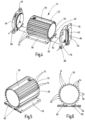
- the tank unit 32 is now shown in more detail. This is how it shows Fig. 4 the tank unit 32 in the manner of an exploded view with a housing 52, which is designed as an extruded profile, preferably made of aluminum. Along its outer circumference, the housing 52 has axially continuous cooling fins 54, which are an integral part of the extruded profile.
- the cooling fins 54 mentioned are interrupted by two flat profiles 56 and a flange plate 58 on the underside of the housing 52, viewed in the circumferential direction.
- the two flat profiles 56 can be used to carry an unspecified machine plate from the manufacturer and, as a further attachment, a level meter or sensor (not shown).
- the flange plate 58 serves to horizontally support the unit presented, as exemplified in the Fig. 1 is shown.
- the flange plate 58 mentioned is an integral part of the cylindrical housing body 52 of the tank unit 32 and is a hollow profile, as shown in particular in the illustrations 5 and 6 resulted, conceived.
- Two cooling channels 60 run along the tank unit 32 between the flange plate 58 and the cylindrical jacket of the housing 52.
- the housing 52 is accommodated between two add-on components 62, 64, which are viewed in the direction of the Fig. 4 Seen, right connection component (tank base) 62 on the stand of the unit as shown in the illustration Fig. 2 can serve or the flange 62 has an attachment on the bottom in the form of a fill level sensor 66, which then ensures a horizontal installation position of the unit, as in Fig. 1 presented, pretends.
- left connection component (tank adapter) 64 carries at its upper right end the filling neck 40 for the tank unit 32 and closes in succession, as in the Fig. 1 shown, to the annular flange 30 with the radial piston pump 24.
- the two flanges 62, 64 have connection points 68 with which a cooling circuit (not shown) can be implemented, in which, according to the arrow representations, the coolant enters at the connection point 68 of the tank base 62, is then forwarded to the two cooling channels 60 and collected by the tank adapter 64, the correspondingly heated coolant via the connection point 68, which in turn leaves the tank unit 32.
- a cooling circuit (not shown) can be implemented, in which, according to the arrow representations, the coolant enters at the connection point 68 of the tank base 62, is then forwarded to the two cooling channels 60 and collected by the tank adapter 64, the correspondingly heated coolant via the connection point 68, which in turn leaves the tank unit 32.
- the cooling fins 54 shown serve primarily for air and convection cooling of the tank contents
- the cooling channels 60 enable integrated liquid cooling for the tank contents of the tank unit 32.
- cooling lubricant As a cooling medium, since a Cooling lubricant supply is often already integrated as a unit in the machine tool.
- other cooling media such as water, glycol, etc. are also used. Due to the temperature difference, the cooling medium along the tank profile absorbs the heat of the oil container and thus also of the hydraulic oil that is stored in the tank unit 32.
- the coolant inlet is located at the tank base 62 and the outlet is at the tank adapter 64.
- This cooling process achieves saturation of the oil temperature below the permitted maximum temperature in certain applications.
- electric motors with appropriate operating modes are used. This solves the two thermal problem areas (oil temperature and engine temperature) of the hydraulic unit for the two operating modes mentioned.
- the hydraulic fluid is cooled very well and thus higher operating modes and duty cycles can be achieved with the unit in operation.
- These cooling methods are available both in horizontal ( Fig. 1 ) as well as vertically ( Fig. 2 ) Alignment of the unit can be used.
- the through holes 70 on the tank base 62 can also be provided with screw connections (not shown).
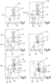
- Fig. 7 a low-pressure single-circuit system, wherein the gear pump 34 designed as a low-pressure pump feeds into a single supply connection P of the hydraulic single-circuit system, not shown.
- the fluid coming from the low-pressure system is returned via the tank connection T into the tank unit 32 for further removal.
- the removal takes place via the removal nozzle 36 and the low-pressure filter element 45 connected to it, so that the fluid then reaches the suction side of the gear pump 34.
- the connections P, T serve as an interface for fluid transfer to a linking system, not shown, of a hydraulic circuit, which is designed here as a single-circuit system.
- the gear pump 34 delivers the fluid on its pressure side to the supply port P of the single-circuit system.
- Fig. 8 is in this respect compared to the embodiment according to Fig. 7 changed as two low-pressure gear pumps 34 now supply a common supply connection P.
- one of the two pumps 34 can be switched to unpressurized circulation as required in order to save energy, work more efficiently and enable a variable volume flow at two operating points.
- a two-circuit system is implemented via the pressure supply connections P1, P2, once with high pressure (P1) and once with low pressure (P2).
- each supply connection P1, P2 being assigned its own supply line 72, which is supplied by the radial piston pump 24.
- a number of pistons, for example three pistons or pump elements 26 can be assigned to the circuit with the supply connection P1 and the remaining pistons or pump elements 26 then supply the second circuit via the further one Supply connection P2.
- the unit appears as a high-quality product with a clear visual order through obvious adjustments to the transitions of the components mentioned in a clearly structured form, which helps facilitate assembly and repair work.
- a very flexible modular system with a uniform structure is available.
- it can be more cost-effective to create a unit with a radial piston pump 24 and a gear pump 34 and, depending on requirements, to put only one of the two pumps 24, 34 or both pumps 24, 34 into operation than each to design an independent high or low pressure unit that only has a specially adapted supply pump.
Landscapes
- Engineering & Computer Science (AREA)
- Mechanical Engineering (AREA)
- General Engineering & Computer Science (AREA)
- Details Of Reciprocating Pumps (AREA)
Claims (11)
- Groupe motopompe, conçu en système modulaire, constitué d'au moins- un moteur (10) électrique, un rotor (14) du moteur (10) électrique étant relié à un arbre (16) d'entraînement de celui-ci, qui est monté tournant du côté de l'extrémité dans des points (18) d'appui, et dans lequel, entre les points (18) d'appui du côté de l'extrémité, il y a encore un autre troisième point (20) d'appui, qui, dans un carter (22) de moteur en plusieurs parties du moteur (10) électrique, est reçu sur une paroi intérieure,- une pompe (24) à pistons radiaux, chacune pouvant être entraînée par le moteur (10) électrique et servant, de préférence, d'alimentation sous haute pression et/ou une pompe (34) à engrenage, qui sert, de préférence, d'alimentation sous basse pression,- une unité (32) de réservoir, et- des pièces rapportées, comme des soupapes (48) en enchaînement longitudinal, et des mesureurs (66) de niveau, dans lequel, pour une réalisation d'un système hydraulique à un circuit ou à plusieurs circuits,- chaque pompe (24, 34) d'alimentation mise en oeuvre a un raccord (P1, P2) d'alimentation propre pour le circuit respectif du système mis en oeuvre, ou- plusieurs pompes (24, 34) d'alimentation utilisées refoulent dans un raccord (P) d'alimentation commun, ou- une pompe (24) d'alimentation unique, qui sert, de préférence, au refoulement sous haute pression, a plusieurs branches (72) d'alimentation, qui sont raccordées chacune à un raccord (P1, P2) d'alimentation, caractériséen ce que l'enveloppe (52) de l'unité (32) de réservoir, constituée sous la forme d'un profilé filé à la presse, est pourvue d'ailettes (54) de refroidissement s'étendant axialement le long de son pourtour extérieur tourné vers l'atmosphère ambiante, qui sont partie constitutive d'une seule pièce du profilé filé à la presse,en ce que l'enveloppe (52) de l'unité (32) de réservoir est constituée sous la forme d'une pièce cylindrique eten ce que, le long de son pourtour extérieur, est disposé un flasque (58), qui se transforme d'une seule pièce en la pièce cylindrique eten ce que ce flasque (58) permet le montage du groupe motopompe dans une position de montage horizontale et un pied (62) de réservoir permet la position de montage verticale.
- Groupe motopompe suivant la revendication 1, caractérisé en ce que la pompe (24) à pistons radiaux respective est reçue entre le moteur (10) électrique et l'unité (32) de réservoir.
- Groupe motopompe suivant la revendication 1 ou 2, caractérisé en ce que la pompe (34) à engrenage respective est reçue dans l'unité (32) de réservoir.
- Groupe motopompe suivant l'une des revendications précédentes, caractérisé en ce que le moteur (10) électrique entraîne, par l'arbre (16) d'entraînement commun, à la fois la pompe (24) à pistons radiaux et la pompe (34) à engrenage.
- Groupe motopompe suivant l'une des revendications précédentes, caractérisé en ce que le moteur (10) électrique a, se trouvant à l'extérieur, le carter (22) du moteur, qui se raccorde à l'atmosphère ambiante et auquel se raccorde l'enveloppe (30) de la pompe (24, 34) d'alimentation, à laquelle se raccorde à nouveau une enveloppe (52) de l'unité (32) de réservoir.
- Groupe motopompe suivant l'une des revendications précédentes, caractérisé en ce que le moteur (10) électrique, la pompe (24, 34) d'alimentation et l'unité (32) de réservoir sont les constituants essentiels du système modulaire.
- Groupe motopompe suivant l'une des revendications précédentes, caractérisé en ce que le moteur (10) électrique est une machine asynchrone ayant un stator (12) se trouvant à l'extérieur et le rotor (14) à l'intérieur.
- Groupe motopompe suivant l'une des revendications précédentes, caractérisé en ce qu'un enchaînement longitudinal de soupapes est fixé à la bride (30) de pompe.
- Groupe motopompe suivant l'une des revendications précédentes, caractérisé en ce que les pistons (26) de la pompe (24) à pistons radiaux peuvent être entraînés par un entraînement (28) à excentrique de l'arbre (16) d'entraînement du moteur (10) électrique et/ou en ce que l'arbre (42) de sortie de la pompe (34) à engrenage est relié par un accouplement (44) Oldham à l'arbre (16) d'entraînement du moteur (10) électrique.
- Groupe motopompe suivant l'une des revendications précédentes, caractérisé en ce que, intégré dans la surface latérale de l'enveloppe (52) de l'unité (32) de réservoir, il y a au moins un canal (60) de refroidissement, de préférence au point de transition entre le flasque (58) et la surface latérale cylindrique de l'enveloppe (52).
- Groupe motopompe suivant l'une des revendications précédentes, caractérisé en ce que l'enveloppe (52) de l'unité (32) de réservoir a, sur ses extrémités du côté frontal, d'une part le pied (62) du réservoir pour dresser le groupe motopompe dans une direction verticale, et d'autre part un autre adaptateur (64) de réservoir pour le raccordement de la bride (30) annulaire à la pompe (24) à pistons radiaux respective.
Applications Claiming Priority (2)
| Application Number | Priority Date | Filing Date | Title |
|---|---|---|---|
| DE102016010669.7A DE102016010669A1 (de) | 2016-08-29 | 2016-08-29 | Motor-Pumpenvorrichtung |
| PCT/EP2017/001026 WO2018041401A1 (fr) | 2016-08-29 | 2017-08-29 | Ensemble motopompe |
Publications (3)
| Publication Number | Publication Date |
|---|---|
| EP3504433A1 EP3504433A1 (fr) | 2019-07-03 |
| EP3504433B1 EP3504433B1 (fr) | 2020-04-22 |
| EP3504433B2 true EP3504433B2 (fr) | 2024-01-17 |
Family
ID=59791023
Family Applications (1)
| Application Number | Title | Priority Date | Filing Date |
|---|---|---|---|
| EP17761804.8A Active EP3504433B2 (fr) | 2016-08-29 | 2017-08-29 | Ensemble motopompe |
Country Status (3)
| Country | Link |
|---|---|
| EP (1) | EP3504433B2 (fr) |
| DE (1) | DE102016010669A1 (fr) |
| WO (1) | WO2018041401A1 (fr) |
Cited By (1)
| Publication number | Priority date | Publication date | Assignee | Title |
|---|---|---|---|---|
| DE102024126607A1 (de) * | 2024-09-16 | 2026-03-19 | HMS - Hybrid Motion Solutions GmbH | Adapter für Motorpumpeneinheit, Motorpumpeneinheit und Verfahren zum Betreiben |
Families Citing this family (9)
| Publication number | Priority date | Publication date | Assignee | Title |
|---|---|---|---|---|
| DE102018001725A1 (de) * | 2018-03-05 | 2019-09-05 | Hydac Fluidtechnik Gmbh | Anschlussvorrichtung |
| DE102018111059A1 (de) * | 2018-05-08 | 2019-11-14 | Speck-Kolbenpumpenfabrik Otto Speck Gmbh & Co Kg | Antrieb für eine kolbenpumpe oder einen -kompressor |
| FR3091561B1 (fr) * | 2019-01-03 | 2021-05-28 | Automatisation Et Controle Du Serrage | Microcentrale hydraulique |
| DE102019200703B4 (de) * | 2019-01-21 | 2026-02-05 | Hawe Hydraulik Se | Sensoreinheit, Fluidaggregat mit Sensoreinheit und Verfahren zur Messung von Parametern eines Fluids |
| DE102019206326A1 (de) * | 2019-05-03 | 2020-11-05 | Hawe Hydraulik Se | Pumpengehäuse mit Kühlmittelkanal und Pumpenaggregat |
| DE102019212074A1 (de) * | 2019-08-13 | 2021-02-18 | Robert Bosch Gmbh | Motor-Hydromaschinen-Einheit zum Anbau an ein Hydraulikaggregat |
| CN112032015A (zh) * | 2020-09-03 | 2020-12-04 | 王萍 | 一种逐步驱动式高效水泵 |
| CN115681067B (zh) * | 2022-09-30 | 2025-09-19 | 北京精密机电控制设备研究所 | 一种集驱动控制功能同轴一体化伺服电机泵 |
| CN120351138B (zh) * | 2025-06-25 | 2025-09-12 | 浙江大学 | 伺服电机泵紧凑容腔搅油流动特性的拟实测试装置及其综合测试平台 |
Citations (1)
| Publication number | Priority date | Publication date | Assignee | Title |
|---|---|---|---|---|
| CH596697A5 (en) † | 1975-05-26 | 1978-03-15 | Theodor Meier | Pump set with air-cooled flanged electric motor |
Family Cites Families (13)
| Publication number | Priority date | Publication date | Assignee | Title |
|---|---|---|---|---|
| DE2021210A1 (de) | 1970-04-30 | 1971-11-11 | Bbc Brown Boveri & Cie | Anordnung fuer den Anbau eines Elektromotors an eine Hydraulik-Pumpe |
| DE9405871U1 (de) | 1994-04-08 | 1994-06-01 | Heilmeier & Weinlein Fabrik für Oel-Hydraulik GmbH & Co KG, 81673 München | Hydraulisches Motorpumpenaggregat |
| DE19652706A1 (de) | 1995-12-22 | 1997-06-26 | Rexroth Mannesmann Gmbh | Hydraulisches Kompaktaggregat |
| DE19615053A1 (de) | 1996-04-17 | 1997-10-23 | Teves Gmbh Alfred | Elektromotor-/Pumpenaggregat |
| DE29609702U1 (de) | 1996-05-31 | 1996-08-29 | Fa. Ursula Schickedanz, 73033 Göppingen | Bügeleisen |
| DE29906881U1 (de) | 1999-04-16 | 1999-07-01 | Heilmeier & Weinlein | Elektrohydraulisches Motorpumpenaggregat |
| DE19942567A1 (de) | 1999-09-07 | 2001-03-22 | Fluidtech Gmbh | Vorrichtung zum Pumpen von Fluid |
| DE20007554U1 (de) | 2000-04-26 | 2000-08-10 | Heilmeier & Weinlein Fabrik für Oel-Hydraulik GmbH & Co KG, 81673 München | Motor-Pumpenaggregat |
| DE102004058624A1 (de) | 2004-12-04 | 2006-06-08 | Hydac Fluidtechnik Gmbh | Baukastensystem für Fluidpumpenvorrichtungen |
| EP2025934B1 (fr) | 2007-08-07 | 2009-08-05 | HAWE Hydraulik SE | Assemblage de pompes et de moteurs |
| ES2389633T3 (es) * | 2009-04-15 | 2012-10-29 | Hawe Hydraulik Se | Grupo motobomba |
| DE102014103958A1 (de) | 2014-03-21 | 2015-09-24 | Eckerle Industrie-Elektronik Gmbh | Motor-Pumpen-Einheit |
| DE102015115841B4 (de) | 2015-09-18 | 2024-04-18 | Schwäbische Hüttenwerke Automotive GmbH | Pumpen-Motor-Einheit mit einer Kühlung eines die Pumpe antreibenden Elektromotors mittels Leckagefluid |
-
2016
- 2016-08-29 DE DE102016010669.7A patent/DE102016010669A1/de not_active Withdrawn
-
2017
- 2017-08-29 EP EP17761804.8A patent/EP3504433B2/fr active Active
- 2017-08-29 WO PCT/EP2017/001026 patent/WO2018041401A1/fr not_active Ceased
Patent Citations (1)
| Publication number | Priority date | Publication date | Assignee | Title |
|---|---|---|---|---|
| CH596697A5 (en) † | 1975-05-26 | 1978-03-15 | Theodor Meier | Pump set with air-cooled flanged electric motor |
Cited By (1)
| Publication number | Priority date | Publication date | Assignee | Title |
|---|---|---|---|---|
| DE102024126607A1 (de) * | 2024-09-16 | 2026-03-19 | HMS - Hybrid Motion Solutions GmbH | Adapter für Motorpumpeneinheit, Motorpumpeneinheit und Verfahren zum Betreiben |
Also Published As
| Publication number | Publication date |
|---|---|
| EP3504433A1 (fr) | 2019-07-03 |
| EP3504433B1 (fr) | 2020-04-22 |
| DE102016010669A1 (de) | 2018-03-01 |
| WO2018041401A1 (fr) | 2018-03-08 |
Similar Documents
| Publication | Publication Date | Title |
|---|---|---|
| EP3504433B2 (fr) | Ensemble motopompe | |
| DE3820003C2 (fr) | ||
| EP1731762B1 (fr) | Ensemble de pompage | |
| DE10331216B3 (de) | Fluidkühlvorrichtung | |
| WO2015124248A2 (fr) | Groupe compact | |
| EP1574714B1 (fr) | Unité de pompage | |
| DE102020203459A1 (de) | Getriebeölfiltermodul | |
| EP1756434B1 (fr) | Unite modulaire | |
| DE29906881U1 (de) | Elektrohydraulisches Motorpumpenaggregat | |
| DE102020207028A1 (de) | Pumpeneinheit | |
| EP1633962A1 (fr) | Dispositif de refroidissement par liquide | |
| DE102004001268A1 (de) | Geberzylinder für Kupplungsausrücksysteme | |
| DE102004049883A1 (de) | Hydrauliksystem zur Bereitstellung einer Hilfskraft für eine Kraftfahrzeugeinrichtung | |
| EP2022990B1 (fr) | Machine outil et unité d'alimentation | |
| DE102007036032A1 (de) | Unterwassermotor mit Wärmetauscher | |
| EP1815204B1 (fr) | Echangeur thermique haute pression a faisceau de tubes | |
| EP1774152A1 (fr) | Module huile avec pompe a eau et echangeur de chaleur | |
| DE2331917A1 (de) | Pumpaggregat | |
| DE10256189A1 (de) | Hydraulisches Aggregat | |
| EP1717208B1 (fr) | Dispositif de traitement de fluides, en particulier de traitement des eaux usées, avec une pile de disques | |
| WO2013050099A1 (fr) | Agencement d'un module à huile et d'une pompe à huile sur un moteur à combustion interne | |
| WO2008062023A1 (fr) | Machine volumétrique rotative | |
| EP0465956B1 (fr) | Dispositif d'alimentation sous pression | |
| DE1628156A1 (de) | Gekapselter Motorverdichter,insbesondere fuer Kleinkaeltemaschinen | |
| DE102013211185A1 (de) | Spindelverdichter-Gehäuse |
Legal Events
| Date | Code | Title | Description |
|---|---|---|---|
| STAA | Information on the status of an ep patent application or granted ep patent |
Free format text: STATUS: UNKNOWN |
|
| STAA | Information on the status of an ep patent application or granted ep patent |
Free format text: STATUS: THE INTERNATIONAL PUBLICATION HAS BEEN MADE |
|
| PUAI | Public reference made under article 153(3) epc to a published international application that has entered the european phase |
Free format text: ORIGINAL CODE: 0009012 |
|
| STAA | Information on the status of an ep patent application or granted ep patent |
Free format text: STATUS: REQUEST FOR EXAMINATION WAS MADE |
|
| 17P | Request for examination filed |
Effective date: 20190329 |
|
| AK | Designated contracting states |
Kind code of ref document: A1 Designated state(s): AL AT BE BG CH CY CZ DE DK EE ES FI FR GB GR HR HU IE IS IT LI LT LU LV MC MK MT NL NO PL PT RO RS SE SI SK SM TR |
|
| AX | Request for extension of the european patent |
Extension state: BA ME |
|
| DAV | Request for validation of the european patent (deleted) | ||
| DAX | Request for extension of the european patent (deleted) | ||
| GRAP | Despatch of communication of intention to grant a patent |
Free format text: ORIGINAL CODE: EPIDOSNIGR1 |
|
| STAA | Information on the status of an ep patent application or granted ep patent |
Free format text: STATUS: GRANT OF PATENT IS INTENDED |
|
| INTG | Intention to grant announced |
Effective date: 20191217 |
|
| GRAS | Grant fee paid |
Free format text: ORIGINAL CODE: EPIDOSNIGR3 |
|
| GRAA | (expected) grant |
Free format text: ORIGINAL CODE: 0009210 |
|
| STAA | Information on the status of an ep patent application or granted ep patent |
Free format text: STATUS: THE PATENT HAS BEEN GRANTED |
|
| AK | Designated contracting states |
Kind code of ref document: B1 Designated state(s): AL AT BE BG CH CY CZ DE DK EE ES FI FR GB GR HR HU IE IS IT LI LT LU LV MC MK MT NL NO PL PT RO RS SE SI SK SM TR |
|
| REG | Reference to a national code |
Ref country code: CH Ref legal event code: EP |
|
| REG | Reference to a national code |
Ref country code: IE Ref legal event code: FG4D Free format text: LANGUAGE OF EP DOCUMENT: GERMAN |
|
| REG | Reference to a national code |
Ref country code: DE Ref legal event code: R096 Ref document number: 502017004900 Country of ref document: DE |
|
| REG | Reference to a national code |
Ref country code: AT Ref legal event code: REF Ref document number: 1260441 Country of ref document: AT Kind code of ref document: T Effective date: 20200515 |
|
| REG | Reference to a national code |
Ref country code: LT Ref legal event code: MG4D |
|
| REG | Reference to a national code |
Ref country code: NL Ref legal event code: MP Effective date: 20200422 |
|
| PG25 | Lapsed in a contracting state [announced via postgrant information from national office to epo] |
Ref country code: NO Free format text: LAPSE BECAUSE OF FAILURE TO SUBMIT A TRANSLATION OF THE DESCRIPTION OR TO PAY THE FEE WITHIN THE PRESCRIBED TIME-LIMIT Effective date: 20200722 Ref country code: LT Free format text: LAPSE BECAUSE OF FAILURE TO SUBMIT A TRANSLATION OF THE DESCRIPTION OR TO PAY THE FEE WITHIN THE PRESCRIBED TIME-LIMIT Effective date: 20200422 Ref country code: FI Free format text: LAPSE BECAUSE OF FAILURE TO SUBMIT A TRANSLATION OF THE DESCRIPTION OR TO PAY THE FEE WITHIN THE PRESCRIBED TIME-LIMIT Effective date: 20200422 Ref country code: NL Free format text: LAPSE BECAUSE OF FAILURE TO SUBMIT A TRANSLATION OF THE DESCRIPTION OR TO PAY THE FEE WITHIN THE PRESCRIBED TIME-LIMIT Effective date: 20200422 Ref country code: PT Free format text: LAPSE BECAUSE OF FAILURE TO SUBMIT A TRANSLATION OF THE DESCRIPTION OR TO PAY THE FEE WITHIN THE PRESCRIBED TIME-LIMIT Effective date: 20200824 Ref country code: IS Free format text: LAPSE BECAUSE OF FAILURE TO SUBMIT A TRANSLATION OF THE DESCRIPTION OR TO PAY THE FEE WITHIN THE PRESCRIBED TIME-LIMIT Effective date: 20200822 Ref country code: SE Free format text: LAPSE BECAUSE OF FAILURE TO SUBMIT A TRANSLATION OF THE DESCRIPTION OR TO PAY THE FEE WITHIN THE PRESCRIBED TIME-LIMIT Effective date: 20200422 Ref country code: GR Free format text: LAPSE BECAUSE OF FAILURE TO SUBMIT A TRANSLATION OF THE DESCRIPTION OR TO PAY THE FEE WITHIN THE PRESCRIBED TIME-LIMIT Effective date: 20200723 |
|
| PG25 | Lapsed in a contracting state [announced via postgrant information from national office to epo] |
Ref country code: RS Free format text: LAPSE BECAUSE OF FAILURE TO SUBMIT A TRANSLATION OF THE DESCRIPTION OR TO PAY THE FEE WITHIN THE PRESCRIBED TIME-LIMIT Effective date: 20200422 Ref country code: BG Free format text: LAPSE BECAUSE OF FAILURE TO SUBMIT A TRANSLATION OF THE DESCRIPTION OR TO PAY THE FEE WITHIN THE PRESCRIBED TIME-LIMIT Effective date: 20200722 Ref country code: LV Free format text: LAPSE BECAUSE OF FAILURE TO SUBMIT A TRANSLATION OF THE DESCRIPTION OR TO PAY THE FEE WITHIN THE PRESCRIBED TIME-LIMIT Effective date: 20200422 Ref country code: HR Free format text: LAPSE BECAUSE OF FAILURE TO SUBMIT A TRANSLATION OF THE DESCRIPTION OR TO PAY THE FEE WITHIN THE PRESCRIBED TIME-LIMIT Effective date: 20200422 |
|
| PG25 | Lapsed in a contracting state [announced via postgrant information from national office to epo] |
Ref country code: AL Free format text: LAPSE BECAUSE OF FAILURE TO SUBMIT A TRANSLATION OF THE DESCRIPTION OR TO PAY THE FEE WITHIN THE PRESCRIBED TIME-LIMIT Effective date: 20200422 |
|
| REG | Reference to a national code |
Ref country code: DE Ref legal event code: R026 Ref document number: 502017004900 Country of ref document: DE |
|
| PLBI | Opposition filed |
Free format text: ORIGINAL CODE: 0009260 |
|
| PG25 | Lapsed in a contracting state [announced via postgrant information from national office to epo] |
Ref country code: ES Free format text: LAPSE BECAUSE OF FAILURE TO SUBMIT A TRANSLATION OF THE DESCRIPTION OR TO PAY THE FEE WITHIN THE PRESCRIBED TIME-LIMIT Effective date: 20200422 Ref country code: DK Free format text: LAPSE BECAUSE OF FAILURE TO SUBMIT A TRANSLATION OF THE DESCRIPTION OR TO PAY THE FEE WITHIN THE PRESCRIBED TIME-LIMIT Effective date: 20200422 Ref country code: EE Free format text: LAPSE BECAUSE OF FAILURE TO SUBMIT A TRANSLATION OF THE DESCRIPTION OR TO PAY THE FEE WITHIN THE PRESCRIBED TIME-LIMIT Effective date: 20200422 Ref country code: CZ Free format text: LAPSE BECAUSE OF FAILURE TO SUBMIT A TRANSLATION OF THE DESCRIPTION OR TO PAY THE FEE WITHIN THE PRESCRIBED TIME-LIMIT Effective date: 20200422 Ref country code: RO Free format text: LAPSE BECAUSE OF FAILURE TO SUBMIT A TRANSLATION OF THE DESCRIPTION OR TO PAY THE FEE WITHIN THE PRESCRIBED TIME-LIMIT Effective date: 20200422 Ref country code: SM Free format text: LAPSE BECAUSE OF FAILURE TO SUBMIT A TRANSLATION OF THE DESCRIPTION OR TO PAY THE FEE WITHIN THE PRESCRIBED TIME-LIMIT Effective date: 20200422 Ref country code: IT Free format text: LAPSE BECAUSE OF FAILURE TO SUBMIT A TRANSLATION OF THE DESCRIPTION OR TO PAY THE FEE WITHIN THE PRESCRIBED TIME-LIMIT Effective date: 20200422 |
|
| PLAX | Notice of opposition and request to file observation + time limit sent |
Free format text: ORIGINAL CODE: EPIDOSNOBS2 |
|
| 26 | Opposition filed |
Opponent name: HAWE HYDRAULIK SE Effective date: 20210107 |
|
| PG25 | Lapsed in a contracting state [announced via postgrant information from national office to epo] |
Ref country code: SK Free format text: LAPSE BECAUSE OF FAILURE TO SUBMIT A TRANSLATION OF THE DESCRIPTION OR TO PAY THE FEE WITHIN THE PRESCRIBED TIME-LIMIT Effective date: 20200422 Ref country code: PL Free format text: LAPSE BECAUSE OF FAILURE TO SUBMIT A TRANSLATION OF THE DESCRIPTION OR TO PAY THE FEE WITHIN THE PRESCRIBED TIME-LIMIT Effective date: 20200422 |
|
| PG25 | Lapsed in a contracting state [announced via postgrant information from national office to epo] |
Ref country code: MC Free format text: LAPSE BECAUSE OF FAILURE TO SUBMIT A TRANSLATION OF THE DESCRIPTION OR TO PAY THE FEE WITHIN THE PRESCRIBED TIME-LIMIT Effective date: 20200422 |
|
| REG | Reference to a national code |
Ref country code: CH Ref legal event code: PL |
|
| PG25 | Lapsed in a contracting state [announced via postgrant information from national office to epo] |
Ref country code: CH Free format text: LAPSE BECAUSE OF NON-PAYMENT OF DUE FEES Effective date: 20200831 Ref country code: LU Free format text: LAPSE BECAUSE OF NON-PAYMENT OF DUE FEES Effective date: 20200829 Ref country code: LI Free format text: LAPSE BECAUSE OF NON-PAYMENT OF DUE FEES Effective date: 20200831 |
|
| PLBB | Reply of patent proprietor to notice(s) of opposition received |
Free format text: ORIGINAL CODE: EPIDOSNOBS3 |
|
| REG | Reference to a national code |
Ref country code: BE Ref legal event code: MM Effective date: 20200831 |
|
| PG25 | Lapsed in a contracting state [announced via postgrant information from national office to epo] |
Ref country code: SI Free format text: LAPSE BECAUSE OF FAILURE TO SUBMIT A TRANSLATION OF THE DESCRIPTION OR TO PAY THE FEE WITHIN THE PRESCRIBED TIME-LIMIT Effective date: 20200422 |
|
| PG25 | Lapsed in a contracting state [announced via postgrant information from national office to epo] |
Ref country code: BE Free format text: LAPSE BECAUSE OF NON-PAYMENT OF DUE FEES Effective date: 20200831 Ref country code: IE Free format text: LAPSE BECAUSE OF NON-PAYMENT OF DUE FEES Effective date: 20200829 |
|
| GBPC | Gb: european patent ceased through non-payment of renewal fee |
Effective date: 20210829 |
|
| PG25 | Lapsed in a contracting state [announced via postgrant information from national office to epo] |
Ref country code: TR Free format text: LAPSE BECAUSE OF FAILURE TO SUBMIT A TRANSLATION OF THE DESCRIPTION OR TO PAY THE FEE WITHIN THE PRESCRIBED TIME-LIMIT Effective date: 20200422 Ref country code: MT Free format text: LAPSE BECAUSE OF FAILURE TO SUBMIT A TRANSLATION OF THE DESCRIPTION OR TO PAY THE FEE WITHIN THE PRESCRIBED TIME-LIMIT Effective date: 20200422 Ref country code: CY Free format text: LAPSE BECAUSE OF FAILURE TO SUBMIT A TRANSLATION OF THE DESCRIPTION OR TO PAY THE FEE WITHIN THE PRESCRIBED TIME-LIMIT Effective date: 20200422 |
|
| PG25 | Lapsed in a contracting state [announced via postgrant information from national office to epo] |
Ref country code: MK Free format text: LAPSE BECAUSE OF FAILURE TO SUBMIT A TRANSLATION OF THE DESCRIPTION OR TO PAY THE FEE WITHIN THE PRESCRIBED TIME-LIMIT Effective date: 20200422 |
|
| PG25 | Lapsed in a contracting state [announced via postgrant information from national office to epo] |
Ref country code: GB Free format text: LAPSE BECAUSE OF NON-PAYMENT OF DUE FEES Effective date: 20210829 |
|
| REG | Reference to a national code |
Ref country code: AT Ref legal event code: MM01 Ref document number: 1260441 Country of ref document: AT Kind code of ref document: T Effective date: 20220829 |
|
| PG25 | Lapsed in a contracting state [announced via postgrant information from national office to epo] |
Ref country code: AT Free format text: LAPSE BECAUSE OF NON-PAYMENT OF DUE FEES Effective date: 20220829 |
|
| PUAH | Patent maintained in amended form |
Free format text: ORIGINAL CODE: 0009272 |
|
| STAA | Information on the status of an ep patent application or granted ep patent |
Free format text: STATUS: PATENT MAINTAINED AS AMENDED |
|
| 27A | Patent maintained in amended form |
Effective date: 20240117 |
|
| AK | Designated contracting states |
Kind code of ref document: B2 Designated state(s): AL AT BE BG CH CY CZ DE DK EE ES FI FR GB GR HR HU IE IS IT LI LT LU LV MC MK MT NL NO PL PT RO RS SE SI SK SM TR |
|
| REG | Reference to a national code |
Ref country code: DE Ref legal event code: R102 Ref document number: 502017004900 Country of ref document: DE |
|
| PGFP | Annual fee paid to national office [announced via postgrant information from national office to epo] |
Ref country code: DE Payment date: 20250831 Year of fee payment: 9 |
|
| PGFP | Annual fee paid to national office [announced via postgrant information from national office to epo] |
Ref country code: FR Payment date: 20250722 Year of fee payment: 9 |