EP3505703B1 - Système d'évacuation - Google Patents
Système d'évacuation Download PDFInfo
- Publication number
- EP3505703B1 EP3505703B1 EP19157327.8A EP19157327A EP3505703B1 EP 3505703 B1 EP3505703 B1 EP 3505703B1 EP 19157327 A EP19157327 A EP 19157327A EP 3505703 B1 EP3505703 B1 EP 3505703B1
- Authority
- EP
- European Patent Office
- Prior art keywords
- functional part
- build
- emergency overflow
- functional
- drain assembly
- Prior art date
- Legal status (The legal status is an assumption and is not a legal conclusion. Google has not performed a legal analysis and makes no representation as to the accuracy of the status listed.)
- Active
Links
Images




Classifications
-
- E—FIXED CONSTRUCTIONS
- E04—BUILDING
- E04D—ROOF COVERINGS; SKY-LIGHTS; GUTTERS; ROOF-WORKING TOOLS
- E04D13/00—Special arrangements or devices in connection with roof coverings; Protection against birds; Roof drainage ; Sky-lights
- E04D13/04—Roof drainage; Drainage fittings in flat roofs, balconies or the like
- E04D13/0404—Drainage on the roof surface
- E04D13/0409—Drainage outlets, e.g. gullies
-
- E—FIXED CONSTRUCTIONS
- E04—BUILDING
- E04D—ROOF COVERINGS; SKY-LIGHTS; GUTTERS; ROOF-WORKING TOOLS
- E04D13/00—Special arrangements or devices in connection with roof coverings; Protection against birds; Roof drainage ; Sky-lights
- E04D13/04—Roof drainage; Drainage fittings in flat roofs, balconies or the like
- E04D13/0404—Drainage on the roof surface
- E04D13/0409—Drainage outlets, e.g. gullies
- E04D2013/0413—Strainers for drainage outlets
Definitions
- the present invention relates to a drain arrangement for roof drainage comprising a drain device and an inlet device according to the preamble of claim 1.
- Drainage systems for surfaces such as flat roofs are known from the prior art. Such drainage systems include a pipe system through which the water lying on the surfaces is discharged. Typically, there is a negative pressure in the pipe system, which ensures fast and safe drainage.
- EP 2468979 A1 also discloses a generic drain arrangement with a drain device and an inlet device.
- the object of the invention is to specify a drain arrangement for roof drainage systems which overcomes the disadvantages of the prior art.
- a drainage device is to be specified which can be mounted as flexibly as possible.
- a drain arrangement for roof drainage comprises a drain device and an inlet device.
- the drain device has a pipe socket and at least one Retaining element, which is preferably connected to the pipe socket, on.
- the holding element could also be fixed in some other way, for example on the building side.
- the inlet device comprises a cover part for covering the pipe inlet with lateral passages through which water can be fed to the pipe inlet, and two functional parts which can be optionally arranged below the cover part.
- One of the functional parts is a storage function part that defines a storage height
- another of the functional parts is an emergency overflow function part with an inlet that defines an inlet height. Both the storage function part and the emergency overflow function part and the cover part can be fastened to said at least one holding element.
- the holding element thus serves to accommodate the accumulation function part and the cover part or the emergency overflow function part and the cover part.
- the pairing of storage function part and cover part and the pairing of emergency overflow function part and cover part can be fastened to the same holding element. This design is advantageous because there is no need to adapt the holding elements with regard to the function of the drain arrangement.
- the installer can decide on site whether the parts of the drain arrangement can be used as an emergency overflow or as a normal inlet.
- Both the accumulation function part and the emergency overflow function part are preferably held by the cover part on the holding element.
- the cover part serves as a fastening means for the storage function part and the emergency overflow function part to the holding element. Additional fastening elements can therefore be omitted.
- Exactly two holding elements are particularly preferably arranged diametrically opposite one another with respect to the pipe socket.
- a functional part can function as a backup function part or as an emergency overflow function part to be provided.
- the accumulation function part is designed differently than the emergency overflow function part.
- the cover part is identical in both cases. Consequently, there is the advantage that the inlet device is versatile, i.e. with the two functions "normal process” and “emergency process” can be provided, with only the corresponding functional part having to be selected.
- the cover part particularly preferably provides an interior space in which the functional part is located.
- the interior is accessible through said breakthroughs.
- the storage function part has at least one attachment interface for attaching the storage function part to the holding element and the emergency overflow function part has at least one attachment interface for attaching the emergency overflow function part to the holding element.
- Said attachment interface of the accumulation function part and the attachment interface of the emergency overflow function part are designed essentially identical to one another.
- the accumulation function part and the emergency overflow function part preferably have a disc-shaped base section, with the disk-shaped base section of the accumulation function part and that of the emergency overflow function part preferably being at the same level in the assembled state.
- the base section can include and/or accommodate and/or provide at least parts of the fastening interface.
- the attachment interface of the accumulation function part and the attachment interface of the emergency overflow part have the shape of an opening.
- several openings can be arranged.
- the number of holding elements preferably corresponds to the number of openings.
- the opening or openings are arranged in the same position and/or in the same position on the accumulation function part and on the emergency overflow function part.
- the opening is preferably arranged in the disc-shaped base section.
- the disc-shaped base section can be designed differently in the area of the opening.
- the disc-shaped base section is flat in the area of the opening.
- the disc-shaped base section has a bulge in the area of the opening, which bulge extends away from the cover part, with the opening being arranged in the bulge.
- the shape of the base section is changed by the bulge, whereby the shape of the holding element, which is mounted on the building side, can also be changed. If the bulge protrudes in the direction of the building, for example, the holding element can be made shorter, which is advantageous during assembly with regard to unintentional deformation by the installer.
- the bulge in the storage function part is preferably designed identically to the bulge in the emergency overflow function part.
- At least one fastening element is displaceably mounted on the cover part, with which fastening element the cover part can be fastened to the holding element.
- the fastening element can preferably be rotated about an axis.
- the number of fastening elements preferably corresponds to the number of holding elements.
- the fastening elements are preferably arranged in the same position and/or in the same position as the openings.
- the fastening element can be designed in one piece or in several pieces.
- the fastening element comprises an actuator part and a locking part which are connected to one another, with the actuator part being at least partially on top of the cover part and the locking part being at least partially on the underside of the cover part.
- the holding element is preferably designed as a pin with a notch, in particular a circumferential groove, it being possible for the cover part to be fastened to the holding element, in particular with the fastening element, via the notch
- the holding element preferably has a bearing surface on which the functional part is supported, in particular with the underside of the base section.
- the storage area is preferably arranged at a distance from the notch, which distance preferably corresponds to the thickness of the base portion.
- the functional part and the cover part preferably have alignment elements, in particular recesses and elevations, it being possible for the cover part to be aligned with the functional part via the alignment elements.
- Recesses are preferably arranged on the functional part and the webs, which delimit the openings on the cover part, serve as elevations.
- the base section preferably comprises a through-opening providing the inlet and an elevation which extends completely around the through-opening from the disc-shaped base section and whose upper edge defines the inlet height.
- the base section of the accumulation function part and the base section of the emergency overflow function part are essentially at the same level.
- the elevation is particularly preferably part of a pipe section, which extends from the upper edge of the elevation through the disk-shaped base section and protrudes into the pipe inlet of the drain pipe in the installed position.
- the storage function part is preferably arranged at a distance from the pipe socket, so that water can flow into the pipe socket through the distance. An intermediate space is thus created between the accumulation function part, in particular its base section, and the pipe inlet, through which the water can flow. Until the level of the accumulation function part is reached, the water flows normally with air into the pipe socket. As soon as the accumulation height is exceeded, the accumulation function part prevents further inflow of air into the pipe socket, which promotes the drainage of water.
- the emergency overflow function part is preferably arranged relative to the pipe socket in such a way that water can only flow into the pipe socket via the inlet of the emergency overflow function part. In particular, the piece of pipe of the emergency overflow functional part protrudes into the pipe socket. A seal is preferably arranged between the piece of pipe and the pipe socket.
- the storage function part serves to prevent air from entering the drain pipe when the water level on the building has reached or exceeded a storage level.
- the emergency overflow function part has an inlet defining an inlet height, with the emergency overflow function part providing an emergency outlet when the water level on the building exceeds the inlet height.
- the accumulation height of the accumulation function part is lower than or equal to the inlet height of the emergency overflow function part.
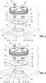
- FIG 1 a perspective view of a drain assembly 29 is shown.
- the outflow arrangement 29 comprises an outflow device 3 for the building drainage and an inlet device 1 which is arranged above the outflow device 3 .
- the water to be discharged is fed to the discharge device 3 via the inlet device 1 .
- Such a drain arrangement 29 shown in the figures is typically arranged in the building drainage on a roof. However, other areas that cannot be part of a building can also be drained.
- the building is only shown symbolically in the figures and bears the reference symbol G.
- FIGS. 2 and 3 show a sectional view of the outlet device 29.
- the inlet device 1 is shown in more detail. Based on Figures 2 and 3 the inlet device 1 will now be explained in more detail.
- the inlet device 1 comprises a cover part 4 for covering the pipe inlet 2 and a functional part 5 .
- the functional part 5 is arranged below the cover part 4 .
- the cover part 4 is provided with a multiplicity of lateral passages 21 through which water can be supplied to the drainage device 3 .
- the cover part 4 and the functional part 5 can be fastened to a holding element 6 of the drain device 3 mounted on the building side.
- the functional part 5 is either a storage function part 7 or an emergency overflow function part 8. In other words, the functional part 5 can be selected from the group of storage function part 7 and emergency overflow function part 8.
- a plurality of drain arrangement(s) 29 with the accumulation function part 7 and at least one or a plurality of drain arrangement(s) 29 with the emergency overflow function part 8 are arranged.
- the functional part 5 is shown as a storage function part 7 .
- the accumulation function part 7 is at a distance from the pipe inlet 2 of the discharge device 3 so that there is a free space 35 between the pipe inlet 2 and the accumulation function part 7 .
- the water to be discharged flows to the pipe inlet 2 through this free intermediate space 35 .
- the water flow is represented by the arrow W.
- the storage function part 7 serves to prevent air from entering the drain pipe 3 when the water level on the building has reached or exceeded a storage height S.
- the water level S is in the figure 2 marked with a dashed line.
- the inflow, here the intermediate space 37, to the pipe inlet 2 is completely filled with water and air can be prevented from entering the pipe inlet 2. Due to the resulting flow conditions, the discharge capacity can be increased.
- the emergency overflow functional part 8 includes an inlet 26 which defines an inlet height E.
- the emergency overflow function part 8 provides an emergency drain when the water level on the building G exceeds the inlet height E.
- the inlet height E is shown with a dashed line. Between the underside of the cover part 4 and the elevation 13 there is a free intermediate space 37 through which the water to be discharged can be fed to the inlet 26 .
- the storage height S of the storage function part 7 is, as in the Figures 2 and 3 shown, lower than or equal to the inlet height E of the emergency overflow function part 8. This means that until the inlet height E is reached, the water flows out via those drainage arrangements which are equipped with the storage function part 7 and when the inlet height E is exceeded, the water flows out via those drainage arrangements which are equipped with the emergency overflow function part 8.
- the cover part 4 comprises a cover section 39 of which a plurality of webs 38 extend laterally away.
- the webs 38 are arranged at a distance from one another.
- the passages 21 are created by the spacing.
- the accumulation function part 7 and the emergency overflow function part 8 each have at least one attachment interface 15, via which the respective function part 7, 8 can be attached to the holding element 6 of the drain device 3.
- the attachment interface of the accumulation function part 7 is essentially identical in design to the attachment interface of the emergency overflow function part 8 .
- both functional parts 7, 8 can be connected to the same holding elements 6. The installer can decide on site whether a storage function part 7 or an emergency overflow function part 8 should be arranged without having to make any adjustments to the holding elements 6 or the function parts 7, 8.
- both the accumulation function part 7 and the emergency overflow function part 8 have a disk-shaped base section 9 .
- the disk-shaped base section 9 of the accumulation function part 7 and that of the emergency overflow function part 8 are preferably at the same height.
- said attachment interface 15 is part of the base portion 9.
- the attachment interface 15 is shown here as openings extending through the base portion 9.
- the accumulation function part 7 or the emergency overflow function part 8 is mounted on the holding element 6 via these openings.
- the holding element 6 extends through the opening 15 .
- the accumulation height S is defined by the upper side 11 of the disc-shaped base section 9 .
- the water can therefore rise to the top 11 of the disc-shaped base section 9 and only then is the suction of air prevented.
- the base section 9 has a passage opening 10 providing the inlet 26 .
- the through-opening 10 is completed here by an elevation 12 which extends from the disc-shaped base section 9 surround.
- the elevation 12 essentially completely surrounds the passage opening 10 .
- the top edge 13 of the survey 12 defines the inlet height E.
- the survey 12 is part of a pipe section 14 here, which extends from the top edge 13 of the survey through the disc-shaped base section 9 and in the installed position, as in FIG figure 3 shown, in the pipe inlet 2 of the drain device 3 protrudes.
- the connection between pipe section 14 and raw inlet 2 is preferably designed to be watertight. The water flows along the arrow W through the passages 21 of the cover part 4 and then flows via the elevation 12 into the pipe section 14 and thus into the drain device 3 .
- the opening 15 is arranged in the base section 9 .
- the disk-shaped base section 9 is planar, ie flat, in the area of the opening 15 .
- the disc-shaped base section 9 is formed with a bulge 16 in the area of the opening 15 .
- the bulge 16 extends away from the cover part 4, ie in the direction of the drain device 3.
- the opening 15 is located at the base of the bulge 16 and is therefore arranged in the bulge 16.
- the bulge 16 has the advantage that the underside of the disc-shaped base section 9, which faces the drain device 3, is closer to the drain device 3.
- the holding elements 6 can be designed to be correspondingly shorter, which has the advantage during assembly that they can be pushed off less by tools or installers. This function is when comparing the length of the support members 6 between the Figures 4 and 5 and the Figures 6 to 9 apparently.
- the bulge 9 is arranged in such a way that it is surrounded by the base portion 9 .
- the bulge 9 is arranged in such a way that it is open with respect to the edge of the base section 9 .
- a fastener 17 mounted on the cover 4 slidably.
- the fastening element 17 is rotatably mounted here on the cover part 4 and can be brought from an unlocked position into a locked position.
- the fastening element 17 works together with the holding element 6 and secures the cover part 4 and the functional part 7, 8 to the holding element 6. In the locked position, the cover part 4 and the functional parts 7, 8 cannot be separated from the holding element 6.
- the two parts can be removed from the holding element 6 in the unlocked position.
- the fastening element 17 engages with a locking recess 36 in a groove 20 on the holding element 6, which here is in the form of a pin 19.
- the groove 20 can also be a notch that does not run all the way round.
- the cover part 4 is secured to the holding element 6 .
- the holding element 6 also includes a bearing surface 24 .
- the holding element 6 also protrudes through the opening 15 on the functional element 7 , 8 and the latter rests with its underside 25 on the bearing surface 24 . Due to the contact with the fastening element 17, the functional element 7, 8 is clamped between the bearing surface 24 and the fastening element 17 and is thus secured to the holding element 6.
- two fastening elements 17 are arranged. It would also be conceivable to provide only one or more than two fastening elements 17 .
- the number of holding elements 9 preferably corresponds to the number of fastening elements.
- the fastening elements 17 are designed in two parts.
- the fastening element 17 comprises an actuator part 22 and a locking part 23.
- the actuator part 22 is connected to the locking part 23.
- the actuator part 22 extends on the upper side to the cover part 4 and through the cover part 4 and is rotatably mounted in the cover part 4 .
- the actuator part 22 can be easily gripped by an installer.
- the locking part 23 is on the underside of the cover part 4 and works together with the holding element 6 .
- Actuator part 22 and locking part 23 are preferably connected to one another via a snap-in connection.
- the fastening element 17 can also be designed in one piece.
- the fastening element 17 has a grip tab 30 above the cover part 4 .
- the grip tab 30 can be grasped by the installer to operate the fastener.
- a comb 31 extends further from the upper side of the cover part 4.
- the comb 31 lies here between two fastening elements 17.
- the comb 31 and the gripping tabs 30 serve to signal the position of the fastening elements to the installer. If the grip tabs 30 are aligned with the comb, the fastening elements 17 are in the locked position. If the grip tab 30 is at an angle to the comb 31, the fastening element 17 is in the unlocked position.
- the fastening element 17 also has a nub 32 on the underside here.
- the nub 32 protrudes into a recess 33 in the base section 9 .
- the pairing of nubs 32 and recess 33 can provide guidance between the fastening element 17 and the accumulation function part 7 or the emergency overflow function part 8 .
- the guide helps when actuating the fastening element but also when positioning the cover part 4.
- an alignment element 27, 28 is provided from a pairing of elevation and recess.
- the elevation 27 is provided by the ridges 38 delimiting the passages 21 and the recess 28 extends into the base portion 9 from the edge.
- the drain device 3 comprises a pipe socket 18 and at least one holding element 6 connected to the pipe socket 18. In the embodiment shown, two holding elements 6 are shown in each case.
- the cover part 4 and the storage function part 7 or the emergency overflow function part 8 are fastened to the holding element 6 with the fastening element 17 .
- the storage function part 7 is arranged at a distance from the pipe socket 18 so that water can flow into the pipe socket 18 through this distance.
- the emergency overflow function part 8 is arranged relative to the pipe socket 18 in such a way that water can flow into the pipe socket 18 exclusively via the inlet 26 of the emergency overflow function part 8 .
- the accumulation function part 7 preferably has a flow-optimized shape.
- the accumulation function part 7 is designed accordingly on the underside, which faces the drainage device 3 .
- the flow-optimized elements bear the reference number 34.
Landscapes
- Engineering & Computer Science (AREA)
- Architecture (AREA)
- Civil Engineering (AREA)
- Structural Engineering (AREA)
- Sink And Installation For Waste Water (AREA)
Claims (14)
- Un agencement d'écoulement (29) pour le drainage de toitures, comprenant un dispositif d'écoulement (3) et un dispositif d'entrée (1),où le dispositif d'écoulement (3) possède un embout tubulaire (18) et au moins un élément de maintien (6), qui de préférence est en liaison avec l'embout tubulaire (18), etoù le dispositif d'entrée comprend une partie de recouvrement (4) servant à recouvrir l'entrée tubulaire (2) et munie de passages latéraux (21), à travers lesquels de l'eau peut être acheminée vers l'entrée tubulaire (2), et deux parties fonctionnelles (5), lesquelles peuvent être disposées en dessous de la partie de recouvrement (4),où une des parties fonctionnelles (5) est une partie fonctionnelle de retenue (7) définissant une hauteur de retenue (S) et où une autre des parties fonctionnelles (5) est une partie fonctionnelle de débordement de secours (8) munie d'une entrée (26) définissant une hauteur d'entrée (E), oùla partie fonctionnelle de retenue (7) ainsi que la partie fonctionnelle de débordement de secours (8) et la partie de recouvrement (4) peuvent être fixées audit au moins un élément de maintien (6), et où, au choix, la partie fonctionnelle de retenue (7) ou la partie fonctionnelle de débordement de secours (8) peuvent être insérées, etdans lequel la partie fonctionnelle de retenue (7) et la partie fonctionnelle de débordement de secours (8) présentent chacune au moins un interface de fixation (15), à travers lequel la partie fonctionnelle respective (5, 7, 8) peut être fixée à l'élément de maintien (6), où l'interface de fixation de la partie fonctionnelle de retenue (7) et l'interface de fixation de la partie fonctionnelle de débordement de secours (8) sont réalisés sensiblement identiques l'un par rapport à l'autre.
- Agencement d'écoulement (29) selon la revendication 1, caractérisé en ce que la partie fonctionnelle de retenue (7) ainsi que la partie fonctionnelle de débordement de secours (8) sont maintenues par la partie de recouvrement sur l'élément de maintien (6).
- Agencement d'écoulement (29) selon l'une des revendications précédentes, caractérisé en ce que la partie fonctionnelle de retenue (7) et la partie fonctionnelle de débordement de secours (8) présentent chacune une section de base en forme de disque (9), dans lequel, à l'état assemblé, la section de base en forme de disque (9) de la partie fonctionnelle de retenue (7) et celle de la partie fonctionnelle de débordement de secours (8) sont situées de préférence au même niveau.
- Agencement d'écoulement (29) selon la revendication 3, caractérisé en ce que la section de base (9) peut comprendre et / ou recevoir et / ou fournir au moins des parties de l'interface de fixation (15).
- Agencement d'écoulement (29) selon l'une des revendications précédentes, caractérisé en ce que l'interface de fixation de la partie fonctionnelle de retenue et l'interface de fixation la partie fonctionnelle de débordement de secours ont la forme d'une ouverture (15) qui, au niveau de la partie fonctionnelle de retenue (7) et de partie fonctionnelle de débordement de secours (8) est disposée dans la même position resp. dans la même orientation.
- Agencement d'écoulement (29) selon la revendication 5, caractérisé en ce que l'ouverture (15) est disposée dans la section de base en forme de disque (9), où la section de base en forme de disque (9) est agencée de manière plate dans la région de l'ouverture (15) ou où la section de base en forme de disque (9), dans la région de l'ouverture (15), présente un renflement (16) qui s'éloigne de partie de recouvrement (4), où l'ouverture (15) est agencée dans le renflement (16).
- Agencement d'écoulement (29) selon l'une des revendications précédentes, caractérisé en ce que au moins un élément de fixation (17) est monté de manière déplaçable sur la partie de recouvrement (4), avec lequel élément de fixation (17) la partie de recouvrement (4) peut être fixée à l'élément de maintien (6).
- Agencement d'écoulement (29) selon la revendication 7, caractérisé en ce que l'élément de fixation (17) est formé d'une ou de plusieurs pièces avec une partie actionneur (22) et une partie de verrouillage (23), lesquelles sont reliées entre elles, dans lequel la partie actionneur (22) se situe au moins partiellement sur le dessus de la partie de recouvrement (4) et la partie de verrouillage (23) se situe au moins partiellement sur le dessous de la partie de recouvrement (4).
- Agencement d'écoulement (29) selon une des revendications précédentes, caractérisé en ce que l'élément de maintien (9) est formé en tant que tenon (19) avec une encoche, en particulier avec une rainure circonférentielle (20), dans lequel la partie de recouvrement (4), en particulier avec l'élément de fixation (17), peut être fixée via l'encoche à l'élément de maintien.
- Agencement d'écoulement (29) selon une des revendications précédentes, en particulier selon la revendication 9, caractérisé en ce que l'élément de maintien (9) présente une surface d'appui (24) sur laquelle repose la partie fonctionnelle (5), en particulier avec la face inférieure (25) de la section de base (9), où la surface d'appui (24) est disposée à une distance de l'encoche (20), qui correspond de préférence à l'épaisseur de la section de base (9).
- Agencement d'écoulement (29) selon une des revendications précédentes, caractérisé en ce que la partie fonctionnelle (5, 7, 8) et la partie de recouvrement (4) présentent des éléments d'alignement (27, 28), en particulier des évidements (27) et des élévations (28), dans lequel la partie de recouvrement (4) peut être alignée vers la partie fonctionnelle (5, 7, 8) via les éléments d'alignement (27, 28).
- Agencement d'écoulement (29) selon une des revendications précédentes, caractérisé en ceque au niveau de la partie fonctionnelle de retenue (7), le dessus (11) de la section de base en forme de disque (9) définit la hauteur de retenue (S) et / ouque la partie fonctionnelle de débordement de secours (8) et la section de base (9) comporte une ouverture de passage (10) constituant l'entrée (26) et une élévation (12) s'étendant complètement autour de l'ouverture de passage (10) à partir de la section de base en forme de disque (9), dont le bord supérieur (13) définit la hauteur d'entrée.
- Agencement d'écoulement (29) selon la revendication 12, caractérisé en ce que l'élévation (12) fait partie d'une section de tuyau (14), laquelle s'étend du bord supérieur (13) de l'élévation (12) à travers la section de base en forme de disque (9) et, en position d'installation, fait saillie dans l'entrée tubulaire (2) du dispositif d'écoulement (3).
- Agencement d'écoulement (29) selon la revendication 12 ou 13, caractérisé en ce qu'entre la face inférieure de la partie de recouvrement (4) et l'élévation (26) un espace libre (37) existe, à travers lequel l'eau à évacuer peut être acheminée vers l'entrée (26) et / ouque la partie fonctionnelle de retenue (7) est disposée de manière espacée de l'embout tubulaire (18) de sorte qu'entre l'entrée tubulaire (2) et le disque de retenue, un espace libre (35) est créé, à travers lequel l'eau peut s'écouler vers l'embout tubulaire (18) et / ouque la partie fonctionnelle de débordement de secours (8) est disposée de telle manière par rapport à l'embout tubulaire (18) que l'eau ne peut que s'écouler vers l'embout tubulaire à travers l'entrée (26) de la partie fonctionnelle de débordement de secours (8).
Priority Applications (3)
| Application Number | Priority Date | Filing Date | Title |
|---|---|---|---|
| EP19157327.8A EP3505703B1 (fr) | 2015-06-12 | 2015-06-12 | Système d'évacuation |
| DK19157327.8T DK3505703T3 (da) | 2015-06-12 | 2015-06-12 | Afløbsanordning |
| PL19157327T PL3505703T3 (pl) | 2015-06-12 | 2015-06-12 | Układ odpływowy |
Applications Claiming Priority (2)
| Application Number | Priority Date | Filing Date | Title |
|---|---|---|---|
| EP19157327.8A EP3505703B1 (fr) | 2015-06-12 | 2015-06-12 | Système d'évacuation |
| EP15171865.7A EP3103937B1 (fr) | 2015-06-12 | 2015-06-12 | Agencement de drainage |
Related Parent Applications (2)
| Application Number | Title | Priority Date | Filing Date |
|---|---|---|---|
| EP15171865.7A Division EP3103937B1 (fr) | 2015-06-12 | 2015-06-12 | Agencement de drainage |
| EP15171865.7A Division-Into EP3103937B1 (fr) | 2015-06-12 | 2015-06-12 | Agencement de drainage |
Publications (2)
| Publication Number | Publication Date |
|---|---|
| EP3505703A1 EP3505703A1 (fr) | 2019-07-03 |
| EP3505703B1 true EP3505703B1 (fr) | 2022-01-26 |
Family
ID=53397912
Family Applications (2)
| Application Number | Title | Priority Date | Filing Date |
|---|---|---|---|
| EP19157327.8A Active EP3505703B1 (fr) | 2015-06-12 | 2015-06-12 | Système d'évacuation |
| EP15171865.7A Active EP3103937B1 (fr) | 2015-06-12 | 2015-06-12 | Agencement de drainage |
Family Applications After (1)
| Application Number | Title | Priority Date | Filing Date |
|---|---|---|---|
| EP15171865.7A Active EP3103937B1 (fr) | 2015-06-12 | 2015-06-12 | Agencement de drainage |
Country Status (6)
| Country | Link |
|---|---|
| EP (2) | EP3505703B1 (fr) |
| CN (1) | CN107646059A (fr) |
| AU (1) | AU2016274373B2 (fr) |
| DK (2) | DK3505703T3 (fr) |
| PL (2) | PL3505703T3 (fr) |
| WO (1) | WO2016198234A1 (fr) |
Families Citing this family (1)
| Publication number | Priority date | Publication date | Assignee | Title |
|---|---|---|---|---|
| US10907356B2 (en) * | 2018-06-19 | 2021-02-02 | RPH Intellectual Holdings, LLC | Roof drain |
Family Cites Families (6)
| Publication number | Priority date | Publication date | Assignee | Title |
|---|---|---|---|---|
| US1762838A (en) * | 1929-01-23 | 1930-06-10 | Shand & Jurs Company | Roof drain |
| US2121220A (en) * | 1936-12-18 | 1938-06-21 | Paul Dickinson Inc | Roof drain |
| EP1013843B1 (fr) * | 1998-12-24 | 2003-08-20 | Wolfgang Dipl.-Ing. Vahlbrauk | Evacuation d'eau à écoulement libre |
| IT1395999B1 (it) * | 2009-03-10 | 2012-11-09 | Valsir Spa | Pozzetto di scarico d'acqua, in particolare per sistemi ad effetto sifonico di drenaggio dei tetti |
| IT1403885B1 (it) * | 2010-11-26 | 2013-11-08 | Valsir Spa | Dispositivo di trabocco per pozzetti di scarico d'acqua, in particolare per sistemi di drenaggio di coperture di edifici, e pozzetto di scarico d'acqua provvisto di tale dispositivo di trabocco |
| PL2703576T3 (pl) * | 2012-09-03 | 2015-11-30 | Geberit Int Ag | Urządzenia do przykrywania osłony rurowej wlotu elementu przepływowego układu odwadniającego |
-
2015
- 2015-06-12 DK DK19157327.8T patent/DK3505703T3/da active
- 2015-06-12 EP EP19157327.8A patent/EP3505703B1/fr active Active
- 2015-06-12 PL PL19157327T patent/PL3505703T3/pl unknown
- 2015-06-12 EP EP15171865.7A patent/EP3103937B1/fr active Active
- 2015-06-12 DK DK15171865.7T patent/DK3103937T3/da active
- 2015-06-12 PL PL15171865T patent/PL3103937T3/pl unknown
-
2016
- 2016-05-13 AU AU2016274373A patent/AU2016274373B2/en active Active
- 2016-05-13 CN CN201680029898.2A patent/CN107646059A/zh active Pending
- 2016-05-13 WO PCT/EP2016/060877 patent/WO2016198234A1/fr not_active Ceased
Non-Patent Citations (1)
| Title |
|---|
| None * |
Also Published As
| Publication number | Publication date |
|---|---|
| EP3505703A1 (fr) | 2019-07-03 |
| WO2016198234A1 (fr) | 2016-12-15 |
| CN107646059A (zh) | 2018-01-30 |
| EP3103937A1 (fr) | 2016-12-14 |
| DK3505703T3 (da) | 2022-04-19 |
| EP3103937B1 (fr) | 2020-01-01 |
| PL3505703T3 (pl) | 2022-04-25 |
| AU2016274373B2 (en) | 2021-08-05 |
| AU2016274373A1 (en) | 2017-11-16 |
| DK3103937T3 (da) | 2020-03-30 |
| PL3103937T3 (pl) | 2020-06-29 |
Similar Documents
| Publication | Publication Date | Title |
|---|---|---|
| DE112009005518B4 (de) | Positionskompensierende Fahrzeugdachrinnen-Formteilhaltevorrichtung | |
| EP0442135B1 (fr) | Dispositif pour réunir plusieurs infusions et/ou injections | |
| EP3024990B1 (fr) | Bouche d'egout | |
| DE202004015811U1 (de) | Befestigungsvorrichtung für mindestens einen Sonnenkollektor | |
| DE102014101320A1 (de) | Entwässerungsabdeckung | |
| DE102015109900B4 (de) | Unterflasche, insbesondere für Seilzüge, und Montageverfahren für ein Abdeckelement an der Seilflasche | |
| EP3505703B1 (fr) | Système d'évacuation | |
| WO2021105104A1 (fr) | Système de gouttière, unité de couvercle et élément de fixation | |
| EP4283059B1 (fr) | Boîtier de pose destiné au logement d'une robinetterie d'écoulement | |
| EP3272955B1 (fr) | Systeme de siphon | |
| EP3202990A1 (fr) | Pistolet | |
| EP1826334B1 (fr) | Déversoir de secours | |
| EP2703576B1 (fr) | Dispositif de recouvrement destiné au recouvrement de l'entrée du tube d'un élément d'écoulement d'un système de drainage | |
| WO2014037413A1 (fr) | Ensemble de vidange et procédé pour disposer un ensemble de vidange sur une bride de vidange d'une cuvette | |
| EP3272954B1 (fr) | Système d'évacuation | |
| DE202009007897U1 (de) | Wasserrohrmuffe | |
| DE29815492U1 (de) | Verbessertes Schraubelement | |
| EP2981241B1 (fr) | Dispositif de soupape et de liaison fluidique | |
| DE102021111651B4 (de) | Abflussfilter | |
| EP2641306B1 (fr) | Dispositif formant goulotte d'expulsion pour un limiteur de surtension, limiteur de surtension et jeu de limiteurs de surtensions montés en série | |
| EP3502367B1 (fr) | Goutièrre d'écoulement | |
| DE102010034549B4 (de) | Verschlussvorrichtung | |
| DE102015102348B4 (de) | Vorrichtungslüfterabdeckung | |
| DE20318617U1 (de) | Einlaufgehäuse | |
| EP0798475B1 (fr) | Elément pour la fixation d'un tapis |
Legal Events
| Date | Code | Title | Description |
|---|---|---|---|
| PUAI | Public reference made under article 153(3) epc to a published international application that has entered the european phase |
Free format text: ORIGINAL CODE: 0009012 |
|
| STAA | Information on the status of an ep patent application or granted ep patent |
Free format text: STATUS: THE APPLICATION HAS BEEN PUBLISHED |
|
| AC | Divisional application: reference to earlier application |
Ref document number: 3103937 Country of ref document: EP Kind code of ref document: P |
|
| AK | Designated contracting states |
Kind code of ref document: A1 Designated state(s): AL AT BE BG CH CY CZ DE DK EE ES FI FR GB GR HR HU IE IS IT LI LT LU LV MC MK MT NL NO PL PT RO RS SE SI SK SM TR |
|
| STAA | Information on the status of an ep patent application or granted ep patent |
Free format text: STATUS: REQUEST FOR EXAMINATION WAS MADE |
|
| 17P | Request for examination filed |
Effective date: 20191108 |
|
| RBV | Designated contracting states (corrected) |
Designated state(s): AL AT BE BG CH CY CZ DE DK EE ES FI FR GB GR HR HU IE IS IT LI LT LU LV MC MK MT NL NO PL PT RO RS SE SI SK SM TR |
|
| STAA | Information on the status of an ep patent application or granted ep patent |
Free format text: STATUS: EXAMINATION IS IN PROGRESS |
|
| 17Q | First examination report despatched |
Effective date: 20200128 |
|
| GRAP | Despatch of communication of intention to grant a patent |
Free format text: ORIGINAL CODE: EPIDOSNIGR1 |
|
| STAA | Information on the status of an ep patent application or granted ep patent |
Free format text: STATUS: GRANT OF PATENT IS INTENDED |
|
| RIN1 | Information on inventor provided before grant (corrected) |
Inventor name: HAUSHEER, ROMAN |
|
| INTG | Intention to grant announced |
Effective date: 20210709 |
|
| GRAJ | Information related to disapproval of communication of intention to grant by the applicant or resumption of examination proceedings by the epo deleted |
Free format text: ORIGINAL CODE: EPIDOSDIGR1 |
|
| STAA | Information on the status of an ep patent application or granted ep patent |
Free format text: STATUS: EXAMINATION IS IN PROGRESS |
|
| GRAP | Despatch of communication of intention to grant a patent |
Free format text: ORIGINAL CODE: EPIDOSNIGR1 |
|
| STAA | Information on the status of an ep patent application or granted ep patent |
Free format text: STATUS: GRANT OF PATENT IS INTENDED |
|
| GRAS | Grant fee paid |
Free format text: ORIGINAL CODE: EPIDOSNIGR3 |
|
| GRAA | (expected) grant |
Free format text: ORIGINAL CODE: 0009210 |
|
| STAA | Information on the status of an ep patent application or granted ep patent |
Free format text: STATUS: THE PATENT HAS BEEN GRANTED |
|
| INTG | Intention to grant announced |
Effective date: 20211203 |
|
| AC | Divisional application: reference to earlier application |
Ref document number: 3103937 Country of ref document: EP Kind code of ref document: P |
|
| AK | Designated contracting states |
Kind code of ref document: B1 Designated state(s): AL AT BE BG CH CY CZ DE DK EE ES FI FR GB GR HR HU IE IS IT LI LT LU LV MC MK MT NL NO PL PT RO RS SE SI SK SM TR |
|
| REG | Reference to a national code |
Ref country code: GB Ref legal event code: FG4D Free format text: NOT ENGLISH |
|
| REG | Reference to a national code |
Ref country code: CH Ref legal event code: EP |
|
| REG | Reference to a national code |
Ref country code: AT Ref legal event code: REF Ref document number: 1465409 Country of ref document: AT Kind code of ref document: T Effective date: 20220215 |
|
| REG | Reference to a national code |
Ref country code: IE Ref legal event code: FG4D Free format text: LANGUAGE OF EP DOCUMENT: GERMAN |
|
| REG | Reference to a national code |
Ref country code: DE Ref legal event code: R096 Ref document number: 502015015614 Country of ref document: DE |
|
| REG | Reference to a national code |
Ref country code: FI Ref legal event code: FGE |
|
| REG | Reference to a national code |
Ref country code: SE Ref legal event code: TRGR |
|
| REG | Reference to a national code |
Ref country code: NL Ref legal event code: FP |
|
| REG | Reference to a national code |
Ref country code: DK Ref legal event code: T3 Effective date: 20220411 |
|
| REG | Reference to a national code |
Ref country code: LT Ref legal event code: MG9D |
|
| PG25 | Lapsed in a contracting state [announced via postgrant information from national office to epo] |
Ref country code: RS Free format text: LAPSE BECAUSE OF FAILURE TO SUBMIT A TRANSLATION OF THE DESCRIPTION OR TO PAY THE FEE WITHIN THE PRESCRIBED TIME-LIMIT Effective date: 20220126 Ref country code: PT Free format text: LAPSE BECAUSE OF FAILURE TO SUBMIT A TRANSLATION OF THE DESCRIPTION OR TO PAY THE FEE WITHIN THE PRESCRIBED TIME-LIMIT Effective date: 20220526 Ref country code: NO Free format text: LAPSE BECAUSE OF FAILURE TO SUBMIT A TRANSLATION OF THE DESCRIPTION OR TO PAY THE FEE WITHIN THE PRESCRIBED TIME-LIMIT Effective date: 20220426 Ref country code: LT Free format text: LAPSE BECAUSE OF FAILURE TO SUBMIT A TRANSLATION OF THE DESCRIPTION OR TO PAY THE FEE WITHIN THE PRESCRIBED TIME-LIMIT Effective date: 20220126 Ref country code: HR Free format text: LAPSE BECAUSE OF FAILURE TO SUBMIT A TRANSLATION OF THE DESCRIPTION OR TO PAY THE FEE WITHIN THE PRESCRIBED TIME-LIMIT Effective date: 20220126 Ref country code: ES Free format text: LAPSE BECAUSE OF FAILURE TO SUBMIT A TRANSLATION OF THE DESCRIPTION OR TO PAY THE FEE WITHIN THE PRESCRIBED TIME-LIMIT Effective date: 20220126 Ref country code: BG Free format text: LAPSE BECAUSE OF FAILURE TO SUBMIT A TRANSLATION OF THE DESCRIPTION OR TO PAY THE FEE WITHIN THE PRESCRIBED TIME-LIMIT Effective date: 20220426 |
|
| PG25 | Lapsed in a contracting state [announced via postgrant information from national office to epo] |
Ref country code: LV Free format text: LAPSE BECAUSE OF FAILURE TO SUBMIT A TRANSLATION OF THE DESCRIPTION OR TO PAY THE FEE WITHIN THE PRESCRIBED TIME-LIMIT Effective date: 20220126 Ref country code: GR Free format text: LAPSE BECAUSE OF FAILURE TO SUBMIT A TRANSLATION OF THE DESCRIPTION OR TO PAY THE FEE WITHIN THE PRESCRIBED TIME-LIMIT Effective date: 20220427 |
|
| PG25 | Lapsed in a contracting state [announced via postgrant information from national office to epo] |
Ref country code: IS Free format text: LAPSE BECAUSE OF FAILURE TO SUBMIT A TRANSLATION OF THE DESCRIPTION OR TO PAY THE FEE WITHIN THE PRESCRIBED TIME-LIMIT Effective date: 20220526 |
|
| REG | Reference to a national code |
Ref country code: DE Ref legal event code: R097 Ref document number: 502015015614 Country of ref document: DE |
|
| PG25 | Lapsed in a contracting state [announced via postgrant information from national office to epo] |
Ref country code: SM Free format text: LAPSE BECAUSE OF FAILURE TO SUBMIT A TRANSLATION OF THE DESCRIPTION OR TO PAY THE FEE WITHIN THE PRESCRIBED TIME-LIMIT Effective date: 20220126 Ref country code: SK Free format text: LAPSE BECAUSE OF FAILURE TO SUBMIT A TRANSLATION OF THE DESCRIPTION OR TO PAY THE FEE WITHIN THE PRESCRIBED TIME-LIMIT Effective date: 20220126 Ref country code: RO Free format text: LAPSE BECAUSE OF FAILURE TO SUBMIT A TRANSLATION OF THE DESCRIPTION OR TO PAY THE FEE WITHIN THE PRESCRIBED TIME-LIMIT Effective date: 20220126 Ref country code: EE Free format text: LAPSE BECAUSE OF FAILURE TO SUBMIT A TRANSLATION OF THE DESCRIPTION OR TO PAY THE FEE WITHIN THE PRESCRIBED TIME-LIMIT Effective date: 20220126 Ref country code: CZ Free format text: LAPSE BECAUSE OF FAILURE TO SUBMIT A TRANSLATION OF THE DESCRIPTION OR TO PAY THE FEE WITHIN THE PRESCRIBED TIME-LIMIT Effective date: 20220126 |
|
| PG25 | Lapsed in a contracting state [announced via postgrant information from national office to epo] |
Ref country code: AL Free format text: LAPSE BECAUSE OF FAILURE TO SUBMIT A TRANSLATION OF THE DESCRIPTION OR TO PAY THE FEE WITHIN THE PRESCRIBED TIME-LIMIT Effective date: 20220126 |
|
| PLBE | No opposition filed within time limit |
Free format text: ORIGINAL CODE: 0009261 |
|
| STAA | Information on the status of an ep patent application or granted ep patent |
Free format text: STATUS: NO OPPOSITION FILED WITHIN TIME LIMIT |
|
| 26N | No opposition filed |
Effective date: 20221027 |
|
| PG25 | Lapsed in a contracting state [announced via postgrant information from national office to epo] |
Ref country code: MC Free format text: LAPSE BECAUSE OF FAILURE TO SUBMIT A TRANSLATION OF THE DESCRIPTION OR TO PAY THE FEE WITHIN THE PRESCRIBED TIME-LIMIT Effective date: 20220126 |
|
| REG | Reference to a national code |
Ref country code: BE Ref legal event code: MM Effective date: 20220630 |
|
| PG25 | Lapsed in a contracting state [announced via postgrant information from national office to epo] |
Ref country code: SI Free format text: LAPSE BECAUSE OF FAILURE TO SUBMIT A TRANSLATION OF THE DESCRIPTION OR TO PAY THE FEE WITHIN THE PRESCRIBED TIME-LIMIT Effective date: 20220126 |
|
| GBPC | Gb: european patent ceased through non-payment of renewal fee |
Effective date: 20220612 |
|
| PG25 | Lapsed in a contracting state [announced via postgrant information from national office to epo] |
Ref country code: LU Free format text: LAPSE BECAUSE OF NON-PAYMENT OF DUE FEES Effective date: 20220612 Ref country code: IE Free format text: LAPSE BECAUSE OF NON-PAYMENT OF DUE FEES Effective date: 20220612 Ref country code: FR Free format text: LAPSE BECAUSE OF NON-PAYMENT OF DUE FEES Effective date: 20220630 |
|
| PG25 | Lapsed in a contracting state [announced via postgrant information from national office to epo] |
Ref country code: GB Free format text: LAPSE BECAUSE OF NON-PAYMENT OF DUE FEES Effective date: 20220612 Ref country code: BE Free format text: LAPSE BECAUSE OF NON-PAYMENT OF DUE FEES Effective date: 20220630 |
|
| P01 | Opt-out of the competence of the unified patent court (upc) registered |
Effective date: 20230516 |
|
| PG25 | Lapsed in a contracting state [announced via postgrant information from national office to epo] |
Ref country code: HU Free format text: LAPSE BECAUSE OF FAILURE TO SUBMIT A TRANSLATION OF THE DESCRIPTION OR TO PAY THE FEE WITHIN THE PRESCRIBED TIME-LIMIT; INVALID AB INITIO Effective date: 20150612 |
|
| PG25 | Lapsed in a contracting state [announced via postgrant information from national office to epo] |
Ref country code: MK Free format text: LAPSE BECAUSE OF FAILURE TO SUBMIT A TRANSLATION OF THE DESCRIPTION OR TO PAY THE FEE WITHIN THE PRESCRIBED TIME-LIMIT Effective date: 20220126 Ref country code: CY Free format text: LAPSE BECAUSE OF FAILURE TO SUBMIT A TRANSLATION OF THE DESCRIPTION OR TO PAY THE FEE WITHIN THE PRESCRIBED TIME-LIMIT Effective date: 20220126 |
|
| REG | Reference to a national code |
Ref country code: NL Ref legal event code: PD Owner name: GEBERIT HOLDING AG; CH Free format text: DETAILS ASSIGNMENT: CHANGE OF OWNER(S), MERGE; FORMER OWNER NAME: GEBERIT INTERNATIONAL AG Effective date: 20240604 Ref country code: NL Ref legal event code: HC Owner name: GEBERIT INTERNATIONAL AG; CH Free format text: DETAILS ASSIGNMENT: CHANGE OF OWNER(S), CHANGE OF OWNER(S) NAME; FORMER OWNER NAME: GEBERIT HOLDING AG Effective date: 20240604 |
|
| PG25 | Lapsed in a contracting state [announced via postgrant information from national office to epo] |
Ref country code: TR Free format text: LAPSE BECAUSE OF FAILURE TO SUBMIT A TRANSLATION OF THE DESCRIPTION OR TO PAY THE FEE WITHIN THE PRESCRIBED TIME-LIMIT Effective date: 20220126 |
|
| PG25 | Lapsed in a contracting state [announced via postgrant information from national office to epo] |
Ref country code: MT Free format text: LAPSE BECAUSE OF FAILURE TO SUBMIT A TRANSLATION OF THE DESCRIPTION OR TO PAY THE FEE WITHIN THE PRESCRIBED TIME-LIMIT Effective date: 20220126 |
|
| REG | Reference to a national code |
Ref country code: AT Ref legal event code: PC Ref document number: 1465409 Country of ref document: AT Kind code of ref document: T Owner name: GEBERIT INTERNATIONAL AG, CH Effective date: 20241118 |
|
| PGFP | Annual fee paid to national office [announced via postgrant information from national office to epo] |
Ref country code: FI Payment date: 20250627 Year of fee payment: 11 |
|
| PGFP | Annual fee paid to national office [announced via postgrant information from national office to epo] |
Ref country code: PL Payment date: 20250602 Year of fee payment: 11 Ref country code: DE Payment date: 20250618 Year of fee payment: 11 |
|
| PGFP | Annual fee paid to national office [announced via postgrant information from national office to epo] |
Ref country code: DK Payment date: 20250625 Year of fee payment: 11 |
|
| PGFP | Annual fee paid to national office [announced via postgrant information from national office to epo] |
Ref country code: NL Payment date: 20250618 Year of fee payment: 11 |
|
| PGFP | Annual fee paid to national office [announced via postgrant information from national office to epo] |
Ref country code: AT Payment date: 20250620 Year of fee payment: 11 |
|
| PGFP | Annual fee paid to national office [announced via postgrant information from national office to epo] |
Ref country code: SE Payment date: 20250618 Year of fee payment: 11 |
|
| PGFP | Annual fee paid to national office [announced via postgrant information from national office to epo] |
Ref country code: IT Payment date: 20250619 Year of fee payment: 11 |
|
| PGFP | Annual fee paid to national office [announced via postgrant information from national office to epo] |
Ref country code: CH Payment date: 20250701 Year of fee payment: 11 |