EP3506414B1 - Dispositif de gabarit d'inspection de qualité d'accumulateur - Google Patents
Dispositif de gabarit d'inspection de qualité d'accumulateur Download PDFInfo
- Publication number
- EP3506414B1 EP3506414B1 EP18825160.7A EP18825160A EP3506414B1 EP 3506414 B1 EP3506414 B1 EP 3506414B1 EP 18825160 A EP18825160 A EP 18825160A EP 3506414 B1 EP3506414 B1 EP 3506414B1
- Authority
- EP
- European Patent Office
- Prior art keywords
- module
- secondary battery
- gliding
- support part
- jig
- Prior art date
- Legal status (The legal status is an assumption and is not a legal conclusion. Google has not performed a legal analysis and makes no representation as to the accuracy of the status listed.)
- Active
Links
Images




Classifications
-
- H—ELECTRICITY
- H01—ELECTRIC ELEMENTS
- H01M—PROCESSES OR MEANS, e.g. BATTERIES, FOR THE DIRECT CONVERSION OF CHEMICAL ENERGY INTO ELECTRICAL ENERGY
- H01M10/00—Secondary cells; Manufacture thereof
- H01M10/42—Methods or arrangements for servicing or maintenance of secondary cells or secondary half-cells
- H01M10/4285—Testing apparatus
-
- B—PERFORMING OPERATIONS; TRANSPORTING
- B23—MACHINE TOOLS; METAL-WORKING NOT OTHERWISE PROVIDED FOR
- B23K—SOLDERING OR UNSOLDERING; WELDING; CLADDING OR PLATING BY SOLDERING OR WELDING; CUTTING BY APPLYING HEAT LOCALLY, e.g. FLAME CUTTING; WORKING BY LASER BEAM
- B23K37/00—Auxiliary devices or processes, not specially adapted for a procedure covered by only one of the other main groups of this subclass
- B23K37/04—Auxiliary devices or processes, not specially adapted for a procedure covered by only one of the other main groups of this subclass for holding or positioning work
- B23K37/0426—Fixtures for other work
- B23K37/0435—Clamps
- B23K37/0443—Jigs
-
- G—PHYSICS
- G01—MEASURING; TESTING
- G01M—TESTING STATIC OR DYNAMIC BALANCE OF MACHINES OR STRUCTURES; TESTING OF STRUCTURES OR APPARATUS, NOT OTHERWISE PROVIDED FOR
- G01M3/00—Investigating fluid-tightness of structures
- G01M3/02—Investigating fluid-tightness of structures by using fluid or vacuum
- G01M3/04—Investigating fluid-tightness of structures by using fluid or vacuum by detecting the presence of fluid at the leakage point
- G01M3/24—Investigating fluid-tightness of structures by using fluid or vacuum by detecting the presence of fluid at the leakage point using infrasonic, sonic or ultrasonic vibrations
-
- G—PHYSICS
- G01—MEASURING; TESTING
- G01R—MEASURING ELECTRIC VARIABLES; MEASURING MAGNETIC VARIABLES
- G01R1/00—Details of instruments or arrangements of the types included in groups G01R5/00 - G01R13/00 and G01R31/00
- G01R1/02—General constructional details
- G01R1/04—Housings; Supporting members; Arrangements of terminals
-
- H—ELECTRICITY
- H01—ELECTRIC ELEMENTS
- H01M—PROCESSES OR MEANS, e.g. BATTERIES, FOR THE DIRECT CONVERSION OF CHEMICAL ENERGY INTO ELECTRICAL ENERGY
- H01M10/00—Secondary cells; Manufacture thereof
- H01M10/42—Methods or arrangements for servicing or maintenance of secondary cells or secondary half-cells
-
- H—ELECTRICITY
- H01—ELECTRIC ELEMENTS
- H01M—PROCESSES OR MEANS, e.g. BATTERIES, FOR THE DIRECT CONVERSION OF CHEMICAL ENERGY INTO ELECTRICAL ENERGY
- H01M10/00—Secondary cells; Manufacture thereof
- H01M10/42—Methods or arrangements for servicing or maintenance of secondary cells or secondary half-cells
- H01M10/4228—Leak testing of cells or batteries
-
- Y—GENERAL TAGGING OF NEW TECHNOLOGICAL DEVELOPMENTS; GENERAL TAGGING OF CROSS-SECTIONAL TECHNOLOGIES SPANNING OVER SEVERAL SECTIONS OF THE IPC; TECHNICAL SUBJECTS COVERED BY FORMER USPC CROSS-REFERENCE ART COLLECTIONS [XRACs] AND DIGESTS
- Y02—TECHNOLOGIES OR APPLICATIONS FOR MITIGATION OR ADAPTATION AGAINST CLIMATE CHANGE
- Y02E—REDUCTION OF GREENHOUSE GAS [GHG] EMISSIONS, RELATED TO ENERGY GENERATION, TRANSMISSION OR DISTRIBUTION
- Y02E60/00—Enabling technologies; Technologies with a potential or indirect contribution to GHG emissions mitigation
- Y02E60/10—Energy storage using batteries
Definitions
- the present invention relates to a jig device for inspecting quality of a secondary battery, which is capable of fixing the secondary battery when a sealed state of a sealing part of the secondary battery is inspected while or after the secondary battery is produced.
- rechargeable secondary batteries are being developed not only for digital devices but also for vehicles such as electric vehicles.
- Secondary batteries are variously classified according to materials and shapes of a positive electrode and a negative electrode. Among them, since such a lithium secondary battery using a lithium compound material has large capacity and a low self-discharge rate, the lithium secondary battery is being widely used instead of a nickel-cadmium secondary battery according to the related art.
- the lithium secondary battery may be manufactured in various shapes.
- Representative examples of the shape of the lithium secondary battery include a cylinder type lithium secondary battery and a prismatic type lithium secondary battery.
- a pouch type lithium secondary battery having flexibility is being manufactured.
- the pouch type secondary battery comprises a pouch and an electrode assembly built in the pouch to charge and discharge electric energy.
- An electrolyte is injected into the pouch in a state in which the pouch is opened.
- An electrode tab protruding from an end of the electrode assembly is connected to a lead that protrudes outward from the pouch 11.
- a sealing part that is sealed to seal the pouch is disposed along an edge of the pouch. That is, the sealing part may be an edge portion that is thinner than a portion, in which the electrode assembly is built, within the pouch.
- a pouch sealant is applied to an adhesion surface of the sealing part
- a tab sealant is applied to an adhesion surface of the electrode tab. Also, as described above, when the applied pouch and tab sealants are heated and melted by a sealing tool, the sealing of the sealing part of the pouch may be performed.
- KR 2015 0049462 and US 3 508 806 disclose a jig apparatus.
- a quality inspection of the sealing part may be additionally performed by using ultrasonic waves.
- the present applicant had filed an application on July 12, 2016, entitled “an apparatus and method for inspecting sealability of a pouch type secondary battery” (Patent Application No. 10-2016-0087925 ).
- the apparatus for inspecting the sealability as described above comprises an irradiating device irradiating ultrasonic waves, a receiving device receiving the ultrasonic waves, a measuring device measuring transmittance of the ultrasonic waves.
- the ultrasonic waves are irradiated onto the sealing part to measure the sealability of the sealing part.
- the pouch type secondary battery has to be fixed to a fixed body to prevent the sealing from moving and being shaken while the ultrasonic measurement is performed.
- the present applicant has developed a jig device for inspecting quality of the secondary battery as the fixed body for fixing the secondary battery as illustrated in FIG. 1 .
- the jig device 1 is disposed on a lower portion of a gliding device 4 on which an ultrasonic irradiating device 5 is mounted to fix the secondary battery 3.
- the gliding device 4 is constituted by gliding mechanisms 4a and 4b, which are glided in x and y directions and coupled to each other, to fix the secondary battery 3 while the irradiating device 5 moves in the x and y directions.
- the jig device 1 is glided so that gliding-side sides 1a and 1b come into contact with the sealing part of the secondary battery 3 when the secondary battery 3 is seated on a fixed-side side 2 within the jig device 1.
- the gliding of the gliding-side sides 1a and 1b is controlled by hand drive bolts 2a and 2b.
- the jig device 1 has to be individually manufactured in various sizes and standards according to a size and standard of the secondary battery.
- an object of the present invention is to provide a jig device for inspecting quality of a secondary battery, which is capable of fixing the secondary battery having various sizes (while various types of quality inspections are performed to confirm sealability of a sealing part).
- the present invention provides a jig device comprising an ultrasonic inspection device for inspecting quality of a secondary battery as defined in the appended set of claims, the jig device, which fixes the secondary battery and inspects quality of the secondary battery, the jig device comprising: a jig base having a plate shape and a seating hole; a fixed module mounted on the jig base at one side of the seating hole; a first gliding module mounted on the jig base at a side opposite to the fixed module and glidable toward the fixed module; and a support part extending across the seating hole, the support part having a first end connected to the fixed module and a second end connected to the first gliding module and on which the secondary battery is placed, wherein a masking block is mounted on one or more portions of the fixed module and the first gliding module, which comes into contact with an edge of the secondary battery when placed on the support part, and when the masking block contacts the edge of the secondary
- the fixed module may be detachable from the jig base.
- a wall part protrudes upward along a circumference of the jig base, and a second gliding module that is glidable in a direction perpendicular to the first gliding module is mounted on any one position of the wall part.
- Another masking block is detachably mounted on a portion of the second gliding module, which comes into contact with the edge of the secondary battery.
- An additional masking block is detachably mounted on the wall part opposite to the another masking block such that, when the secondary battery is moved by the second gliding module, the additional masking block comes into contact with the secondary battery.
- each of the first gliding module and the second gliding module may be adjusted according to a rotation direction of a hand drive bolt, the hand drive bolt being screw-coupled to pass through the wall part.
- Each hand drive bolt may be provided in plurality so that at least two or more hand drive bolts are spaced apart from each other and may be mounted on each of the first gliding module and the second gliding module.
- the masking block is made of a material having elasticity.
- the masking block may be, preferably, a silicon material.
- the support part may have a width that is less than a width of each of the secondary battery and the seating hole, and the support part may have a shape of which portions connected to the fixed module and the first gliding module have a width that is less than that of a central portion of the support part.
- a measuring device may be mounted to the fixed module for measuring a size of a lead partially protruding from the secondary battery when the secondary battery is seated adjacent to the fixed module. Also, another measuring device mounted to the first gliding module for measuring the size of another lead partially protruding from the secondary battery when the secondary battery is seated adjacent to the first gliding module.
- a clamp may be mounted on each of the fixed module and the first gliding module, and the clamp of each of the fixed module and the first gliding module may be connectable to the support part.
- the first gliding module and the support part may be individually separated from each other, and thus, the secondary batteries having different sizes may be placed on the jig base, and the first gliding module and the support part may be replaced to match the size of the replaced secondary battery. That is, the secondary batteries having the various sizes may be fixed without replacing the entire jig device in addition to the jig base and the fixed module.
- the fixed module may also be selectively replaced, and the second gliding module that is glided in a direction crossing the first gliding module may be additionally provided to support the secondary batteries in various directions.
- the sealing module may be prevented from being deformed when the first gliding module and/or the second gliding module are glided.
- each of the first gliding module and the second gliding module is glided by two or more hand drive bolts, the user may easily horizontally align the first gliding module and the second gliding module. Also, since the support part prevents the secondary battery from drooping and has the shape that is partially reduced in width, the area through which the ultrasonic waves pass through the seating hole via the sealing part may increase.
- the measuring device for measuring the size of the lead may be added to measure the size of the lead in addition to the quality inspection using the ultrasonic waves.
- the support part may be mounted on the fixed module and the first gliding module through the clamp and thus be easily separated.
- the present invention relates to a jig device for inspecting quality of a secondary battery, and more particularly, to a jig device for inspecting quality of a secondary battery, which fixes the secondary battery to perform smooth quality inspection when quality of a sealing part of the secondary battery is inspected by using an ultrasonic inspection device.
- components for fixing the secondary battery placed on a jig base are mounted on the jig base. At least one or more components are detachably mounted, and a masking block having elasticity is detachably mounted on a portion coming into contact with the sealing part.
- the jig base 10 has a rectangular plate shape, and a seating hole 11 is punched in a position (that preferably has a rectangular shape like a shape of a general pouch type secondary battery, but it not limited thereto, i.e., may have various shapes) on which a secondary battery (not shown) is seated. Also, when the secondary battery is placed on the portion of the seating hole 11, a fixed module 20 and a first gliding module 30 are respectively disposed to face each other on both sides of the seating hole so that the fixed module 20 and the first gliding module 30 are supported to come into contact with both ends of the secondary battery.
- the fixed module 20 may be mounted to be maintained in position.
- the first gliding module 30 may be glided to approach or be away from the fixed module 20 by adjusting hand drive bolts 31, 32, and 33 (in a longitudinal direction of the secondary battery).
- a support part 40 is mounted to cross the seating hole 11.
- the support part is configured to support the secondary battery.
- the support part 40 has one end connected to the fixed module 20 and the other end connected to the first gliding module 30.
- the support part 40 has a size at which the entire seating hole 11 is not covered, i.e., a size at which both the sealing parts are exposed to the seating hole 11 when the secondary battery is placed on the support part 40.
- a masking block 50a is mounted on a portion of at least one (the fixed module in FIG. 2 ) of the fixed module 20 and the first gliding module 30, which comes into contact with an edge of the secondary battery.
- the masking block 50a is made of a material (e.g., a silicon material, a rubber material, a synthetic material, and the like) having elasticity to prevent the sealing part from being pressed to be deformed when the first gliding module 30 is glided to come into contact with the sealing part after the secondary battery is seated.
- the masking block 50a may be additionally mounted on a second gliding module 60 and a wall part opposite to the second gliding module 60.
- the first gliding module 30 and/or the fixed module 20 are detachably disposed on the jig base 10, and the support part 40 is separably disposed on the fixed module 20 and the first gliding module 30.
- first gliding module 30 and the support part 40 are individually separable, secondary batteries having relatively large or small sizes may be alternately disposed on the jig base 10, and the first gliding module 30 and the support part 40 may be replaced with the first gliding module 30 and the support part 40, which match a size of a replaced secondary battery. That is, the secondary batteries having the various sizes may be fixed without replacing the jig base 10.
- the wall part 15 protrudes upward along a circumference of the jig base 10, and a second gliding module 60 that is glidable in a direction perpendicular to the first gliding module 30, is mounted on any one place of the wall part 15.
- the masking block 50c is detachably mounted on a portion of the second gliding module 60, which comes into contact with the edge of the secondary battery.
- the masking block 50b is detachably mounted on the wall part coming into contact with the secondary battery.
- each of the first gliding module 30 and the second gliding module 60 may be adjusted according to rotation directions of the hand drive bolts 31, 32, 33, 61, 62, and 63, which are screw-coupled to pass through the wall part. At least two or more hand drive bolts spaced apart from each other may be mounted on each of the first gliding module 30 and the second gliding module 60.
- the hand drive bolts 31 and 61 of the above-described hand drive bolts entirely move each of the first gliding module 30 and the second gliding module 60, and the hand drive bolts 32, 33, 62, and 63, which are disposed on both sides, are used to horizontally adjust each of the first gliding module 30 and the second gliding module 60.
- the present invention may provide two embodiments according to a position of a lead of the secondary battery, i.e., whether the lead has a one-way structure (a first embodiment) in which the lead is disposed on only one side of the secondary battery or has a two-way structure (a second embodiment) in which the lead is disposed on each of both sides of the secondary battery.
- FIG. 3 is a plan view of a jig device according to a first embodiment of the present invention
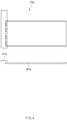
- FIG. 4 is a plan and front view illustrating one side of a support part according to the first embodiment of the present invention
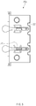
- FIG. 5 is a plan view of a fixed module according to the first embodiment of the present invention.
- a jig device has a structure for inspecting a secondary battery having a one-way structure in which the lead is disposed on only one side.
- a side from which the lead protrudes is disposed to come into contact with a fixed module 20a.
- the support part 40a comprises a mount 41a mounted on an edge portion of a seating hole 11 and a support 42a coupled to the mount 41a with a stepped portion (a height difference) therebetween to support the secondary battery.
- the mount 41a and the support 42a may have various shapes and sizes according to a shape of the secondary battery or required conditions of the inspection apparatus.
- a measuring device 70 for measuring a size of a lead partially protruding from the secondary battery when the secondary battery is seated adjacent to the fixed module 20a may be mounted (see FIG. 3 ).
- holes 22 for measuring a stepped portion (for example, a deviation in width and length due to mass-production) of the secondary battery may be additionally formed.
- the holes 22 may be disposed at predetermined intervals.
- a method for measuring a degree of the deviation or a method for measuring the deviation by displaying scales on the holes may be applied according to the number of holes 22.
- a clamp for fixing or separating the support part 40a may be additionally mounted on the fixed module 20a to easily realize the connection of the support part 40a.
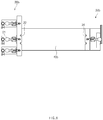
- FIG. 6 is a plan view of a jig device according to a second embodiment of the present invention
- FIG. 7 is a plan and front view of a support part according to the second embodiment of the present invention
- FIG. 8 is a plan view of a fixed module and a gliding module according to the second embodiment of the present invention.
- a jig device has a structure for inspecting a secondary battery having a two-way structure in which the lead is disposed on each of both sides.
- a side from which one lead protrudes is disposed to come into contact with a fixed module 20b.
- the support part 40b comprises a mount 41b mounted on an edge portion of a seating hole 11 and a support 42b coupled to the mount 41b with a stepped portion therebetween to support the secondary battery.
- the mount 41b and the support 42b may have various shapes and sizes according to a shape of the secondary battery or required conditions of the inspection apparatus.
- the support part 40b has shape with a width that is narrower than that of each of the secondary battery and the seating hole.
- the support part 40b may have a shape of which a portion connected to the fixed module 20b and the first gliding module 30b has a width narrower than that of a central portion thereof.
- measuring devices 70 and 71 for measuring a size of a lead partially protruding from the secondary battery when the secondary battery is seated adjacent to the fixed module 20b may be respectively mounted on both sides (see FIG. 6 ).
- holes 22 and 34 for measuring a stepped portion of the secondary battery may be formed in both sides.
- the holes 22 and 34 for measuring the stepped portion may be formed in the fixed module 20b and the first gliding module 30b and also formed in the mount 41b of the support part 40b.
- clamps 21 for fixing or separating the support part 40b may be disposed on both sides, respectively.
- the measuring devices 70 and 71 may be selectively mounted on any one place or all both sides as necessary to measure the size of lead the partially protruding from the secondary battery.
- the first gliding module 30 and the support part 40 are individually separable, secondary batteries having various sizes may be disposed on a jig base 10, and the first gliding module 30 and the support part 40 may be replaced with the first gliding module 30 and the support part 40, which match a size of a replaced secondary battery. That is, for example, only a portion of the first gliding module 30 and the support part 40 may be replaced in a state in which the jig base 10 and the fixed module 20 are left in place to fix the secondary batteries having the various sizes.
- masking blocks 50a, 50b, and 50c may be detachably mounted on a portion coming into contact with a sealing part of the secondary battery.
- a pressure by which the sealing part of the secondary battery is deformed may be prevented from being applied to the sealing part.
- the masking blocks 50a, 50b, and 50c may absorb an impact like sponge to transmit force. Also, each of the masking blocks 50a, 50b, and 50c may be elastically deformed to a shape that is depressed from the portion coming into contact with the sealing part by the pressure. Thus, the masking blocks 50a, 50b, and 50c may come into contact with each other in a vertical direction of the sealing part at the portion of the sealing part, which is depressed by the pressure to more effectively suppress the shaking and movement of the sealing part.
- the fixed module may also be replaced, and the second gliding module 60 that is glided in a direction crossing the first gliding module 30 may be additionally provided to support the secondary battery in various directions.
- each of the first gliding module 30 and the second gliding module 60 is glided by two or more hand drive bolts 31, 32, 33, 61, 62, and 63, the user may easily horizontally align the first gliding module 30 and the second gliding module 60.
- the support part 40 prevents the secondary battery from drooping and has the shape that is partially reduced in width, an area through which ultrasonic waves pass through the seating hole via the sealing part may increase.
- measuring devices 70 and 71 for measuring dimensions of the secondary battery may be added to measure the size of the lead in addition to the quality inspection using the ultrasonic waves.
- the support part 40 may be mounted on the fixed module and the first gliding module through the clamp 31 and thus be easily separated.
Landscapes
- Engineering & Computer Science (AREA)
- Manufacturing & Machinery (AREA)
- Chemical & Material Sciences (AREA)
- Chemical Kinetics & Catalysis (AREA)
- Electrochemistry (AREA)
- General Chemical & Material Sciences (AREA)
- Physics & Mathematics (AREA)
- General Physics & Mathematics (AREA)
- Optics & Photonics (AREA)
- Mechanical Engineering (AREA)
- Battery Mounting, Suspending (AREA)
Claims (10)
- Dispositif de gabarit pour inspecter la qualité d'une batterie secondaire, qui fixe la batterie secondaire et inspecte la qualité de la batterie secondaire en utilisant des ondes ultrasonores, le dispositif de gabarit comprenant :un dispositif d'inspection ultrasonore ;une base de gabarit (10) ayant une forme de plaque et un orifice d'assise (11) ;une partie de paroi (15) en saillie vers le haut le long d'une circonférence de la base de gabarit ;un module fixe (20) monté sur la base de gabarit au niveau d'un côté de l'orifice d'assise ;un premier module glissant (30) monté sur la base de gabarit au niveau d'un côté opposé au module fixe et capable de glisser vers le module fixe ;un second module glissant (60) qui peut glisser dans une direction perpendiculaire au premier module glissant, monté sur une position quelconque de la partie de paroi ; etune partie de support (40) s'étendant en travers de l'orifice d'assise, la partie de support ayant une première extrémité raccordée au module fixe et une seconde extrémité raccordée au premier module glissant et sur laquelle est placée la batterie secondaire,dans lequel un bloc de masquage (50a) est monté sur une ou plusieurs portions du module fixe (20) et du premier module glissant (30), qui vient en contact avec un bord de la batterie secondaire lorsqu'elle est placée sur la partie de support, et lorsque le bloc de masquage est au contact du bord de la batterie secondaire, la batterie secondaire est fixe,dans lequel un autre bloc de masquage (50b) est monté de manière détachable sur une portion du second module glissant (60), qui vient en contact avec le bord de la batterie secondaire,dans lequel un bloc de masquage supplémentaire (50c) est monté de manière détachable sur la partie de paroi (15) opposée au second module glissant (60) de sorte que, lorsque la batterie secondaire est déplacée par le second module glissant, le bloc de masquage supplémentaire vient en contact avec la batterie secondaire,dans lequel le bloc de masquage (50a), l'autre bloc de masquage (50b) et le bloc de masquage supplémentaire (50c) sont constitués d'un matériau ayant une élasticité pour empêcher la partie d'étanchéité de la batterie secondaire d'être pressée pour être déformée,dans lequel le premier module glissant peut être détaché de la base de gabarit, etdans lequel la partie de support (40) a une taille à laquelle l'orifice d'assise (11) entier n'est pas couvert et peut être séparé du module fixe et du premier module glissant.
- Dispositif de gabarit selon la revendication 1, dans lequel le module fixe peut être détaché de la base de gabarit.
- Dispositif de gabarit selon la revendication 1, dans lequel chacun du premier module glissant (30) et du second module glissant (60) est ajusté selon un sens de rotation d'un boulon manuel (31, 32, 33, 61, 62, 63), le boulon manuel étant couplé par vissage pour passer à travers la partie de paroi.
- Dispositif de gabarit selon la revendication 3, dans lequel chaque boulon manuel (31, 32, 33, 61, 62, 63) est prévu en une pluralité de sorte qu'au moins deux boulons manuels ou plus soient espacés l'un de l'autre et soient montés sur chacun du premier module glissant et du second module glissant.
- Dispositif de gabarit selon la revendication 1, dans lequel le bloc de masquage est constitué d'un matériau de silicium.
- Dispositif de gabarit selon l'une quelconque des revendications 1 et 2, dans lequel la partie de support (40) a une largeur qui est inférieure à une largeur de chacun(e) de la batterie secondaire et de l'orifice d'assise.
- Dispositif de gabarit selon la revendication 6, dans lequel la partie de support (40) a une forme dont des portions raccordées au module fixe et au premier module glissant ont une largeur qui est inférieure à celle d'une portion centrale de la partie de support.
- Dispositif de gabarit selon l'une quelconque des revendications 1 et 2, comprenant en outre un dispositif de mesure monté sur le module fixe pour mesurer une taille d'un fil de connexion partiellement saillant depuis la batterie secondaire lorsque la batterie secondaire est assise adjacente au module fixe.
- Dispositif de gabarit selon la revendication 8, comprenant en outre un autre dispositif de mesure monté sur le premier module glissant pour mesurer la taille de l'autre fil de connexion partiellement saillant depuis la batterie secondaire lorsque la batterie secondaire est assise adjacente au premier module glissant.
- Dispositif de gabarit selon l'une quelconque des revendications 1 et 2, dans lequel une pince est montée sur chacun du module fixe et du premier module glissant, et la pince de chacun du module fixe et du premier module glissant peut être raccordée à la partie de support.
Applications Claiming Priority (2)
| Application Number | Priority Date | Filing Date | Title |
|---|---|---|---|
| KR1020170082713A KR102132754B1 (ko) | 2017-06-29 | 2017-06-29 | 이차전지 품질검사용 지그장치 |
| PCT/KR2018/003624 WO2019004567A1 (fr) | 2017-06-29 | 2018-03-27 | Dispositif de gabarit d'inspection de qualité d'accumulateur |
Publications (3)
| Publication Number | Publication Date |
|---|---|
| EP3506414A1 EP3506414A1 (fr) | 2019-07-03 |
| EP3506414A4 EP3506414A4 (fr) | 2019-08-07 |
| EP3506414B1 true EP3506414B1 (fr) | 2020-07-22 |
Family
ID=64741659
Family Applications (1)
| Application Number | Title | Priority Date | Filing Date |
|---|---|---|---|
| EP18825160.7A Active EP3506414B1 (fr) | 2017-06-29 | 2018-03-27 | Dispositif de gabarit d'inspection de qualité d'accumulateur |
Country Status (5)
| Country | Link |
|---|---|
| US (1) | US10957943B2 (fr) |
| EP (1) | EP3506414B1 (fr) |
| KR (1) | KR102132754B1 (fr) |
| CN (1) | CN109845022B (fr) |
| WO (1) | WO2019004567A1 (fr) |
Families Citing this family (12)
| Publication number | Priority date | Publication date | Assignee | Title |
|---|---|---|---|---|
| CN110193665A (zh) * | 2019-06-19 | 2019-09-03 | 广东风华新能源股份有限公司 | 一种锂电池的激光焊接夹具 |
| CN112247437A (zh) * | 2020-01-20 | 2021-01-22 | 蜂巢能源科技有限公司 | 用于电芯的焊接的夹具以及焊接电芯的方法 |
| CN111693742A (zh) * | 2020-07-17 | 2020-09-22 | 深圳市新威尔电子有限公司 | 圆柱电池大电流测试夹具 |
| KR20230076705A (ko) | 2021-11-24 | 2023-05-31 | 주식회사 원익피앤이 | 이차전지 케이스의 실링 품질 제어 장치 및 방법 |
| KR102779141B1 (ko) * | 2022-04-27 | 2025-03-12 | 한화모멘텀 주식회사 | 이차전지 손상 검사장치 및 이를 이용한 이차전지의 손상 검사방법 |
| KR20240013367A (ko) | 2022-07-22 | 2024-01-30 | 주식회사 엘지에너지솔루션 | 원통형 이차전지 고정 지그 및 안전성 평가 방법 |
| KR102837024B1 (ko) * | 2022-11-30 | 2025-07-21 | 호남대학교 산학협력단 | 폐배터리 진단용 지그 |
| KR20240107829A (ko) | 2022-12-30 | 2024-07-09 | 지텍 주식회사 | 안전케이스를 구비한 배터리셀 간이검사지그 모듈 |
| KR102580372B1 (ko) * | 2023-03-10 | 2023-09-19 | 주식회사 제이디 | 레이저 가열용 파우치형 이차전지 씰링면 검사 지그 및 장치 |
| KR102547866B1 (ko) * | 2023-03-10 | 2023-06-26 | 주식회사 제이디 | 접촉 가열용 파우치형 이차전지 씰링면 검사 지그 및 장치 |
| CN116551234B (zh) * | 2023-05-22 | 2024-07-23 | 深圳市汇鼎智能制造技术有限公司 | 一种电芯模组焊接机构、电芯模组焊接流水线及焊接方法 |
| CN116718317B (zh) * | 2023-08-09 | 2024-02-20 | 江苏常丰精密科技有限公司 | 一种动力电池壳体检漏装置 |
Family Cites Families (21)
| Publication number | Priority date | Publication date | Assignee | Title |
|---|---|---|---|---|
| GB1193501A (en) | 1967-02-02 | 1970-06-03 | Watson W & Sons Ltd | Improvements in or relating to Positioning Apparatus |
| JP4666712B2 (ja) * | 2000-02-22 | 2011-04-06 | パナソニック株式会社 | 電池の短絡検査方法 |
| KR101031538B1 (ko) | 2009-04-13 | 2011-04-27 | 주식회사 피앤이솔루션 | 리튬폴리머 전지의 충,방전 지그 |
| JP5566719B2 (ja) | 2010-02-15 | 2014-08-06 | 株式会社東芝 | 二次電池装置 |
| US8680869B2 (en) * | 2010-02-16 | 2014-03-25 | Blackberry Limited | AC charging contact mechanism |
| EP2557627B1 (fr) | 2010-04-07 | 2016-04-06 | Eig Ltd. | Module de batterie rechargeable |
| CN202444010U (zh) | 2011-12-22 | 2012-09-19 | 四川大学 | 一种手机外接充电器电池盒 |
| KR101534515B1 (ko) | 2013-05-14 | 2015-07-07 | (주)에이치엔티 | 투웨이 배터리 지그 |
| JP6069109B2 (ja) * | 2013-06-12 | 2017-01-25 | 浜松ホトニクス株式会社 | 試料保持部材の挿抜機構及び画像取得装置 |
| KR101551534B1 (ko) * | 2013-09-30 | 2015-09-08 | 주식회사 엘지화학 | 테스트 지그 |
| KR101798688B1 (ko) * | 2013-10-21 | 2017-11-16 | 주식회사 엘지화학 | 전지셀의 기능 검사 지그 |
| KR101772729B1 (ko) * | 2013-10-30 | 2017-08-29 | 주식회사 엘지화학 | 지그장치 및 그를 이용한 가공방법 |
| KR101713182B1 (ko) * | 2013-10-31 | 2017-03-07 | 주식회사 엘지화학 | 이차 전지 고정 지그 및 이를 포함하는 이차 전지 충방전 장치 |
| JP2015153731A (ja) | 2014-02-19 | 2015-08-24 | 株式会社京浜理化工業 | 試験用電池セル |
| CN104049115B (zh) | 2014-06-16 | 2017-02-01 | 深圳市瑞能实业股份有限公司 | 聚合物软包电池检测夹具 |
| KR102091826B1 (ko) * | 2014-06-17 | 2020-03-20 | 에스케이이노베이션 주식회사 | 배터리 셀 수납용 트레이 |
| KR20160015751A (ko) * | 2014-07-31 | 2016-02-15 | 에스케이이노베이션 주식회사 | 배터리 셀 치수 고정을 위한 배터리모듈 구조, 그리고 이를 이용한 배터리 셀의 병렬 연결 구조 |
| KR101790639B1 (ko) * | 2014-12-15 | 2017-10-26 | 주식회사 엘지화학 | 이차전지의 충방전 또는 테스트용 이차전지 고정 지그 |
| KR101717838B1 (ko) | 2015-04-07 | 2017-03-17 | 이동석 | 배터리 불량 검사 장치 |
| KR102039526B1 (ko) | 2016-07-12 | 2019-11-01 | 주식회사 엘지화학 | 파우치형 이차전지의 밀봉성 검사 장치 및 검사 방법 |
| US10629966B2 (en) * | 2016-11-02 | 2020-04-21 | Feasible, Inc. | Modular, adaptable holders for sensors and battery cells for physical analysis |
-
2017
- 2017-06-29 KR KR1020170082713A patent/KR102132754B1/ko active Active
-
2018
- 2018-03-27 US US16/337,313 patent/US10957943B2/en active Active
- 2018-03-27 WO PCT/KR2018/003624 patent/WO2019004567A1/fr not_active Ceased
- 2018-03-27 EP EP18825160.7A patent/EP3506414B1/fr active Active
- 2018-03-27 CN CN201880003868.3A patent/CN109845022B/zh active Active
Non-Patent Citations (1)
| Title |
|---|
| None * |
Also Published As
| Publication number | Publication date |
|---|---|
| KR20190002180A (ko) | 2019-01-08 |
| WO2019004567A1 (fr) | 2019-01-03 |
| CN109845022A (zh) | 2019-06-04 |
| US10957943B2 (en) | 2021-03-23 |
| CN109845022B (zh) | 2021-11-26 |
| EP3506414A1 (fr) | 2019-07-03 |
| KR102132754B1 (ko) | 2020-07-13 |
| EP3506414A4 (fr) | 2019-08-07 |
| US20200036054A1 (en) | 2020-01-30 |
Similar Documents
| Publication | Publication Date | Title |
|---|---|---|
| EP3506414B1 (fr) | Dispositif de gabarit d'inspection de qualité d'accumulateur | |
| US11522258B2 (en) | Electrolyte removing device, apparatus and method for manufacturing secondary battery comprising the same, and secondary battery | |
| US10741870B2 (en) | Battery cell degassing apparatus | |
| KR102291536B1 (ko) | 배터리 팩 검사 장치 및 방법 | |
| KR20180087040A (ko) | 이차 전지 평가 장치 | |
| EP3907809B1 (fr) | Appareil de test de court-circuit à pression pour détecter un élément de batterie secondaire de type poche de basse tension défectueux | |
| KR101451731B1 (ko) | 신규한 구조의 전지셀 충방전 장치 | |
| EP3920283A4 (fr) | Matériau actif d'électrode positive et son procédé de préparation, plaque d'électrode positive, batterie secondaire au lithium-ion et module de batterie la comprenant, bloc-batterie et dispositif | |
| WO2015141631A1 (fr) | Dispositif de mise sous pression pour cellules de batterie | |
| KR102933142B1 (ko) | 배터리 스웰링 검사 장치 및 방법 | |
| KR20200056531A (ko) | 이차 전지의 탑 캡 어셈블리 조립장치 및 그를 이용한 조립방법 | |
| KR101839566B1 (ko) | 전지팩의 시트 부착 장치 | |
| US10707460B2 (en) | Manufacturing method of assembled battery | |
| EP3993133A1 (fr) | Appareil de détection d'électrolyte et équipement de transfert de batterie secondaire le comprenant | |
| SE452528B (sv) | Anordning vid ett elektrokemiskt ackumulatorbatteri for tetande genomforing av ett skruvforband for elektrisk forbindelse genom en oppning i en cellvegg | |
| KR101630214B1 (ko) | 전지의 기능검사용 클램핑 장치 | |
| CN114994544A (zh) | 一种锂离子电池制造安全测试装置 | |
| KR101456424B1 (ko) | 신규한 구조의 두께 검사 장치 | |
| CN109964352A (zh) | 用于制造电池组的设备 | |
| KR20150098833A (ko) | 용접지그 | |
| EP4353402A1 (fr) | Appareil et procédé de test de l'état soudé d'une batterie secondaire cylindrique | |
| CN210221363U (zh) | 一种锂电池壳体封口板嵌合力测量设备 | |
| KR20250026675A (ko) | 전지셀 충방전 지그 및 이를 이용한 전지셀 충방전 방법 | |
| KR20080064918A (ko) | 온도 및 전압 측정장치 | |
| JP2021530682A (ja) | X線を用いた電池測定装置 |
Legal Events
| Date | Code | Title | Description |
|---|---|---|---|
| STAA | Information on the status of an ep patent application or granted ep patent |
Free format text: STATUS: THE INTERNATIONAL PUBLICATION HAS BEEN MADE |
|
| PUAI | Public reference made under article 153(3) epc to a published international application that has entered the european phase |
Free format text: ORIGINAL CODE: 0009012 |
|
| STAA | Information on the status of an ep patent application or granted ep patent |
Free format text: STATUS: REQUEST FOR EXAMINATION WAS MADE |
|
| 17P | Request for examination filed |
Effective date: 20190328 |
|
| AK | Designated contracting states |
Kind code of ref document: A1 Designated state(s): AL AT BE BG CH CY CZ DE DK EE ES FI FR GB GR HR HU IE IS IT LI LT LU LV MC MK MT NL NO PL PT RO RS SE SI SK SM TR |
|
| AX | Request for extension of the european patent |
Extension state: BA ME |
|
| A4 | Supplementary search report drawn up and despatched |
Effective date: 20190709 |
|
| RIC1 | Information provided on ipc code assigned before grant |
Ipc: H01M 10/42 20060101AFI20190703BHEP |
|
| GRAP | Despatch of communication of intention to grant a patent |
Free format text: ORIGINAL CODE: EPIDOSNIGR1 |
|
| STAA | Information on the status of an ep patent application or granted ep patent |
Free format text: STATUS: GRANT OF PATENT IS INTENDED |
|
| DAV | Request for validation of the european patent (deleted) | ||
| DAX | Request for extension of the european patent (deleted) | ||
| INTG | Intention to grant announced |
Effective date: 20200309 |
|
| GRAS | Grant fee paid |
Free format text: ORIGINAL CODE: EPIDOSNIGR3 |
|
| GRAA | (expected) grant |
Free format text: ORIGINAL CODE: 0009210 |
|
| STAA | Information on the status of an ep patent application or granted ep patent |
Free format text: STATUS: THE PATENT HAS BEEN GRANTED |
|
| AK | Designated contracting states |
Kind code of ref document: B1 Designated state(s): AL AT BE BG CH CY CZ DE DK EE ES FI FR GB GR HR HU IE IS IT LI LT LU LV MC MK MT NL NO PL PT RO RS SE SI SK SM TR |
|
| REG | Reference to a national code |
Ref country code: GB Ref legal event code: FG4D |
|
| REG | Reference to a national code |
Ref country code: CH Ref legal event code: EP |
|
| REG | Reference to a national code |
Ref country code: DE Ref legal event code: R096 Ref document number: 602018006290 Country of ref document: DE |
|
| REG | Reference to a national code |
Ref country code: AT Ref legal event code: REF Ref document number: 1294252 Country of ref document: AT Kind code of ref document: T Effective date: 20200815 |
|
| REG | Reference to a national code |
Ref country code: IE Ref legal event code: FG4D |
|
| REG | Reference to a national code |
Ref country code: LT Ref legal event code: MG4D |
|
| REG | Reference to a national code |
Ref country code: AT Ref legal event code: MK05 Ref document number: 1294252 Country of ref document: AT Kind code of ref document: T Effective date: 20200722 |
|
| PG25 | Lapsed in a contracting state [announced via postgrant information from national office to epo] |
Ref country code: GR Free format text: LAPSE BECAUSE OF FAILURE TO SUBMIT A TRANSLATION OF THE DESCRIPTION OR TO PAY THE FEE WITHIN THE PRESCRIBED TIME-LIMIT Effective date: 20201023 Ref country code: NO Free format text: LAPSE BECAUSE OF FAILURE TO SUBMIT A TRANSLATION OF THE DESCRIPTION OR TO PAY THE FEE WITHIN THE PRESCRIBED TIME-LIMIT Effective date: 20201022 Ref country code: FI Free format text: LAPSE BECAUSE OF FAILURE TO SUBMIT A TRANSLATION OF THE DESCRIPTION OR TO PAY THE FEE WITHIN THE PRESCRIBED TIME-LIMIT Effective date: 20200722 Ref country code: LT Free format text: LAPSE BECAUSE OF FAILURE TO SUBMIT A TRANSLATION OF THE DESCRIPTION OR TO PAY THE FEE WITHIN THE PRESCRIBED TIME-LIMIT Effective date: 20200722 Ref country code: PT Free format text: LAPSE BECAUSE OF FAILURE TO SUBMIT A TRANSLATION OF THE DESCRIPTION OR TO PAY THE FEE WITHIN THE PRESCRIBED TIME-LIMIT Effective date: 20201123 Ref country code: HR Free format text: LAPSE BECAUSE OF FAILURE TO SUBMIT A TRANSLATION OF THE DESCRIPTION OR TO PAY THE FEE WITHIN THE PRESCRIBED TIME-LIMIT Effective date: 20200722 Ref country code: AT Free format text: LAPSE BECAUSE OF FAILURE TO SUBMIT A TRANSLATION OF THE DESCRIPTION OR TO PAY THE FEE WITHIN THE PRESCRIBED TIME-LIMIT Effective date: 20200722 Ref country code: BG Free format text: LAPSE BECAUSE OF FAILURE TO SUBMIT A TRANSLATION OF THE DESCRIPTION OR TO PAY THE FEE WITHIN THE PRESCRIBED TIME-LIMIT Effective date: 20201022 Ref country code: SE Free format text: LAPSE BECAUSE OF FAILURE TO SUBMIT A TRANSLATION OF THE DESCRIPTION OR TO PAY THE FEE WITHIN THE PRESCRIBED TIME-LIMIT Effective date: 20200722 Ref country code: ES Free format text: LAPSE BECAUSE OF FAILURE TO SUBMIT A TRANSLATION OF THE DESCRIPTION OR TO PAY THE FEE WITHIN THE PRESCRIBED TIME-LIMIT Effective date: 20200722 |
|
| PG25 | Lapsed in a contracting state [announced via postgrant information from national office to epo] |
Ref country code: PL Free format text: LAPSE BECAUSE OF FAILURE TO SUBMIT A TRANSLATION OF THE DESCRIPTION OR TO PAY THE FEE WITHIN THE PRESCRIBED TIME-LIMIT Effective date: 20200722 Ref country code: RS Free format text: LAPSE BECAUSE OF FAILURE TO SUBMIT A TRANSLATION OF THE DESCRIPTION OR TO PAY THE FEE WITHIN THE PRESCRIBED TIME-LIMIT Effective date: 20200722 Ref country code: LV Free format text: LAPSE BECAUSE OF FAILURE TO SUBMIT A TRANSLATION OF THE DESCRIPTION OR TO PAY THE FEE WITHIN THE PRESCRIBED TIME-LIMIT Effective date: 20200722 Ref country code: IS Free format text: LAPSE BECAUSE OF FAILURE TO SUBMIT A TRANSLATION OF THE DESCRIPTION OR TO PAY THE FEE WITHIN THE PRESCRIBED TIME-LIMIT Effective date: 20201122 |
|
| PG25 | Lapsed in a contracting state [announced via postgrant information from national office to epo] |
Ref country code: NL Free format text: LAPSE BECAUSE OF FAILURE TO SUBMIT A TRANSLATION OF THE DESCRIPTION OR TO PAY THE FEE WITHIN THE PRESCRIBED TIME-LIMIT Effective date: 20200722 |
|
| REG | Reference to a national code |
Ref country code: DE Ref legal event code: R097 Ref document number: 602018006290 Country of ref document: DE |
|
| PG25 | Lapsed in a contracting state [announced via postgrant information from national office to epo] |
Ref country code: SM Free format text: LAPSE BECAUSE OF FAILURE TO SUBMIT A TRANSLATION OF THE DESCRIPTION OR TO PAY THE FEE WITHIN THE PRESCRIBED TIME-LIMIT Effective date: 20200722 Ref country code: IT Free format text: LAPSE BECAUSE OF FAILURE TO SUBMIT A TRANSLATION OF THE DESCRIPTION OR TO PAY THE FEE WITHIN THE PRESCRIBED TIME-LIMIT Effective date: 20200722 Ref country code: EE Free format text: LAPSE BECAUSE OF FAILURE TO SUBMIT A TRANSLATION OF THE DESCRIPTION OR TO PAY THE FEE WITHIN THE PRESCRIBED TIME-LIMIT Effective date: 20200722 Ref country code: RO Free format text: LAPSE BECAUSE OF FAILURE TO SUBMIT A TRANSLATION OF THE DESCRIPTION OR TO PAY THE FEE WITHIN THE PRESCRIBED TIME-LIMIT Effective date: 20200722 Ref country code: DK Free format text: LAPSE BECAUSE OF FAILURE TO SUBMIT A TRANSLATION OF THE DESCRIPTION OR TO PAY THE FEE WITHIN THE PRESCRIBED TIME-LIMIT Effective date: 20200722 Ref country code: CZ Free format text: LAPSE BECAUSE OF FAILURE TO SUBMIT A TRANSLATION OF THE DESCRIPTION OR TO PAY THE FEE WITHIN THE PRESCRIBED TIME-LIMIT Effective date: 20200722 |
|
| PLBE | No opposition filed within time limit |
Free format text: ORIGINAL CODE: 0009261 |
|
| STAA | Information on the status of an ep patent application or granted ep patent |
Free format text: STATUS: NO OPPOSITION FILED WITHIN TIME LIMIT |
|
| PG25 | Lapsed in a contracting state [announced via postgrant information from national office to epo] |
Ref country code: AL Free format text: LAPSE BECAUSE OF FAILURE TO SUBMIT A TRANSLATION OF THE DESCRIPTION OR TO PAY THE FEE WITHIN THE PRESCRIBED TIME-LIMIT Effective date: 20200722 |
|
| 26N | No opposition filed |
Effective date: 20210423 |
|
| PG25 | Lapsed in a contracting state [announced via postgrant information from national office to epo] |
Ref country code: SK Free format text: LAPSE BECAUSE OF FAILURE TO SUBMIT A TRANSLATION OF THE DESCRIPTION OR TO PAY THE FEE WITHIN THE PRESCRIBED TIME-LIMIT Effective date: 20200722 |
|
| PG25 | Lapsed in a contracting state [announced via postgrant information from national office to epo] |
Ref country code: SI Free format text: LAPSE BECAUSE OF FAILURE TO SUBMIT A TRANSLATION OF THE DESCRIPTION OR TO PAY THE FEE WITHIN THE PRESCRIBED TIME-LIMIT Effective date: 20200722 |
|
| REG | Reference to a national code |
Ref country code: NL Ref legal event code: MP Effective date: 20200722 |
|
| PG25 | Lapsed in a contracting state [announced via postgrant information from national office to epo] |
Ref country code: MC Free format text: LAPSE BECAUSE OF FAILURE TO SUBMIT A TRANSLATION OF THE DESCRIPTION OR TO PAY THE FEE WITHIN THE PRESCRIBED TIME-LIMIT Effective date: 20200722 |
|
| REG | Reference to a national code |
Ref country code: CH Ref legal event code: PL |
|
| REG | Reference to a national code |
Ref country code: BE Ref legal event code: MM Effective date: 20210331 |
|
| PG25 | Lapsed in a contracting state [announced via postgrant information from national office to epo] |
Ref country code: IE Free format text: LAPSE BECAUSE OF NON-PAYMENT OF DUE FEES Effective date: 20210327 Ref country code: LU Free format text: LAPSE BECAUSE OF NON-PAYMENT OF DUE FEES Effective date: 20210327 Ref country code: LI Free format text: LAPSE BECAUSE OF NON-PAYMENT OF DUE FEES Effective date: 20210331 Ref country code: CH Free format text: LAPSE BECAUSE OF NON-PAYMENT OF DUE FEES Effective date: 20210331 |
|
| PG25 | Lapsed in a contracting state [announced via postgrant information from national office to epo] |
Ref country code: BE Free format text: LAPSE BECAUSE OF NON-PAYMENT OF DUE FEES Effective date: 20210331 |
|
| REG | Reference to a national code |
Ref country code: DE Ref legal event code: R081 Ref document number: 602018006290 Country of ref document: DE Owner name: LG ENERGY SOLUTION, LTD., KR Free format text: FORMER OWNER: LG CHEM. LTD., SEOUL, KR |
|
| P01 | Opt-out of the competence of the unified patent court (upc) registered |
Effective date: 20230512 |
|
| PG25 | Lapsed in a contracting state [announced via postgrant information from national office to epo] |
Ref country code: CY Free format text: LAPSE BECAUSE OF FAILURE TO SUBMIT A TRANSLATION OF THE DESCRIPTION OR TO PAY THE FEE WITHIN THE PRESCRIBED TIME-LIMIT Effective date: 20200722 |
|
| PG25 | Lapsed in a contracting state [announced via postgrant information from national office to epo] |
Ref country code: HU Free format text: LAPSE BECAUSE OF FAILURE TO SUBMIT A TRANSLATION OF THE DESCRIPTION OR TO PAY THE FEE WITHIN THE PRESCRIBED TIME-LIMIT; INVALID AB INITIO Effective date: 20180327 |
|
| REG | Reference to a national code |
Ref country code: GB Ref legal event code: 732E Free format text: REGISTERED BETWEEN 20230824 AND 20230831 |
|
| PG25 | Lapsed in a contracting state [announced via postgrant information from national office to epo] |
Ref country code: MK Free format text: LAPSE BECAUSE OF FAILURE TO SUBMIT A TRANSLATION OF THE DESCRIPTION OR TO PAY THE FEE WITHIN THE PRESCRIBED TIME-LIMIT Effective date: 20200722 |
|
| PG25 | Lapsed in a contracting state [announced via postgrant information from national office to epo] |
Ref country code: MT Free format text: LAPSE BECAUSE OF FAILURE TO SUBMIT A TRANSLATION OF THE DESCRIPTION OR TO PAY THE FEE WITHIN THE PRESCRIBED TIME-LIMIT Effective date: 20200722 |
|
| PG25 | Lapsed in a contracting state [announced via postgrant information from national office to epo] |
Ref country code: TR Free format text: LAPSE BECAUSE OF FAILURE TO SUBMIT A TRANSLATION OF THE DESCRIPTION OR TO PAY THE FEE WITHIN THE PRESCRIBED TIME-LIMIT Effective date: 20200722 |
|
| PGFP | Annual fee paid to national office [announced via postgrant information from national office to epo] |
Ref country code: GB Payment date: 20260224 Year of fee payment: 9 |
|
| PGFP | Annual fee paid to national office [announced via postgrant information from national office to epo] |
Ref country code: DE Payment date: 20260220 Year of fee payment: 9 |
|
| PGFP | Annual fee paid to national office [announced via postgrant information from national office to epo] |
Ref country code: FR Payment date: 20260224 Year of fee payment: 9 |