EP3506431A2 - Connecteur de conduite, ensemble de conduites électrique ainsi que procédé de fabrication d'une connexion électrique - Google Patents
Connecteur de conduite, ensemble de conduites électrique ainsi que procédé de fabrication d'une connexion électrique Download PDFInfo
- Publication number
- EP3506431A2 EP3506431A2 EP18214329.7A EP18214329A EP3506431A2 EP 3506431 A2 EP3506431 A2 EP 3506431A2 EP 18214329 A EP18214329 A EP 18214329A EP 3506431 A2 EP3506431 A2 EP 3506431A2
- Authority
- EP
- European Patent Office
- Prior art keywords
- receiving sleeve
- lines
- line
- electrical
- connector
- Prior art date
- Legal status (The legal status is an assumption and is not a legal conclusion. Google has not performed a legal analysis and makes no representation as to the accuracy of the status listed.)
- Granted
Links
Images


Classifications
-
- H—ELECTRICITY
- H02—GENERATION; CONVERSION OR DISTRIBUTION OF ELECTRIC POWER
- H02G—INSTALLATION OF ELECTRIC CABLES OR LINES, OR OF COMBINED OPTICAL AND ELECTRIC CABLES OR LINES
- H02G15/00—Cable fittings
- H02G15/08—Cable junctions
- H02G15/18—Cable junctions protected by sleeves, e.g. for communication cable
-
- H—ELECTRICITY
- H01—ELECTRIC ELEMENTS
- H01R—ELECTRICALLY-CONDUCTIVE CONNECTIONS; STRUCTURAL ASSOCIATIONS OF A PLURALITY OF MUTUALLY-INSULATED ELECTRICAL CONNECTING ELEMENTS; COUPLING DEVICES; CURRENT COLLECTORS
- H01R11/00—Individual connecting elements providing two or more spaced connecting locations for conductive members which are, or may be, thereby interconnected, e.g. end pieces for wires or cables supported by the wire or cable and having means for facilitating electrical connection to some other wire, terminal, or conductive member, blocks of binding posts
- H01R11/11—End pieces or tapping pieces for wires, supported by the wire and for facilitating electrical connection to some other wire, terminal or conductive member
- H01R11/12—End pieces terminating in an eye, hook, or fork
-
- H—ELECTRICITY
- H01—ELECTRIC ELEMENTS
- H01R—ELECTRICALLY-CONDUCTIVE CONNECTIONS; STRUCTURAL ASSOCIATIONS OF A PLURALITY OF MUTUALLY-INSULATED ELECTRICAL CONNECTING ELEMENTS; COUPLING DEVICES; CURRENT COLLECTORS
- H01R4/00—Electrically-conductive connections between two or more conductive members in direct contact, i.e. touching one another; Means for effecting or maintaining such contact; Electrically-conductive connections having two or more spaced connecting locations for conductors and using contact members penetrating insulation
- H01R4/02—Soldered or welded connections
- H01R4/023—Soldered or welded connections between cables or wires and terminals
-
- H—ELECTRICITY
- H01—ELECTRIC ELEMENTS
- H01R—ELECTRICALLY-CONDUCTIVE CONNECTIONS; STRUCTURAL ASSOCIATIONS OF A PLURALITY OF MUTUALLY-INSULATED ELECTRICAL CONNECTING ELEMENTS; COUPLING DEVICES; CURRENT COLLECTORS
- H01R4/00—Electrically-conductive connections between two or more conductive members in direct contact, i.e. touching one another; Means for effecting or maintaining such contact; Electrically-conductive connections having two or more spaced connecting locations for conductors and using contact members penetrating insulation
- H01R4/10—Electrically-conductive connections between two or more conductive members in direct contact, i.e. touching one another; Means for effecting or maintaining such contact; Electrically-conductive connections having two or more spaced connecting locations for conductors and using contact members penetrating insulation effected solely by twisting, wrapping, bending, crimping, or other permanent deformation
- H01R4/18—Electrically-conductive connections between two or more conductive members in direct contact, i.e. touching one another; Means for effecting or maintaining such contact; Electrically-conductive connections having two or more spaced connecting locations for conductors and using contact members penetrating insulation effected solely by twisting, wrapping, bending, crimping, or other permanent deformation by crimping
- H01R4/183—Electrically-conductive connections between two or more conductive members in direct contact, i.e. touching one another; Means for effecting or maintaining such contact; Electrically-conductive connections having two or more spaced connecting locations for conductors and using contact members penetrating insulation effected solely by twisting, wrapping, bending, crimping, or other permanent deformation by crimping for cylindrical elongated bodies, e.g. cables having circular cross-section
- H01R4/186—Electrically-conductive connections between two or more conductive members in direct contact, i.e. touching one another; Means for effecting or maintaining such contact; Electrically-conductive connections having two or more spaced connecting locations for conductors and using contact members penetrating insulation effected solely by twisting, wrapping, bending, crimping, or other permanent deformation by crimping for cylindrical elongated bodies, e.g. cables having circular cross-section using a body comprising a plurality of cable-accommodating recesses or bores
-
- H—ELECTRICITY
- H01—ELECTRIC ELEMENTS
- H01R—ELECTRICALLY-CONDUCTIVE CONNECTIONS; STRUCTURAL ASSOCIATIONS OF A PLURALITY OF MUTUALLY-INSULATED ELECTRICAL CONNECTING ELEMENTS; COUPLING DEVICES; CURRENT COLLECTORS
- H01R4/00—Electrically-conductive connections between two or more conductive members in direct contact, i.e. touching one another; Means for effecting or maintaining such contact; Electrically-conductive connections having two or more spaced connecting locations for conductors and using contact members penetrating insulation
- H01R4/10—Electrically-conductive connections between two or more conductive members in direct contact, i.e. touching one another; Means for effecting or maintaining such contact; Electrically-conductive connections having two or more spaced connecting locations for conductors and using contact members penetrating insulation effected solely by twisting, wrapping, bending, crimping, or other permanent deformation
- H01R4/18—Electrically-conductive connections between two or more conductive members in direct contact, i.e. touching one another; Means for effecting or maintaining such contact; Electrically-conductive connections having two or more spaced connecting locations for conductors and using contact members penetrating insulation effected solely by twisting, wrapping, bending, crimping, or other permanent deformation by crimping
- H01R4/187—Electrically-conductive connections between two or more conductive members in direct contact, i.e. touching one another; Means for effecting or maintaining such contact; Electrically-conductive connections having two or more spaced connecting locations for conductors and using contact members penetrating insulation effected solely by twisting, wrapping, bending, crimping, or other permanent deformation by crimping combined with soldering or welding
-
- H—ELECTRICITY
- H01—ELECTRIC ELEMENTS
- H01R—ELECTRICALLY-CONDUCTIVE CONNECTIONS; STRUCTURAL ASSOCIATIONS OF A PLURALITY OF MUTUALLY-INSULATED ELECTRICAL CONNECTING ELEMENTS; COUPLING DEVICES; CURRENT COLLECTORS
- H01R4/00—Electrically-conductive connections between two or more conductive members in direct contact, i.e. touching one another; Means for effecting or maintaining such contact; Electrically-conductive connections having two or more spaced connecting locations for conductors and using contact members penetrating insulation
- H01R4/10—Electrically-conductive connections between two or more conductive members in direct contact, i.e. touching one another; Means for effecting or maintaining such contact; Electrically-conductive connections having two or more spaced connecting locations for conductors and using contact members penetrating insulation effected solely by twisting, wrapping, bending, crimping, or other permanent deformation
- H01R4/18—Electrically-conductive connections between two or more conductive members in direct contact, i.e. touching one another; Means for effecting or maintaining such contact; Electrically-conductive connections having two or more spaced connecting locations for conductors and using contact members penetrating insulation effected solely by twisting, wrapping, bending, crimping, or other permanent deformation by crimping
- H01R4/20—Electrically-conductive connections between two or more conductive members in direct contact, i.e. touching one another; Means for effecting or maintaining such contact; Electrically-conductive connections having two or more spaced connecting locations for conductors and using contact members penetrating insulation effected solely by twisting, wrapping, bending, crimping, or other permanent deformation by crimping using a crimping sleeve
-
- H—ELECTRICITY
- H01—ELECTRIC ELEMENTS
- H01R—ELECTRICALLY-CONDUCTIVE CONNECTIONS; STRUCTURAL ASSOCIATIONS OF A PLURALITY OF MUTUALLY-INSULATED ELECTRICAL CONNECTING ELEMENTS; COUPLING DEVICES; CURRENT COLLECTORS
- H01R4/00—Electrically-conductive connections between two or more conductive members in direct contact, i.e. touching one another; Means for effecting or maintaining such contact; Electrically-conductive connections having two or more spaced connecting locations for conductors and using contact members penetrating insulation
- H01R4/58—Electrically-conductive connections between two or more conductive members in direct contact, i.e. touching one another; Means for effecting or maintaining such contact; Electrically-conductive connections having two or more spaced connecting locations for conductors and using contact members penetrating insulation characterised by the form or material of the contacting members
- H01R4/62—Connections between conductors of different materials; Connections between or with aluminium or steel-core aluminium conductors
- H01R4/625—Soldered or welded connections
-
- H—ELECTRICITY
- H01—ELECTRIC ELEMENTS
- H01R—ELECTRICALLY-CONDUCTIVE CONNECTIONS; STRUCTURAL ASSOCIATIONS OF A PLURALITY OF MUTUALLY-INSULATED ELECTRICAL CONNECTING ELEMENTS; COUPLING DEVICES; CURRENT COLLECTORS
- H01R43/00—Apparatus or processes specially adapted for manufacturing, assembling, maintaining, or repairing of line connectors or current collectors or for joining electric conductors
- H01R43/02—Apparatus or processes specially adapted for manufacturing, assembling, maintaining, or repairing of line connectors or current collectors or for joining electric conductors for soldered or welded connections
-
- H—ELECTRICITY
- H01—ELECTRIC ELEMENTS
- H01R—ELECTRICALLY-CONDUCTIVE CONNECTIONS; STRUCTURAL ASSOCIATIONS OF A PLURALITY OF MUTUALLY-INSULATED ELECTRICAL CONNECTING ELEMENTS; COUPLING DEVICES; CURRENT COLLECTORS
- H01R43/00—Apparatus or processes specially adapted for manufacturing, assembling, maintaining, or repairing of line connectors or current collectors or for joining electric conductors
- H01R43/02—Apparatus or processes specially adapted for manufacturing, assembling, maintaining, or repairing of line connectors or current collectors or for joining electric conductors for soldered or welded connections
- H01R43/0249—Apparatus or processes specially adapted for manufacturing, assembling, maintaining, or repairing of line connectors or current collectors or for joining electric conductors for soldered or welded connections for simultaneous welding or soldering of a plurality of wires to contact elements
-
- H—ELECTRICITY
- H01—ELECTRIC ELEMENTS
- H01R—ELECTRICALLY-CONDUCTIVE CONNECTIONS; STRUCTURAL ASSOCIATIONS OF A PLURALITY OF MUTUALLY-INSULATED ELECTRICAL CONNECTING ELEMENTS; COUPLING DEVICES; CURRENT COLLECTORS
- H01R43/00—Apparatus or processes specially adapted for manufacturing, assembling, maintaining, or repairing of line connectors or current collectors or for joining electric conductors
- H01R43/04—Apparatus or processes specially adapted for manufacturing, assembling, maintaining, or repairing of line connectors or current collectors or for joining electric conductors for forming connections by deformation, e.g. crimping tool
- H01R43/048—Crimping apparatus or processes
-
- H—ELECTRICITY
- H02—GENERATION; CONVERSION OR DISTRIBUTION OF ELECTRIC POWER
- H02G—INSTALLATION OF ELECTRIC CABLES OR LINES, OR OF COMBINED OPTICAL AND ELECTRIC CABLES OR LINES
- H02G1/00—Methods or apparatus specially adapted for installing, maintaining, repairing or dismantling electric cables or lines
- H02G1/14—Methods or apparatus specially adapted for installing, maintaining, repairing or dismantling electric cables or lines for joining or terminating cables
-
- H—ELECTRICITY
- H01—ELECTRIC ELEMENTS
- H01R—ELECTRICALLY-CONDUCTIVE CONNECTIONS; STRUCTURAL ASSOCIATIONS OF A PLURALITY OF MUTUALLY-INSULATED ELECTRICAL CONNECTING ELEMENTS; COUPLING DEVICES; CURRENT COLLECTORS
- H01R11/00—Individual connecting elements providing two or more spaced connecting locations for conductive members which are, or may be, thereby interconnected, e.g. end pieces for wires or cables supported by the wire or cable and having means for facilitating electrical connection to some other wire, terminal, or conductive member, blocks of binding posts
- H01R11/11—End pieces or tapping pieces for wires, supported by the wire and for facilitating electrical connection to some other wire, terminal or conductive member
- H01R11/32—End pieces with two or more terminations
-
- H—ELECTRICITY
- H01—ELECTRIC ELEMENTS
- H01R—ELECTRICALLY-CONDUCTIVE CONNECTIONS; STRUCTURAL ASSOCIATIONS OF A PLURALITY OF MUTUALLY-INSULATED ELECTRICAL CONNECTING ELEMENTS; COUPLING DEVICES; CURRENT COLLECTORS
- H01R2201/00—Connectors or connections adapted for particular applications
- H01R2201/26—Connectors or connections adapted for particular applications for vehicles
Definitions
- the present invention relates to a line connector that is suitable for power distribution on multiple lines. Furthermore, the invention relates to an electrical line arrangement with a (line) connector and a method for establishing an electrical connection between a plurality of lines.
- the electrical conductors are materially connected to a passage or end node.
- an ultrasonic welding process is used whose welding quality can be influenced mainly by machine parameters of the ultrasonic welding apparatus used for this purpose.
- the disadvantage of this is that the welding quality during ultrasonic welding in addition to the machine parameters can also be influenced by material surfaces of the joining partners, ie the electrical lines, or environmental influences, which can be monitored only insufficiently in this process.
- the sound waves generated during ultrasonic welding can also be transmitted to components adjacent to the joining partners and cause damage there.
- the object of the invention is therefore to provide an improved way of materially connecting two or more electrical lines using structurally simple means possible.
- the invention is based on the idea of two, three, four or more, preferably in cross-section round and / or strands having electrical lines to connect electrically by the lines are partially received in receiving sleeves of a common line connector and at least partially connected to them cohesively ,
- This connection can be, for example, a transit or end node.
- an inventive line connector for non-detachable interconnection of two or more electrical lines is preferably made of an electrically conductive metal material and has at least one sections of the lines receiving, metallic receiving sleeve.
- the receiving sleeve further has a first through opening for insertion of the respective line and a second through opening for insertion of a welding tool.
- the line connector can be electroplated in sections or all over the surface, plasma-coated or painted. It is also conceivable that the line connector is part of a busbar of an electrical power distributor in the electrical system of a motor vehicle.
- the line connector can be encapsulated or encapsulated with a plastic material, so as to achieve an electrical insulation to the outside or a protection against mechanical effects.
- the receiving sleeve enables the cohesive connection by means of friction welding, wherein the thus created cohesive connection through the second passage opening is optically verifiable. It can also create a distributor or splice system with simple structural means.
- friction welding depending on the embodiment advantageously the following material combinations can be connected electrochemically compatible: copper conductor with a copper receiving sleeve, an aluminum conductor with a copper receiving sleeve and an aluminum conductor with an aluminum receiving sleeve.
- the at least one receiving sleeve has at least one third passage opening whose hole axis is aligned transversely to the hole axis of the first and / or second passage opening.
- a bundle with a plurality of lines can be introduced at an angle through the first and second through openings so that their exposed conductors are arranged in the region of the third passage opening.
- the welding tool can then be introduced through the third passage opening in order to plasticize at least the line ends.
- the bundles of lines with larger diameters are to be completely welded, if the at least one receiving sleeve has a fourth passage opening whose hole axis is aligned transversely to the axis of the hole of the first and / or second passage opening.
- the lines can be divided into at least two bundles and then plasticized from several sides, thereby achieving a high welding quality.
- the line connector may comprise two or more receiving sleeves, which are connected to each other via at least one electrically conductive connection portion.
- the two or more receiving sleeves can be arranged next to one another, preferably in at least one row, so that the sleeve longitudinal axes of the receiving sleeves are aligned parallel to one another. Since in each receiving sleeve preferably only a single line is arranged, different material combinations without regard to their position in the electrochemical voltage series are easy to implement.
- a further advantageous development of the invention provides that the inner diameter of a first receiving sleeve differs from the inner diameter of a second receiving sleeve.
- the receiving sleeves individually or in groups may have different inner diameters, so that different cable cross-sections can be electrically connected to each other with a single line connector.
- At least one of the receiving sleeves tapers from the first through-opening towards the second through-opening. This can also be done with a stage.
- the stripped cable at the end of the cable can on the one hand be held in a clamping manner on its insulating jacket; on the other hand, a planar contact between the exposed conductor and the receiving sleeve can be achieved.
- At least one of the receiving sleeves at least in sections may have an inwardly projecting into the receiving sleeve clamping element.
- the clamping element may e.g. be formed from the metal material of the receiving sleeve or be there glued tape, a kind of sealant or the like.
- the line connector can be provided when the connecting portion is designed sheet-shaped.
- the connecting section can have a fastening element for connecting to a carrier part.
- the fastening element may be a through-opening, wherein the line connector can then be attached in the manner of a cable lug, for example to a contact pin. The electrical connection to the electrical lines can then be accomplished via the contact pin.
- the line connector may have two substantially complementary shell elements. This makes it possible, for example, for the respective conductor to be laid on a shell element with the conductor exposed, and then enclosed by another shell element from the other side. This also allows the line longitudinal axis to extend away from the conduit connector at an angle to the longitudinal axis of the receiving sleeve.
- the shell elements can be connected to one another via a coupling element arranged in the connection section. This can e.g. by clinching, gluing or the like done.
- the shell elements can also be materially connected to one another by a welding process, either simultaneously with the welding of the respective conduit to the respective receiving sleeve or in a separate welding operation.
- a sealing element in a multi-part cable connector, for sealing the receiving sleeves on at least one flat side of the connecting portion of one of the shell elements, a sealing element can be arranged to come into abutment with the other shell element.
- the sealing element can be designed as an adhesive tape, as a fluid sealant, as a fusible or foaming sealant, hotmelt, etc.
- the connecting section can have at least one safety fuse, for example in the form of a fusible conductor arranged in a housing.
- the connecting portion may consist entirely of the fusible conductor and possibly the housing.
- the invention also relates to an electrical line arrangement, which preferably has at least one line connector in one or more of the variants described above.
- the line arrangement has a plurality of electrical lines and a line connector, which has at least one receptacle sleeve which is open at least on its end sides and in which the lines are received at least in sections and thus connected in a material-locking manner.
- the line arrangement offers the advantage that a current distribution can take place via the line connector and / or via the lines connected to one another, that is, one Passage or end nodes can be formed. Nevertheless, no ultrasonic welding process must be used because the individual lines are arranged in a respective associated receiving sleeve and can be welded through the frontal opening in particular by means of friction welding. This allows the quality of welding to be improved, while at the same time the technical outlay for production and assembly is significantly lower and an optical evaluation of the weld can be realized.
- an insulating jacket of the respective line can be clamped radially by a projecting into the interior of the receiving sleeve clamping element.
- a projecting into the interior of the receiving sleeve clamping element e.g., on an inner wall of the receiving sleeve, e.g. Grooves or other projections be formed or attached.
- a separately manufactured and / or executed insulating jacket section can be attached to the receiving sleeve, which can have at least one passage opening.
- this consists of metal, a polymer material or ceramic.
- the insulating jacket portion may be designed as an insert and be made of a different material to the receiving sleeve.
- the method thus offers the advantage that the technical complexity for connecting a plurality of lines can be significantly reduced.
- the welding takes place without the use of ultrasound, good monitoring of the quality of welding, e.g. accomplish through the frontal opening. Damage to adjacent components by the ultrasound is thus excluded.
- a particularly advantageous development of the invention provides that the cohesive connection is effected by a friction welding tool, which is guided by a passage opening of the respective receiving sleeve to the line, possibly brought into contact with it and then rotated relative thereto.
- the friction welding tool may for example be a mandrel-like tool, as is known for friction stir welding. Through the same passage opening, the optional optical test of the welded joint can then take place.
- the receiving sleeve before or during the material connection with the recorded therein line preferably from the radial direction preferably the entire circumference of the receiving sleeve pressed become.
- the pressing tool used can exert a pressing force on the receiving sleeve even during the friction welding, for example, so as to prevent co-rotation during rotation of the friction welding tool.
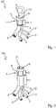
- FIG. 1 shows in a perspective side view of a first embodiment of an electrical line assembly 100, which has a line connector 1 according to a first embodiment and a plurality of, here exemplarily four, attached thereto electrical lines 2 in the form of eg stranded conductors.
- the line assembly 100 is particularly well suited for passage or end connector, as used for example in motor vehicles.
- the electrical conductors 4 of the lines 2 surrounded by an insulation jacket 3 are electrically connected on the one hand to the common line connector 1 and on the other hand to a respective electrical load (not shown).
- the in FIG. 1 shown line connector 1 is designed sleeve-shaped and forms in the interior, here a hollow cylindrical, receiving sleeve 5, in which the individual lines 2 are arranged together and thus summarized.
- the lines 2 within the receiving sleeve 5 form a common connection node.
- the receiving sleeve 5 can be structurally, but also functionally, divided into a compression section 6 and an insulating jacket section 7 along its sleeve longitudinal axis.
- the receiving sleeve 5 is radially compressed, whereby the lines 2, which are preferably stripped in Verpressabêt 6 by removing the insulation sheath 3, are pressed with the receiving sleeve 5.
- the lines 2 are mainly in Verpressabêt 6 with an inner surface of the receiving sleeve 5 and / or welded together. In the insulating jacket section 7, however, no welding takes place, since the heat input of the friction welding method used, which is described in more detail below, ideally does not occur up to there.
- the receiving sleeve 5 has at a first end face a first through-opening 8 and at an opposite, second end side a second through-opening 9, the lines 2 are guided in this embodiment of the first through-hole 8 forth through the receiving sleeve 5, that the cable ends received therein are substantially flush with each other and adjacent to the second passage opening 9 are arranged.
- the resulting welded connection V can be seen through the second through-opening 9 and can therefore be visually checked with optical means, such as a camera system, with regard to the welding quality.
- the line connector 1 and the receiving sleeve 5 in this embodiment adjacent to the second through hole 9 on an integrally molded, electrical contact element 10 which projects beyond the corresponding end outside and, like a cable lug, for electrical connection to a (not shown) support member , such as a body part of a motor vehicle, can be attached.
- a support member such as a body part of a motor vehicle.
- About the contact element 10 of the line connector 1 is also held mechanically (positive and / or positive fit) on the support element.
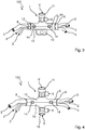
- FIG. 2 shows a further embodiment of the electrical lead assembly 100, which differs mainly by the fact that the insulating sheath portion 7 is formed longer and one opposite to that Compression section 6 has larger inner diameter.
- the contact element 10 is not explicitly provided here, because this is not required in every application.
- the welded joint V can be optically checked through the second passage opening 9.
- the insulating jacket section 7 additionally serves as a strain relief element of the individual insulated conductors 2 in the line arrangement 100. These can also be pressed together with insulation 3 in the receiving sleeve 5 in the insulating jacket section 7. This region 7 can also be used on the rear side for media-tight sealing of the stripped conductors 4 and of the weld connection region V to the direction of the lines 2.
- the insulating jacket section 7 can be embodied as a separate component made of metal, polymer material or ceramic
- FIG. 3 a further embodiment of the line arrangement 100 is shown, in which the line connector 1 additionally has a third passage opening 11, whose hole axis is arranged transversely to the (here common) hole axis of the first and second passage opening 8, 9.
- the hole axes are arranged perpendicular to each other, wherein the third passage opening 11 between the first and second passage opening 8, 9 is arranged.
- the first and second through-openings 8, 9 differ from the exemplary embodiments described above, since here the welded connection V is not formed by the second through-opening 9, but transversely through the third through-opening 11. Nevertheless, the weld V remains optically verifiable by the third passage opening 11.
- FIG. 3 also shows that the contact element 10 is arranged in this embodiment, again similar to a cable lug, opposite the third passage opening 11 and extends away from it in an opposite direction.
- the line connector is designed in several parts in this embodiment and has correspondingly two complementary shell elements 12, 13, which are fastened to each other via at least one (in this example, a total of two) coupling element 14.
- the coupling element 14 is configured here by way of example as a clipping, so that the shell elements 12, 13 are arranged around the lines 2 to be connected and then simply compressed and connected thereto.
- the connection of Shell elements 12, 13 can also be done by a winding tape, tape, shrink tubing or cable ties.
- the shell elements 12, 13 can be embodied as components of metal, polymer material or ceramic separately attached to the receiving sleeve 5.
- FIG. 4 shows a further embodiment of the conduit assembly 100, in which in addition a fourth passage opening 15 is formed, which here the third passage opening 11 opposite.
- a fourth passage opening 15 is formed, which here the third passage opening 11 opposite.
- the bundle of the lines 2 has such a large overall diameter that it is divided into two bundles, by a plastification of the joining partners of two opposite radial sides of a higher welding quality of the both the third and fourth through-hole 11th , 15 formed welded joint V causes.
- a hidden side fastening tab such as the contact element 10, or the like may be provided here.
- the welded connection V of the two passage openings 11, 15 are here designed so that in the compression section 6 of the through hole 11 only lines 2 with an electrical conductor 4 made of aluminum and in through hole 15 only lines 2 are welded to electrical conductors made of copper.
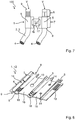
- the line connector 1 of in FIG. 5 shown embodiment is as a punched / bent part, here also exemplarily in one piece, and has one of the number of lines 2 corresponding number of individual receiving sleeves 5, whose respective inner diameter is slightly larger than the outer diameter of the therein male conductor 4 and der Isolationsmantels
- the receiving sleeves 5 here have different inner diameters for different cable diameters, this being merely optional or exemplary.
- the pressing portion 6 is at least partially tapered with respect to the insulating jacket portion 7.
- Verpressabêt 6 in FIG. 5 Above
- Verpressabites 6 are, as in the embodiments described above, in turn, the exposed conductor 4 welded to the receiving sleeves 5 and its inner surface, in which case a compression can be additionally provided.
- the respective receiving sleeves 5 are electrically connected to each other by a corresponding number of connecting portions 16, wherein the Connecting portions 16, in particular in this embodiment, sheet-shaped and integral with the receiving sleeves 5 are executed.
- the sheet material selected for this purpose is electrically conductive, so that the receiving sleeves 5 are electrically connected via the connecting portions 16.
- FIG. 5 Recognizable, in each case a free line end of the lines 2, in which the conductor 4 is exposed in sections, inserted into the respective receiving sleeve 5, for which the respective receiving sleeve 5 turn the (in FIG. 5 Lower) first passage opening 8 has.
- the respective receiving sleeve 5 but also the (in FIG. 5 upper) second through-hole 9, which serves to insert the welding tool, as will be explained in more detail below.
- the electrical contact element 10 in the form of a cable lug is hereby arranged by way of example on one of the receiving sleeves 5, which is either formed integrally with the receiving sleeve 5 or welded in at the welding operation explained below.
- FIG. 6 a variant embodiment of the line connector 1 is shown, in which the lines 2 are angled out of the receiving sleeves 5 away.
- the receiving sleeves 5 are executed even angled so that the hole axes of the first and second through holes 8, 9 are not on a common sleeve longitudinal axis, but on angled to each other, for example, rectangular.
- two receiving sleeves 5 are shown by way of example, however, more than two receiving sleeves 5 can also be provided in this embodiment variant.
- a variant of the contact or fastening element 10 is arranged for electrical connection to a (not shown and unspecified) electrical counter element or carrier element.
- the fastening element 10 has, in turn, similar to a cable lug, a through hole and a bolt inserted therethrough.
- the fastening element 10 may also be a welded-on or pressed-in threaded bolt or nut.
- the transition region between the passage opening 8 of the curved sleeve member 5 and the electrical conductor 2 can be sealed by a shrink tube 19.
- the securing element 17 overlaps with lateral tabs of the receiving sleeves 5 and is attached thereto, for example by means of clinching.
- FIG. 8 is a further, multi-part embodiment of the line connector 1 is shown. Because this does not necessarily have to be made in one piece, but this embodiment can also according to the two complementary shell elements 12, 13 have.
- FIG. 8 shows therefore a single shell element 12, which forms a part or a half of the respective receiving sleeves 5 respectively. Supplemented by a further shell element 13 then gives the example hollow cylindrical receiving sleeve 5. Adjacent to the second passage opening 9 of the receiving sleeve 5, the shell member 12 has within the part of the receiving sleeves 5, for example via clamping and / or fasteners 18 to bring into contact with the head 4, which is preferably a stranded conductor.
- the clamping and / or fastening element 18 is, for example, a protruding groove formed from the sheet metal material of the shell element 12, an adhesive tape or the like.
- FIG. 8 also once again to recognize the fastener 10, which is designed here as a simple passage opening.
- FIG. 8 indicated how the two shell elements 12, 13 can be connected together.
- coupling elements 14 are provided in the connecting section 16, which mechanically connect the shell elements 12, 13 to one another. This is done for example by means of gluing, clinching, jamming, etc.
- a sealing element 19 is provided on a flat side at least in lateral tabs of the line connector 1, that is then clamped between the two shell elements 12, 13 , seals and these glued together if necessary.
- the conductors 4 of the lines 2, of which two are shown here by way of example, are exposed in sections by removing the insulation jacket 3.
- the conductors 4 are again designed here as a stranded conductor.
- the lines 2 are then inserted from the first through-opening 8 into the respective receiving sleeve 5 and led to just below the second through-opening 9.
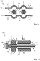
- the shell elements 12, 13 are arranged around the line ends and then, as in FIG. 9 indicated by arrows, put together.
- the shell elements 12, 13 mutually complement each other such that the ends of the exposed conductors 4, analogous to the one-piece embodiment variant, are arranged adjacent to the second through-opening 9.
- the receiving sleeves 5 are then radially compressed by a pressing tool with pressing jaws 110, 120 both in the one-piece and in the multi-part variant of the line connector 1, as shown in FIG. 10 indicated by arrows.
- Verpressabêt 6 while the exposed conductor 4 is brought into direct contact with the inner surface of the respective receiving sleeve 5.
- the insulating jacket section 7 one or more clamping elements 18 in the form of protruding into the receiving sleeve 5 projections in force and / or positive engagement with the insulation jacket 3 are brought.
- FIG. 11 shows the conduit assembly 100 thus produced in a sectional view. After cohesive joining, the resulting welded joint V is passed through the (in FIG. 11 left) second passage opening 9 optically, for example, with the aid of a camera system, tested.
- FIG. 12 the line assembly 100 produced in a plan view, wherein the cohesive connection V is directly recognizable by the second passage opening 9. It can also be seen that the first and second shell element 12, 13 have been joined to form an element by the welding operation with the friction welding tool 130. Furthermore, it is shown here that the receiving sleeves 5 of the shell elements 12, 13 are designed so that they are geometrically or positively matched to each other and thereby in the welding of the conductors 4 with the receiving sleeve 5 in the Verpressabêt 6 a displacement by occurring welding forces are partially prevented can.
Landscapes
- Engineering & Computer Science (AREA)
- Manufacturing & Machinery (AREA)
- Connections Effected By Soldering, Adhesion, Or Permanent Deformation (AREA)
Applications Claiming Priority (1)
| Application Number | Priority Date | Filing Date | Title |
|---|---|---|---|
| DE102017131352.4A DE102017131352B4 (de) | 2017-12-27 | 2017-12-27 | Leitungsverbinder sowie Herstellverfahren für eine elektrische Verbindung |
Publications (4)
| Publication Number | Publication Date |
|---|---|
| EP3506431A2 true EP3506431A2 (fr) | 2019-07-03 |
| EP3506431A3 EP3506431A3 (fr) | 2019-10-23 |
| EP3506431B1 EP3506431B1 (fr) | 2023-02-01 |
| EP3506431B8 EP3506431B8 (fr) | 2023-03-15 |
Family
ID=64746306
Family Applications (1)
| Application Number | Title | Priority Date | Filing Date |
|---|---|---|---|
| EP18214329.7A Active EP3506431B8 (fr) | 2017-12-27 | 2018-12-20 | Connecteur de conduite ainsi que procédé de fabrication d'une connexion électrique |
Country Status (4)
| Country | Link |
|---|---|
| US (1) | US11011902B2 (fr) |
| EP (1) | EP3506431B8 (fr) |
| CN (1) | CN109980369B (fr) |
| DE (1) | DE102017131352B4 (fr) |
Cited By (1)
| Publication number | Priority date | Publication date | Assignee | Title |
|---|---|---|---|---|
| WO2021180627A1 (fr) * | 2020-03-10 | 2021-09-16 | Lisa Dräxlmaier GmbH | Connecteur à soudure de friction et son procédé de production |
Families Citing this family (9)
| Publication number | Priority date | Publication date | Assignee | Title |
|---|---|---|---|---|
| DE102019104318C5 (de) * | 2019-02-20 | 2023-06-22 | Auto-Kabel Management Gmbh | Elektrischer Leiter sowie Verfahren zur Herstellung eines elektrischen Leiters |
| EP3790132B1 (fr) * | 2019-09-05 | 2025-11-26 | Aptiv Technologies AG | Connecteur d'épissure blindé en forme de y et son procédé d'assemblage |
| US11491935B2 (en) * | 2019-10-25 | 2022-11-08 | Sea Clear Power Inc. | Systems and methods for distribution of power in a marine vessel, ATVS, and vehicles |
| JP7453792B2 (ja) * | 2020-01-16 | 2024-03-21 | 日本航空電子工業株式会社 | 固定具、固定方法、ケーブル組立体及び構造体 |
| DE102020004613A1 (de) | 2020-07-29 | 2022-02-03 | Sumitomo Wiring Systems, Ltd. | Gespleisstes kabel, insbesondere gespleisstes hochspannungskabel, und verfahren zum spleissen eines kabels, insbesondere eines hochspannungskabels |
| CN115036775B (zh) * | 2022-06-21 | 2025-10-31 | 吉安市鑫通联电路股份有限公司 | 一种电子元件加工用分线机构 |
| CN115241711B (zh) * | 2022-07-27 | 2023-05-05 | 杭州德鸿电力科技有限公司 | 一种电缆熔接式接头热熔焊接装置及其工艺 |
| CN115986466A (zh) * | 2022-12-13 | 2023-04-18 | 东莞市中迈新能源科技有限公司 | 一体式储能连接器及其制作工艺 |
| CN118554187B (zh) * | 2024-07-26 | 2024-10-01 | 国网浙江省电力有限公司嵊泗县供电公司 | 一种电缆接线器 |
Family Cites Families (32)
| Publication number | Priority date | Publication date | Assignee | Title |
|---|---|---|---|---|
| US2478082A (en) * | 1945-10-24 | 1949-08-02 | Aircraft Marine Prod Inc | Electrical connector |
| US3001000A (en) * | 1958-05-28 | 1961-09-19 | Chance Co Ab | Electrical compression connectors |
| US3134844A (en) * | 1962-05-14 | 1964-05-26 | Aluminum Co Of America | Electrical connectors |
| US3387080A (en) * | 1966-07-25 | 1968-06-04 | Burndy Corp | Splice connector with locking insert |
| JPS5081992U (fr) * | 1973-11-30 | 1975-07-14 | ||
| GB1536163A (en) * | 1976-04-08 | 1978-12-20 | Standard Telephones Cables Ltd | Jointing arrangement for coaxial cores |
| DE2723029C2 (de) | 1977-05-21 | 1985-06-27 | Robert Bosch Gmbh, 7000 Stuttgart | Elektrische Verbindung von mindestens zum Teil lackierten Drähten |
| JPS58147179U (ja) * | 1982-03-29 | 1983-10-03 | いすゞ自動車株式会社 | 中継接続用スリ−ブ |
| US4745239A (en) * | 1986-09-09 | 1988-05-17 | Teledyne Industries, Inc. | Multiple wire joining device and method |
| JPH0256367U (fr) * | 1988-10-18 | 1990-04-24 | ||
| DE9217344U1 (de) * | 1992-12-18 | 1993-02-18 | Mannesmann Kienzle GmbH, 7730 Villingen-Schwenningen | Abzweigverbindung für elektrische Leitungen |
| JPH06260218A (ja) * | 1993-03-04 | 1994-09-16 | Sumitomo Wiring Syst Ltd | 電線接合方法 |
| DE19908031B4 (de) | 1999-02-24 | 2009-08-13 | Auto-Kabel Management Gmbh | Verbindung eines elektrischen Aluminiumkabels mit einem aus Kupfer oder dergleichen Metall bestehenden Anschlußteil |
| JP4235185B2 (ja) * | 2005-02-24 | 2009-03-11 | 矢崎総業株式会社 | アースプレート及びこれに同軸線を取り付けるための治具 |
| DE102005039462A1 (de) * | 2005-08-20 | 2007-03-01 | Daimlerchrysler Ag | Polklemme mit Stromableitung und Sicherungsanordnung |
| DE102006021422B8 (de) * | 2006-05-05 | 2008-06-26 | Schunk Ultraschalltechnik Gmbh | Verfahren zur Herstellung eines Durchgangs- oder Endknotens sowie Durchgangs- oder Endknoten |
| JP5008492B2 (ja) * | 2007-08-01 | 2012-08-22 | 株式会社オートネットワーク技術研究所 | シールドコネクタ |
| EP2037544A3 (fr) * | 2007-09-06 | 2010-08-25 | J.S.T. Mfg. Co., Ltd. | Kit d'assemblage d'un connecteur électrique et harnais de câbles blindés |
| US7438597B1 (en) * | 2008-04-23 | 2008-10-21 | International Business Machines Corporation | EMC clamp for three exit backshell |
| JP5342884B2 (ja) * | 2009-01-13 | 2013-11-13 | 矢崎総業株式会社 | 電線接続ユニット |
| DE102009029339A1 (de) * | 2009-09-10 | 2011-03-24 | Lisa Dräxlmaier GmbH | Leitungsverbinder zum elektrischen Verbinden wenigstens zweier elektrischer Leiter, elektrische Leitung mit einem solchen Leitungsverbinder sowie Verfahren zum elektrischen Verbinden zweier elektrischer Leiter |
| JP5066243B2 (ja) * | 2010-06-08 | 2012-11-07 | ヒロセ電機株式会社 | 電気コネクタ、およびツイストペアケーブルと電気コネクタとの接続方法 |
| DE102010060767A1 (de) | 2010-08-18 | 2012-02-23 | Schunk Sonosystems Gmbh | Verfahren und Anordnung zum Verschweißen von elektrischen Leitern |
| BR112015004896A2 (pt) * | 2012-10-31 | 2017-07-04 | Delphi Tech Inc | conjunto de arnês de fio, sistema de comunicação, e, método para emendar cabos de fio blindados entre si |
| EP2735397B1 (fr) * | 2012-11-23 | 2018-01-17 | Nexans | Procédé de connection électrique d'une pièce de contact à un conducteur électrique |
| DE102013101876B3 (de) * | 2013-02-26 | 2014-06-12 | Innovations- und Informationszentrum Schneiden und Fügen e.V. | Verfahren zum stoffschlüssigen Fügen eines Kabels mit einem Anschlusselement sowie konfiguriertes Kabel |
| DE102013013151A1 (de) | 2013-08-08 | 2015-02-12 | Lisa Dräxlmaier GmbH | Vefahren zum elektrischen Verbinden der Litze eines elektrischen Leiters mit einem Leiteranschlusselement sowie konfektionierte elektrische Leitung |
| CA2861914C (fr) * | 2013-10-04 | 2020-03-10 | Thomas & Betts International Llc | Joints de fils a compression |
| DE102014002643B4 (de) | 2014-02-27 | 2024-08-08 | Auto-Kabel Management Gmbh | Hülse sowie Verfahren zur Herstellung einer Verbindung |
| JP6402958B1 (ja) * | 2017-02-10 | 2018-10-10 | 株式会社オートネットワーク技術研究所 | 端子付き電線 |
| JP6974135B2 (ja) * | 2017-11-24 | 2021-12-01 | 矢崎総業株式会社 | 端子接続方法 |
| JP6978294B2 (ja) * | 2017-11-30 | 2021-12-08 | 矢崎総業株式会社 | 端子接続方法及び端子 |
-
2017
- 2017-12-27 DE DE102017131352.4A patent/DE102017131352B4/de active Active
-
2018
- 2018-12-20 EP EP18214329.7A patent/EP3506431B8/fr active Active
- 2018-12-20 CN CN201811559805.4A patent/CN109980369B/zh active Active
- 2018-12-20 US US16/227,294 patent/US11011902B2/en active Active
Cited By (2)
| Publication number | Priority date | Publication date | Assignee | Title |
|---|---|---|---|---|
| WO2021180627A1 (fr) * | 2020-03-10 | 2021-09-16 | Lisa Dräxlmaier GmbH | Connecteur à soudure de friction et son procédé de production |
| EP4118717A1 (fr) * | 2020-03-10 | 2023-01-18 | Lisa Dräxlmaier GmbH | Connecteur à soudure de friction et son procédé de production |
Also Published As
| Publication number | Publication date |
|---|---|
| EP3506431B1 (fr) | 2023-02-01 |
| CN109980369A (zh) | 2019-07-05 |
| US11011902B2 (en) | 2021-05-18 |
| US20190199079A1 (en) | 2019-06-27 |
| DE102017131352A1 (de) | 2019-06-27 |
| CN109980369B (zh) | 2024-02-13 |
| DE102017131352B4 (de) | 2024-02-08 |
| EP3506431A3 (fr) | 2019-10-23 |
| EP3506431B8 (fr) | 2023-03-15 |
Similar Documents
| Publication | Publication Date | Title |
|---|---|---|
| EP3506431A2 (fr) | Connecteur de conduite, ensemble de conduites électrique ainsi que procédé de fabrication d'une connexion électrique | |
| EP1885025B1 (fr) | Dispositif de raccordement électrique d'au moins deux conducteurs principaux isolés d'un câble d'alimentation électrique, en particulier borne de dérivation | |
| DE102017114994B3 (de) | Verfahren zum herstellen einer elektrischen leitungsanordnung | |
| DE102020130894A1 (de) | Modulverbinder und Berührschutzelement | |
| DE3225175A1 (de) | Abschirmanschluss | |
| DE112014002495T5 (de) | Verbindungsstruktur für Metallklemmenanschlussstücke | |
| AT513003B1 (de) | Verbindung eines elektrischen Kabels mit einem Kontaktteil | |
| WO2017167463A1 (fr) | Conducteur électrique pourvu d'une douille à souder maintenue par frottement | |
| EP3769370A1 (fr) | Procédé d'établissement d'une liaison entre un élément de raccordement électrique destiné à un réseau de bord de véhicule automobile et un câble du réseau de bord de véhicule automobile | |
| EP3329566B1 (fr) | Dispositif antidéflagrant et procédé de fabrication de celui-ci | |
| DE69700563T2 (de) | Steckerelement und Herstellungsverfahren dafür | |
| EP4304900B1 (fr) | Connexion électrique | |
| EP4080685A1 (fr) | Câble électrique confectionné et agencement de connecteur enfichable | |
| DE102006050708A1 (de) | Elektrischer Flachbandleiter | |
| EP1870961A1 (fr) | Raccordement de câbles | |
| EP3701601B1 (fr) | Procédé destiné à assembler par pénétration de matière un câble électrique à une partie de contact électrique et système de câble électrique | |
| DE102013013368B4 (de) | Verfahren zur Herstellung einer elektrischen Verbindung sowie elektrische Verbindung | |
| EP1158611B1 (fr) | Connecteur de câble | |
| DE102005052309B4 (de) | Anschlußbolzen, Anschlußelement und elektrisch leitende Kupplungsvorrichtung | |
| EP2923416B1 (fr) | Dispositif pour le raccordement ou l'assemblage électrique d'au moins un conducteur d'un câble d'alimentation en énergie | |
| DE102015106466A1 (de) | Elektrische Leitungsanordnung für ein Fahrzeug-Bordnetz und Verfahren zur Herstellung einer solchen Leitungsanordnung | |
| DE102022202282A1 (de) | Potentialverteiler sowie Verfahren zur elektrischen Kontaktierung von mehreren abisolierten Leiterenden | |
| EP4150654B1 (fr) | Dispositif de déconnexion électrique, système comprenant un dispositif de déconnexion et procédé de production d'un dispositif de déconnexion | |
| EP1887656B1 (fr) | Connecteur électrique | |
| WO2002097928A1 (fr) | Dispositif de raccordement de cables |
Legal Events
| Date | Code | Title | Description |
|---|---|---|---|
| PUAI | Public reference made under article 153(3) epc to a published international application that has entered the european phase |
Free format text: ORIGINAL CODE: 0009012 |
|
| STAA | Information on the status of an ep patent application or granted ep patent |
Free format text: STATUS: THE APPLICATION HAS BEEN PUBLISHED |
|
| AK | Designated contracting states |
Kind code of ref document: A2 Designated state(s): AL AT BE BG CH CY CZ DE DK EE ES FI FR GB GR HR HU IE IS IT LI LT LU LV MC MK MT NL NO PL PT RO RS SE SI SK SM TR |
|
| AX | Request for extension of the european patent |
Extension state: BA ME |
|
| PUAL | Search report despatched |
Free format text: ORIGINAL CODE: 0009013 |
|
| AK | Designated contracting states |
Kind code of ref document: A3 Designated state(s): AL AT BE BG CH CY CZ DE DK EE ES FI FR GB GR HR HU IE IS IT LI LT LU LV MC MK MT NL NO PL PT RO RS SE SI SK SM TR |
|
| AX | Request for extension of the european patent |
Extension state: BA ME |
|
| RIC1 | Information provided on ipc code assigned before grant |
Ipc: H01R 13/502 20060101ALN20190919BHEP Ipc: H01R 4/20 20060101ALI20190919BHEP Ipc: H01R 4/62 20060101ALN20190919BHEP Ipc: H01R 11/32 20060101ALN20190919BHEP Ipc: H01R 4/18 20060101AFI20190919BHEP |
|
| STAA | Information on the status of an ep patent application or granted ep patent |
Free format text: STATUS: REQUEST FOR EXAMINATION WAS MADE |
|
| 17P | Request for examination filed |
Effective date: 20200422 |
|
| RBV | Designated contracting states (corrected) |
Designated state(s): AL AT BE BG CH CY CZ DE DK EE ES FI FR GB GR HR HU IE IS IT LI LT LU LV MC MK MT NL NO PL PT RO RS SE SI SK SM TR |
|
| STAA | Information on the status of an ep patent application or granted ep patent |
Free format text: STATUS: EXAMINATION IS IN PROGRESS |
|
| 17Q | First examination report despatched |
Effective date: 20210510 |
|
| RIC1 | Information provided on ipc code assigned before grant |
Ipc: H01R 13/502 20060101ALN20220705BHEP Ipc: H01R 11/32 20060101ALN20220705BHEP Ipc: H01R 4/62 20060101ALN20220705BHEP Ipc: H02G 15/18 20060101ALI20220705BHEP Ipc: H02G 1/14 20060101ALI20220705BHEP Ipc: H01R 4/20 20060101ALI20220705BHEP Ipc: H01R 4/18 20060101AFI20220705BHEP |
|
| GRAP | Despatch of communication of intention to grant a patent |
Free format text: ORIGINAL CODE: EPIDOSNIGR1 |
|
| STAA | Information on the status of an ep patent application or granted ep patent |
Free format text: STATUS: GRANT OF PATENT IS INTENDED |
|
| INTG | Intention to grant announced |
Effective date: 20220822 |
|
| GRAS | Grant fee paid |
Free format text: ORIGINAL CODE: EPIDOSNIGR3 |
|
| GRAA | (expected) grant |
Free format text: ORIGINAL CODE: 0009210 |
|
| STAA | Information on the status of an ep patent application or granted ep patent |
Free format text: STATUS: THE PATENT HAS BEEN GRANTED |
|
| REG | Reference to a national code |
Ref country code: DE Ref legal event code: R108 Ref document number: 502018011538 Country of ref document: DE Ref legal event code: R108 |
|
| AK | Designated contracting states |
Kind code of ref document: B1 Designated state(s): AL AT BE BG CH CY CZ DE DK EE ES FI FR GB GR HR HU IE IS IT LI LT LU LV MC MK MT NL NO PL PT RO RS SE SI SK SM TR |
|
| REG | Reference to a national code |
Ref country code: GB Ref legal event code: FG4D Free format text: NOT ENGLISH |
|
| REG | Reference to a national code |
Ref country code: CH Ref legal event code: EP Ref country code: AT Ref legal event code: REF Ref document number: 1547163 Country of ref document: AT Kind code of ref document: T Effective date: 20230215 |
|
| REG | Reference to a national code |
Ref country code: IE Ref legal event code: FG4D Free format text: LANGUAGE OF EP DOCUMENT: GERMAN |
|
| RBV | Designated contracting states (corrected) |
Designated state(s): AL AT BE BG CH CY CZ DK EE ES FI FR GB GR HR HU IE IS IT LI LT LU LV MC MK MT NL NO PL PT RO RS SE SI SK SM TR |
|
| REG | Reference to a national code |
Ref country code: CH Ref legal event code: PK Free format text: BERICHTIGUNG B8 |
|
| REG | Reference to a national code |
Ref country code: DE Ref legal event code: R107 Ref document number: 502018011538 Country of ref document: DE Ref country code: DE |
|
| REG | Reference to a national code |
Ref country code: LT Ref legal event code: MG9D |
|
| REG | Reference to a national code |
Ref country code: NL Ref legal event code: MP Effective date: 20230201 |
|
| PG25 | Lapsed in a contracting state [announced via postgrant information from national office to epo] |
Ref country code: RS Free format text: LAPSE BECAUSE OF FAILURE TO SUBMIT A TRANSLATION OF THE DESCRIPTION OR TO PAY THE FEE WITHIN THE PRESCRIBED TIME-LIMIT Effective date: 20230201 Ref country code: PT Free format text: LAPSE BECAUSE OF FAILURE TO SUBMIT A TRANSLATION OF THE DESCRIPTION OR TO PAY THE FEE WITHIN THE PRESCRIBED TIME-LIMIT Effective date: 20230601 Ref country code: NO Free format text: LAPSE BECAUSE OF FAILURE TO SUBMIT A TRANSLATION OF THE DESCRIPTION OR TO PAY THE FEE WITHIN THE PRESCRIBED TIME-LIMIT Effective date: 20230501 Ref country code: NL Free format text: LAPSE BECAUSE OF FAILURE TO SUBMIT A TRANSLATION OF THE DESCRIPTION OR TO PAY THE FEE WITHIN THE PRESCRIBED TIME-LIMIT Effective date: 20230201 Ref country code: LV Free format text: LAPSE BECAUSE OF FAILURE TO SUBMIT A TRANSLATION OF THE DESCRIPTION OR TO PAY THE FEE WITHIN THE PRESCRIBED TIME-LIMIT Effective date: 20230201 Ref country code: LT Free format text: LAPSE BECAUSE OF FAILURE TO SUBMIT A TRANSLATION OF THE DESCRIPTION OR TO PAY THE FEE WITHIN THE PRESCRIBED TIME-LIMIT Effective date: 20230201 Ref country code: HR Free format text: LAPSE BECAUSE OF FAILURE TO SUBMIT A TRANSLATION OF THE DESCRIPTION OR TO PAY THE FEE WITHIN THE PRESCRIBED TIME-LIMIT Effective date: 20230201 Ref country code: ES Free format text: LAPSE BECAUSE OF FAILURE TO SUBMIT A TRANSLATION OF THE DESCRIPTION OR TO PAY THE FEE WITHIN THE PRESCRIBED TIME-LIMIT Effective date: 20230201 |
|
| PG25 | Lapsed in a contracting state [announced via postgrant information from national office to epo] |
Ref country code: SE Free format text: LAPSE BECAUSE OF FAILURE TO SUBMIT A TRANSLATION OF THE DESCRIPTION OR TO PAY THE FEE WITHIN THE PRESCRIBED TIME-LIMIT Effective date: 20230201 Ref country code: PL Free format text: LAPSE BECAUSE OF FAILURE TO SUBMIT A TRANSLATION OF THE DESCRIPTION OR TO PAY THE FEE WITHIN THE PRESCRIBED TIME-LIMIT Effective date: 20230201 Ref country code: IS Free format text: LAPSE BECAUSE OF FAILURE TO SUBMIT A TRANSLATION OF THE DESCRIPTION OR TO PAY THE FEE WITHIN THE PRESCRIBED TIME-LIMIT Effective date: 20230601 Ref country code: GR Free format text: LAPSE BECAUSE OF FAILURE TO SUBMIT A TRANSLATION OF THE DESCRIPTION OR TO PAY THE FEE WITHIN THE PRESCRIBED TIME-LIMIT Effective date: 20230502 Ref country code: FI Free format text: LAPSE BECAUSE OF FAILURE TO SUBMIT A TRANSLATION OF THE DESCRIPTION OR TO PAY THE FEE WITHIN THE PRESCRIBED TIME-LIMIT Effective date: 20230201 |
|
| PG25 | Lapsed in a contracting state [announced via postgrant information from national office to epo] |
Ref country code: SM Free format text: LAPSE BECAUSE OF FAILURE TO SUBMIT A TRANSLATION OF THE DESCRIPTION OR TO PAY THE FEE WITHIN THE PRESCRIBED TIME-LIMIT Effective date: 20230201 Ref country code: RO Free format text: LAPSE BECAUSE OF FAILURE TO SUBMIT A TRANSLATION OF THE DESCRIPTION OR TO PAY THE FEE WITHIN THE PRESCRIBED TIME-LIMIT Effective date: 20230201 Ref country code: EE Free format text: LAPSE BECAUSE OF FAILURE TO SUBMIT A TRANSLATION OF THE DESCRIPTION OR TO PAY THE FEE WITHIN THE PRESCRIBED TIME-LIMIT Effective date: 20230201 Ref country code: DK Free format text: LAPSE BECAUSE OF FAILURE TO SUBMIT A TRANSLATION OF THE DESCRIPTION OR TO PAY THE FEE WITHIN THE PRESCRIBED TIME-LIMIT Effective date: 20230201 Ref country code: CZ Free format text: LAPSE BECAUSE OF FAILURE TO SUBMIT A TRANSLATION OF THE DESCRIPTION OR TO PAY THE FEE WITHIN THE PRESCRIBED TIME-LIMIT Effective date: 20230201 |
|
| P01 | Opt-out of the competence of the unified patent court (upc) registered |
Effective date: 20231017 |
|
| PG25 | Lapsed in a contracting state [announced via postgrant information from national office to epo] |
Ref country code: SK Free format text: LAPSE BECAUSE OF FAILURE TO SUBMIT A TRANSLATION OF THE DESCRIPTION OR TO PAY THE FEE WITHIN THE PRESCRIBED TIME-LIMIT Effective date: 20230201 |
|
| PLBE | No opposition filed within time limit |
Free format text: ORIGINAL CODE: 0009261 |
|
| STAA | Information on the status of an ep patent application or granted ep patent |
Free format text: STATUS: NO OPPOSITION FILED WITHIN TIME LIMIT |
|
| 26N | No opposition filed |
Effective date: 20231103 |
|
| PG25 | Lapsed in a contracting state [announced via postgrant information from national office to epo] |
Ref country code: SI Free format text: LAPSE BECAUSE OF FAILURE TO SUBMIT A TRANSLATION OF THE DESCRIPTION OR TO PAY THE FEE WITHIN THE PRESCRIBED TIME-LIMIT Effective date: 20230201 |
|
| PG25 | Lapsed in a contracting state [announced via postgrant information from national office to epo] |
Ref country code: IT Free format text: LAPSE BECAUSE OF FAILURE TO SUBMIT A TRANSLATION OF THE DESCRIPTION OR TO PAY THE FEE WITHIN THE PRESCRIBED TIME-LIMIT Effective date: 20230201 |
|
| REG | Reference to a national code |
Ref country code: CH Ref legal event code: PL |
|
| PG25 | Lapsed in a contracting state [announced via postgrant information from national office to epo] |
Ref country code: LU Free format text: LAPSE BECAUSE OF NON-PAYMENT OF DUE FEES Effective date: 20231220 |
|
| PG25 | Lapsed in a contracting state [announced via postgrant information from national office to epo] |
Ref country code: MC Free format text: LAPSE BECAUSE OF FAILURE TO SUBMIT A TRANSLATION OF THE DESCRIPTION OR TO PAY THE FEE WITHIN THE PRESCRIBED TIME-LIMIT Effective date: 20230201 |
|
| REG | Reference to a national code |
Ref country code: BE Ref legal event code: MM Effective date: 20231231 |
|
| PG25 | Lapsed in a contracting state [announced via postgrant information from national office to epo] |
Ref country code: MC Free format text: LAPSE BECAUSE OF FAILURE TO SUBMIT A TRANSLATION OF THE DESCRIPTION OR TO PAY THE FEE WITHIN THE PRESCRIBED TIME-LIMIT Effective date: 20230201 Ref country code: LU Free format text: LAPSE BECAUSE OF NON-PAYMENT OF DUE FEES Effective date: 20231220 |
|
| REG | Reference to a national code |
Ref country code: IE Ref legal event code: MM4A |
|
| PG25 | Lapsed in a contracting state [announced via postgrant information from national office to epo] |
Ref country code: IE Free format text: LAPSE BECAUSE OF NON-PAYMENT OF DUE FEES Effective date: 20231220 |
|
| PG25 | Lapsed in a contracting state [announced via postgrant information from national office to epo] |
Ref country code: BE Free format text: LAPSE BECAUSE OF NON-PAYMENT OF DUE FEES Effective date: 20231231 |
|
| PG25 | Lapsed in a contracting state [announced via postgrant information from national office to epo] |
Ref country code: CH Free format text: LAPSE BECAUSE OF NON-PAYMENT OF DUE FEES Effective date: 20231231 |
|
| PG25 | Lapsed in a contracting state [announced via postgrant information from national office to epo] |
Ref country code: IE Free format text: LAPSE BECAUSE OF NON-PAYMENT OF DUE FEES Effective date: 20231220 Ref country code: CH Free format text: LAPSE BECAUSE OF NON-PAYMENT OF DUE FEES Effective date: 20231231 Ref country code: BE Free format text: LAPSE BECAUSE OF NON-PAYMENT OF DUE FEES Effective date: 20231231 |
|
| PG25 | Lapsed in a contracting state [announced via postgrant information from national office to epo] |
Ref country code: BG Free format text: LAPSE BECAUSE OF FAILURE TO SUBMIT A TRANSLATION OF THE DESCRIPTION OR TO PAY THE FEE WITHIN THE PRESCRIBED TIME-LIMIT Effective date: 20230201 |
|
| PG25 | Lapsed in a contracting state [announced via postgrant information from national office to epo] |
Ref country code: BG Free format text: LAPSE BECAUSE OF FAILURE TO SUBMIT A TRANSLATION OF THE DESCRIPTION OR TO PAY THE FEE WITHIN THE PRESCRIBED TIME-LIMIT Effective date: 20230201 |
|
| REG | Reference to a national code |
Ref country code: AT Ref legal event code: MM01 Ref document number: 1547163 Country of ref document: AT Kind code of ref document: T Effective date: 20231220 |
|
| PG25 | Lapsed in a contracting state [announced via postgrant information from national office to epo] |
Ref country code: AT Free format text: LAPSE BECAUSE OF NON-PAYMENT OF DUE FEES Effective date: 20231220 |
|
| PG25 | Lapsed in a contracting state [announced via postgrant information from national office to epo] |
Ref country code: CY Free format text: LAPSE BECAUSE OF FAILURE TO SUBMIT A TRANSLATION OF THE DESCRIPTION OR TO PAY THE FEE WITHIN THE PRESCRIBED TIME-LIMIT; INVALID AB INITIO Effective date: 20181220 |
|
| PG25 | Lapsed in a contracting state [announced via postgrant information from national office to epo] |
Ref country code: HU Free format text: LAPSE BECAUSE OF FAILURE TO SUBMIT A TRANSLATION OF THE DESCRIPTION OR TO PAY THE FEE WITHIN THE PRESCRIBED TIME-LIMIT; INVALID AB INITIO Effective date: 20181220 |
|
| PG25 | Lapsed in a contracting state [announced via postgrant information from national office to epo] |
Ref country code: TR Free format text: LAPSE BECAUSE OF FAILURE TO SUBMIT A TRANSLATION OF THE DESCRIPTION OR TO PAY THE FEE WITHIN THE PRESCRIBED TIME-LIMIT Effective date: 20230201 |
|
| PGFP | Annual fee paid to national office [announced via postgrant information from national office to epo] |
Ref country code: GB Payment date: 20251001 Year of fee payment: 8 |
|
| PGFP | Annual fee paid to national office [announced via postgrant information from national office to epo] |
Ref country code: FR Payment date: 20251008 Year of fee payment: 8 |