EP3508152B1 - Système d'instrument chirurgical flexible stérilisable - Google Patents
Système d'instrument chirurgical flexible stérilisable Download PDFInfo
- Publication number
- EP3508152B1 EP3508152B1 EP17845507.7A EP17845507A EP3508152B1 EP 3508152 B1 EP3508152 B1 EP 3508152B1 EP 17845507 A EP17845507 A EP 17845507A EP 3508152 B1 EP3508152 B1 EP 3508152B1
- Authority
- EP
- European Patent Office
- Prior art keywords
- structural
- surgical instrument
- securely connected
- flexible surgical
- transmission mechanism
- Prior art date
- Legal status (The legal status is an assumption and is not a legal conclusion. Google has not performed a legal analysis and makes no representation as to the accuracy of the status listed.)
- Active
Links
Images






Classifications
-
- A—HUMAN NECESSITIES
- A61—MEDICAL OR VETERINARY SCIENCE; HYGIENE
- A61B—DIAGNOSIS; SURGERY; IDENTIFICATION
- A61B34/00—Computer-aided surgery; Manipulators or robots specially adapted for use in surgery
- A61B34/30—Surgical robots
-
- A—HUMAN NECESSITIES
- A61—MEDICAL OR VETERINARY SCIENCE; HYGIENE
- A61B—DIAGNOSIS; SURGERY; IDENTIFICATION
- A61B34/00—Computer-aided surgery; Manipulators or robots specially adapted for use in surgery
- A61B34/70—Manipulators specially adapted for use in surgery
-
- A—HUMAN NECESSITIES
- A61—MEDICAL OR VETERINARY SCIENCE; HYGIENE
- A61B—DIAGNOSIS; SURGERY; IDENTIFICATION
- A61B17/00—Surgical instruments, devices or methods
- A61B2017/00477—Coupling
-
- A—HUMAN NECESSITIES
- A61—MEDICAL OR VETERINARY SCIENCE; HYGIENE
- A61B—DIAGNOSIS; SURGERY; IDENTIFICATION
- A61B34/00—Computer-aided surgery; Manipulators or robots specially adapted for use in surgery
- A61B34/30—Surgical robots
- A61B2034/301—Surgical robots for introducing or steering flexible instruments inserted into the body, e.g. catheters or endoscopes
-
- A—HUMAN NECESSITIES
- A61—MEDICAL OR VETERINARY SCIENCE; HYGIENE
- A61B—DIAGNOSIS; SURGERY; IDENTIFICATION
- A61B34/00—Computer-aided surgery; Manipulators or robots specially adapted for use in surgery
- A61B34/30—Surgical robots
- A61B2034/302—Surgical robots specifically adapted for manipulations within body cavities, e.g. within abdominal or thoracic cavities
-
- A—HUMAN NECESSITIES
- A61—MEDICAL OR VETERINARY SCIENCE; HYGIENE
- A61B—DIAGNOSIS; SURGERY; IDENTIFICATION
- A61B34/00—Computer-aided surgery; Manipulators or robots specially adapted for use in surgery
- A61B34/30—Surgical robots
- A61B2034/305—Details of wrist mechanisms at distal ends of robotic arms
Definitions
- the present invention relates to a sterilizable flexible surgical instrument system, belonging to the field of medical instruments.
- Multi-port laparoscopic minimally invasive surgery has occupied an important position in surgery because of it having small wound and rapid postoperative recovery.
- the existing da Vinci surgical robot of the Intuitive Surgical, Inc. assists doctors in implementing the multi-port laparoscopic minimally invasive surgery and has achieved great commercial success.
- WO 2009/094670 A1 relates to systems and methods for force sensing using continuum robots.
- a sterilizable flexible surgical instrument system comprising a flexible continuous body structure comprising a distal structural body, a middle connecting body and a proximal structural body, the distal structural body comprising at least one distal structural segment comprising a distal spacing disk, a distal fixing disk and structural backbones, the proximal structural body comprising a proximal structural segment comprising a proximal spacing disk, a proximal fixing disk and structural backbones, and the proximal structural segment being linked to the distal structural segment via the middle connecting body, wherein the flexible surgical instrument system further comprises a transmission unit, the transmission unit comprises a transmission mechanism fixing plate arranged at distal side of the middle connecting body, a transmission mechanism for converting a rotary motion input into a linear motion output is arranged on the transmission mechanism fixing plate, output ends of the transmission mechanism are respectively securely connected to ends of different driving backbones via adaptors, and other ends of the driving backbone
- the number of the proximal structural segments is equal to the number of the distal structural segments.
- the middle connecting body comprises two channel fixing plates and a structural backbone guide channel provided between the two channel fixing plates; and the structural backbones of the distal structural segment are securely connected, in one-to-one correspondence, to or are the same as the structural backbones of the proximal structural segment, one end of each of the structural backbones is securely connected to the proximal fixing disk, passing through the proximal spacing disk, the structural backbone guide channel and the distal spacing disk in sequence, and the other end of the structural backbone is securely connected to the distal fixing disk.
- the transmission mechanism comprises a gear transmission mechanism;
- the gear transmission mechanism comprises a driving gear, a rack, a slider, a guide rod, and a guide rod base;
- the guide rod is securely connected to the transmission mechanism fixing plate or a flexible surgical instrument front end plate via the guide rod base,
- the slider is slidably connected to the guide rod, the slider is securely connected to the rack, the rack is securely connected to the middle of the bundle of steering structural backbones;
- the rack meshes with the driving gear;
- the driving gear is securely sheathed over a driving shaft, and a rear end of the driving shaft is rotatably supported on the flexible surgical instrument rear end plate located in rear of the proximal structural body and is securely connected with a male coupling.
- the middle connecting body comprises two channel fixing plates and a structural backbone guide channel provided between the two channel fixing plates; and each of the steering structural backbones passes through the two steering structural backbone guide channels, with one end of the steering structural backbone guide channel being securely connected to the channel fixing plate, and the other end of the steering structural backbone guide channel being securely connected to the guide rod base arranged on the transmission mechanism fixing plate.
- a guide rod is arranged between the two channel fixing plates, and the adaptor is slidably connected to the guide rod.
- the transmission mechanism comprises a pulley transmission mechanism;
- the pulley transmission mechanism comprises a driving pulley, a driven pulley, a cable, a slider, a guide rod, and a guide rod base;
- two driven pulleys are provided, and are respectively rotatably arranged on the transmission mechanism fixing plate;
- two ends of the cable respectively pass around the driven pulley and are then securely connected to the driving pulley;
- the slider is securely connected to the cable between the two driven pulleys, the slider is slidably connected to the guide rod, and the guide rod is supported on the transmission mechanism fixing plate via the guide rod base;
- the slider is securely connected to the middle of the bundle of steering structural backbones, and the two ends of the bundle of steering structural backbones are respectively connected to a linear motion mechanism which comprises the adaptors;
- the driving pulley is securely sheathed over a driving shaft, and a rear end of the driving shaft is rotatably supported on the flexible surgical instrument rear end plate arranged in rear
- the middle connecting body comprises two channel fixing plates; and the linear motion mechanism comprises a second guide rod securely connected to the two channel fixing plates and a adaptor slidably connected to the second guide rod, with a front end of the adaptor being securely connected to the steering structural backbone, and a rear end of the adaptor being securely connected to the driving backbone.
- the middle connecting body comprises two channel fixing plates and a structural backbone guide channel provided between the two channel fixing plates; and each of the steering structural backbones passes through the two steering structural backbone guide channels, with one end of the steering structural backbone guide channel being securely connected to the channel fixing plate, and the other end of the steering structural backbone guide channel being securely connected to a support frame of the transmission mechanism fixing plate.
- a surgical end effector is arranged at a front end of the distal structural body, a actuation wire of the surgical end effector passes through the distal structural body, the other end is connected to the end effector driving mechanism, and the surgical end effector driving mechanism implements motion control over the surgical end effector by means of physically pushing and pulling the actuation wire.
- the surgical end effector driving mechanism comprises a threaded rod, a nut, a guide sleeve base, a guide sleeve, a push-pull rod and a male coupling;
- the threaded rod is rotatably connected to the flexible surgical instrument rear end plate in rear of the proximal structural body, and a rear end of the threaded rod is securely connected to the male coupling;
- the nut is threadedly connected to the threaded rod;
- a front end of the guide sleeve base is securely connected to the guide sleeve, and a rear end of the guide sleeve base is securely connected to the flexible surgical instrument rear end plate;
- an inner hole of the guide sleeve is a square hole in which the nut can only slide and cannot rotate; and a rear end of the push rod is securely connected to the nut, and a front end of the push rod is securely connected to the actuation wire.
- the flexible surgical instrument system further comprises a flexible surgical instrument housing, and the transmission mechanism fixing plate, the flexible surgical instrument front end plate and the flexible surgical instrument rear end plate are all securely connected to the flexible surgical instrument housing.
- the flexible surgical instrument system further comprises a motor driving unit, wherein the motor driving unit is connected to the flexible surgical instrument via a sterile barrier;
- the motor driving unit comprises a motor driving unit shell, a motor fixing plate, and a plurality of motors securely connected to the motor fixing plate, with an output shaft of each of the motors being securely connected with a second male coupling;
- the sterile barrier comprises a sterile barrier support plate, a sterile barrier cover, and a plurality of female couplings rotatably connected to the sterile barrier support plate, with a front end of the female coupling being connected to the male coupling, and a rear end of the female coupling being connected to the second male coupling; and a sterile membrane is securely connected to the sterile barrier cover.
- a front end of the motor fixing plate is provided with a first connecting pin seat
- a rear end of the sterile barrier support plate is provided with a second connecting pin seat, the first connecting pin seat being connected to the second connecting pin seat via a pin hole.
- the flexible surgical instrument system further comprises a motor driving unit, wherein the motor driving unit is connected to the flexible surgical instrument via a sterile barrier;
- the motor driving unit comprises a motor driving unit shell, a motor fixing plate, and a second motor securely connected to the motor fixing plate, the motor fixing plate being rotatably connected to the motor driving unit shell, an inner wall of the motor driving unit shell being securely connected with an inner ring gear, an output shaft of the second motor being securely connected with a gear, and the gear meshing with the inner ring gear.
- the flexible surgical instrument system further comprises a motor driving unit shell and a linear module, wherein the motor driving unit shell is directly or indirectly connected to the flexible surgical instrument housing; and the linear module comprises a bracket body, a third motor securely connected to the bracket body, and a linear feed mechanism securely connected to an output shaft of the third motor, with an output end of the linear feed mechanism being securely connected to the motor driving unit shell, and the third motor driving the motor driving unit shell via the linear feed mechanism to drive the motor driving unit, the sterile barrier and the flexible surgical instrument to perform a linear motion.
- the motor driving unit shell is directly or indirectly connected to the flexible surgical instrument housing
- the linear module comprises a bracket body, a third motor securely connected to the bracket body, and a linear feed mechanism securely connected to an output shaft of the third motor, with an output end of the linear feed mechanism being securely connected to the motor driving unit shell, and the third motor driving the motor driving unit shell via the linear feed mechanism to drive the motor driving unit, the sterile barrier and the flexible surgical instrument to perform a linear motion.
- the linear feed mechanism comprises a lead screw rotatably connected to the bracket body, the lead screw is sheathed with a second slider which is threadedly fitted with the lead screw, the bracket body is provided with a linear sliding groove, and the second slider is slidably arranged in the linear sliding groove; and the output shaft of the third motor is securely connected to the lead screw via a coupling.
- the present disclosure can be applied to the single-port endoscopic surgery, and can also be applied to the natural orifice transluminal non-invasive surgery.
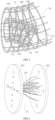
- the present invention comprises a flexible surgical instrument 10, and the flexible surgical instrument 10 comprises a flexible continuous body structure and a transmission unit 21, the flexible continuous body structure being composed of a distal structural body 11 (as shown in Fig. 2 ), a proximal structural body 16 (as shown in Fig. 3 ) and a middle connecting body 15 (as shown in Fig. 5 ).
- the distal structural body 11 is linked to the proximal structural body 16 via the middle connecting body 15; and the transmission unit 21 is linked to the proximal structural body 16, and when the transmission unit 21 drives the proximal structural body 16 to turn in any direction, the distal structural body 11 correspondingly turns in the opposite direction.
- the distal structural body 11 comprises a first distal structural segment 12 and a second distal structural segment 13, wherein the first distal structural segment 12 comprises first distal spacing disks 121, a first distal fixing disk 122 and first segment structural backbones 123; and the second distal structural segment 13 comprises second distal spacing disks 131, a second distal fixing disk 132 and second segment structural backbones 133.
- the first distal spacing disks 121 and the second distal spacing disks 131 are respectively distributed at intervals in the first distal structural segment 12 and the second distal structural segment 13, in order to prevent the first segment structural backbones 123 and the second segment structural backbones 133 from being destabilized when being pushed.
- the proximal structural body 16 comprises a first proximal structural segment 17 and a second proximal structural segment 18, wherein the first proximal structural segment 17 comprises first proximal spacing disks 171, a first proximal fixing disk 172 and first segment structural backbones 173; and the second proximal structural segment 18 comprises second proximal spacing disks 181, a second proximal fixing disk 182, and second segment structural backbones 183, wherein the first proximal spacing disks 171 and the second proximal spacing disks 181 are respectively distributed at intervals in the first proximal structural segment 17 and the second proximal structural segment 18, in order to prevent the first segment structural backbones 173 and the second segment structural backbones 183 from being destabilized when being pushed.
- the first segment structural backbones 173 on the first proximal structural segment 17 are securely connected, in one-to-one correspondence, to or are the same as the first segment structural backbones 123 on the first distal structural segment 12; and the second segment structural backbones 183 on the second proximal structural segment 18 are securely connected, in one-to-one correspondence, to or are the same as the second segment structural backbones 133 on the second distal structural segment 13.
- the number of structural backbones is three or more.
- the middle connecting body 15 comprises two channel fixing plates 152 and a structural backbone guide channel 151 fixedly connected between the two channel fixing plates 152.
- One end of the first segment structural backbone 173 (123) is securely connected to the first proximal fixing disk 172, and the other end passes through the first proximal spacing disks 171, the structural backbone guide channel 151 and the first distal spacing disks 121 in sequence and is then securely connected to the first distal fixing disk 122.
- the structural backbone guide channel 151 functions to maintain the shape of the structural backbone under a pushing or pulling force.
- the number of the distal structural segments comprised in the distal structural body 11 and the number of the proximal structural segments comprised in the proximal structural body 16 may also be one or more than two, but the number of the proximal structural segments must be consistent with the number of the distal structural segments.
- the distal structural segments comprised in the distal structural body 11 are connected in series, that is, the second segment structural backbone passes through the first distal fixing disk and the first distal spacing disks (and can also pass through the first segment structural backbone if the first segment structural backbone is of a tubular structure); and when the number of the proximal structural segments comprised in the proximal structural body 16 is two or more, series connection, independent arrangement or nested arrangement (as shown in Fig. 3 ), etc. may be applied between the structural segments.
- the transmission unit 21 comprises a transmission mechanism fixing plate 24 arranged at distal side of the middle connecting body 15, and a gear transmission mechanism 22 arranged between the transmission mechanism fixing plate 24 and the flexible surgical instrument front end plate 105 or a pulley transmission mechanism 27 arranged on the transmission mechanism fixing plate 24, both the gear transmission mechanism 22 and the pulley transmission mechanism 27 being used for converting a rotary motion input into a linear motion output.
- an output end of the gear transmission mechanism 22 is respectively securely connected to one ends of two driving backbones 211 via two adaptors 23; and when the pulley transmission mechanism 27 is used, an output end of the pulley transmission mechanism 27 is respectively securely connected to one end of two driving backbones 211 via two linear motion mechanisms 28 arranged between the two channel fixing plates 152.
- the other ends of the two driving backbones 211 respectively pass through the first proximal spacing disk 171 and are then securely connected to the first proximal fixing disk 172, or pass through the second proximal spacing disk 181 and are then securely connected to the second proximal fixing disk 182.
- a pair of driving backbones 211 can be pushed or pulled cooperatively so as to implement turning of the first proximal structural segment 17 or the second proximal structural segment 18.
- the number of driving backbones 211 is eight, four of which are securely connected to the first proximal fixing disk 172, and the other four are securely connected to the second proximal fixing disk 182.
- gear transmission mechanisms 22 or pulley transmission mechanisms 27 can cooperatively push or pull a pair of driving backbones 211, four gear transmission mechanisms 22 or four pulley transmission mechanisms 27 are provided in this embodiment, in which two of the gear transmission mechanisms 22 or the pulley transmission mechanisms 27 are used to drive the first proximal structural segment 17 to perform a turning motion in any direction, and when the first proximal structural segment 17 turns in a certain direction, the first distal structural segment 12 will turn in the opposite direction in a certain proportional relationship (determined by the distribution radius of the first segment structural backbone 173 and the first segment structural backbone 123 together); and the other two gear transmission mechanisms 22 or pulley transmission mechanisms 27 are used to drive the second proximal structural segment 18 to perform a turning motion in any direction, and when the second proximal structural segment 18 turns in a certain direction, the second distal structural segment 13 will turn in the opposite direction in a certain proportional relationship (determined by the distribution radius of the second segment structural backbone 183 and the second segment structural backbone 133 together).
- the gear transmission mechanism 22 comprises a driving gear 221, a rack 222, a slider 223, a guide rod 224, a guide rod base 225 and a steering structural backbone 226, wherein the guide rod 224 is securely connected to the transmission mechanism fixing plate 24 or the flexible surgical instrument front end plate 105 via the guide rod base 225, the slider 223 is slidably connected to the guide rod 224, the slider 223 is securely connected to the rack 222, the rack 222 is securely connected to the middle of a bundle of steering structural backbones 226, and two ends of the bundle of steering structural backbones 226 extend backward through the transmission mechanism fixing plate 24 and are then connected to one of the driving backbones 211 via one of the adaptors 23, respectively.
- the rack 222 meshes with the driving gear 221, the driving gear 221 is securely sheathed over the driving shaft 213, the rear end of the driving shaft 213 passes through the transmission mechanism fixing plate 24, the channel fixing plate 152, and the flexible surgical instrument rear end plate 106 arranged in rear of the proximal structural body 16 in sequence, and is securely connected to the male coupling 212, and the driving shaft 213 is rotatably connected to the flexible surgical instrument rear end plate 106.
- a plurality of guide rods are provided between two channel fixing plates 152, and the adaptor 23 is slidably connected to the guide rod, so as to ensure that the adaptor 23 always performs a linear motion, preventing the adaptor 23 from turning over when the driving backbone 211 is pushed or pulled.
- each of the steering structural backbones 226 passes through the two steering structural backbone guide channels 228, with one end of the steering structural backbone guide channel being securely connected to the channel fixing plate 152, and the other end being securely connected to the guide rod base 225, and the steering structural backbone guide channel 228 functions to keep the shape of the steering structural backbone 226 unchanged under a pushing or pulling force.
- the pulley transmission mechanism 27 comprises a driving pulley 271, a driven pulley 272, a cable 273, a slider 275, a guide rod 274, a guide rod base 277 and a steering structural backbone 276, wherein two driven pulleys 272 are provided and respectively rotatably arranged on the transmission mechanism fixing plate 24, two ends of the cable 273 respectively pass around a driven pulley 272 and are then securely connected to the driving pulley 271, the driving pulley 271 is securely sheathed over the driving shaft 213, the rear end of the driving shaft 213 pass through the transmission mechanism fixing plate 24, the channel fixing plate 152, and the flexible surgical instrument rear end plate 106 arranged in rear of the proximal structural body 16 in sequence, and is securely connected to the male coupling 212, and the driving shaft 213 is rotatably connected to the flexible surgical instrument rear end plate 106.
- a slider 275 is securely connected to the cable 273 between two driven pulleys 272, the slider 275 is slidably connected to the guide rod 274, and the guide rod 274 is fixedly supported on the transmission mechanism fixing plate 24 via the guide rod base 277.
- the slider 275 is securely connected to the middle of a bundle of steering structural backbones 276, and two ends of the bundle of steering structural backbones 276 extend backward through the transmission mechanism fixing plate 24 and are respectively connected to the linear motion mechanism 28.
- the linear motion mechanism 28 comprises a guide rod 281 securely connected between the two channel fixing plates 152 and a adaptor 282 slidably connected to the guide rod 281, with a front end of the adaptor 282 being securely connected to the steering structural backbone 276, and a rear end of the adaptor being securely connected to the driving backbone 211.
- each of the steering structural backbones 276 passes through the two steering structural backbone guide channels 278, with one end of the steering structural backbone guide channel being securely connected to the channel fixing plate 152, and the other end of the steering structural backbone being securely connected to a support frame 279 fixedly arranged at a front side of the transmission mechanism fixing plate 24, and the steering structural backbone guide channel 278 functions to keep the shape of the steering structural backbone 276 unchanged under a pushing or pulling force.
- the front end of the distal structural body 11 is provided with a surgical end effector 101 (as shown in Fig. 2 ), a actuation wire 102 of the surgical end effector 101 passes through the distal structural body 11, and the other end is connected to the surgical end effector driving mechanism 25.
- the surgical end effector driving mechanism 25 implements control over the surgical end effector 101 (e.g., surgical forceps) by means of physically pushing or pulling the actuation wire 102.
- the actuation wire 102 may also transfer various forms of energy, such as electrical energy and highfrequency vibrations, to achieve specific surgical functions of the surgical end effector 101. As shown in Fig.
- the surgical end effector driving mechanism 25 comprises a threaded rod 251, a nut 252, a guide sleeve base 253, a guide sleeve 254, a push-pull rod 255 and a male coupling 256, wherein the threaded rod 251 is rotatably connected to the center of the flexible surgical instrument rear end plate 106, a rear end of the threaded rod is securely connected to the male coupling 256, and the nut 252 is threadedly connected to the threaded rod 251; a front end of the guide sleeve base 253 is securely connected to the guide sleeve 254, and a rear end of the guide sleeve base is securely connected to the flexible surgical instrument rear end plate 106; an inner hole of the guide sleeve 254 is a square hole and forms a restriction on the nut 252, so that the nut 252 can only slide in the inner hole of the guide sleeve 254 and cannot rotate; and a rear end of
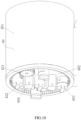
- the present disclosure further comprises a motor driving unit 40, and the motor driving unit 40 is connected to the flexible surgical instrument 10 via the sterile barrier 30.
- the flexible surgical instrument 10 further comprises a flexible surgical instrument housing 107, and the channel fixing plate 152, the transmission mechanism fixing plate 24 and the flexible surgical instrument rear end plate 106 are all securely connected to the flexible surgical instrument housing 107.
- the motor driving unit 40 comprises a motor driving unit shell 401, a motor fixing plate 402, and a plurality of first motors (not shown in the figure) securely connected to the motor fixing plate 402, with an output shaft of each of the first motors being securely connected to one of the male couplings 403. As shown in Fig.
- the sterile barrier 30 comprises a sterile barrier support plate 301, a sterile barrier cover 302 and a plurality of female couplings 303 rotatably connected to the sterile barrier support plate 301, with a rear end of the female coupling 303 being connected to the male coupling 403, and a front end of the female coupling being connected to the male coupling 212 or the male coupling 256.
- a front side of the motor fixing plate 402 is provided with a connecting pin seat 404, and a rear side of the sterile barrier support plate 301 is correspondingly provided with a connecting pin seat 304, the connecting pin seat 404 being quickly connected to the connecting pin seat 304 via a pin hole; and the sterile barrier cover 302 is detachably connected to the surgical instrument housing 107.
- a sterile membrane (not shown in the figure) is securely connected on the sterile barrier cover 302 to isolate the sterilizable parts (such as the flexible surgical instrument 10 and other parts in front of the sterile barrier 30) from the unsterilized parts (such as the motor driving unit 40 and other parts in rear of the sterile barrier), in order to ensure the clinical practicability of surgery.
- the gear 421 When the output shaft of the second motor rotates, the gear 421 is driven to rotate, and the gear 421 circumferentially travels along the inner ring gear 422, so as to drive all structures, other than the motor driving unit shell 401 and the inner ring gear 422 to rotate around the axis of the inner ring gear 422, thereby implementing the rotation of the flexible surgical instrument 10 as a whole and achieving control over the roll angle of the distal structural body 101 and the surgical end effector 30.
- the present disclosure further comprises a linear module 50 (the linear module 50 being also separated from the sterilized part via the sterile membrane 230), which comprises a bracket body 501 with a sliding groove, a lead screw 502 is rotatably provided on the bracket body 501, the lead screw 502 is sheathed with a slider 503 which is threadedly fitted with the lead screw 502 and is slidably provided in the sliding groove, one end of the bracket body 501 is provided with a motor 504, and an output shaft of the motor 504 is securely connected to the lead screw 502 via a coupling.
- the motor driving unit housing 401 is securely connected to the slider 503. When the output shaft of the motor 504 rotates, the slider 503 drives the motor driving unit housing 401 to perform linear movement along the sliding groove, so as to implement the feed motion of the flexible surgical instrument 10.
- an envelope 103 is provided over the outside of the distal structural body 11 and functions to improve the smoothness of the distal structural body 11 entering a natural orifice or a surgical incision in the human body.
- a sheath 60 (as shown in Fig. 2 ) may also be provided over the outside of the envelope 103.
- the sheath 60 is fixed at a single incision in the abdominal cavity, and the distal structural body 11, together with the envelope 103 and the surgical end effector 101, can freely pass through a through hole in the sheath 60 for the passage of the surgical instrument and access to the surgical site.
- the sheath 60 may also be a flexible sheath that can more easily extend into various natural orifices of the human body and adaptively change shape as the shape of the orifices, one end of the flexible sheath is fixed at the entrance of the orifice, and the distal structural body 11, together with the envelope 103 and the surgical end effector 101, can freely pass through a through hole in the flexible sheath for the passage of the surgical instrument and access to the surgical site.
Landscapes
- Health & Medical Sciences (AREA)
- Surgery (AREA)
- Engineering & Computer Science (AREA)
- Life Sciences & Earth Sciences (AREA)
- Medical Informatics (AREA)
- Robotics (AREA)
- Biomedical Technology (AREA)
- Heart & Thoracic Surgery (AREA)
- Nuclear Medicine, Radiotherapy & Molecular Imaging (AREA)
- Molecular Biology (AREA)
- Animal Behavior & Ethology (AREA)
- General Health & Medical Sciences (AREA)
- Public Health (AREA)
- Veterinary Medicine (AREA)
- Manipulator (AREA)
- Surgical Instruments (AREA)
Claims (18)
- Système d'instrument chirurgical flexible stérilisable, comprenant une structure de corps continue flexible comprenant un corps structural distal (11), un corps de liaison central (15) et un corps structural proximal (16), le corps structural distal (11) comprenant au moins un segment structural distal (12, 13) comprenant un disque d'espacement distal (121, 131), un disque de fixation distal (122, 132) et des armatures structurales (123, 133), le corps structural proximal (16) comprenant un segment structural proximal (17, 18) comprenant un disque d'espacement proximal (171, 181), un disque de fixation proximal (172, 182) et des armatures structurales (173, 183), et le segment structural proximal (17, 18) étant lié au segment structural distal (12, 13) par l'intermédiaire du corps de liaison central (15), dans lequel le système d'instrument chirurgical flexible comprend en outre une unité de transmission (21), l'unité de transmission (21) comprend une plaque de fixation (24) de mécanisme de transmission agencée du côté distal du corps de liaison central (15), un mécanisme de transmission (22) pour convertir une entrée de mouvement de rotation en une sortie de mouvement linéaire est agencé sur la plaque de fixation (24) de mécanisme de transmission, les extrémités de sortie du mécanisme de transmission (22) sont respectivement solidement reliées aux extrémités de différents armatures d'entraînement (211) par l'intermédiaire d'adaptateurs (23), et d'autres extrémités des armatures d'entraînement (211) passent à travers le disque d'espacement proximal (171, 181) et sont solidement reliées au disque de fixation proximal (172, 182) ;
caractérisé en ce quele mécanisme de transmission (22) comprend au moins un faisceau d'armatures structurales de direction (226, 276), et le faisceau d'armatures structurales de direction (226, 276) transmet la sortie de mouvement linéaire ;deux extrémités du faisceau d'armatures structurales de direction (226, 276) s'étendent vers l'arrière à travers la plaque de fixation (24) de mécanisme de transmission et sont respectivement reliées à l'adaptateur correspondant (23). - Système d'instrument chirurgical flexible stérilisable selon la revendication 1, dans lequel le corps de liaison central (15) comprend deux plaques de fixation (152) de canal et un canal de guidage (151) d'armature structurale disposé entre les deux plaques de fixation (152) de canal ; et les armatures structurales (123, 133) du segment structural distal (12, 13) sont solidement reliées, en correspondance biunivoque, aux armatures structurales (173, 183) du segment structural proximal (17, 18) ou sont les mêmes que celles-ci, une extrémité de chacune des armatures structurales (173, 183) est solidement reliée au disque de fixation proximal (172, 182), en passant à travers le disque d'espacement proximal (171, 181), le canal de guidage (151) d'armature structurale et le disque d'espacement distal (121, 131) en séquence, et l'autre extrémité des armatures structurales (123, 133) est solidement reliée au disque de fixation distal (122, 132).
- Système d'instrument chirurgical flexible stérilisable selon la revendication 1, dans lequel le mécanisme de transmission comprend un mécanisme de transmission à engrenages (22) ; le mécanisme de transmission à engrenages (22) comprend une roue menante (221), une crémaillère (222), un coulisseau (223), une tige de guidage (224) et une base (225) de tige de guidage ; la tige de guidage (224) est solidement reliée à la plaque de fixation (24) de mécanisme de transmission ou à une plaque d'extrémité avant (105) d'instrument chirurgical flexible par l'intermédiaire de la base (225) de tige de guidage, le coulisseau (223) est relié de manière coulissante à la tige de guidage (224), le coulisseau (223) est solidement relié à la crémaillère (222), la crémaillère (222) est solidement reliée au milieu du faisceau des armatures structurales de direction (226) ; la crémaillère (222) s'engrène avec la roue menante (221) ; et la roue menante (221) est fermement manchonnée sur un arbre d'entraînement (213), et une extrémité arrière de l'arbre d'entraînement (213) est supportée de manière rotative sur la plaque d'extrémité arrière (106) d'instrument chirurgical flexible située à l'arrière du corps structural proximal (16) et est solidement reliée à un couplage mâle (212).
- Système d'instrument chirurgical flexible stérilisable selon la revendication 3, dans lequel le corps de liaison central (15) comprend deux plaques de fixation (152) de canal et un canal de guidage (151) d'armature structurale disposé entre les deux plaques de fixation (152) de canal ; et chacune des armatures structurales de direction (226) passe à travers les deux canaux de guidage (228) d'armature structurale de direction, une extrémité des canaux de guidage (228) d'armature structurale de direction étant solidement reliée à la plaque de fixation (152) de canal, et l'autre extrémité des canaux de guidage (228) d'armature structurale de direction étant solidement reliée à la base (225) de tige de guidage agencée sur la plaque de fixation (24) de mécanisme de transmission.
- Système d'instrument chirurgical flexible stérilisable selon la revendication 4, dans lequel une tige de guidage est agencée entre les deux plaques de fixation (152) de canal, et l'adaptateur (23) est relié de manière coulissante à la tige de guidage.
- Système d'instrument chirurgical flexible stérilisable selon la revendication 1, dans lequel le mécanisme de transmission comprend un mécanisme de transmission à poulies (27) ; le mécanisme de transmission à poulies (27) comprend une poulie motrice (271), une poulie menée (272), un câble (273), un coulisseau (275), une tige de guidage (274) et une base (277) de tige de guidage ; deux poulies menées (272) sont disposées, et sont respectivement agencées de manière rotative sur la plaque de fixation (24) de mécanisme de transmission ; deux extrémités du câble (273) passent respectivement autour de la poulie menée (272) et sont ensuite solidement reliées à la poulie motrice (271) ; le coulisseau (275) est solidement relié au câble (273) entre les deux poulies menées (272), le coulisseau (275) est relié de manière coulissante à la tige de guidage (274), et la tige de guidage (274) est supportée sur la plaque de fixation (24) de mécanisme de transmission par l'intermédiaire de la base (277) de tige de guidage ; le coulisseau (275) est solidement relié au milieu du faisceau d'armatures structurales de direction (276), et les deux extrémités du faisceau d'armatures structurales de direction (226, 276) sont respectivement reliées à un mécanisme de mouvement linéaire (28) qui comprend les adaptateurs (23) ; et la poulie motrice (271) est fermement ajustée sur un arbre d'entraînement (213), et une extrémité arrière de l'arbre d'entraînement (213) est supportée de manière rotative sur la plaque d'extrémité arrière (106) d'instrument chirurgical flexible agencée à l'arrière du corps structural proximal (16) et est solidement reliée à un couplage mâle (212).
- Système d'instrument chirurgical flexible stérilisable selon la revendication 6, dans lequel le corps de liaison central (15) comprend deux plaques de fixation (152) de canal ; et le mécanisme de mouvement linéaire (28) comprend une seconde tige de guidage (281) solidement reliée aux deux plaques de fixation (152) de canal et un adaptateur (282) relié de manière coulissante à la seconde tige de guidage (281), une extrémité avant de l'adaptateur (282) étant solidement reliée aux armatures structurales de direction (276), et une extrémité arrière de l'adaptateur (282) étant solidement reliée à l'armature d'entraînement (211).
- Système d'instrument chirurgical flexible stérilisable selon la revendication 6, dans lequel le corps de liaison central (15) comprend deux plaques de fixation (152) de canal et un canal de guidage (151) d'armature structurale disposé entre les deux plaques de fixation (152) de canal ; et chacune des armatures structurales de direction (276) passe à travers les deux canaux de guidage (278) d'armature structurale de direction, une extrémité des canaux de guidage (278) d'armature structurale de direction étant solidement reliée à la plaque de fixation (152) de canal, et l'autre extrémité des canaux de guidage (278) d'armature structurale de direction étant solidement reliée à un cadre de support (279) de la plaque de fixation (24) de mécanisme de transmission.
- Système d'instrument chirurgical flexible stérilisable selon la revendication 1, dans lequel un effecteur d'extrémité chirurgical (101) est agencé sur une extrémité avant du corps structural distal (11), un fil d'actionnement (102) de l'effecteur d'extrémité chirurgical (101) passe à travers le corps structural distal (11), l'autre extrémité est reliée au mécanisme d'entraînement (25) d'effecteur d'extrémité chirurgical, et le mécanisme d'entraînement (25) d'effecteur d'extrémité chirurgical met en oeuvre une commande de mouvement sur l'effecteur d'extrémité chirurgical (101) au moyen d'une poussée ou d'une traction physique du fil d'actionnement (102).
- Système d'instrument chirurgical flexible stérilisable selon la revendication 9, dans lequel le mécanisme d'entraînement (25) d'effecteur d'extrémité chirurgical comprend une tige filetée (251), un écrou (252), une base (253) de manchon de guidage, un manchon de guidage (254), une tige de poussée et de traction (255) et un couplage mâle (256) ; la tige filetée (251) est reliée de manière rotative à la plaque d'extrémité arrière (106) d'instrument chirurgical flexible à l'arrière du corps structural proximal (16), et une extrémité arrière de la tige filetée (251) est solidement reliée au couplage mâle (256) ; l'écrou (252) est relié par filetage à la tige filetée (251) ; une extrémité avant de la base (253) de manchon de guidage est solidement reliée au manchon de guidage (254), et une extrémité arrière de la base (253) de manchon de guidage est solidement reliée à la plaque d'extrémité arrière (106) d'instrument chirurgical flexible ; un trou intérieur du manchon de guidage (254) est un trou carré dans lequel l'écrou (252) ne peut que coulisser et ne peut pas tourner ; et une extrémité arrière de la tige de poussée et de traction (255) est solidement reliée à l'écrou (252), et une extrémité avant de la tige de poussée et de traction (255) est solidement reliée au fil d'actionnement (102).
- Système d'instrument chirurgical flexible stérilisable selon la revendication 3, comprenant en outre un boîtier (107) d'instrument chirurgical flexible, dans lequel la plaque de fixation (24) de mécanisme de transmission, la plaque d'extrémité avant (105) d'instrument chirurgical flexible et la plaque d'extrémité arrière (106) d'instrument chirurgical flexible sont toutes solidement reliées au boîtier (107) d'instrument chirurgical flexible.
- Système d'instrument chirurgical flexible stérilisable selon la revendication 6, comprenant en outre un boîtier (107) d'instrument chirurgical flexible, dans lequel la plaque de fixation (24) de mécanisme de transmission et la plaque d'extrémité arrière (106) d'instrument chirurgical flexible sont toutes deux solidement reliées au boîtier (107) d'instrument chirurgical flexible.
- Système d'instrument chirurgical flexible stérilisable selon la revendication 11 ou 12, comprenant en outre une unité d'entraînement (40) de moteurs, dans lequel l'unité d'entraînement (40) de moteurs est reliée à l'instrument chirurgical flexible par l'intermédiaire d'une barrière stérile (30) ; l'unité d'entraînement (40) de moteurs comprend une coque (401) d'unité d'entraînement de moteurs, une plaque de fixation (402) de moteurs, et une pluralité de moteurs solidement reliés à la plaque de fixation (402) de moteurs, un arbre de sortie de chacun des moteurs étant solidement relié à un second couplage mâle (403) ; la barrière stérile (30) comprend une plaque-support (301) de barrière stérile, un couvercle (302) de barrière stérile, et une pluralité de couplages femelles (303) reliés de manière rotative à la plaque-support (301) de barrière stérile, une extrémité avant du couplage femelle (303) étant reliée au couplage mâle (212, 256), et une extrémité arrière du couplage femelle (303) étant reliée au second couplage mâle (403) ; et une membrane stérile est solidement reliée au couvercle (302) de barrière stérile.
- Système d'instrument chirurgical flexible stérilisable selon la revendication 13, dans lequel une extrémité avant de la plaque de fixation (402) de moteurs est munie d'un premier siège de broche de liaison (404), et une extrémité arrière de la plaque-support (301) de barrière stérile est munie d'un second siège de broche de liaison (304), le premier siège de broche de liaison (404) étant relié au second siège de broche de liaison (304) par l'intermédiaire d'un trou de broche.
- Système d'instrument chirurgical flexible stérilisable selon la revendication 11 ou 12, comprenant en outre une unité d'entraînement (40) de moteurs, dans lequel l'unité d'entraînement (40) de moteurs est reliée à l'instrument chirurgical flexible par l'intermédiaire d'une barrière stérile (30) ; et l'unité d'entraînement (40) de moteurs comprend une coque (401) d'unité d'entraînement de moteurs, une plaque de fixation (402) de moteurs, et un deuxième moteur solidement relié à la plaque de fixation (402) de moteurs, la plaque de fixation (402) de moteurs étant reliée de manière rotative à la coque (401) d'unité d'entraînement de moteurs, une paroi intérieure de la coque (401) d'unité d'entraînement de moteurs étant solidement reliée à une couronne à denture intérieure (422), un arbre de sortie du deuxième moteur étant solidement relié à un engrenage (421), et l'engrenage (421) s'engrenant avec la couronne à denture intérieure (422).
- Système d'instrument chirurgical flexible stérilisable selon la revendication 11 ou 12, comprenant en outre une coque (401) d'unité d'entraînement de moteurs et un module linéaire (50), dans lequel la coque (401) d'unité d'entraînement de moteurs est directement ou indirectement reliée au boîtier (107) d'instrument chirurgical flexible ; et le module linéaire (50) comprend un corps de support (501), un troisième moteur (504) solidement relié au corps de support (501), et un mécanisme d'avance linéaire solidement relié à un arbre de sortie du troisième moteur (504), une extrémité de sortie du mécanisme d'avance linéaire étant solidement reliée à la coque (401) d'unité d'entraînement de moteurs, et le troisième moteur (504) entraînant la coque (401) d'unité d'entraînement de moteurs par l'intermédiaire du mécanisme d'avance linéaire pour amener l'unité d'entraînement (40) de moteurs, la barrière stérile (30) et l'instrument chirurgical flexible, à effectuer un mouvement linéaire.
- Système d'instrument chirurgical flexible stérilisable selon la revendication 16, dans lequel le mécanisme d'avance linéaire comprend une vis-mère (502) reliée de manière rotative au corps de support (501), la vis-mère (502) est recouverte d'un second coulisseau (503) qui est couplé par filetage avec la vis-mère (502), le corps de support (501) est muni d'une rainure de coulissement linéaire, et le second coulisseau est agencé de manière coulissante dans la rainure de coulissement linéaire ; et l'arbre de sortie du troisième moteur (504) est solidement relié à la vis-mère (502) par l'intermédiaire d'un couplage.
- Système d'instrument chirurgical flexible stérilisable selon l'une quelconque des revendications 1-12, dans lequel le nombre de segments structuraux proximaux (17, 18) est égal au nombre de segments structuraux distaux (12, 13).
Applications Claiming Priority (3)
| Application Number | Priority Date | Filing Date | Title |
|---|---|---|---|
| CN201610796089.6A CN106236270B (zh) | 2016-08-31 | 2016-08-31 | 一种结构骨冗余布置的柔性手术工具系统 |
| CN201610796082.4A CN106344157B (zh) | 2016-08-31 | 2016-08-31 | 一种可消毒的柔性手术工具系统 |
| PCT/CN2017/099856 WO2018041205A1 (fr) | 2016-08-31 | 2017-08-31 | Système d'instrument chirurgical flexible stérilisable |
Publications (3)
| Publication Number | Publication Date |
|---|---|
| EP3508152A1 EP3508152A1 (fr) | 2019-07-10 |
| EP3508152A4 EP3508152A4 (fr) | 2020-06-24 |
| EP3508152B1 true EP3508152B1 (fr) | 2024-10-23 |
Family
ID=61301429
Family Applications (1)
| Application Number | Title | Priority Date | Filing Date |
|---|---|---|---|
| EP17845507.7A Active EP3508152B1 (fr) | 2016-08-31 | 2017-08-31 | Système d'instrument chirurgical flexible stérilisable |
Country Status (3)
| Country | Link |
|---|---|
| US (1) | US11684432B2 (fr) |
| EP (1) | EP3508152B1 (fr) |
| WO (1) | WO2018041205A1 (fr) |
Families Citing this family (3)
| Publication number | Priority date | Publication date | Assignee | Title |
|---|---|---|---|---|
| WO2021243047A1 (fr) * | 2020-05-29 | 2021-12-02 | Virginia Tech Intellectual Properties Inc. | Manipulateur de continuum extensible |
| EP4173576A4 (fr) * | 2020-06-30 | 2024-07-24 | Beijing Surgerii Robotics Company Limited | Instrument corporel continu et robot chirurgical |
| CN113693729B (zh) * | 2021-08-04 | 2022-08-05 | 常州唯精医疗机器人有限公司 | 器械驱动盒及微创手术机器人 |
Family Cites Families (12)
| Publication number | Priority date | Publication date | Assignee | Title |
|---|---|---|---|---|
| US7331967B2 (en) * | 2002-09-09 | 2008-02-19 | Hansen Medical, Inc. | Surgical instrument coupling mechanism |
| EP2008594B1 (fr) * | 2003-03-13 | 2011-04-20 | Medtronic, Inc. | Appareil d'engagement temporaire de tissu corporel |
| US8992422B2 (en) * | 2006-03-23 | 2015-03-31 | Ethicon Endo-Surgery, Inc. | Robotically-controlled endoscopic accessory channel |
| US20130090763A1 (en) | 2008-01-25 | 2013-04-11 | The Trustees Of Columibia University In The City Of The City Of New York | Systems and methods for force sensing in a robot |
| CN103085083B (zh) | 2013-01-07 | 2015-06-24 | 汪雯 | 可弯转可伸缩的柔性连续体机械结构 |
| CN103315781B (zh) * | 2013-07-10 | 2015-03-18 | 上海交通大学 | 内窥镜无创手术系统 |
| JP6081309B2 (ja) * | 2013-07-24 | 2017-02-15 | オリンパス株式会社 | 医療用マニピュレータ |
| CN103707322B (zh) * | 2013-12-31 | 2016-04-20 | 汪雯 | 可弯转可伸缩的柔性连续体机械结构 |
| US10548630B2 (en) * | 2014-02-11 | 2020-02-04 | Vanderbilt University | System, method, and apparatus for configuration, design, and operation of an active cannula robot |
| CN104546048B (zh) * | 2015-01-19 | 2016-11-16 | 上海逸思医疗科技有限公司 | 一种外科器械及其控弯机构 |
| CN106236270B (zh) | 2016-08-31 | 2019-04-23 | 北京术锐技术有限公司 | 一种结构骨冗余布置的柔性手术工具系统 |
| CN106344157B (zh) | 2016-08-31 | 2019-04-23 | 北京术锐技术有限公司 | 一种可消毒的柔性手术工具系统 |
-
2017
- 2017-08-31 WO PCT/CN2017/099856 patent/WO2018041205A1/fr not_active Ceased
- 2017-08-31 US US16/329,745 patent/US11684432B2/en active Active
- 2017-08-31 EP EP17845507.7A patent/EP3508152B1/fr active Active
Also Published As
| Publication number | Publication date |
|---|---|
| WO2018041205A1 (fr) | 2018-03-08 |
| US11684432B2 (en) | 2023-06-27 |
| EP3508152A4 (fr) | 2020-06-24 |
| US20190231452A1 (en) | 2019-08-01 |
| EP3508152A1 (fr) | 2019-07-10 |
Similar Documents
| Publication | Publication Date | Title |
|---|---|---|
| US12193777B2 (en) | Flexible surgical instrument system based on continuous body structure | |
| EP3508161B1 (fr) | Système d'instrument chirurgical flexible | |
| US11234685B2 (en) | Flexible surgical instrument system | |
| US11872002B2 (en) | Flexible surgical instrument system | |
| EP3508162B1 (fr) | Système d'instrument chirurgical flexible | |
| EP3508154B1 (fr) | Système d'instrument chirurgical flexible | |
| US11844503B2 (en) | Flexible surgical instrument system | |
| EP3903711B1 (fr) | Système d'instrument chirurgical flexible à double courbure | |
| US11903571B2 (en) | Flexible surgical instrument system with prepositioned drive input | |
| CN106236272A (zh) | 一种采用约束结构骨的柔性手术工具系统 | |
| EP3508152B1 (fr) | Système d'instrument chirurgical flexible stérilisable | |
| CN106420059A (zh) | 一种驱动输入前置的柔性手术工具系统 | |
| CN106236270A (zh) | 一种结构骨冗余布置的柔性手术工具系统 |
Legal Events
| Date | Code | Title | Description |
|---|---|---|---|
| STAA | Information on the status of an ep patent application or granted ep patent |
Free format text: STATUS: THE INTERNATIONAL PUBLICATION HAS BEEN MADE |
|
| PUAI | Public reference made under article 153(3) epc to a published international application that has entered the european phase |
Free format text: ORIGINAL CODE: 0009012 |
|
| STAA | Information on the status of an ep patent application or granted ep patent |
Free format text: STATUS: REQUEST FOR EXAMINATION WAS MADE |
|
| 17P | Request for examination filed |
Effective date: 20190328 |
|
| AK | Designated contracting states |
Kind code of ref document: A1 Designated state(s): AL AT BE BG CH CY CZ DE DK EE ES FI FR GB GR HR HU IE IS IT LI LT LU LV MC MK MT NL NO PL PT RO RS SE SI SK SM TR |
|
| AX | Request for extension of the european patent |
Extension state: BA ME |
|
| RIN1 | Information on inventor provided before grant (corrected) |
Inventor name: DAI, ZHENGCHEN Inventor name: ZHANG, SHU'AN Inventor name: LIU, HUAN Inventor name: ZHAO, JIANGRAN Inventor name: XU, KAI Inventor name: YANG, ZHIXIONG Inventor name: LIU, ZENGHUI |
|
| RAP1 | Party data changed (applicant data changed or rights of an application transferred) |
Owner name: BEIJING SURGERII TECHNOLOGY CO., LTD. |
|
| DAV | Request for validation of the european patent (deleted) | ||
| DAX | Request for extension of the european patent (deleted) | ||
| A4 | Supplementary search report drawn up and despatched |
Effective date: 20200528 |
|
| RIC1 | Information provided on ipc code assigned before grant |
Ipc: A61B 34/00 20160101ALI20200520BHEP Ipc: A61B 34/30 20160101ALI20200520BHEP Ipc: A61B 17/94 20060101AFI20200520BHEP |
|
| RAP3 | Party data changed (applicant data changed or rights of an application transferred) |
Owner name: BEIJING SURGERII ROBOTICS COMPANY LIMITED |
|
| GRAP | Despatch of communication of intention to grant a patent |
Free format text: ORIGINAL CODE: EPIDOSNIGR1 |
|
| STAA | Information on the status of an ep patent application or granted ep patent |
Free format text: STATUS: GRANT OF PATENT IS INTENDED |
|
| INTG | Intention to grant announced |
Effective date: 20240717 |
|
| GRAS | Grant fee paid |
Free format text: ORIGINAL CODE: EPIDOSNIGR3 |
|
| GRAA | (expected) grant |
Free format text: ORIGINAL CODE: 0009210 |
|
| STAA | Information on the status of an ep patent application or granted ep patent |
Free format text: STATUS: THE PATENT HAS BEEN GRANTED |
|
| AK | Designated contracting states |
Kind code of ref document: B1 Designated state(s): AL AT BE BG CH CY CZ DE DK EE ES FI FR GB GR HR HU IE IS IT LI LT LU LV MC MK MT NL NO PL PT RO RS SE SI SK SM TR |
|
| REG | Reference to a national code |
Ref country code: GB Ref legal event code: FG4D |
|
| REG | Reference to a national code |
Ref country code: CH Ref legal event code: EP |
|
| REG | Reference to a national code |
Ref country code: DE Ref legal event code: R096 Ref document number: 602017085691 Country of ref document: DE |
|
| REG | Reference to a national code |
Ref country code: IE Ref legal event code: FG4D |
|
| REG | Reference to a national code |
Ref country code: LT Ref legal event code: MG9D |
|
| REG | Reference to a national code |
Ref country code: NL Ref legal event code: MP Effective date: 20241023 |
|
| REG | Reference to a national code |
Ref country code: AT Ref legal event code: MK05 Ref document number: 1734188 Country of ref document: AT Kind code of ref document: T Effective date: 20241023 |
|
| PG25 | Lapsed in a contracting state [announced via postgrant information from national office to epo] |
Ref country code: NL Free format text: LAPSE BECAUSE OF FAILURE TO SUBMIT A TRANSLATION OF THE DESCRIPTION OR TO PAY THE FEE WITHIN THE PRESCRIBED TIME-LIMIT Effective date: 20241023 |
|
| PG25 | Lapsed in a contracting state [announced via postgrant information from national office to epo] |
Ref country code: NL Free format text: LAPSE BECAUSE OF FAILURE TO SUBMIT A TRANSLATION OF THE DESCRIPTION OR TO PAY THE FEE WITHIN THE PRESCRIBED TIME-LIMIT Effective date: 20241023 |
|
| PG25 | Lapsed in a contracting state [announced via postgrant information from national office to epo] |
Ref country code: IS Free format text: LAPSE BECAUSE OF FAILURE TO SUBMIT A TRANSLATION OF THE DESCRIPTION OR TO PAY THE FEE WITHIN THE PRESCRIBED TIME-LIMIT Effective date: 20250223 Ref country code: HR Free format text: LAPSE BECAUSE OF FAILURE TO SUBMIT A TRANSLATION OF THE DESCRIPTION OR TO PAY THE FEE WITHIN THE PRESCRIBED TIME-LIMIT Effective date: 20241023 Ref country code: PT Free format text: LAPSE BECAUSE OF FAILURE TO SUBMIT A TRANSLATION OF THE DESCRIPTION OR TO PAY THE FEE WITHIN THE PRESCRIBED TIME-LIMIT Effective date: 20250224 |
|
| PG25 | Lapsed in a contracting state [announced via postgrant information from national office to epo] |
Ref country code: FI Free format text: LAPSE BECAUSE OF FAILURE TO SUBMIT A TRANSLATION OF THE DESCRIPTION OR TO PAY THE FEE WITHIN THE PRESCRIBED TIME-LIMIT Effective date: 20241023 |
|
| PG25 | Lapsed in a contracting state [announced via postgrant information from national office to epo] |
Ref country code: BG Free format text: LAPSE BECAUSE OF FAILURE TO SUBMIT A TRANSLATION OF THE DESCRIPTION OR TO PAY THE FEE WITHIN THE PRESCRIBED TIME-LIMIT Effective date: 20241023 |
|
| PG25 | Lapsed in a contracting state [announced via postgrant information from national office to epo] |
Ref country code: ES Free format text: LAPSE BECAUSE OF FAILURE TO SUBMIT A TRANSLATION OF THE DESCRIPTION OR TO PAY THE FEE WITHIN THE PRESCRIBED TIME-LIMIT Effective date: 20241023 |
|
| PG25 | Lapsed in a contracting state [announced via postgrant information from national office to epo] |
Ref country code: NO Free format text: LAPSE BECAUSE OF FAILURE TO SUBMIT A TRANSLATION OF THE DESCRIPTION OR TO PAY THE FEE WITHIN THE PRESCRIBED TIME-LIMIT Effective date: 20250123 |
|
| PG25 | Lapsed in a contracting state [announced via postgrant information from national office to epo] |
Ref country code: GR Free format text: LAPSE BECAUSE OF FAILURE TO SUBMIT A TRANSLATION OF THE DESCRIPTION OR TO PAY THE FEE WITHIN THE PRESCRIBED TIME-LIMIT Effective date: 20250124 Ref country code: AT Free format text: LAPSE BECAUSE OF FAILURE TO SUBMIT A TRANSLATION OF THE DESCRIPTION OR TO PAY THE FEE WITHIN THE PRESCRIBED TIME-LIMIT Effective date: 20241023 Ref country code: LV Free format text: LAPSE BECAUSE OF FAILURE TO SUBMIT A TRANSLATION OF THE DESCRIPTION OR TO PAY THE FEE WITHIN THE PRESCRIBED TIME-LIMIT Effective date: 20241023 |
|
| PG25 | Lapsed in a contracting state [announced via postgrant information from national office to epo] |
Ref country code: PL Free format text: LAPSE BECAUSE OF FAILURE TO SUBMIT A TRANSLATION OF THE DESCRIPTION OR TO PAY THE FEE WITHIN THE PRESCRIBED TIME-LIMIT Effective date: 20241023 |
|
| PG25 | Lapsed in a contracting state [announced via postgrant information from national office to epo] |
Ref country code: RS Free format text: LAPSE BECAUSE OF FAILURE TO SUBMIT A TRANSLATION OF THE DESCRIPTION OR TO PAY THE FEE WITHIN THE PRESCRIBED TIME-LIMIT Effective date: 20250123 |
|
| PG25 | Lapsed in a contracting state [announced via postgrant information from national office to epo] |
Ref country code: SM Free format text: LAPSE BECAUSE OF FAILURE TO SUBMIT A TRANSLATION OF THE DESCRIPTION OR TO PAY THE FEE WITHIN THE PRESCRIBED TIME-LIMIT Effective date: 20241023 |
|
| PG25 | Lapsed in a contracting state [announced via postgrant information from national office to epo] |
Ref country code: DK Free format text: LAPSE BECAUSE OF FAILURE TO SUBMIT A TRANSLATION OF THE DESCRIPTION OR TO PAY THE FEE WITHIN THE PRESCRIBED TIME-LIMIT Effective date: 20241023 |
|
| PG25 | Lapsed in a contracting state [announced via postgrant information from national office to epo] |
Ref country code: EE Free format text: LAPSE BECAUSE OF FAILURE TO SUBMIT A TRANSLATION OF THE DESCRIPTION OR TO PAY THE FEE WITHIN THE PRESCRIBED TIME-LIMIT Effective date: 20241023 |
|
| PG25 | Lapsed in a contracting state [announced via postgrant information from national office to epo] |
Ref country code: RO Free format text: LAPSE BECAUSE OF FAILURE TO SUBMIT A TRANSLATION OF THE DESCRIPTION OR TO PAY THE FEE WITHIN THE PRESCRIBED TIME-LIMIT Effective date: 20241023 |
|
| REG | Reference to a national code |
Ref country code: DE Ref legal event code: R097 Ref document number: 602017085691 Country of ref document: DE |
|
| PG25 | Lapsed in a contracting state [announced via postgrant information from national office to epo] |
Ref country code: SK Free format text: LAPSE BECAUSE OF FAILURE TO SUBMIT A TRANSLATION OF THE DESCRIPTION OR TO PAY THE FEE WITHIN THE PRESCRIBED TIME-LIMIT Effective date: 20241023 |
|
| PG25 | Lapsed in a contracting state [announced via postgrant information from national office to epo] |
Ref country code: CZ Free format text: LAPSE BECAUSE OF FAILURE TO SUBMIT A TRANSLATION OF THE DESCRIPTION OR TO PAY THE FEE WITHIN THE PRESCRIBED TIME-LIMIT Effective date: 20241023 |
|
| PG25 | Lapsed in a contracting state [announced via postgrant information from national office to epo] |
Ref country code: IT Free format text: LAPSE BECAUSE OF FAILURE TO SUBMIT A TRANSLATION OF THE DESCRIPTION OR TO PAY THE FEE WITHIN THE PRESCRIBED TIME-LIMIT Effective date: 20241023 |
|
| PLBE | No opposition filed within time limit |
Free format text: ORIGINAL CODE: 0009261 |
|
| STAA | Information on the status of an ep patent application or granted ep patent |
Free format text: STATUS: NO OPPOSITION FILED WITHIN TIME LIMIT |
|
| PG25 | Lapsed in a contracting state [announced via postgrant information from national office to epo] |
Ref country code: SE Free format text: LAPSE BECAUSE OF FAILURE TO SUBMIT A TRANSLATION OF THE DESCRIPTION OR TO PAY THE FEE WITHIN THE PRESCRIBED TIME-LIMIT Effective date: 20241023 |
|
| 26N | No opposition filed |
Effective date: 20250724 |
|
| PGFP | Annual fee paid to national office [announced via postgrant information from national office to epo] |
Ref country code: DE Payment date: 20250702 Year of fee payment: 9 |
|
| PGFP | Annual fee paid to national office [announced via postgrant information from national office to epo] |
Ref country code: GB Payment date: 20250703 Year of fee payment: 9 |
|
| PGFP | Annual fee paid to national office [announced via postgrant information from national office to epo] |
Ref country code: FR Payment date: 20250703 Year of fee payment: 9 |
|
| REG | Reference to a national code |
Ref country code: CH Ref legal event code: H13 Free format text: ST27 STATUS EVENT CODE: U-0-0-H10-H13 (AS PROVIDED BY THE NATIONAL OFFICE) Effective date: 20260324 |
|
| PG25 | Lapsed in a contracting state [announced via postgrant information from national office to epo] |
Ref country code: MC Free format text: LAPSE BECAUSE OF FAILURE TO SUBMIT A TRANSLATION OF THE DESCRIPTION OR TO PAY THE FEE WITHIN THE PRESCRIBED TIME-LIMIT Effective date: 20241023 |
|
| PG25 | Lapsed in a contracting state [announced via postgrant information from national office to epo] |
Ref country code: LU Free format text: LAPSE BECAUSE OF NON-PAYMENT OF DUE FEES Effective date: 20250831 |
|
| PG25 | Lapsed in a contracting state [announced via postgrant information from national office to epo] |
Ref country code: CH Free format text: LAPSE BECAUSE OF NON-PAYMENT OF DUE FEES Effective date: 20250831 |