EP3508397B1 - Vorrichtung zum lenken eines kraftfahrzeugs und zwischengetriebe hierfür - Google Patents
Vorrichtung zum lenken eines kraftfahrzeugs und zwischengetriebe hierfür Download PDFInfo
- Publication number
- EP3508397B1 EP3508397B1 EP18209784.0A EP18209784A EP3508397B1 EP 3508397 B1 EP3508397 B1 EP 3508397B1 EP 18209784 A EP18209784 A EP 18209784A EP 3508397 B1 EP3508397 B1 EP 3508397B1
- Authority
- EP
- European Patent Office
- Prior art keywords
- steering
- drive shaft
- gear
- coupling mechanism
- housing
- Prior art date
- Legal status (The legal status is an assumption and is not a legal conclusion. Google has not performed a legal analysis and makes no representation as to the accuracy of the status listed.)
- Active
Links
Images


Classifications
-
- B—PERFORMING OPERATIONS; TRANSPORTING
- B62—LAND VEHICLES FOR TRAVELLING OTHERWISE THAN ON RAILS
- B62D—MOTOR VEHICLES; TRAILERS
- B62D1/00—Steering controls, i.e. means for initiating a change of direction of the vehicle
- B62D1/02—Steering controls, i.e. means for initiating a change of direction of the vehicle vehicle-mounted
- B62D1/22—Alternative steering-control elements, e.g. for teaching purposes
-
- G—PHYSICS
- G09—EDUCATION; CRYPTOGRAPHY; DISPLAY; ADVERTISING; SEALS
- G09B—EDUCATIONAL OR DEMONSTRATION APPLIANCES; APPLIANCES FOR TEACHING, OR COMMUNICATING WITH, THE BLIND, DEAF OR MUTE; MODELS; PLANETARIA; GLOBES; MAPS; DIAGRAMS
- G09B9/00—Simulators for teaching or training purposes
- G09B9/02—Simulators for teaching or training purposes for teaching control of vehicles or other craft
-
- B—PERFORMING OPERATIONS; TRANSPORTING
- B62—LAND VEHICLES FOR TRAVELLING OTHERWISE THAN ON RAILS
- B62D—MOTOR VEHICLES; TRAILERS
- B62D3/00—Steering gears
- B62D3/02—Steering gears mechanical
-
- G—PHYSICS
- G05—CONTROLLING; REGULATING
- G05G—CONTROL DEVICES OR SYSTEMS INSOFAR AS CHARACTERISED BY MECHANICAL FEATURES ONLY
- G05G1/00—Controlling members, e.g. knobs or handles; Assemblies or arrangements thereof; Indicating position of controlling members
- G05G1/30—Controlling members actuated by foot
- G05G1/34—Double foot controls, e.g. for instruction vehicles
Definitions
- the invention relates to a device for steering a motor vehicle, in particular a commercial vehicle, with a main steering device, in particular on the driver's side, and an additional steering device, in particular on the passenger side.
- steering devices of a motor vehicle can have a main steering device on the driver's side and an additional steering device on the passenger side, each of which has its own steering wheel and its own steering train.
- the motor vehicle can thus be steered both by means of the main steering device and by means of the additional steering device. This means that steering interventions and steering corrections on the passenger side can be carried out without the driver having to reach around the steering wheel, which is particularly helpful in driving schools and increases driving safety.
- the US 4,756,552A discloses a steering system controlled by a pair of steering wheels.
- the steering system also includes first and second steering wheel shaft assemblies each supporting one of the steering wheels.
- a wheel steering mechanism is mechanically connected to the first and second steering wheel shaft assemblies.
- the US 3,814,204A discloses a dual steering conversion mechanism utilizing two gear means interconnected by an extensible rod positioned in a pivoted cab.
- the generated steering torque is transmitted to the steerable wheels via a transmission device.
- the transmission device is slidably and pivotally connected to the cab so that the cab can be tilted forward.
- the US 4,921,066A discloses a dual steering drive system for an internal combustion engine vehicle movable on wheels and having a pair of steering systems, a pair of braking systems and a pair of accelerator systems.
- the steering systems work together.
- the EP 3 315 382 A1 discloses a steering system for a motor vehicle with a driver-side steering device and a passenger-side steering device.
- a bearing profile for vehicle-fixed assembly holds a steering gear, a bearing of a flexible shaft connection, a Storage of a torque transmission device and a direction of rotation reversing device.
- U.S. 3,414,286 A discloses a generic steering system with a front steering wheel and a rear steering wheel.
- the invention is based on the object of creating an alternative and/or improved device for steering a motor vehicle with a main steering device and an additional steering device.
- An intermediate gear is suitable for the device for steering a motor vehicle, in particular a commercial vehicle, with a main steering device, in particular on the driver's side, and an additional steering device, in particular on the passenger side.
- the intermediate gear has a first drive shaft which can be drivingly connected to a steering train of the main steering device.
- the intermediate gear has a second drive shaft, which can be drivingly connected to a steering train of the additional steering device.
- the intermediate transmission has a coupling mechanism that is configured to selectively couple and decouple the first drive shaft and the second drive shaft.
- the intermediate gear also has a housing in which the first drive shaft and the second drive shaft are rotatably accommodated.
- the integration of the intermediate gear into the device for steering the motor vehicle enables selective coupling and decoupling of the additional steering device and the main steering device.
- the motor vehicle can be (co-)steered by means of the additional steering device when the first drive shaft and the second drive shaft are coupled to one another.
- the intermediate gear can introduce the torque of the additional steering device in a form-fitting manner into the main steering train.
- the motor vehicle can only be steered by means of the main steering device when the first drive shaft and the second drive shaft are decoupled from one another.
- the motor vehicle can thus be used not only for driving school but also for its actual purpose, in which steering intervention by means of the additional steering device is not possible. It is also possible, for example, to use a vehicle used as a left-hand drive vehicle, in which the main steering device is on the left side of the motor vehicle, as a right-hand drive vehicle by means of the additional steering device, and vice versa.
- first drive shaft and the second drive shaft can have essentially parallel shaft axes.
- the first drive shaft has a stub shaft which is designed to be connected to the steering train of the main steering device, for example in an articulated manner will.
- the second drive shaft has a stub shaft that is designed to be connected to the steering train of the additional steering device, for example in an articulated manner.
- the housing is a sealed and/or closed housing. This has the advantage that on the one hand no dirt can get into the intermediate gear and on the other hand no lubricant can escape from the intermediate gear.
- first drive shaft and the second drive shaft can each have ball bearings on both sides.
- the housing of the intermediate gear can in particular be a housing that is only provided for the intermediate gear. That is, the intermediate gear can have its own housing.
- the separate housing enables the intermediate gear to be easily integrated into the device for steering the motor vehicle.
- the intermediate gear can be integrated into the device for steering the motor vehicle in such a way that only minor changes need to be made to the standard steering train of the motor vehicle in order to convert the motor vehicle to a double steering device.
- the intermediate gear is designed as a spur gear, in particular a single-stage gear, and/or has a gear ratio of 1. This means that there is no torque transmission between the gears, in particular spur gears, of the intermediate gear.
- the additional steering device and the main steering device can be drivingly connected to the intermediate gear on opposite sides of the intermediate gear.
- the stub shaft of the first drive shaft and the stub shaft of the second drive shaft protrude from the housing of the intermediate gear on opposite sides of the housing.
- the first drive shaft is non-rotatably connected to a driven gear.
- the second drive shaft is non-rotatably connected to a driving gear.
- the coupling mechanism is for selectively coupling and decoupling the driving Gear and the driven gear formed.
- the driven gear and the driving gear can mesh with each other.
- the driven gear wheel can be arranged on the first drive shaft in a rotationally fixed and axially secured manner.
- the driving gear can be arranged in a rotationally fixed and axially displaceable manner on the second drive shaft.
- the coupling mechanism has a sliding sleeve or a clutch, in particular a claw clutch.
- the driving gear is slidable with the sliding sleeve to engage and disengage from the driven gear.
- the driving gear can be attached to the sliding sleeve.
- the driving gear and the sliding sleeve can be screwed together.
- the sliding sleeve can be displaced on a spline profile of the second drive shaft.
- the sliding sleeve can be shifted by means of a shift fork.
- the shift fork can engage, for example, in a peripheral groove of the sliding sleeve.
- the driving gear wheel can be provided on a drive shaft in an axially secured manner.
- the driving gear can be constantly in mesh with the driven gear.
- the clutch may be provided on a further, coaxial drive shaft (e.g. the second drive shaft) for selectively engaging and disengaging the driving gear.
- the intermediate gear also has a guide device, in particular having a guide rod, by means of which the coupling mechanism is guided, in particular longitudinally guided.
- a guide device in particular having a guide rod, by means of which the coupling mechanism is guided, in particular longitudinally guided.
- the guide rod can be fastened in the housing parallel to the shaft axes of the first drive shaft and the second drive shaft.
- the guide device for the longitudinal guidance of the coupling mechanism can be designed parallel to the shaft axes of the first drive shaft and the second drive shaft.
- the intermediate gear also has a locking device, in particular having a locking pin, by means of which the coupling mechanism can be locked in a coupled position and/or a decoupled position.
- the locking device makes it possible for the coupling mechanism not to be coupled or uncoupled unintentionally. Instead, the coupling mechanism can be securely locked in the engaged position or in the disengaged position.
- the locking device can be accessible from outside the housing of the intermediate gear.
- the intermediate gear also has a locking device, in particular having a spring-loaded locking body that can be locked in a circumferential groove, by means of which the coupling mechanism can be locked in a coupled position and/or a decoupled position. This can prevent an unwanted displacement of the coupling mechanism when the locking device has already been released.
- the driving gear can be held in the coupled position without generating a rubbing contact between the shift fork and the shift sleeve.
- several spring-loaded latching bodies distributed around the circumference of the sliding sleeve can snap into a circumferential groove of the splined profile.
- the circumferential groove can be V-shaped.
- the spring-loaded locking body or bodies are provided in the drive shaft and can be locked in a V-shaped circumferential groove, for example, in the sliding sleeve.
- the intermediate gear also has an actuating device, in particular having an actuating rod, by means of which the coupling mechanism can be actuated manually.
- the actuating device can be connected to the shift fork of the coupling mechanism.
- a handle (handle) of the actuating device can be accessible from outside the housing of the intermediate gear.
- the invention also relates to a device for steering a motor vehicle, in particular a commercial vehicle.
- the apparatus includes the main steering assembly, the auxiliary steering assembly, and the intermediate gear as disclosed herein.
- the steering train of the main steering device is drivingly (in particular directly) connected to the first drive shaft and the steering train of the additional steering device is drivingly (in particular directly) connected to the second drive shaft.
- the main steering device can have a steering wheel which is drivingly connected to the steering train of the main steering device.
- the steering train of the main steering device can have a steering joint shaft.
- the additional steering device can have a steering wheel which is drivingly connected to the steering train of the additional steering device.
- the steering train of the additional steering device can have a plurality of steering joint shafts, bevel gears and/or flexible shafts, which can be drive-connected to one another.
- the device also has a steering gear (a wheel steering mechanism), in particular for converting an incoming rotational movement into an outgoing sliding movement.
- the intermediate gear is drivingly connected to the steering gear.
- the steering gear can be designed as a recirculating ball steering gear, rack and pinion steering gear, worm gear steering or screw spindle steering gear.
- the housing of the intermediate gear and a housing of the steering gear are detachable and/or attached to one another in a defined alignment with one another.
- the rigid attachment in the defined mutual alignment between the housing of the intermediate gear and the housing of the steering gear prevents relative movements between the drive elements of the intermediate gear and the steering gear.
- smooth running can be guaranteed over the service life and there is no tension or influence on the steering train of the main steering device.
- the detachable attachment allows the intermediate gear to be dismantled, for example for maintenance purposes.
- the steering train of the main steering device and the steering train of the additional steering device can be detached from the intermediate gear and additionally the attachment to the housing of the steering gear.
- the housing of the intermediate gear and the housing of the steering gear can be screwed together.
- the invention is also aimed at a motor vehicle, in particular a commercial vehicle (for example a truck or bus), with an intermediate transmission as disclosed herein or a device as disclosed herein.
- a device 10 for steering a motor vehicle is shown.
- the motor vehicle can in particular be a commercial vehicle, for example a bus or a truck.
- the device 10 can be used, for example, for driving school operation of the motor vehicle.
- the device 10 has a main steering device 12 , an additional steering device 14 , an intermediate gear 16 and a steering gear 18 .
- the main steering device 12 serves as the driver-side steering device of the motor vehicle.
- the main steering device 12 has a steering wheel 20 and a steering train 22 .
- the steering wheel 20 is drivingly connected to the steering train 22 .
- the steering train 22 is drivingly connected to the transfer case 16 .
- the steering train 22 includes a steering propshaft drivingly and articulatedly connected to the transfer case 16 .
- the additional steering device 14 serves as a steering device on the passenger side of the motor vehicle.
- the additional steering device 14 has a steering wheel 24 and a steering train 26 .
- the steering wheel 24 is drivingly connected to the steering train 26 .
- the steering train 26 has a plurality of interconnected steering universal shafts and bevel gears. However, it is also possible, for example, to provide the steering train 26 with one or more flexible shafts.
- the steering train 26 has a first steering joint shaft 28, an intermediate shaft 30, a second steering joint shaft 32, a first bevel gear 34, a third steering joint shaft 36, a second bevel gear 38 and a fourth steering joint shaft 40, which are driving each other in the order given and each articulated to each other.
- the intermediate shaft 30 is rotatably mounted in a mount 42 .
- the holder 42 is fastened, for example, to a body or a frame of the motor vehicle.
- the first bevel gear 34 and the second bevel gear 38 can be designed, for example, as bevel gears.
- the first bevel gear 34 and the second bevel gear 38 serve to deflect the transmitted rotation and the transmitted torque by 90°.
- the first bevel gear 34 and the second bevel gear 38 can be attached to a body or a frame of the motor vehicle, for example.
- the third steering joint shaft 36 extends between a passenger's side and a driver's side of the motor vehicle.
- the fourth steering joint shaft 40 is drivingly and articulatedly connected to intermediate gear 16 .
- the intermediate gear 16 is drivingly connected to the steering gear 18 .
- the intermediate gear 16 drivingly connects the steering line 22 to the steering gear 18.
- the intermediate gear 16 may drivingly connect the steering line 26 to the steering gear 18, as detailed herein with particular reference to FIG figure 3 is described as an example.
- the steering gear 18 serves to convert a rotational movement, which is initiated by the intermediate gear 16, into an outgoing sliding movement for steering wheels of the motor vehicle.
- the steering gear 18 can be designed in any known manner.
- the steering gear 18 can be designed as a recirculating ball steering gear.
- the steering gear 18 is fastened, for example, to a frame or a body of the motor vehicle via a bracket 44 .
- the figure 2 shows the intermediate gear 16 and the steering gear 18 from the outside.
- the figure 3 shows the intermediate gear 16 without housing.
- the intermediate gear 16 has its own housing 46 .
- the housing 46 can be formed, for example, from two housing sections fastened to one another, for example housing halves.
- the housing 46 is a closed housing and sealed inwardly and outwardly. This means that no dirt can get into the housing 46 and no lubricant, for example lubricating grease, can escape from the housing 46 .
- the housing 46 is attached directly to a housing 48 of the steering gear 18 .
- housing 46 is secured by three screws 50 (only two screws in figure 2 visible) attached to the housing 48. Fastening takes place in a defined alignment, so that easy assembly and safe operation are guaranteed. Because the housings 46 and 48 are fastened to one another, there is no relative movement between the intermediate gear 16 and the steering gear 18.
- the steering joint shaft of the steering train 22 is articulated and drivingly connected to a stub shaft of a first drive shaft 52 of the intermediate gear 16 .
- the steering joint shaft 40 is articulated and drivingly connected to a stub shaft of a second drive shaft 54 of the intermediate gear 16 .
- the steering joint shaft of the steering train 22 and the steering joint shaft 40 are drivingly connected to respective input shafts 52 and 54 on opposite sides of the intermediate gearbox 16 .
- the shaft axes of the drive shafts 52 and 54 are essentially parallel to one another.
- the drive shafts 52 and 54 are rotatably mounted in the housing 46 of the intermediate gear 16 .
- the first drive shaft 52 is designed as a through shaft which is drivingly connected to the steering gear 18 via an output element 56 .
- the intermediate gear 16 is designed as a single-stage spur gear.
- a driven gear 58 is arranged on the first drive shaft 52 in a rotationally fixed manner.
- a driving gear wheel 60 is arranged on the second drive shaft 54 in a rotationally fixed manner.
- the gear ratio between the driving gear 60 and the driven gear 58 is 1.
- the intermediate gear 16 has a coupling mechanism 62 .
- the coupling mechanism 62 enables a coupling and decoupling of the second drive shaft 54 and the first drive shaft 52.
- the motor vehicle In the decoupled position of the coupling mechanism 62, the motor vehicle is by means of the main steering device 12 (see figure 1 ) steerable.
- the motor vehicle In the coupled position of the coupling mechanism 62, the motor vehicle is by means of the main steering device 12 and the additional steering device 14 (see figure 1 ) steerable.
- the coupling mechanism 62 has a sliding sleeve 64 and a shift fork 66 .
- the sliding sleeve 64 is arranged on a splined profile 68 of the second drive shaft 54 in a rotationally fixed and axially displaceable manner.
- the driving gear wheel 60 is connected to the sliding sleeve 64 in a torque-proof manner.
- the driving gear 60 and the sliding sleeve 64 can be screwed together.
- the shift fork 66 which engages in a peripheral groove of the sliding sleeve 64, the sliding sleeve 64 can be moved on the splined profile 68 together with the driving gear 60.
- the driving gear 60 can be selectively shifted into engagement with the driven gear 58 and out of engagement with the driven gear 58 .
- the driving gear 60 and the driven gear 58 mesh with each other.
- the coupling mechanism can also be constructed differently.
- the coupling mechanism may include a clutch, such as a dog clutch, that may provide a driving connection between the input gear 60 and the second input shaft 54 .
- a clutch such as a dog clutch
- the driving gear wheel 60 does not have to be shifted, but instead is constantly engaged with the driven gear wheel 58 .
- An actuating device 70 is provided for actuating the coupling mechanism 62 .
- the actuating device 70 has an actuating rod 72 , a handle 74 and an intermediate piece 76 .
- the actuating rod 72 can be moved manually by means of the handle 74 .
- the handle 74 can be easily reached from a driver's seat of the motor vehicle, for example, in order to move the actuating rod 72 .
- the actuating rod 72 is connected to the shift fork 66 via the intermediate piece 76 , so that a displacement of the actuating rod 72 results in a displacement of the shift fork 66 and thus a displacement of the sliding sleeve 72 and the driving gear wheel 60 .
- a driver of the motor vehicle can pull the actuating rod 72 upwards using the handle 74 in order to move the coupling mechanism 62 into the coupled position.
- the actuating device 70 and thus the coupling mechanism 62 are guided longitudinally on a guide device 78 .
- the guide device 78 has a guide rod 80 and a through hole in the intermediate piece 76 .
- the guide rod 80 is fixed in the housing 46 of the intermediate gear 16 .
- the actuating device 70 can be displaced longitudinally along the guide rod 80 by means of the through-hole of the intermediate piece 76 .
- the intermediate gear 16 also has a locking device 82 .
- the locking device 82 enables the coupling mechanism 62 to be locked in the coupled position and in the uncoupled position.
- a locking pin (locking bolt) 84 of the locking device 82 can be selectively inserted into one of two spaced through holes in the operating rod 72 to lock the operating rod 72 .
- the actuating device 70 and thus the coupling mechanism 62 cannot be displaced.
- the locking pin 84 can be gripped by means of a handle 86 that can be easily reached from the driver's seat of the motor vehicle. The handle 86 is attached to the locking pin 84 .
- handles 74 and 86 are located outside of housing 46 and are accessible.
- a locking device 88 is shown.
- the latching device 88 enables the coupling mechanism 62 to be held in the engaged position, so that when the locking device 82 is released, the coupling mechanism 62 does not shift into the disengaged position without a specific actuation. Instead, in order to overcome the latching effect of the latching device 88 , a specific force must be applied by means of the actuating device 70 in order to displace the coupling mechanism 62 . It is also possible, for example, for an alternative or additional latching device to be provided in order to hold the coupling mechanism 62 in the uncoupled position.
- the latching device 88 has at least one spring-loaded latching body 90 which is slidably mounted in the sliding sleeve 64 .
- the locking body 90 is displaceable in a direction perpendicular to the shaft axis of the second drive shaft 54 .
- the coupling mechanism 62 When the coupling mechanism 62 is in the engaged position, the locking body 90 engages in a V-shaped circumferential groove 92 of the spline profile 68 .
- the sliding sleeve 64 is thus secured axially on the spline profile 68 .
- the latching body 90 can, for example, be designed as a ball or at least have a ball head.
- the sliding sleeve 64 can be shifted into the uncoupled position of the coupling mechanism 62 when the locking device 82 (see figure 3 ) is solved. It is also possible, for example, for the locking body to be displaceable in the second drive shaft 54 under spring pretension and for the circumferential groove to be arranged on an inner circumferential surface of the sliding sleeve 64 .
- the invention is not limited to the preferred embodiments described above. Rather, a large number of variants and modifications are possible, which also make use of the idea of the invention and therefore fall within the scope of protection.
- the invention also claims protection for the subject matter and the features of the subclaims independently of the claims referred to.
- the features of independent claim 1 are disclosed independently of each other.
- the features of the subclaims are also disclosed independently of all the features of independent claim 1 and, for example, independently of the features relating to the presence and/or configuration of the first drive shaft, the second drive shaft and/or the coupling mechanism of independent claim 1.
Landscapes
- Engineering & Computer Science (AREA)
- Chemical & Material Sciences (AREA)
- Mechanical Engineering (AREA)
- Theoretical Computer Science (AREA)
- Transportation (AREA)
- Combustion & Propulsion (AREA)
- Business, Economics & Management (AREA)
- General Physics & Mathematics (AREA)
- Educational Technology (AREA)
- Educational Administration (AREA)
- Physics & Mathematics (AREA)
- Aviation & Aerospace Engineering (AREA)
- Power Steering Mechanism (AREA)
Description
- Die Erfindung betrifft eine Vorrichtung zum Lenken eines Kraftfahrzeugs, insbesondere Nutzfahrzeugs, mit einer, insbesondere fahrerseitigen, Hauptlenkeinrichtung und einer, insbesondere beifahrerseitigen, Zusatzlenkeinrichtung.
- Für den Fahrschulbetrieb können Lenkvorrichtungen eines Kraftfahrzeugs eine fahrerseitige Hauptlenkeinrichtung und eine beifahrerseitige Zusatzlenkeinrichtung, die jeweils ein eigenes Lenkrad und einen eigenen Lenkungsstrang umfassen, aufweisen. Das Kraftfahrzeug kann somit sowohl mittels der Hauptlenkeinrichtung als auch mittels der Zusatzlenkeinrichtung gelenkt werden. Damit können beifahrerseitige Lenkeingriffe und Lenkkorrekturen ohne umständliches Umgreifen auf das Lenkrad des Fahrers vorgenommen werden, was insbesondere im Fahrschulbetrieb hilfreich ist und die Fahrsicherheit erhöht.
- Die
US 4,756,552 A offenbart ein Lenksystem, das von einem Paar von Lenkrädern gesteuert wird. Das Lenksystem weist auch erste und zweite Lenkradwelleneinrichtungen auf, die jeweils eines der Lenkräder tragen. Ein Radlenkmechanismus ist mechanisch mit der ersten und der zweiten Lenkradwelleneinrichtung verbunden. - Die
US 3,814,204 A offenbart einen Doppellenkungsumwandlungsmechanismus, der zwei Getriebemittel verwendet, die durch eine ausziehbare Stange miteinander verbunden sind, die in einer schwenkbar gelagerten Kabine positioniert ist. Das erzeugte Lenkdrehmoment wird über eine Getriebeeinrichtung an die lenkbaren Räder geleitet. Die Getriebeeinrichtung ist verschiebbar und schwenkbar mit der Kabine verbunden, so dass die Kabine nach vorne geneigt werden kann. - Die
US 4,921,066 A offenbart ein Doppelsteuerungsantriebssystem für ein Fahrzeug mit Verbrennungsmotor, das auf Rädern bewegbar ist und ein Paar von Lenksystemen, ein Paar von Bremssystemen und ein Paar von Beschleunigersystemen aufweist. Die Lenksysteme arbeiten miteinander zusammen. - Die
EP 3 315 382 A1 offenbart ein Lenksystem für ein Kraftfahrzeug mit einer fahrerseitigen Lenkvorrichtung und einer beifahrerseitigen Lenkvorrichtung. Ein Lagerprofil zur kraftfahrzeugfesten Montage hält ein Lenkgetriebe, eine Lagerung einer flexiblen Wellenverbindung, eine Lagerung einer Drehmomentübertragungsvorrichtung und eine Drehrichtungsumkehreinrichtung. - Die
US 3 414 286 A offenbart ein gattungsgemäßes Lenksystem mit einem Frontlenkrad und einem Hecklenkrad. - Der Erfindung liegt die Aufgabe zu Grunde, eine alternative und/oder verbesserte Vorrichtung zum Lenken eines Kraftfahrzeugs mit einer Hauptlenkeinrichtung und einer Zusatzlenkeinrichtung zu schaffen.
- Die Aufgabe wird gelöst durch die Vorrichtung zum Lenken eines Kraftfahrzeugs gemäß dem unabhängigen Anspruch 1. Vorteilhafte Weiterbildungen sind in den abhängigen Ansprüchen und der Beschreibung angegeben.
- Ein Zwischengetriebe ist für die Vorrichtung zum Lenken eines Kraftfahrzeugs, insbesondere Nutzfahrzeugs, mit einer, insbesondere fahrerseitigen, Hauptlenkeinrichtung und einer, insbesondere beifahrerseitigen, Zusatzlenkeinrichtung geeignet. Das Zwischengetriebe weist eine erste Antriebswelle, die trieblich mit einem Lenkungsstrang der Hauptlenkeinrichtung verbindbar ist, auf. Das Zwischengetriebe weist eine zweite Antriebswelle, die trieblich mit einem Lenkungsstrang der Zusatzlenkeinrichtung verbindbar ist, auf. Das Zwischengetriebe weist einen Kopplungsmechanismus, der zum wahlweisen Koppeln und Entkoppeln der ersten Antriebswelle und der zweiten Antriebswelle ausgebildet ist, auf. Das Zwischengetriebe weist ferner ein Gehäuse auf, in dem die erste Antriebswelle und die zweite Antriebswelle drehbar aufgenommen sind.
- Die Integration des Zwischengetriebes in die Vorrichtung zum Lenken des Kraftfahrzeugs ermöglicht eine wahlweise Kopplung und Entkopplung der Zusatzlenkeinrichtung und der Hauptlenkeinrichtung. Damit kann, wenn gewünscht, das Kraftfahrzeug mittels der Zusatzlenkeinrichtung (mit-) gelenkt werden, wenn die erste Antriebswelle und die zweite Antriebswelle miteinander gekoppelt sind. Dies kann beispielsweise im Fahrschulbetrieb gewünscht sein. Das Zwischengetriebe kann das Drehmoment der Zusatzlenkeinrichtung formschlüssig in den Hauptlenkungsstrang einleiten. Alternativ kann, wenn gewünscht, das Kraftfahrzeug nur mittels der Hauptlenkeinrichtung gelenkt werden, wenn die erste Antriebswelle und die zweite Antriebswelle voneinander entkoppelt sind. Damit kann das Kraftfahrzeug neben den Fahrschulbetrieb auch gemäß dessen eigentlicher Bestimmung verwendet werden, bei der ein Lenkeingriff mittels der Zusatzlenkeinrichtung nicht möglich ist. Es ist bspw. auch möglich, ein als Linkslenker-Fahrzeug eingesetztes Fahrzeug, bei der die Hauptlenkeinrichtung auf der linken Seite des Kraftfahrzeugs ist, hilfsweise als Rechtslenker-Fahrzeug mittels der Zusatzlenkeinrichtung einzusetzen, und umgekehrt.
- Insbesondere können die erste Antriebswelle und die zweite Antriebswelle im Wesentlichen parallele Wellenachsen aufweisen.
- Insbesondere weist die erste Antriebswelle einen Wellenstumpf auf, der dazu ausgebildet ist, mit dem Lenkungsstrang der Hauptlenkeinrichtung, beispielsweise gelenkig, verbunden zu werden. Alternativ oder zusätzlich weist die zweite Antriebswelle einen Wellenstumpf auf, der dazu ausgebildet ist, mit dem Lenkungsstrang der Zusatzlenkeinrichtung, beispielsweis gelenkig, verbunden zu werden.
- In einem besonders bevorzugten Ausführungsbeispiel ist das Gehäuse ein abgedichtetes und/oder geschlossenes Gehäuse,. Dies hat den Vorteil, dass einerseits kein Schmutz in das Zwischengetriebe eindringen und andererseits kein Schmiermittel aus dem Zwischengetriebe austreten kann.
- Beispielsweise können die erste Antriebswelle und die zweite Antriebswelle jeweils beidseitig kugelgelagert sein.
- Es ist möglich, dass auch der Kopplungsmechanismus in dem Gehäuse aufgenommen ist.
- Das Gehäuse des Zwischengetriebes kann insbesondere ein Gehäuse sein, das nur für das Zwischengetriebe vorgesehen ist. D. h., das Zwischengetriebe kann ein eigenes Gehäuse aufweisen. Das eigene Gehäuse ermöglicht eine montagefreundliche Integration des Zwischengetriebes in die Vorrichtung zum Lenken des Kraftfahrzeugs. Insbesondere kann das Zwischengetriebe so in die Vorrichtung zum Lenken des Kraftfahrzeugs integriert werden, dass nur geringe Änderungen am Serien-Lenkungsstrang des Kraftfahrzeugs vorgenommen werden müssen, um das Kraftfahrzeug auf eine Doppellenkvorrichtung umzurüsten.
- In einem Ausführungsbeispiel ist das Zwischengetriebe als ein, insbesondere einstufiges, Stirnradgetriebe ausgebildet und/oder weist eine Übersetzung von 1 auf. Damit findet keine Drehmomentübersetzung zwischen den Zahnrädern, insbesondere Stirnrädern, des Zwischengetriebes statt.
- In einem weiteren Ausführungsbeispiel sind die Zusatzlenkeinrichtung und die Hauptlenkeinrichtung an entgegengesetzten Seiten des Zwischengetriebes trieblich mit dem Zwischengetriebe verbindbar.
- Insbesondere ragen der Wellenstumpf der ersten Antriebswelle und der Wellenstumpf der zweiten Antriebswelle an entgegengesetzten Seiten des Gehäuses aus dem Gehäuse des Zwischengetriebes.
- In einer Ausführungsform ist die erste Antriebswelle drehfest mit einem angetriebenen Zahnrad verbunden. Die zweite Antriebswelle ist drehfest mit einem treibenden Zahnrad verbunden. Der Kopplungsmechanismus ist zum wahlweisen Koppeln und Entkoppeln des treibenden Zahnrads und des angetriebenen Zahnrads ausgebildet. Das angetriebene Zahnrad und das treibende Zahnrad können miteinander kämmen.
- Insbesondere kann das angetriebene Zahnrad drehfest und axial gesichert auf der ersten Antriebswelle angeordnet sein.
- Insbesondere kann das treibende Zahnrad drehfest und axial verschiebbar auf der zweiten Antriebswelle angeordnet sein.
- In einer weiteren Ausführungsform weist der Kopplungsmechanismus eine Schiebemuffe oder eine Kupplung, insbesondere eine Klauenkupplung, auf.
- In einer Weiterbildung ist das treibende Zahnrad mit der Schiebemuffe verschiebbar, um in Eingriff mit und außer Eingriff von dem angetriebenen Zahnrad zu gelangen. Insbesondere kann das treibende Zahnrad an der Schiebemuffe befestigt sein. Beispielsweise können das treibende Zahnrad und die Schiebemuffe miteinander verschraubt sein.
- In einer Weiterbildung ist die Schiebemuffe auf einem Keilwellenprofil der zweiten Antriebswelle verschiebbar. Alternativ oder zusätzlich ist die Schiebemuffe mittels einer Schaltgabel verschiebbar. Die Schaltgabel kann beispielsweise in eine Umfangsnut der Schiebemuffe eingreifen.
- Bei einer Ausführungsvariante mit Kupplung, insbesondere Klauenkupplung, statt Schiebemuffe kann das treibende Zahnrad axial gesichert auf einer Antriebswelle vorgesehen sein. Das treibende Zahnrad kann ständig im Eingriff mit dem angetriebenen Zahnrad sein. Die Kupplung kann auf einer weiteren, koaxialen Antriebswelle (zum Beispiel der zweiten Antriebswelle) vorgesehen sein, um wahlweise in Eingriff mit und außer Eingriff von dem treibenden Zahnrad zu gelangen.
- Nach der Erfindung weist das Zwischengetriebe ferner eine Führungseinrichtung, insbesondere aufweisend eine Führungsstange, mittels der der Kopplungsmechanismus geführt, insbesondere längsgeführt, ist, auf. Damit kann beispielsweise ein Verkanten des lungsmechanismus, insbesondere der Schaltgabel des Kopplungsmechanismus, beim Koppeln und Entkoppeln verhindert werden.
- Insbesondere kann die Führungsstange in dem Gehäuse parallel zu den Wellenachsen der ersten Antriebswelle und der zweiten Antriebswelle befestigt sein.
- Beispielsweise kann die Führungseinrichtung zur Längsführung des Kopplungsmechanismus parallel zu den Wellenachsen der ersten Antriebswelle und der zweiten Antriebswelle ausgebildet sein.
- In einem weiteren Ausführungsbeispiel weist das Zwischengetriebe ferner eine Arretiereinrichtung, insbesondere aufweisend einen Sicherungsstift, mittels der der Kopplungsmechanismus in einer eingekoppelten Stellung und/oder einer ausgekoppelten Stellung arretierbar ist, auf. Die Arretierungseinrichtung ermöglicht, dass nicht ungewollt eine Kopplung oder Entkopplung des Kopplungsmechanismus durchgeführt wird. Stattdessen kann der Kopplungsmechanismus sicher in der eingekoppelten Stellung oder in der ausgekoppelten Stellung arretiert werden.
- Insbesondere kann die Arretierungseinrichtung von außerhalb des Gehäuses des Zwischengetriebes zugänglich sein.
- In einem weiteren Ausführungsbeispiel weist das Zwischengetriebe ferner eine Rasteinrichtung, insbesondere aufweisend einen in eine Umfangsnut einrastbaren federvorgespannten Rastkörper, mittels der der Kopplungsmechanismus in einer eingekoppelten Stellung und/oder einer ausgekoppelten Stellung einrastbar ist, auf. Damit kann eine ungewollte Verschiebung des Kopplungsmechanismus verhindert werden, wenn die Arretierungseinrichtung bereits gelöst ist. Zudem kann beispielsweise das treibende Zahnrad in der eingekoppelten Stellung gehalten werden, ohne einen schleifenden Kontakt zwischen der Schaltgabel und der Schaltmuffe zu erzeugen.
- Beispielsweise können mehrere am Umfang der Schiebemuffe verteilte federvorgespannte Rastkörper in eine Umfangsnut des Keilwellenprofils einrasten. Insbesondere kann die Umfangsnut V-förmig ausgebildet sein.
- Es ist auch möglich, dass der oder die federvorgespannten Rastkörper in der Antriebswelle vorgesehen sind und in eine beispielsweise V-förmige Umfangsnut der Schiebemuffe einrastbar sind.
- In einer Ausführungsform weist das Zwischengetriebe ferner eine Betätigungseinrichtung, insbesondere aufweisend eine Betätigungsstange, mittels der der Kopplungsmechanismus manuell betätigbar ist, auf.
- Insbesondere kann die Betätigungseinrichtung mit der Schaltgabel des Kopplungsmechanismus verbunden sein.
- Beispielsweise kann ein Handgriff (Griffstück) der Betätigungseinrichtung von außerhalb des Gehäuses des Zwischengetriebes zugänglich sein.
- Die Erfindung betrifft auch eine Vorrichtung zum Lenken eines Kraftfahrzeugs, insbesondere Nutzfahrzeugs. Die Vorrichtung weist die Hauptlenkeinrichtung, die Zusatzlenkeinrichtung und das Zwischengetriebe wie hierin offenbart auf. Der Lenkungsstrang der Hauptlenkeinrichtung ist trieblich (insbesondere direkt) mit der ersten Antriebswelle verbunden und der Lenkungsstrang der Zusatzlenkeinrichtung ist trieblich (insbesondere direkt) mit der zweiten Antriebswelle verbunden.
- Insbesondere kann die Hauptlenkeinrichtung ein Lenkrad aufweisen, das antreibend mit dem Lenkungsstrang der Hauptlenkeinrichtung verbunden ist. Beispielsweise kann der Lenkungsstrang der Hauptlenkeinrichtung eine Lenk-Gelenkwelle aufweisen.
- Insbesondere kann die Zusatzlenkeinrichtung ein Lenkrad aufweisen, das antreibend mit dem Lenkungsstrang der Zusatzlenkeinrichtung verbunden ist. Beispielsweise kann der Lenkungsstrang der Zusatzlenkeinrichtung eine Mehrzahl von Lenk-Gelenkwellen, Winkelgetrieben und/oder flexiblen Wellen aufweisen, die trieblich miteinander verbunden sein können.
- In einem Ausführungsbeispiel weist die Vorrichtung ferner ein Lenkgetriebe (einen Radlenkmechanismus), insbesondere zum Wandeln einer eingehenden Drehbewegung in eine ausgehende Schiebebewegung, auf. Das Zwischengetriebe ist antreibend mit dem Lenkgetriebe verbunden.
- Beispielsweise kann das Lenkgetriebe als Kugelumlauflenkgetriebe, Zahnstangenlenkgetriebe, Schneckenlenkgetriebe oder Schraubenspindellenkgetriebe ausgebildet sein.
- In einer Weiterbildung sind das Gehäuse des Zwischengetriebes und ein Gehäuse des Lenkgetriebes lösbar und/oder in einer definierten Ausrichtung zueinander aneinander befestigt. Die starre Befestigung in der definierten Ausrichtung zueinander zwischen dem Gehäuse des Zwischengetriebes und dem Gehäuse des Lenkgetriebes verhindert Relativbewegungen zwischen den Antriebselementen des Zwischengetriebes und des Lenkgetriebes. Mittels der exakten Ausrichtung der Antriebselemente kann ein leichtgängiger Lauf über die Lebensdauer gewährleistet werden und es kommt zu keinen Verspannungen oder Beeinflussungen des Lenkungsstrangs der Hauptlenkeinrichtung. Die lösbare Anbringung ermöglicht eine Demontage des Zwischengetriebes beispielsweise zu Wartungszwecken. Zur Demontage kann beispielsweise der Lenkungsstrang der Hauptlenkeinrichtung und der Lenkungsstrang der Zusatzlenkeinrichtung von dem Zwischengetriebe sowie zusätzlich die Befestigung am Gehäuse des Lenkgetriebes gelöst werden.
- Beispielsweise können das Gehäuse des Zwischengetriebes und das Gehäuse des Lenkgetriebes miteinander verschraubt sein.
- Die Erfindung ist auch auf ein Kraftfahrzeug, insbesondere Nutzfahrzeug (zum Beispiel Lastkraftwagen oder Omnibus), mit einem Zwischengetriebe wie hierin offenbart oder einer Vorrichtung wie hierin offenbart gerichtet.
- Es ist auch möglich, die Vorrichtung wie hierin offenbart für Personenkraftwagen, geländegängige Fahrzeuge usw. zu verwenden.
- Die zuvor beschriebenen bevorzugten Ausführungsformen und Merkmale der Erfindung sind beliebig miteinander kombinierbar. Weitere Einzelheiten und Vorteile der Erfindung werden im Folgenden unter Bezug auf die beigefügten Zeichnungen beschrieben. Es zeigen:
- Figur 1
- eine Perspektivansicht einer Vorrichtung zum Lenken eines Kraftfahrzeugs gemäß einem Ausführungsbeispiel;
- Figur 2
- eine Perspektivansicht eines Zwischengetriebes und eines Lenkgetriebes der beispielhaften Vorrichtung zum Lenken des Kraftfahrzeugs;
- Figur 3
- eine perspektivische Innenansicht des beispielhaften Zwischengetriebes; und
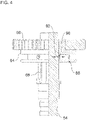
- Figur 4
- einen Halbschnittansicht einer Antriebswelle des beispielhaften Zwischengetriebes.
- Die in den Figuren gezeigten Ausführungsformen stimmen zumindest teilweise überein, so dass ähnliche oder identische Teile mit den gleichen Bezugszeichen versehen sind und zu deren Erläuterung auch auf die Beschreibung der anderen Ausführungsformen bzw. Figuren verwiesen wird, um Wiederholungen zu vermeiden.
- In
Figur 1 ist eine Vorrichtung 10 zum Lenken eines Kraftfahrzeugs dargestellt. Das Kraftfahrzeug kann insbesondere ein Nutzfahrzeug, zum Beispiel ein Omnibus oder ein Lastkraftwagen, sein. Die Vorrichtung 10 kann beispielsweise für einen Fahrschulbetrieb des Kraftfahrzeugs genutzt werden. - Die Vorrichtung 10 weist eine Hauptlenkeinrichtung 12, eine Zusatzlenkeinrichtung 14, ein Zwischengetriebe 16 und ein Lenkgetriebe 18 auf.
- Die Hauptlenkeinrichtung 12 dient als fahrerseitige Lenkeinrichtung des Kraftfahrzeugs. Die Hauptlenkeinrichtung 12 weist ein Lenkrad 20 und einen Lenkungsstrang 22 auf. Das Lenkrad 20 ist antreibend mit dem Lenkungsstrang 22 verbunden. Der Lenkungsstrang 22 ist antreibend mit dem Zwischengetriebe 16 verbunden. In der dargestellten Ausführungsform weist der Lenkungsstrang 22 eine Lenk-Gelenkwelle auf, die antreibend und gelenkig mit dem Zwischengetriebe 16 verbunden ist.
- Die Zusatzlenkeinrichtung 14 dient als beifahrerseitige Lenkeinrichtung des Kraftfahrzeugs. Die Zusatzlenkeinrichtung 14 weist ein Lenkrad 24 und einen Lenkungsstrang 26 auf. Das Lenkrad 24 ist antreibend mit dem Lenkungsstrang 26 verbunden. Der Lenkungsstrang 26 weist eine Mehrzahl von miteinander verbundenen Lenk-Gelenkwellen und Winkelgetrieben auf. Es ist allerdings beispielsweise auch möglich, den Lenkungsstrang 26 mit einer oder mehreren flexiblen Wellen vorzusehen.
- Im Einzelnen weist der Lenkungsstrang 26 eine erste Lenk-Gelenkwelle 28, eine Zwischenwelle 30, eine zweite Lenk-Gelenkwelle 32, ein erstes Winkelgetriebe 34, eine dritte Lenk-Gelenkwelle 36, ein zweites Winkelgetriebe 38 und eine vierte Lenk-Gelenkwelle 40 auf, die miteinander in der angegebenen Reihenfolge antreibend und jeweils gelenkig miteinander verbunden sind.
- Die Zwischenwelle 30 ist drehbar in einer Halterung 42 gelagert. Die Halterung 42 ist beispielsweise an einer Karosserie oder einem Rahmen des Kraftfahrzeugs befestigt. Das erste Winkelgetriebe 34 und das zweite Winkelgetriebe 38 können beispielsweise als Kegelradgetriebe ausgebildet sein. Das erste Winkelgetriebe 34 und das zweite Winkelgetriebe 38 dienen zur Umlenkung der übertragenen Drehung und des übertragenen Drehmoments um 90°. Das erste Winkelgetriebe 34 und das zweite Winkelgetriebe 38 können beispielsweise an einer Karosserie oder einem Rahmen des Kraftfahrzeugs befestigt sein. Die dritte Lenk-Gelenkwelle 36 erstreckt sich zwischen einer Beifahrerseite und einer Fahrerseite des Kraftfahrzeugs. Die vierte Lenk-Gelenkwelle 40 ist antreibend und gelenkig mit dem Zwischengetriebe 16 verbunden.
- Das Zwischengetriebe 16 ist antreibend mit dem Lenkgetriebe 18 verbunden. Das Zwischengetriebe 16 verbindet den Lenkungsstrang 22 trieblich mit dem Lenkgetriebe 18. Zusätzlich kann das Zwischengetriebe 16 den Lenkungsstrang 26 trieblich mit dem Lenkgetriebe 18 verbinden, wie hierin im Detail insbesondere unter Bezugnahme auf
Figur 3 beispielhaft beschrieben ist. - Das Lenkgetriebe 18 dient zum Wandeln einer Drehbewegung, die von dem Zwischengetriebe 16 eingeleitet wird, in einer ausgehende Schiebebewegung zum Lenken von Rädern des Kraftfahrzeugs. Das Lenkgetriebe 18 kann auf jegliche bekannte Art und Weise ausgebildet sein. Beispielsweise kann das Lenkgetriebe 18 als ein Kugelumlauflenkgetriebe ausgebildet sein. Es ist allerdings beispielsweise auch möglich, dass das Lenkgetriebe 18 als Zahnstangenlenkgetriebe, Schneckenlenkgetriebe oder Schraubenspindellenkgetriebe ausgebildet ist. Über eine Halterung 44 ist das Lenkgetriebe 18 beispielsweise an einem Rahmen oder einer Karosserie des Kraftfahrzeugs befestigt.
- Nachfolgend ist das beispielhafte Zwischengetriebe 16 im Detail insbesondere unter Bezugnahme auf die
Figuren 2 und3 beschrieben. DieFigur 2 zeigt das Zwischengetriebe 16 und das Lenkgetriebe 18 von außen. DieFigur 3 zeigt das Zwischengetriebe 16 ohne Gehäuse. - Das Zwischengetriebe 16 weist ein eigenes Gehäuse 46 auf. Das Gehäuse 46 kann beispielsweise aus zwei aneinander befestigten Gehäuseabschnitten, zum Beispiel Gehäusehälften, gebildet sein. Das Gehäuse 46 ist ein geschlossenes Gehäuse und nach innen sowie nach außen abgedichtet. Damit kann kein Schmutz in das Gehäuse 46 gelangen und kein Schmiermittel, zum Beispiel Schmierfett, aus dem Gehäuse 46 austreten.
- Das Gehäuse 46 ist direkt an einem Gehäuse 48 des Lenkgetriebes 18 befestigt. In dem dargestellten Ausführungsbeispiel ist das Gehäuse 46 über drei Schrauben 50 (nur zwei Schrauben in
Figur 2 sichtbar) an dem Gehäuse 48 befestigt. Die Befestigung erfolgt in einer definierten Ausrichtung, sodass eine einfache Montage und ein sicherer Betrieb gewährleistet sind. Dadurch dass die Gehäuse 46 und 48 aneinander befestigt sind, kommt es zu keinen Relativbewegungen zwischen dem Zwischengetriebe 16 und dem Lenkgetriebe 18. - Die Lenk-Gelenkwelle des Lenkungsstrangs 22 ist gelenkig und antreibend mit einem Wellenstumpf einer ersten Antriebswelle 52 des Zwischengetriebes 16 verbunden. Die Lenk-Gelenkwelle 40 ist gelenkig und antreibend mit einem Wellenstumpf einer zweiten Antriebswelle 54 des Zwischengetriebes 16 verbunden. Die Lenk-Gelenkwelle des Lenkungsstrangs 22 und die Lenk-Gelenkwelle 40 sind an entgegengesetzten Seiten des Zwischengetriebes 16 trieblich mit der jeweiligen Antriebswelle 52 und 54 verbunden. Die Wellenachsen der Antriebswellen 52 und 54 verlaufen im Wesentlichen parallel zueinander. Die Antriebswellen 52 und 54 sind drehbar im Gehäuse 46 des Zwischengetriebes 16 gelagert. Die ersten Antriebswelle 52 ist als eine Durchgangswelle ausgeführt, die über ein Abtriebselement 56 antreibend mit dem Lenkgetriebe 18 verbunden ist.
- Unter Bezugnahme auf
Figur 3 ist dargestellt, dass das Zwischengetriebe 16 als einstufiges Stirnradgetriebe ausgebildet ist. Ein angetriebenes Zahnrad 58 ist drehfest auf der ersten Antriebswelle 52 angeordnet. Ein treibendes Zahnrad 60 ist drehfest auf der zweiten Antriebswelle 54 angeordnet. Die Übersetzung zwischen dem treibenden Zahnrad 60 und dem angetriebenen Zahnrad 58 ist 1. - Das Zwischengetriebe 16 weist einen Kopplungsmechanismus 62 auf. Der Kopplungsmechanismus 62 ermöglicht eine Kopplung und Entkopplung der zweiten Antriebswelle 54 und der ersten Antriebswelle 52. In der entkoppelten Stellung des Kopplungsmechanismus 62 ist das Kraftfahrzeug mittels der Hauptlenkeinrichtung 12 (siehe
Figur 1 ) lenkbar. In der gekoppelten Stellung des Kopplungsmechanismus 62 ist das Kraftfahrzeug mittels der Hauptlenkeinrichtung 12 und der Zusatzlenkeinrichtung 14 (sieheFigur 1 ) lenkbar. - Im dargestellten Ausführungsbeispiel weist der Kopplungsmechanismus 62 eine Schiebemuffe 64 und eine Schaltgabel 66 auf. Die Schiebemuffe 64 ist drehfest und axial verschiebbar auf einem Keilwellenprofil 68 der zweiten Antriebswelle 54 angeordnet. Das treibende Zahnrad 60 ist drehfest mit der Schiebemuffe 64 verbunden. Beispielsweise können das treibende Zahnrad 60 und die Schiebemuffe 64 miteinander verschraubt sein. Mittels der Schaltgabel 66, die in eine Umfangsnut der Schiebemuffe 64 eingreift, kann die Schiebemuffe 64 auf dem Keilwellenprofil 68 zusammen mit dem treibenden Zahnrad 60 verschoben werden. Damit kann das treibende Zahnrad 60 wahlweise in Eingriff mit dem angetriebenen Zahnrad 58 und außer Eingriff von dem angetriebenen Zahnrad 58 verschoben werden. In
Figur 3 sind das treibende Zahnrad 60 und das angetriebene Zahnrad 58 in Eingriff miteinander. - Neben der hier dargestellten Ausführungsform des Kopplungsmechanismus 62 mit der Schiebemuffe 64 kann der Kopplungsmechanismus auch anders aufgebaut sein. Beispielsweise kann der Kopplungsmechanismus eine Kupplung, wie eine Klauenkupplung, aufweisen, die eine Triebverbindung zwischen dem treibenden Zahnrad 60 und der zweiten Antriebswelle 54 bilden kann. Hierbei ist es beispielsweise möglich, dass das treibende Zahnrad 60 nicht verschoben werden muss, sondern ständig im Eingriff mit dem angetriebenen Zahnrad 58 ist.
- Zum Betätigen des Kopplungsmechanismus 62 ist eine Betätigungseinrichtung 70 vorgesehen. Die Betätigungseinrichtung 70 weist eine Betätigungsstange 72, ein Griffstück 74 und ein Zwischenstück 76 auf. Die Betätigungsstange 72 ist mittels des Griffstücks 74 manuell verschiebbar. Das Griffstück 74 kann zum Verschieben der Betätigungsstange 72 beispielsweise bequem von einem Fahrersitz des Kraftfahrzeugs aus erreicht werden. Über das Zwischenstück 76 ist die Betätigungsstange 72 mit der Schaltgabel 66 verbunden, sodass eine Verschiebung der Betätigungsstange 72 eine Verschiebung der Schaltgabe 66 und somit eine Verschiebung der Schiebemuffe 72 und des treibenden Zahnrads 60 zur Folge hat. Beispielsweise kann ein Fahrer des Kraftfahrzeugs die Betätigungsstange 72 mittels des Griffstücks 74 nach oben ziehen, um den Kopplungsmechanismus 62 in die eingekoppelten Stellung zu verschieben.
- Um ein Verkanten der Schaltgabel 66 während einer Verschiebebewegung zu verhindern, ist die Betätigungseinrichtung 70 und damit der Kopplungsmechanismus 62 an einer Führungseinrichtung 78 längsgeführt. Die Führungseinrichtung 78 weist eine Führungsstange 80 und ein Durchgangsloch in dem Zwischenstück 76 auf. Die Führungsstange 80 ist in dem Gehäuse 46 des Zwischengetriebes 16 befestigt. Insbesondere ist die Betätigungseinrichtung 70 mittels des Durchgangslochs des Zwischenstücks 76 entlang der Führungsstange 80 längs verschiebbar.
- Das Zwischengetriebe 16 weist zudem eine Arretiereinrichtung 82 auf. Die Arretiereinrichtung 82 ermöglicht eine Arretierung des Kopplungsmechanismus 62 in der eingekoppelten Stellung und in der ausgekoppelten Stellung. Im Einzelnen kann ein Sicherungsstift (Sicherungsbolzen) 84 der Arretiereinrichtung 82 wahlweise in eines von zwei voneinander beabstandeten Durchgangslöchern in der Betätigungsstange 72 zum Arretieren der Betätigungsstange 72 eingeführt werden. In der arretierten Stellung kann die Betätigungseinrichtung 70 und somit der Kopplungsmechanismus 62 nicht verschoben werden. Beispielsweise kann der Sicherungsstift 84 mittels eines bequem vom Fahrersitz des Kraftfahrzeugs erreichbaren Griffstücks 86 gegriffen werden. Das Griffstück 86 ist an dem Sicherungsstift 84 befestigt.
- Wie in
Figur 2 gezeigt ist, sind die Griffstücke 74 und 86 außerhalb des Gehäuses 46 angeordnet und zugänglich. - In
Figur 4 ist eine Rasteinrichtung 88 gezeigt. Die Rasteinrichtung 88 ermöglicht, dass der Kopplungsmechanismus 62 in der eingekoppelten Stellung gehalten wird, sodass beim Lösen der Arretiereinrichtung 82 der Kopplungsmechanismus 62 sich nicht ohne gezielte Betätigung in die ausgekoppelte Stellung verschiebt. Stattdessen muss zur Überwindung der Rastwirkung der Rasteinrichtung 88 eine bestimmte Kraft mittels der Betätigungseinrichtung 70 aufgebracht werden, um den Kopplungsmechanismus 62 zu verschieben. Es ist beispielsweise auch möglich, dass eine alternative oder zusätzliche Rastvorrichtung vorgesehen ist, um den Kopplungsmechanismus 62 in der ausgekoppelten Stellung zu halten. - Im dargestellten Ausführungsbeispiel weist die Rasteinrichtung 88 mindestens einen federvorgespannten Rastkörper 90 auf, der verschiebbar in der Schiebemuffe 64 gelagert ist. Im Einzelnen ist der Rastkörper 90 in einer Richtung senkrecht zur Wellenachse der zweiten Antriebswelle 54 verschiebbar. In der eingekoppelten Stellung des Kopplungsmechanismus 62 greift der Rastkörper 90 in eine V-förmige Umfangsnut 92 des Keilwellenprofils 68 ein. Damit wird die Schiebemuffe 64 auf dem Keilwellenprofil 68 axial gesichert. Der Rastkörper 90 kann beispielsweise als eine Kugel ausgebildet sein oder zumindest einen Kugelkopf aufweisen. Unter Überwindung der Federvorspannung des Rastkörpers 90 kann die Schiebemuffe 64 in die ausgekoppelten Stellung des Kopplungsmechanismus 62 verschoben werden, wenn die Arretiereinrichtung 82 (siehe
Figur 3 ) gelöst ist. Es ist beispielsweise auch möglich, dass der Rastkörper federvorgespannt in der zweiten Antriebswelle 54 verschiebbar ist und die Umfangsnut an einer Innenumfangsfläche der Schiebemuffe 64 angeordnet ist. - Die Erfindung ist nicht auf die vorstehend beschriebenen bevorzugten Ausführungsbeispiele beschränkt. Vielmehr ist eine Vielzahl von Varianten und Abwandlungen möglich, die ebenfalls von dem Erfindungsgedanken Gebrauch machen und deshalb in den Schutzbereich fallen. Insbesondere beansprucht die Erfindung auch Schutz für den Gegenstand und die Merkmale der Unteransprüche unabhängig von den in Bezug genommenen Ansprüchen. Insbesondere sind die Merkmale des unabhängigen Anspruchs 1 unabhängig voneinander offenbart. Zusätzlich sind auch die Merkmale der Unteransprüche unabhängig von sämtlichen Merkmalen des unabhängigen Anspruchs 1 und beispielsweise unabhängig von den Merkmalen bezüglich des Vorhandenseins und/oder der Konfiguration der ersten Antriebswelle, der zweiten Antriebswelle und/oder des Kopplungsmechanismus des unabhängigen Anspruchs 1 offenbart.
-
- 10
- Vorrichtung zum Lenken
- 12
- Hauptlenkeinrichtung
- 14
- Zusatzlenkeinrichtung
- 16
- Zwischengetriebe
- 18
- Lenkgetriebe
- 20
- Lenkrad
- 22
- Lenkungsstrang
- 24
- Lenkrad
- 26
- Lenkungsstrang
- 28
- Lenk-Gelenkwelle
- 30
- Zwischenwelle
- 32
- Lenk-Gelenkwelle
- 34
- Winkelgetriebe
- 36
- Lenk-Gelenkwelle
- 38
- Winkelgetriebe
- 40
- Lenk-Gelenkwelle
- 42
- Halterung
- 44
- Halterung
- 46
- Gehäuse
- 48
- Gehäuse
- 50
- Schraube
- 52
- Erste Antriebswelle
- 54
- Zweite Antriebswelle
- 56
- Abtriebselement
- 58
- Angetriebenes Zahnrad
- 60
- Treibendes Zahnrad
- 62
- Kopplungsmechanismus
- 64
- Schiebemuffe
- 66
- Schaltgabel
- 68
- Keilwellenprofil
- 70
- Betätigungseinrichtung
- 72
- Betätigungsstange
- 74
- Griffstück
- 76
- Zwischenstück
- 78
- Führungseinrichtung
- 80
- Führungsstange
- 82
- Arretiereinrichtung
- 84
- Sicherungsstift
- 86
- Griffstück
- 88
- Rasteinrichtung
- 90
- Rastkörper
- 92
- Umfangsnut
Claims (14)
- Vorrichtung (10) zum Lenken eines Kraftfahrzeugs, insbesondere eines Nutzfahrzeugs, mit:einer fahrerseitigen Hauptlenkeinrichtung (12);einer beifahrerseitigen Zusatzlenkeinrichtung (14);einem Zwischengetriebe (16) aufweisend:- eine erste Antriebswelle (52), die trieblich mit einem Lenkungsstrang (22) der Hauptlenkeinrichtung (12) verbunden ist;- eine zweite Antriebswelle (54), die trieblich mit einem Lenkungsstrang (26) der Zusatzlenkeinrichtung (14) verbunden ist;- einen Kopplungsmechanismus (62), der zum wahlweisen Koppeln und Entkoppein der ersten Antriebswelle (52) und der zweiten Antriebswelle (54) ausgebildet ist; und- ein Gehäuse (46), in dem die erste Antriebswelle (52) und die zweite Antriebswelle (54) drehbar aufgenommen sind; undeiner Führungseinrichtung (78), mittels der der Kopplungsmechanismus (62) geführt ist.
- Vorrichtung (10) nach Anspruch 1, wobei:das Gehäuse (46) ein abgedichtetes und/oder geschlossenes Gehäuse ist; und/oderder Kopplungsmechanismus (62) in dem Gehäuse (46) aufgenommen ist.
- Vorrichtung (10) nach Anspruch 1 oder Anspruch 2, wobei:das Zwischengetriebe (16) als ein, insbesondere einstufiges, Stirnradgetriebe ausgebildet ist; und/oderdas Zwischengetriebe (16) eine Übersetzung von 1 aufweist; und/oderdie Zusatzlenkeinrichtung (14) und die Hauptlenkeinrichtung (12) an entgegengesetzten Seiten des Zwischengetriebes (16) trieblich mit dem Zwischengetriebe (16) verbindbar sind.
- Vorrichtung (10) nach einem der vorherigen Ansprüche, wobei:die erste Antriebswelle (52) drehfest mit einem angetriebenen Zahnrad (58) verbunden ist;die zweite Antriebswelle (54) drehfest mit einem treibenden Zahnrad (60) verbunden ist; undder Kopplungsmechanismus (62) zum wahlweisen Koppeln und Entkoppeln des treibenden Zahnrads (60) und des angetriebenen Zahnrads (58) ausgebildet ist.
- Vorrichtung (10) nach einem der vorherigen Ansprüche, wobei:
der Kopplungsmechanismus (62) eine Schiebemuffe (64) oder eine Kupplung, insbesondere eine Klauenkupplung, aufweist. - Vorrichtung (10) nach Anspruch 5, wobei:
das treibende Zahnrad (60) mit der Schiebemuffe (64) verschiebbar ist, um in Eingriff mit und außer Eingriff von dem angetriebenen Zahnrad (58) zu gelangen. - Vorrichtung (10) nach Anspruch 5 oder Anspruch 6, wobei:die Schiebemuffe (64) auf einem Keilwellenprofil (68) der zweiten Antriebswelle (54) verschiebbar ist; und/oderdie Schiebemuffe (64) mittels einer Schaltgabel (66) verschiebbar ist.
- Vorrichtung (10) nach einem der vorherigen Ansprüche, wobei:
die Führungseinrichtung (78) eine Führungsstange (80) aufweist und/oder der Kopplungsmechanismus (62) mittels der Führungseinrichtung (78) längsgeführt ist. - Vorrichtung (10) nach einem der vorherigen Ansprüche, ferner aufweisend:
eine Arretiereinrichtung (82), insbesondere aufweisend einen Sicherungsstift (84), mittels der der Kopplungsmechanismus (72) in einer eingekoppelten Stellung und/oder einer ausgekoppelten Stellung arretierbar ist. - Vorrichtung (10) nach einem der vorherigen Ansprüche, ferner aufweisend:
eine Rasteinrichtung (88), insbesondere aufweisend einen in eine Umfangsnut (92) einrastbaren federvorgespannten Rastkörper (90), mittels der der Kopplungsmechanismus (62) in einer eingekoppelten Stellung und/oder einer ausgekoppelten Stellung einrastbar ist. - Vorrichtung (10) nach einem der vorherigen Ansprüche, ferner aufweisend:
eine Betätigungseinrichtung (70), insbesondere aufweisend eine Betätigungsstange (72), mittels der der Kopplungsmechanismus (62) manuell betätigbar ist. - Vorrichtung (10) nach Anspruch 11, ferner aufweisend:
ein Lenkgetriebe (18), insbesondere zum Wandeln einer eingehenden Drehbewegung in eine ausgehende Schiebebewegung, wobei das Zwischengetriebe (16) antreibend mit dem Lenkgetriebe (18) verbunden ist. - Vorrichtung (10) nach Anspruch 12, wobei:
das Gehäuse (46) des Zwischengetriebes (16) und ein Gehäuse (48) des Lenkgetriebes (18) lösbar und/oder in einer definierten Ausrichtung zueinander aneinander befestigt sind. - Kraftfahrzeug, insbesondere Nutzfahrzeug, mit einer Vorrichtung (10) nach einem der vorherigen Ansprüche.
Applications Claiming Priority (1)
| Application Number | Priority Date | Filing Date | Title |
|---|---|---|---|
| ATA504/2017A AT520759B1 (de) | 2017-12-29 | 2017-12-29 | Vorrichtung zum Lenken eines Kraftfahrzeugs und Zwischengetriebe hierfür |
Publications (2)
| Publication Number | Publication Date |
|---|---|
| EP3508397A1 EP3508397A1 (de) | 2019-07-10 |
| EP3508397B1 true EP3508397B1 (de) | 2022-06-22 |
Family
ID=64572190
Family Applications (1)
| Application Number | Title | Priority Date | Filing Date |
|---|---|---|---|
| EP18209784.0A Active EP3508397B1 (de) | 2017-12-29 | 2018-12-03 | Vorrichtung zum lenken eines kraftfahrzeugs und zwischengetriebe hierfür |
Country Status (2)
| Country | Link |
|---|---|
| EP (1) | EP3508397B1 (de) |
| AT (1) | AT520759B1 (de) |
Cited By (1)
| Publication number | Priority date | Publication date | Assignee | Title |
|---|---|---|---|---|
| US20240278823A1 (en) * | 2023-02-16 | 2024-08-22 | Fontaine Modification Company | Assembly for equipping motor vehicle with dual-steer capabilities |
Families Citing this family (2)
| Publication number | Priority date | Publication date | Assignee | Title |
|---|---|---|---|---|
| CN114560008B (zh) * | 2020-11-27 | 2024-03-19 | 比亚迪股份有限公司 | 转向系统和车辆 |
| DE102024102727A1 (de) * | 2024-01-31 | 2025-07-31 | Bayerische Motoren Werke Aktiengesellschaft | Simulationssteuerung in einem Kraftfahrzeug |
Family Cites Families (6)
| Publication number | Priority date | Publication date | Assignee | Title |
|---|---|---|---|---|
| GB204340A (en) * | 1922-09-23 | 1924-02-28 | Joan Dimitriu | Improvements in or relating to steering and controlling devices for power-driven vehicles for instruction purposes |
| DE1530548A1 (de) * | 1965-03-10 | 1969-06-19 | Daimler Benz Ag | Mehrradlenkung fuer Kraftfahrzeuge |
| JPS57139473U (de) * | 1981-02-27 | 1982-08-31 | ||
| CN201984662U (zh) * | 2011-03-14 | 2011-09-21 | 安徽江淮客车有限公司 | 一种教练车转向传动装置 |
| CN106218703B (zh) * | 2016-09-12 | 2018-11-06 | 北京汽车股份有限公司 | 教练车、教练车转向系统及其控制方法 |
| AT518994B1 (de) * | 2016-10-25 | 2018-03-15 | MAN TRUCK & BUS OESTERREICH GesmbH | Lenksystem für ein Kraftfahrzeug, vorzugsweise Fahrschul-Kraftfahrzeug |
-
2017
- 2017-12-29 AT ATA504/2017A patent/AT520759B1/de active
-
2018
- 2018-12-03 EP EP18209784.0A patent/EP3508397B1/de active Active
Cited By (2)
| Publication number | Priority date | Publication date | Assignee | Title |
|---|---|---|---|---|
| US20240278823A1 (en) * | 2023-02-16 | 2024-08-22 | Fontaine Modification Company | Assembly for equipping motor vehicle with dual-steer capabilities |
| US12434758B2 (en) * | 2023-02-16 | 2025-10-07 | Fontaine Modification Company | Assembly for equipping motor vehicle with dual-steer capabilities |
Also Published As
| Publication number | Publication date |
|---|---|
| AT520759B1 (de) | 2019-10-15 |
| EP3508397A1 (de) | 2019-07-10 |
| AT520759A1 (de) | 2019-07-15 |
Similar Documents
| Publication | Publication Date | Title |
|---|---|---|
| DE10162337B4 (de) | Längs eingebauter Antriebsstrang | |
| DE3334905A1 (de) | Kraftwagen mit vierradantrieb | |
| EP2616264B1 (de) | Verteilergetriebe | |
| EP3508397B1 (de) | Vorrichtung zum lenken eines kraftfahrzeugs und zwischengetriebe hierfür | |
| EP3707024B1 (de) | Modularer antriebsstrang sowie ein fahrzeug mit einem solchen antriebsstrang | |
| DE102016204560A1 (de) | Lenksystem für ein lenkbares Fahrzeug | |
| DE3873440T2 (de) | Fahrzeug fuer gartenarbeiten sowie landwirtschaftliche arbeiten. | |
| DE1430831A1 (de) | Mehrrad-,insbesondere Vierradantriebseinheit | |
| DE102019000035A1 (de) | Lenkeinrichtung für ein autonom betreibbares Kraftfahrzeug sowie Verfahren zum Betreiben einer Lenkeinrichtung | |
| EP3315382B1 (de) | Lenksystem für ein kraftfahrzeug, vorzugsweise ein fahrschul-kraftfahrzeug | |
| DE2605674C2 (de) | Getriebeanordnung für Dreiachs- Kraftfahrzeuge mit Allradantrieb | |
| DE102013222086A1 (de) | Antriebsstrang für ein Schienenfahrzeug | |
| DE112008003397T5 (de) | Lenkvorrichtung | |
| DE1555953C3 (de) | Antriebseinrichtung für wahlweise In Zwei-Rad- oder Vier-Rad-Antrieb zu schaltende Kraftfahrzeuge, insbesondere Mähdrescher | |
| DE69814989T2 (de) | Geländefahrzeug mit lenkbarer Vorderachse und Frontzapfwellenkupplung | |
| DE69009565T2 (de) | Differentialgetriebe. | |
| DE102008009060B4 (de) | Elektrische Servolenkung mit angetriebener Lenkwelle | |
| DE3920934A1 (de) | Anhaengereigene antriebseinrichtung | |
| DE102022001304A1 (de) | Differentialgetriebe und Antriebsstrang mit einem solchen Differentialgetriebe | |
| EP3348454B1 (de) | Getriebe für ein rad- und/oder kettenfahrzeug | |
| EP2671738A2 (de) | Betätigungssystem für eine Anhängekupplung eines Kraftfahrzeugs | |
| DE102015220776A1 (de) | Radaufhängung für ein lenkbares Fahrzeugrad eines Kraftfahrzeuges | |
| DE102022119195B4 (de) | Getriebe, Kraftfahrzeug und Verfahren zum Betreiben eines entsprechenden Getriebes | |
| DE102008031204B4 (de) | Lenkeinrichtung für ein Radfahrzeug mit Achsschenkellenkung | |
| DE102018219600B4 (de) | Dämpfungseinrichtung für einen Antriebsstrang eines Kraftfahrzeugs, Antriebsstrang für ein Kraftfahrzeug, sowie Kraftfahrzeug |
Legal Events
| Date | Code | Title | Description |
|---|---|---|---|
| PUAI | Public reference made under article 153(3) epc to a published international application that has entered the european phase |
Free format text: ORIGINAL CODE: 0009012 |
|
| STAA | Information on the status of an ep patent application or granted ep patent |
Free format text: STATUS: THE APPLICATION HAS BEEN PUBLISHED |
|
| AK | Designated contracting states |
Kind code of ref document: A1 Designated state(s): AL AT BE BG CH CY CZ DE DK EE ES FI FR GB GR HR HU IE IS IT LI LT LU LV MC MK MT NL NO PL PT RO RS SE SI SK SM TR |
|
| AX | Request for extension of the european patent |
Extension state: BA ME |
|
| STAA | Information on the status of an ep patent application or granted ep patent |
Free format text: STATUS: REQUEST FOR EXAMINATION WAS MADE |
|
| 17P | Request for examination filed |
Effective date: 20200109 |
|
| RBV | Designated contracting states (corrected) |
Designated state(s): AL AT BE BG CH CY CZ DE DK EE ES FI FR GB GR HR HU IE IS IT LI LT LU LV MC MK MT NL NO PL PT RO RS SE SI SK SM TR |
|
| STAA | Information on the status of an ep patent application or granted ep patent |
Free format text: STATUS: EXAMINATION IS IN PROGRESS |
|
| 17Q | First examination report despatched |
Effective date: 20201218 |
|
| RAP1 | Party data changed (applicant data changed or rights of an application transferred) |
Owner name: MAN TRUCK & BUS SE |
|
| GRAP | Despatch of communication of intention to grant a patent |
Free format text: ORIGINAL CODE: EPIDOSNIGR1 |
|
| STAA | Information on the status of an ep patent application or granted ep patent |
Free format text: STATUS: GRANT OF PATENT IS INTENDED |
|
| INTG | Intention to grant announced |
Effective date: 20220117 |
|
| GRAS | Grant fee paid |
Free format text: ORIGINAL CODE: EPIDOSNIGR3 |
|
| GRAA | (expected) grant |
Free format text: ORIGINAL CODE: 0009210 |
|
| STAA | Information on the status of an ep patent application or granted ep patent |
Free format text: STATUS: THE PATENT HAS BEEN GRANTED |
|
| AK | Designated contracting states |
Kind code of ref document: B1 Designated state(s): AL AT BE BG CH CY CZ DE DK EE ES FI FR GB GR HR HU IE IS IT LI LT LU LV MC MK MT NL NO PL PT RO RS SE SI SK SM TR |
|
| REG | Reference to a national code |
Ref country code: GB Ref legal event code: FG4D Free format text: NOT ENGLISH |
|
| REG | Reference to a national code |
Ref country code: CH Ref legal event code: EP |
|
| REG | Reference to a national code |
Ref country code: DE Ref legal event code: R096 Ref document number: 502018009970 Country of ref document: DE |
|
| REG | Reference to a national code |
Ref country code: AT Ref legal event code: REF Ref document number: 1499613 Country of ref document: AT Kind code of ref document: T Effective date: 20220715 |
|
| REG | Reference to a national code |
Ref country code: IE Ref legal event code: FG4D Free format text: LANGUAGE OF EP DOCUMENT: GERMAN |
|
| REG | Reference to a national code |
Ref country code: NL Ref legal event code: FP |
|
| REG | Reference to a national code |
Ref country code: SE Ref legal event code: TRGR |
|
| REG | Reference to a national code |
Ref country code: LT Ref legal event code: MG9D |
|
| PG25 | Lapsed in a contracting state [announced via postgrant information from national office to epo] |
Ref country code: NO Free format text: LAPSE BECAUSE OF FAILURE TO SUBMIT A TRANSLATION OF THE DESCRIPTION OR TO PAY THE FEE WITHIN THE PRESCRIBED TIME-LIMIT Effective date: 20220922 Ref country code: LT Free format text: LAPSE BECAUSE OF FAILURE TO SUBMIT A TRANSLATION OF THE DESCRIPTION OR TO PAY THE FEE WITHIN THE PRESCRIBED TIME-LIMIT Effective date: 20220622 Ref country code: HR Free format text: LAPSE BECAUSE OF FAILURE TO SUBMIT A TRANSLATION OF THE DESCRIPTION OR TO PAY THE FEE WITHIN THE PRESCRIBED TIME-LIMIT Effective date: 20220622 Ref country code: GR Free format text: LAPSE BECAUSE OF FAILURE TO SUBMIT A TRANSLATION OF THE DESCRIPTION OR TO PAY THE FEE WITHIN THE PRESCRIBED TIME-LIMIT Effective date: 20220923 Ref country code: FI Free format text: LAPSE BECAUSE OF FAILURE TO SUBMIT A TRANSLATION OF THE DESCRIPTION OR TO PAY THE FEE WITHIN THE PRESCRIBED TIME-LIMIT Effective date: 20220622 Ref country code: BG Free format text: LAPSE BECAUSE OF FAILURE TO SUBMIT A TRANSLATION OF THE DESCRIPTION OR TO PAY THE FEE WITHIN THE PRESCRIBED TIME-LIMIT Effective date: 20220922 |
|
| PG25 | Lapsed in a contracting state [announced via postgrant information from national office to epo] |
Ref country code: RS Free format text: LAPSE BECAUSE OF FAILURE TO SUBMIT A TRANSLATION OF THE DESCRIPTION OR TO PAY THE FEE WITHIN THE PRESCRIBED TIME-LIMIT Effective date: 20220622 Ref country code: LV Free format text: LAPSE BECAUSE OF FAILURE TO SUBMIT A TRANSLATION OF THE DESCRIPTION OR TO PAY THE FEE WITHIN THE PRESCRIBED TIME-LIMIT Effective date: 20220622 |
|
| PG25 | Lapsed in a contracting state [announced via postgrant information from national office to epo] |
Ref country code: SM Free format text: LAPSE BECAUSE OF FAILURE TO SUBMIT A TRANSLATION OF THE DESCRIPTION OR TO PAY THE FEE WITHIN THE PRESCRIBED TIME-LIMIT Effective date: 20220622 Ref country code: SK Free format text: LAPSE BECAUSE OF FAILURE TO SUBMIT A TRANSLATION OF THE DESCRIPTION OR TO PAY THE FEE WITHIN THE PRESCRIBED TIME-LIMIT Effective date: 20220622 Ref country code: RO Free format text: LAPSE BECAUSE OF FAILURE TO SUBMIT A TRANSLATION OF THE DESCRIPTION OR TO PAY THE FEE WITHIN THE PRESCRIBED TIME-LIMIT Effective date: 20220622 Ref country code: PT Free format text: LAPSE BECAUSE OF FAILURE TO SUBMIT A TRANSLATION OF THE DESCRIPTION OR TO PAY THE FEE WITHIN THE PRESCRIBED TIME-LIMIT Effective date: 20221024 Ref country code: ES Free format text: LAPSE BECAUSE OF FAILURE TO SUBMIT A TRANSLATION OF THE DESCRIPTION OR TO PAY THE FEE WITHIN THE PRESCRIBED TIME-LIMIT Effective date: 20220622 Ref country code: EE Free format text: LAPSE BECAUSE OF FAILURE TO SUBMIT A TRANSLATION OF THE DESCRIPTION OR TO PAY THE FEE WITHIN THE PRESCRIBED TIME-LIMIT Effective date: 20220622 Ref country code: CZ Free format text: LAPSE BECAUSE OF FAILURE TO SUBMIT A TRANSLATION OF THE DESCRIPTION OR TO PAY THE FEE WITHIN THE PRESCRIBED TIME-LIMIT Effective date: 20220622 |
|
| PG25 | Lapsed in a contracting state [announced via postgrant information from national office to epo] |
Ref country code: PL Free format text: LAPSE BECAUSE OF FAILURE TO SUBMIT A TRANSLATION OF THE DESCRIPTION OR TO PAY THE FEE WITHIN THE PRESCRIBED TIME-LIMIT Effective date: 20220622 Ref country code: IS Free format text: LAPSE BECAUSE OF FAILURE TO SUBMIT A TRANSLATION OF THE DESCRIPTION OR TO PAY THE FEE WITHIN THE PRESCRIBED TIME-LIMIT Effective date: 20221022 |
|
| REG | Reference to a national code |
Ref country code: DE Ref legal event code: R097 Ref document number: 502018009970 Country of ref document: DE |
|
| PG25 | Lapsed in a contracting state [announced via postgrant information from national office to epo] |
Ref country code: AL Free format text: LAPSE BECAUSE OF FAILURE TO SUBMIT A TRANSLATION OF THE DESCRIPTION OR TO PAY THE FEE WITHIN THE PRESCRIBED TIME-LIMIT Effective date: 20220622 |
|
| PG25 | Lapsed in a contracting state [announced via postgrant information from national office to epo] |
Ref country code: DK Free format text: LAPSE BECAUSE OF FAILURE TO SUBMIT A TRANSLATION OF THE DESCRIPTION OR TO PAY THE FEE WITHIN THE PRESCRIBED TIME-LIMIT Effective date: 20220622 |
|
| PLBE | No opposition filed within time limit |
Free format text: ORIGINAL CODE: 0009261 |
|
| STAA | Information on the status of an ep patent application or granted ep patent |
Free format text: STATUS: NO OPPOSITION FILED WITHIN TIME LIMIT |
|
| 26N | No opposition filed |
Effective date: 20230323 |
|
| REG | Reference to a national code |
Ref country code: CH Ref legal event code: PL |
|
| GBPC | Gb: european patent ceased through non-payment of renewal fee |
Effective date: 20221203 |
|
| REG | Reference to a national code |
Ref country code: BE Ref legal event code: MM Effective date: 20221231 |
|
| PG25 | Lapsed in a contracting state [announced via postgrant information from national office to epo] |
Ref country code: SI Free format text: LAPSE BECAUSE OF FAILURE TO SUBMIT A TRANSLATION OF THE DESCRIPTION OR TO PAY THE FEE WITHIN THE PRESCRIBED TIME-LIMIT Effective date: 20220622 Ref country code: LU Free format text: LAPSE BECAUSE OF NON-PAYMENT OF DUE FEES Effective date: 20221203 |
|
| PG25 | Lapsed in a contracting state [announced via postgrant information from national office to epo] |
Ref country code: LI Free format text: LAPSE BECAUSE OF NON-PAYMENT OF DUE FEES Effective date: 20221231 Ref country code: IE Free format text: LAPSE BECAUSE OF NON-PAYMENT OF DUE FEES Effective date: 20221203 Ref country code: GB Free format text: LAPSE BECAUSE OF NON-PAYMENT OF DUE FEES Effective date: 20221203 Ref country code: CH Free format text: LAPSE BECAUSE OF NON-PAYMENT OF DUE FEES Effective date: 20221231 |
|
| PG25 | Lapsed in a contracting state [announced via postgrant information from national office to epo] |
Ref country code: BE Free format text: LAPSE BECAUSE OF NON-PAYMENT OF DUE FEES Effective date: 20221231 |
|
| PG25 | Lapsed in a contracting state [announced via postgrant information from national office to epo] |
Ref country code: HU Free format text: LAPSE BECAUSE OF FAILURE TO SUBMIT A TRANSLATION OF THE DESCRIPTION OR TO PAY THE FEE WITHIN THE PRESCRIBED TIME-LIMIT; INVALID AB INITIO Effective date: 20181203 |
|
| PG25 | Lapsed in a contracting state [announced via postgrant information from national office to epo] |
Ref country code: CY Free format text: LAPSE BECAUSE OF FAILURE TO SUBMIT A TRANSLATION OF THE DESCRIPTION OR TO PAY THE FEE WITHIN THE PRESCRIBED TIME-LIMIT Effective date: 20220622 |
|
| PG25 | Lapsed in a contracting state [announced via postgrant information from national office to epo] |
Ref country code: MK Free format text: LAPSE BECAUSE OF FAILURE TO SUBMIT A TRANSLATION OF THE DESCRIPTION OR TO PAY THE FEE WITHIN THE PRESCRIBED TIME-LIMIT Effective date: 20220622 |
|
| PG25 | Lapsed in a contracting state [announced via postgrant information from national office to epo] |
Ref country code: MC Free format text: LAPSE BECAUSE OF FAILURE TO SUBMIT A TRANSLATION OF THE DESCRIPTION OR TO PAY THE FEE WITHIN THE PRESCRIBED TIME-LIMIT Effective date: 20220622 |
|
| PG25 | Lapsed in a contracting state [announced via postgrant information from national office to epo] |
Ref country code: MC Free format text: LAPSE BECAUSE OF FAILURE TO SUBMIT A TRANSLATION OF THE DESCRIPTION OR TO PAY THE FEE WITHIN THE PRESCRIBED TIME-LIMIT Effective date: 20220622 |
|
| PG25 | Lapsed in a contracting state [announced via postgrant information from national office to epo] |
Ref country code: MT Free format text: LAPSE BECAUSE OF FAILURE TO SUBMIT A TRANSLATION OF THE DESCRIPTION OR TO PAY THE FEE WITHIN THE PRESCRIBED TIME-LIMIT Effective date: 20220622 |
|
| PG25 | Lapsed in a contracting state [announced via postgrant information from national office to epo] |
Ref country code: BG Free format text: LAPSE BECAUSE OF FAILURE TO SUBMIT A TRANSLATION OF THE DESCRIPTION OR TO PAY THE FEE WITHIN THE PRESCRIBED TIME-LIMIT Effective date: 20220622 |
|
| PG25 | Lapsed in a contracting state [announced via postgrant information from national office to epo] |
Ref country code: BG Free format text: LAPSE BECAUSE OF FAILURE TO SUBMIT A TRANSLATION OF THE DESCRIPTION OR TO PAY THE FEE WITHIN THE PRESCRIBED TIME-LIMIT Effective date: 20220622 |
|
| REG | Reference to a national code |
Ref country code: AT Ref legal event code: MM01 Ref document number: 1499613 Country of ref document: AT Kind code of ref document: T Effective date: 20231203 |
|
| PG25 | Lapsed in a contracting state [announced via postgrant information from national office to epo] |
Ref country code: AT Free format text: LAPSE BECAUSE OF NON-PAYMENT OF DUE FEES Effective date: 20231203 |
|
| PG25 | Lapsed in a contracting state [announced via postgrant information from national office to epo] |
Ref country code: TR Free format text: LAPSE BECAUSE OF FAILURE TO SUBMIT A TRANSLATION OF THE DESCRIPTION OR TO PAY THE FEE WITHIN THE PRESCRIBED TIME-LIMIT Effective date: 20220622 |
|
| PGFP | Annual fee paid to national office [announced via postgrant information from national office to epo] |
Ref country code: IT Payment date: 20251218 Year of fee payment: 8 |
|
| PGFP | Annual fee paid to national office [announced via postgrant information from national office to epo] |
Ref country code: FR Payment date: 20251230 Year of fee payment: 8 Ref country code: NL Payment date: 20251222 Year of fee payment: 8 |
|
| PGFP | Annual fee paid to national office [announced via postgrant information from national office to epo] |
Ref country code: SE Payment date: 20251222 Year of fee payment: 8 |
|
| PGFP | Annual fee paid to national office [announced via postgrant information from national office to epo] |
Ref country code: DE Payment date: 20251229 Year of fee payment: 8 |
|
| PGFP | Annual fee paid to national office [announced via postgrant information from national office to epo] |
Ref country code: AT Payment date: 20260410 Year of fee payment: 5 |