EP3509280B1 - Wasserdichte anzeigevorrichtung oder tragbares endgerät - Google Patents
Wasserdichte anzeigevorrichtung oder tragbares endgerät Download PDFInfo
- Publication number
- EP3509280B1 EP3509280B1 EP19150505.6A EP19150505A EP3509280B1 EP 3509280 B1 EP3509280 B1 EP 3509280B1 EP 19150505 A EP19150505 A EP 19150505A EP 3509280 B1 EP3509280 B1 EP 3509280B1
- Authority
- EP
- European Patent Office
- Prior art keywords
- sealing member
- display panel
- display device
- portable terminal
- disposed
- Prior art date
- Legal status (The legal status is an assumption and is not a legal conclusion. Google has not performed a legal analysis and makes no representation as to the accuracy of the status listed.)
- Active
Links
Images




Classifications
-
- H—ELECTRICITY
- H04—ELECTRIC COMMUNICATION TECHNIQUE
- H04M—TELEPHONIC COMMUNICATION
- H04M1/00—Substation equipment, e.g. for use by subscribers
- H04M1/02—Constructional features of telephone sets
- H04M1/0202—Portable telephone sets, e.g. cordless phones, mobile phones or bar type handsets
- H04M1/026—Details of the structure or mounting of specific components
- H04M1/0266—Details of the structure or mounting of specific components for a display module assembly
- H04M1/0268—Details of the structure or mounting of specific components for a display module assembly including a flexible display panel
- H04M1/0269—Details of the structure or mounting of specific components for a display module assembly including a flexible display panel mounted in a fixed curved configuration, e.g. display curved around the edges of the telephone housing
-
- G—PHYSICS
- G06—COMPUTING OR CALCULATING; COUNTING
- G06F—ELECTRIC DIGITAL DATA PROCESSING
- G06F3/00—Input arrangements for transferring data to be processed into a form capable of being handled by the computer; Output arrangements for transferring data from processing unit to output unit, e.g. interface arrangements
- G06F3/01—Input arrangements or combined input and output arrangements for interaction between user and computer
- G06F3/03—Arrangements for converting the position or the displacement of a member into a coded form
- G06F3/041—Digitisers, e.g. for touch screens or touch pads, characterised by the transducing means
- G06F3/0412—Digitisers structurally integrated in a display
-
- H—ELECTRICITY
- H04—ELECTRIC COMMUNICATION TECHNIQUE
- H04M—TELEPHONIC COMMUNICATION
- H04M1/00—Substation equipment, e.g. for use by subscribers
- H04M1/02—Constructional features of telephone sets
- H04M1/0202—Portable telephone sets, e.g. cordless phones, mobile phones or bar type handsets
- H04M1/026—Details of the structure or mounting of specific components
- H04M1/0266—Details of the structure or mounting of specific components for a display module assembly
-
- G—PHYSICS
- G09—EDUCATION; CRYPTOGRAPHY; DISPLAY; ADVERTISING; SEALS
- G09F—DISPLAYING; ADVERTISING; SIGNS; LABELS OR NAME-PLATES; SEALS
- G09F9/00—Indicating arrangements for variable information in which the information is built-up on a support by selection or combination of individual elements
-
- H—ELECTRICITY
- H04—ELECTRIC COMMUNICATION TECHNIQUE
- H04M—TELEPHONIC COMMUNICATION
- H04M1/00—Substation equipment, e.g. for use by subscribers
- H04M1/02—Constructional features of telephone sets
- H04M1/0202—Portable telephone sets, e.g. cordless phones, mobile phones or bar type handsets
-
- H—ELECTRICITY
- H04—ELECTRIC COMMUNICATION TECHNIQUE
- H04M—TELEPHONIC COMMUNICATION
- H04M1/00—Substation equipment, e.g. for use by subscribers
- H04M1/02—Constructional features of telephone sets
- H04M1/0202—Portable telephone sets, e.g. cordless phones, mobile phones or bar type handsets
- H04M1/026—Details of the structure or mounting of specific components
- H04M1/0277—Details of the structure or mounting of specific components for a printed circuit board assembly
-
- H—ELECTRICITY
- H04—ELECTRIC COMMUNICATION TECHNIQUE
- H04M—TELEPHONIC COMMUNICATION
- H04M1/00—Substation equipment, e.g. for use by subscribers
- H04M1/02—Constructional features of telephone sets
- H04M1/18—Telephone sets specially adapted for use in ships, mines, or other places exposed to adverse environment
-
- H—ELECTRICITY
- H05—ELECTRIC TECHNIQUES NOT OTHERWISE PROVIDED FOR
- H05K—PRINTED CIRCUITS; CASINGS OR CONSTRUCTIONAL DETAILS OF ELECTRIC APPARATUS; MANUFACTURE OF ASSEMBLAGES OF ELECTRICAL COMPONENTS
- H05K1/00—Printed circuits
- H05K1/18—Printed circuits structurally associated with non-printed electric components
- H05K1/189—Printed circuits structurally associated with non-printed electric components characterised by the use of flexible or folded printed circuits
-
- H—ELECTRICITY
- H05—ELECTRIC TECHNIQUES NOT OTHERWISE PROVIDED FOR
- H05K—PRINTED CIRCUITS; CASINGS OR CONSTRUCTIONAL DETAILS OF ELECTRIC APPARATUS; MANUFACTURE OF ASSEMBLAGES OF ELECTRICAL COMPONENTS
- H05K5/00—Casings, cabinets or drawers for electric apparatus
- H05K5/0086—Casings, cabinets or drawers for electric apparatus portable, e.g. battery operated apparatus
-
- H—ELECTRICITY
- H05—ELECTRIC TECHNIQUES NOT OTHERWISE PROVIDED FOR
- H05K—PRINTED CIRCUITS; CASINGS OR CONSTRUCTIONAL DETAILS OF ELECTRIC APPARATUS; MANUFACTURE OF ASSEMBLAGES OF ELECTRICAL COMPONENTS
- H05K5/00—Casings, cabinets or drawers for electric apparatus
- H05K5/06—Hermetically-sealed casings
- H05K5/062—Hermetically-sealed casings sealed by a material injected between a non-removable cover and a body, e.g. hardening in situ
-
- H—ELECTRICITY
- H05—ELECTRIC TECHNIQUES NOT OTHERWISE PROVIDED FOR
- H05K—PRINTED CIRCUITS; CASINGS OR CONSTRUCTIONAL DETAILS OF ELECTRIC APPARATUS; MANUFACTURE OF ASSEMBLAGES OF ELECTRICAL COMPONENTS
- H05K5/00—Casings, cabinets or drawers for electric apparatus
- H05K5/06—Hermetically-sealed casings
- H05K5/065—Hermetically-sealed casings sealed by encapsulation, e.g. waterproof resin forming an integral casing, injection moulding
-
- H—ELECTRICITY
- H10—SEMICONDUCTOR DEVICES; ELECTRIC SOLID-STATE DEVICES NOT OTHERWISE PROVIDED FOR
- H10K—ORGANIC ELECTRIC SOLID-STATE DEVICES
- H10K50/00—Organic light-emitting devices
- H10K50/80—Constructional details
- H10K50/84—Passivation; Containers; Encapsulations
- H10K50/842—Containers
- H10K50/8426—Peripheral sealing arrangements, e.g. adhesives, sealants
-
- H—ELECTRICITY
- H10—SEMICONDUCTOR DEVICES; ELECTRIC SOLID-STATE DEVICES NOT OTHERWISE PROVIDED FOR
- H10K—ORGANIC ELECTRIC SOLID-STATE DEVICES
- H10K77/00—Constructional details of devices covered by this subclass and not covered by groups H10K10/80, H10K30/80, H10K50/80 or H10K59/80
- H10K77/10—Substrates, e.g. flexible substrates
- H10K77/111—Flexible substrates
-
- H—ELECTRICITY
- H04—ELECTRIC COMMUNICATION TECHNIQUE
- H04M—TELEPHONIC COMMUNICATION
- H04M2201/00—Electronic components, circuits, software, systems or apparatus used in telephone systems
- H04M2201/38—Displays
-
- H—ELECTRICITY
- H05—ELECTRIC TECHNIQUES NOT OTHERWISE PROVIDED FOR
- H05K—PRINTED CIRCUITS; CASINGS OR CONSTRUCTIONAL DETAILS OF ELECTRIC APPARATUS; MANUFACTURE OF ASSEMBLAGES OF ELECTRICAL COMPONENTS
- H05K2201/00—Indexing scheme relating to printed circuits covered by H05K1/00
- H05K2201/10—Details of components or other objects attached to or integrated in a printed circuit board
- H05K2201/10007—Types of components
- H05K2201/10128—Display
-
- H—ELECTRICITY
- H10—SEMICONDUCTOR DEVICES; ELECTRIC SOLID-STATE DEVICES NOT OTHERWISE PROVIDED FOR
- H10K—ORGANIC ELECTRIC SOLID-STATE DEVICES
- H10K59/00—Integrated devices, or assemblies of multiple devices, comprising at least one organic light-emitting element covered by group H10K50/00
- H10K59/80—Constructional details
- H10K59/87—Passivation; Containers; Encapsulations
- H10K59/873—Encapsulations
-
- Y—GENERAL TAGGING OF NEW TECHNOLOGICAL DEVELOPMENTS; GENERAL TAGGING OF CROSS-SECTIONAL TECHNOLOGIES SPANNING OVER SEVERAL SECTIONS OF THE IPC; TECHNICAL SUBJECTS COVERED BY FORMER USPC CROSS-REFERENCE ART COLLECTIONS [XRACs] AND DIGESTS
- Y02—TECHNOLOGIES OR APPLICATIONS FOR MITIGATION OR ADAPTATION AGAINST CLIMATE CHANGE
- Y02E—REDUCTION OF GREENHOUSE GAS [GHG] EMISSIONS, RELATED TO ENERGY GENERATION, TRANSMISSION OR DISTRIBUTION
- Y02E10/00—Energy generation through renewable energy sources
- Y02E10/50—Photovoltaic [PV] energy
- Y02E10/549—Organic PV cells
Definitions
- the present disclosure relates to a display device and, more particularly, to a waterproof display device and a portable terminal.
- Portable terminals are small electronic devices that can be easily carried by a user and may be configured to perform various functions. Examples of portable terminals include smartphones, point-of-sale devices, and various specialized electronic tools used by people. Portable terminals often include display devices for displaying information and images to the user. Users frequently use portable terminals in various environments, and thus portable terminals may be made waterproof to prevent damage that may otherwise be caused by exposure to liquids.
- portable terminals may have curved surfaces for reasons of appearance and/or convenience.
- a curved portable terminal may include a display panel of which at least a portion is curved, and various components coupled to the display panel. Since the display panel is curved, water may more easily permeate into the curved portable terminal through a curved area, in which internal components of the portable terminal may be disposed more closely to an outer surface of the portable terminal.
- the present invention can be used in connection with a display device or portable terminal that includes a window member having at least one flat portion and at least one bent portion. Therefore, the present disclosure and especially the features of the different examples described herein can be used for both, a display device and a portable terminal.
- FIG. 1 is a perspective view illustrating a display device according to exemplary embodiments of the present invention
- FIG. 2 is an exploded perspective view illustrating the display device of FIG. 1 .
- a portable terminal including a display device is illustrated as an exemplary embodiment of the present invention.
- the portable terminal may be a tablet personal computer (tablet PC), a smart phone, a personal digital assistant (PDA), a portable multimedia player (PMP), a game console, or a watch-type electronic device.
- PDA personal digital assistant
- PMP portable multimedia player
- game console or a watch-type electronic device.
- embodiments of the invention are not limited thereto.
- the display device may be applied to large-sized electronic devices (e.g., televisions and/or electronic billboards) and small and middle-sized electronic devices (e.g., personal computers, notebook computers, car navigation units, and/or cameras).
- these are provided only as examples of the invention, and the terminal including the display device, according to the invention, may also be applied to other electronic devices.
- the display device/portable terminal 1000 may include a plurality of areas divided from each other in a display surface.
- the display device 1000 may include a display area AR in which an image IM is displayed, and a non-display area BR adjacent to the display area AR.
- the display area AR may have a quadrilateral shape (e.g., a rectangular shape) when viewed in a plan view.
- the non-display area BR may at least partially surround the display area AR, for example, the non-display area BR may surround the display area AR on a top side and a bottom side.
- the display device 1000 may have a shape which is partially bent.
- the display device 1000 may include a flat portion FA, which is substantially flat, and bent portions BA1 and BA2 , which are substantially bent, which are each connected to the flat portion FA.
- the flat portion FA may lie parallel to a plane defined by a first direction DR1 and a second direction DR2.
- a normal direction of the flat portion FA may be indicated by a third direction DR3.
- the third direction DR3 may be a reference direction for defining a front surface and a rear surface of each member of the display device 1000.
- the directions may be relative concepts and may be alternatively contemplated.
- the bent portions BA1 and BA2 may include a first bent portion BA1 and a second bent portion BA2.
- the first bent portion BA1 and the second bent portion BA2 may be opposite to each other in the first direction DR1 with the flat portion FA interposed therebetween.
- the first bent portion BA1 and the second bent portion BA2 may be parallel to each other.
- the first bent portion BA1 and the second bent portion BA2 extend primarily in the second direction DR2.
- the two bent portions BA1 and BA2 are illustrated as an example.
- the display device 1000 may include only one of the first bent portion BA1 and the second bent portion BA2.
- a portion of the display area AR may be disposed in the flat portion FA, and another portion of the display area AR may be disposed in one or both of the bent portions BA1 and BA2.
- FIG. 1 illustrates an example in which the image IM is displayed in the display area AR.
- the display device 1000 may include a window member 100, a display panel 200, a waterproof member 300, a bracket 500, and a back case 600.
- Each of the window member 100, the display panel 200 and the bracket 500 may have a partially bent shape.
- Each of the window member 100, the display panel 200 and the bracket 500 may include a flat portion and a bent portion.
- the flat portion of each of the window member 100, the display panel 200 and the bracket 500 may correspond to the flat portion FA of the display device 1000, and the bent portion of each of the window member 100, the display panel 200 and the bracket 500 may correspond to the bent portions BA1 and BA2 of the display device 1000.
- the flat portion FA and the bent portions BA1 and BA2 may be used to mean the flat portion and the bent portion of each of the window member 100, the display panel 200 and the bracket 500.
- the flat portion of the display panel 200 may mean a portion of the display panel 200, which forms the flat portion FA.
- the window member 100 may include a display area 100-AR transmitting the image IM provided from the display panel 200 and a non-display area 100-BR adjacent to the display area 100-AR.
- the window member 100 may be disposed on the display panel 200.
- the window member 100 may include a cover window formed of glass, sapphire, or plastic.
- the window member 100 may have a front surface and a rear surface, which are opposite to each other.
- the front surface of the window member 100 may be defined as a surface from which an image exits
- the rear surface of the window member 100 may be defined as a surface adjacent to the display panel 200.
- the display panel 200 may include a display area 200-AR and a non-display area 200-BR.
- the display area 200-AR may be an area displaying the image IM and may correspond to the display area 100-AR of the window member 100.
- the non-display area 200-BR may be adjacent to the display area 200-AR and may correspond to the non-display area 100-BR of the window member 100.
- the display panel 200 may be, but is not limited to being, a light emitting display panel.
- the display panel 200 may be an organic light emitting display panel or a quantum-dot light emitting display panel.
- the organic light emitting display panel may include a light emitting layer including an organic light emitting material.
- the quantum-dot light emitting display panel may include a light emitting layer including quantum dots and/or quantum rods.
- the organic light emitting display panel will be described as an example of the display panel 200.
- the display panel 200 may have a display surface displaying the image IM and a rear surface opposite to the display surface.
- the display surface of the display panel 200 may be defined as a surface adjacent to the window member 100, and the rear surface of the display panel 200 may be defined as a surface adjacent to the bracket 500.
- FIG. 2 schematically illustrates the shape of the display panel 200. However, a detailed shape of the display panel 200 will be described later.
- the display device 1000 may further include a flexible printed circuit board FPCB and a printed circuit board PCB.
- the flexible printed circuit board FPCB may electrically connect the display panel 200 to the printed circuit board PCB.
- One end of the flexible printed circuit board FPCB may be connected to a surface of the display panel 200, and another end of the flexible printed circuit board FPCB may be connected to the printed circuit board PCB.
- the flexible printed circuit board FPCB may be flexible.
- the flexible printed circuit board FPCB may be bent so as to be disposed under the display panel 200.
- a portion of the display panel 200, to which the flexible printed circuit board FPCB is attached, may be bent such that the flexible printed circuit board FPCB may be disposed under the display panel 200.
- the flexible printed circuit board FPCB when the display panel 200 is connected directly to the printed circuit board PCB, the flexible printed circuit board FPCB may be omitted.
- the printed circuit board PCB may provide signals to the display panel 200 through the flexible printed circuit board FPCB and/or may receive signals from the display panel 200 through the flexible printed circuit board FPCB. Since the flexible printed circuit board FPCB is bent, the printed circuit board PCB may be attached to the rear surface of the display panel 200 in a state in which the printed circuit board PCB is connected or coupled to the flexible printed circuit board FPCB. A connector CB for receiving signals from an external source may be connected to the printed circuit board PCB.
- the waterproof member 300 may be disposed between the display panel 200 and the bracket 500. One surface of the waterproof member 300 may be adhered to the display panel 200, and another surface of the waterproof member 300 may be adhered to the bracket 500.
- the water proof member 300 may function as a washer pad and may prevent water from permeating between the display panel 200 and the bracket 500 by closing off any spaces or voids that may exist therebetween.
- the bracket 500 may support the display panel 200.
- One surface of the bracket 500 may be adhered to the display panel 200, and a space in which electronic components are disposed may be provided on another surface of the bracket 500.
- the back case 600 may be coupled to the window member 100 to receive the display panel 200.
- the back case 600 may be formed of a plastic, a metal, or a glass. In an exemplary embodiment of the present invention, the back case 600 may be omitted.
- FIG. 3 is a cross-sectional view illustrating a display panel of FIG. 2 .
- the display panel 200 may include a substrate 210, a driving layer 220, a display element layer 230, and an encapsulation layer 240.
- the display panel 200 may further include a protective member disposed under the substrate 210.
- the display panel 200 may further include various functional layers such as an anti-reflection layer and/or a refractive index adjusting layer.
- the substrate 210 may include at least one plastic film.
- the substrate 210 may be a flexible substrate and may include a plastic substrate, a glass substrate, a metal substrate, and/or an organic/inorganic composite substrate.
- the substrate 210 may have a display area AR and a non-display area BR, such as is described above with reference to FIGS. 1 and 2 .
- the driving layer 220 may be disposed on the substrate 210.
- the driving layer 220 may include at least one intermediate insulating layer and a circuit element.
- the intermediate insulating layer may include at least one intermediate inorganic layer and/or at least one intermediate organic layer.
- the circuit element may include signal lines, transistors for driving a pixel, and a scan driving circuit for providing a signal to a scan line connected to the transistors.
- the display element layer 230 may be disposed on the driving layer 220.
- the display element layer 230 may include a plurality of display elements.
- the display elements may be organic light emitting diodes.
- the organic light emitting diodes may include a first electrode, an organic light emitting layer, and a second electrode.
- the first electrode may be an anode or a positive electrode.
- the second electrode may be a negative electrode or a cathode.
- the first electrode may generate holes and the second electrode may generate electrons.
- the first electrode may inject holes into the organic light emitting layer and the second electrode may inject electrons into the organic light emitting layer.
- the holes and the electrons may be combined with each other to form excitons and light may be emitted as the excitons transition to a relaxed state.
- the display element layer 230 may further include an organic layer such as a pixel defining layer.
- the encapsulation layer 240 may encapsulate the display element layer 230.
- the encapsulation layer 240 may include at least one inorganic layer (hereinafter, referred to as 'an encapsulation inorganic layer').
- the encapsulation layer 240 may further include at least one organic layer (hereinafter, referred to as 'an encapsulation organic layer').
- the encapsulation inorganic layer may protect the display element layer 230 from water and/or oxygen, and the encapsulation organic layer may protect the display element layer 230 from foreign material such as dust particles.
- the encapsulation inorganic layer may include a silicon nitride layer, a silicon oxynitride layer, a silicon oxide layer, a titanium oxide layer, or an aluminum oxide layer.
- the encapsulation organic layer may include, but is not limited to including, an acrylic-based organic layer.
- the display panel 200 may further include a touch sensing unit 250 disposed on the encapsulation layer 240.
- the touch sensing unit 250 may obtain information on coordinates of an external input.
- the touch sensing unit 250 may be disposed directly on the encapsulation layer 240.
- the terms "disposed directly on” means that a component and another component thereon are formed by continuous processes except that a component is adhered to another component by using an additional adhesive layer.
- the touch sensing unit 250 may be provided as a separate independent module and may be adhered onto the encapsulation layer 240 by an adhesive.
- the touch sensing unit 250 may have a multi-layered structure.
- the touch sensing unit 250 may include a single-layered or multi-layered conductive layer.
- the touch sensing unit 250 may include a single-layered or multi-layered insulating layer.
- the touch sensing unit 250 may obtain information on coordinates of a point where a touch event occurs, for example, by a capacitive method. However, embodiments of the invention are not limited to the operating method of the touch sensing unit 250.
- the touch sensing unit 250 may sense an external input by an electromagnetic induction method or a pressure sensing method.
- FIG. 4 is a plan view illustrating a window member, a display panel and a waterproof member according to an exemplary embodiment of the present invention.
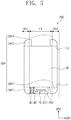
- FIG. 5 is a plan view illustrating the display panel of FIG. 4
- FIG. 6 is a cross-sectional view taken along a line I-I' of FIG. 4 .
- a size of the window member 100 may be greater than that of the display panel 200 when viewed in a plan view.
- a central portion CP, a corner portion CNP and a pad portion PDP may be defined within the display panel 200.
- the central portion CP, the corner portion CNP and the pad portion PDP may be components for describing a shape of the display panel 200.
- the central portion CP, the corner portion CNP and the pad portion PDP may constitute a single unitary body.
- the central portion CP may have a quadrilateral shape (e.g., a rectangular shape).
- the central portion CP which includes short sides extending primarily in the first direction DR1 and long sides extending primarily in the second direction DR2, is illustrated as an example in FIGS. 4 and 5 .
- the corner portion CNP may protrude from the short sides of the central portion CP in the second direction DR2.
- the corner portion CNP may overlap with the bent portion BA1 and BA2 and the flat portion FA.
- the corner portion CNP may include first to fourth corner portions CNP1 to CNP4.
- the first and second corner portions CNP1 and CNP2 may protrude from end portions of a first short side 11 of the central portion CP and may be spaced apart from each other.
- the third and fourth corner portions CNP3 and CNP4 may protrude from end portions of a second short side 12 of the central portion CP and may be spaced apart from each other.
- the first and third corner portions CNP1 and CNP3 may overlap with the first bent portion BA1 and the flat portion FA.
- the second and fourth corner portions CNP2 and CNP4 may overlap with the second bent portion BA2 and the flat portion FA.
- the pad portion PDP may extend from the first short side 11 of the central portion CP in parallel to the second direction DR2.
- the pad portion PDP may overlap with the flat portion FA.
- the pad portion PDP may be disposed between the first and second corner portions CNP1 and CNP2 and may be spaced apart from the first and second corner portions CNP1 and CNP2.
- a driving integrated circuit DIC may be mounted directly on the pad portion PDP.
- the driving integrated circuit DIC may provide signals necessary for driving the display panel 200.
- a plurality of pads PD may be disposed on the pad portion PDP.
- the pad portion PDP may be connected to the flexible printed circuit board or the printed circuit board through the pads PD.
- the pad portion PDP When the display device 1000 is assembled, the pad portion PDP may be bent to be disposed on a rear surface of the central portion CP.
- FIG. 4 illustrates a state in which the pad portion PDP is bent
- FIG. 5 illustrates a state in which the pad portion PDP is stretched out.
- the driving integrated circuit DIC mounted directly on the pad portion PDP is illustrated as an example.
- the driving integrated circuit DIC might not be mounted on the pad portion PDP but may be mounted on a flexible printed circuit board connected to the pad portion PDP.
- a width W1 of each of the first and second corner portions CNP1 and CNP2 in the second direction DR2 may be equal to or less than a width W2 of the pad portion PDP in the second direction DR2.
- the waterproof member 300 may include sealing members SM1 to SM4 and adhesives AD1 to AD4.
- the first to fourth sealing members SM1 to SM4 may be adhesive films.
- the first sealing member SM1 may be disposed on a rear surface of the display panel 200 and may have a shape extending primarily along a long side of the display panel 200 in the second direction DR2.
- the first sealing member SM1 may overlap with the first and third corner portions CNP1 and CNP3 and the central portion CP.
- the first sealing member SM1 may overlap with the first bent portion BA1 and the flat portion FA.
- the second sealing member SM2 may be disposed on a rear surface of the window member 100 and may have a shape which extends primarily in the first direction DR1 outside the first short side 11 of the central portion CP of the display panel 200.
- the second sealing member SM2 may be spaced apart from the display panel 200 and may be disposed between the first and second corner portions CNP1 and CNP2.
- the second sealing member SM2 may overlap with the flat portion FA.
- the third sealing member SM3 may be disposed on the rear surface of the display panel 200 and may have a shape extending primarily along another long side of the display panel 200 in the second direction DR2.
- the third sealing member SM3 may overlap with the second and fourth corner portions CNP2 and CNP4 and the central portion CP.
- the third sealing member SM3 may overlap with the second bent portion BA2 and the flat portion FA.
- the fourth sealing member SM4 may be disposed on the rear surface of the window member 100 and may have a shape which extends primarily in the first direction DR1 outside the second short side 12 of the central portion CP of the display panel 200.
- the fourth sealing member SM4 may be spaced apart from the display panel 200 and may be disposed between the third and fourth corner portions CNP3 and CNP4.
- the fourth sealing member SM4 may overlap with the flat portion FA.
- the adhesive AD1 to AD4 may include first to fourth adhesives AD1 to AD4.
- the first to fourth adhesives AD1 to AD4 may be curable resin.
- the first adhesive AD1 may be adhered to the first sealing member SM1 and the second sealing member SM2 to prevent water from permeating between the first sealing member SM1 and the second sealing member SM2.
- the second adhesive AD2 may be adhered to the second sealing member SM2 and the third sealing member SM3 to prevent water from permeating between the second sealing member SM2 and the third sealing member SM3.
- the third adhesive AD3 may be adhered to the first sealing member SM1 and the fourth sealing member SM4 to prevent water from permeating between the first sealing member SM1 and the fourth sealing member SM4.
- the fourth adhesive AD4 may be adhered to the third sealing member SM3 and the fourth sealing member SM4 to prevent water from permeating between the third sealing member SM3 and the fourth sealing member SM4.
- the first to fourth sealing members SM1 to SM4 and the first to fourth adhesives AD1 to AD4 may prevent water from permeating into a space between the display panel 200 and the bracket 500.
- the first to fourth sealing members SM1 and SM4 and the first to fourth adhesives AD1 to AD4 may be adhered to the bracket 500 described above with reference to FIG. 2 .
- components may be at least similar to corresponding components that have already been described.
- a space between a first sealing member and a second sealing member may be defined within a bent portion, and a first adhesive portion may overlap with the bent portion and may be adhered to the first sealing member and the second sealing member.
- a plurality of layers constituting the display panel may be separated from each other due to differences in restoring force between the plurality of layers.
- water may permeate to a rear surface of the display panel through a space between the plurality of layers.
- the first to fourth adhesives AD1 to AD4 may fill spaces between the first, second, third and fourth sealing members SM1 to SM4, which are defined within the flat portion FA.
- the first to fourth adhesives AD1 to AD4 can prevent water from permeating to the rear surface of the display panel 200.
- FIG. 7 is a plan view illustrating a window member, a display panel and a waterproof member in a display device according to an exemplary embodiment of the present invention.
- a central portion CP1, a corner portion CNPN and a pad portion PDP1 may be defined within a display panel 201.
- the corner portion CNPN may include first and second corner portions CNPN1 and CNPN2.
- the first and second corner portions CNPN1 and CNPN2 may be substantially the same as the first and second corner portions CNP1 and CNP2 described with reference to FIG. 4 .
- a waterproof member 301 may include a sealing member SM11, SM12, SM13 and SM14 and an adhesive AD11 and AD12.
- a first sealing member SM11 may be disposed on a rear surface of the display panel 201 and may have a shape extending primarily along a long side of the display panel 201 in the second direction DR2.
- the first sealing member SM11 may overlap with the first corner portion CNPN1 and the central portion CP1.
- a second sealing member SM12 may be disposed on a rear surface of a window member 100 and may have a shape which extends primarily in the first direction DR1 outside a short side of the display panel 201.
- the second sealing member SM12 may be spaced apart from the display panel 201 and may be disposed between the first and second corner portions CNPN1 and CNPN2.
- the second sealing member SM12 may overlap with the flat portion FA.
- a third sealing member SM13 may be disposed on the rear surface of the display panel 201 and may have a shape extending primarily along another long side of the display panel 201 in the second direction DR2.
- the third sealing member SM13 may be spaced apart from the first sealing member SM11 in the first direction DR1.
- the third sealing member SM13 may overlap with the second corner portion CNPN2 and the central portion CP1.
- a fourth sealing member SM14 may be disposed on the rear surface of the display panel 201 and may have a shape extending primarily along another short side of the display panel 201 in the first direction DR1.
- the fourth sealing member SM14 may be connected to the first and third sealing members SM11 and SM13.
- the first, third and fourth sealing members SM11, SM13 and SM14 may constitute a single unitary body.
- the adhesive AD11 and AD12 may include first and second adhesives AD1 and AD12.
- the first adhesive AD11 may be adhered to the first sealing member SM11 and the second sealing member SM12 to prevent water from permeating between the first sealing member SM11 and the second sealing member SM12.
- the second adhesive AD12 may be adhered to the second sealing member SM12 and the third sealing member SM13 to prevent water from permeating between the second sealing member SM12 and the third sealing member SM13.
- the first, third and fourth sealing members SM11, SM13 and SM14 constituting the single unitary body may be adhered to the rear surface of the display panel 201.
- the first and second adhesives AD11 and AD12 may prevent water from permeating to the rear surface of the display panel 201.
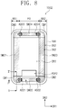
- FIG. 8 is a plan view illustrating a window member, a display panel and a waterproof member in a display device according to an exemplary embodiment of the present invention
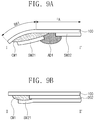
- FIG. 9A is a cross-sectional view taken along a line I-I' of FIG. 8
- FIG. 9B is a cross-sectional view taken along a line II-II' of FIG. 8 .
- a central portion CP2 and a pad portion PDP2 may be defined within a display panel 202 of the display device 1002.
- the first to fourth corner portions CNP1 to CNP4 are not defined within the display panel 202.
- the display device 1002 may further include first to fourth compensation parts CM1 to CM4.
- the first to fourth compensation parts CM1 to CM4 may be disposed at positions at which the first to fourth corner portions CNP1 to CNP4 of the display panel 200 of FIG. 4 are disposed.
- Planar shapes of the first to fourth compensation parts CM1 to CM4 may be substantially the same as those of the first to fourth corner portions CNP1 to CNP4 described with reference to FIG. 4 .
- the first to fourth compensation parts CM1 to CM4 may be in contact with the window member 100 and the display panel 202.
- the first to fourth compensation parts CM1 to CM4 may be curable resin and may partially overlap with the central portion CP2.
- the first to fourth compensation parts CM1 to CM4 may be in contact with a rear surface of the display panel 202.
- the first to fourth compensation parts CM1 to CM4 or one ore some of the first to fourth compensation parts CM1 to CM4 may have a more plate like shape like the first to fourth corner portions CNP1 to CNP4 of the display panel 200.
- the first to fourth compensation parts CM1 to CM4 are made from another material than a curable resin
- the first to fourth compensation parts or at least one or several thereof may have a constant thickness in the cross sections as shown in FIGS. 9A, 9B .
- a waterproof member 302 may include a sealing member SM21 to SM24 and an adhesive AD21 to AD24.
- the first to fourth sealing members SM21 to SM24 may have the same shapes as the first to fourth sealing members SM1 to SM4 described with reference to FIGS. 4 to 6 when viewed in a plan view, and thus to the extent that details are omitted herein with respect to sealing member SM21 to SM24, it may be assumed that the omitted details are at least similar to those described above as the first to fourth sealing members SM1 to SM4 described with reference to FIGS. 4 to 6 .
- the first to fourth adhesives AD21 to AD24 may have the same shapes as the first to fourth adhesives AD1 to AD4 described with reference to FIGS. 4 to 6 when viewed in a plan view, and thus to the extent that details are omitted herein with respect to the first to fourth adhesives AD21 to AD24, it may be assumed that the omitted details are at least similar to those described above as the first to fourth adhesives AD1 to AD4 described with reference to FIGS. 4 to 6 .
- the substantially same effects as the above embodiments in which the shape of the display panel is changed may be obtained by the first to fourth compensation parts CM1 to CM4 without changing the shape of the display panel 202.
- the display device may have the flat portion and the bent portion and may effectively prevent water from permeating to the rear surface of the display panel.
- the layers constituting the display panel are separated from each other in the bent portion of the display panel, the layers of the display panel might not be separated from each other in the flat portion of the display panel and the adhesive may prevent water from permeating to the rear surface of the display panel.
Landscapes
- Engineering & Computer Science (AREA)
- Signal Processing (AREA)
- Microelectronics & Electronic Packaging (AREA)
- Physics & Mathematics (AREA)
- Theoretical Computer Science (AREA)
- General Physics & Mathematics (AREA)
- General Engineering & Computer Science (AREA)
- Optics & Photonics (AREA)
- Human Computer Interaction (AREA)
- Devices For Indicating Variable Information By Combining Individual Elements (AREA)
Claims (15)
- Anzeigevorrichtung oder tragbares Endgerät (1000, 1001), umfassend:ein Fensterelement (100), umfassend einen flachen Abschnitt (FA) und einen gebogenen Abschnitt (BA1, BA2), der mit dem flachen Abschnitt (FA) verbunden ist;ein Anzeigefeld (200, 201), das auf einer Rückseite des Fensterelements (100) angeordnet ist und einen Mittelabschnitt (CP) und einen Eckabschnitt (CNP) umfasst, der über den Mittelabschnitt (CP) herausragt und mit dem flachen Abschnitt (FA) und dem gebogenen Abschnitt (BA1, BA2) überlappt;ein erstes Dichtungselement (SM1, SM11), das auf einer Rückseite des Anzeigefelds (200, 201) angeordnet ist und mit dem Eckabschnitt (CNP) überlappt;ein zweites Dichtungselement (SM2, SM12), das auf der Rückseite des Fensterelements (100) angeordnet ist und von dem Mittelabschnitt (CP) und dem Eckabschnitt (CNP) beabstandet ist;einen ersten Klebstoff (AD1, AD11), der das erste Dichtungselement (SM1, SM11) und das zweite Dichtungselement (SM2, SM12) berührt und einen Raum abdichtet, der zwischen dem ersten Dichtungselement (SM1, SM11) und dem zweiten Dichtungselement (SM2, SM12) in dem flachen Abschnitt (FA) definiert ist.
- Anzeigevorrichtung oder tragbares Endgerät (1000, 1001) nach Anspruch 1, wobei der Eckabschnitt (CNP) einen ersten und zweiten Eckabschnitt (CNP1, CNP2, CNPN1, CNPN2) umfasst, die über eine Seite des Mittelabschnitts (CP) herausragen,
wobei der erste und der zweite Eckabschnitt (CNP1, CNP2, CNPN1, CNPN2) voneinander beabstandet sind, und
wobei das zweite Dichtungselement (SM2, SM12) zwischen dem ersten und dem zweiten Eckabschnitt (CNP1, CNP2, CNPN1, CNPN2) angeordnet ist. - Anzeigevorrichtung oder tragbares Endgerät (1000, 1001) nach Anspruch 2, ferner umfassend:ein drittes Dichtungselement (SM3, SM13), das auf der Rückseite des Anzeigefelds (200, 201) angeordnet ist, mit dem zweiten Eckabschnitt (CNP2, CNPN2) überlappt und von dem ersten Dichtungselement (SM1, SM11) beabstandet ist; undeinen zweiten Klebstoff (AD2, AD12), der das zweite Dichtungselement (SM2, SM12) und das dritte Dichtungselement (SM3, SM13) berührt und einen Raum abdichtet, der zwischen dem zweiten Dichtungselement (SM2, SM12) und dem dritten Dichtungselement (SM3, SM13) in dem flachen Abschnitt (FA) definiert ist, wobei das erste Dichtungselement (SM1, SM11) mit dem ersten Eckabschnitt (CNP1, CNPN1) überlappt.
- Anzeigevorrichtung oder tragbares Endgerät (1000) nach Anspruch 3, ferner umfassend:ein viertes Dichtungselement (SM4), das auf der Rückseite des Fensterelements (100) angeordnet ist,wobei der Eckabschnitt (CNP) ferner einen dritten und vierten Eckabschnitt (CNP3, CNP4) umfasst, die über eine andere Seite des Mittelabschnitts (CP) herausragen und voneinander beabstandet sind,wobei die andere Seite des Mittelabschnitts (CP) der einen Seite des Mittelabschnitts (CP) gegenüberliegt, undwobei das vierte Dichtungselement (SM4) zwischen dem dritten und vierten Eckabschnitt (CNP3, CNP4) angeordnet ist.
- Anzeigevorrichtung oder tragbares Endgerät (1000) nach Anspruch 4, ferner umfassend:einen dritten Klebstoff (AD3), der das erste Dichtungselement (SM1) und das vierte Dichtungselement (SM4) berührt, und einen Raum abdichtet, der zwischen dem ersten Dichtungselement (SM1) und dem vierten Dichtungselement (SM4) in dem flachen Abschnitt (FA) definiert ist; undeinen vierten Klebstoff (AD4), der das dritte Dichtungselement (SM3) und das vierte Dichtungselement (SM4) berührt und einen Raum abdichtet, der zwischen dem dritten Dichtungselement (SM3) und dem vierten Dichtungselement (SM4) in dem flachen Abschnitt (FA) definiert ist,wobei das erste Dichtungselement (SM1) mit dem dritten Eckabschnitt (CNP3) überlappt und das dritte Dichtungselement (SM3) mit dem vierten Eckabschnitt (CNP4) überlappt.
- Anzeigevorrichtung oder tragbares Endgerät (1001) nach Anspruch 3, ferner umfassend:
ein viertes Dichtungselement (SM14), das auf der Rückseite des Anzeigefelds (200, 201) angeordnet ist und mit dem ersten Dichtungselement (SM11) und dem dritten Dichtungselement (SM13) verbunden ist. - Anzeigevorrichtung oder tragbares Endgerät (1000, 1001) nach zumindest einem der Ansprüche 1 bis 6, ferner umfassend:
eine Halterung (500), die dazu ausgelegt ist, das Anzeigefeld (200, 201) zu halten, und an die das erste Dichtungselement (SM1, SM11), das zweite Dichtungselement (SM2, SM12) und der erste Klebstoff (AD1, AD11) geklebt werden. - Anzeigevorrichtung oder tragbares Endgerät (1000, 1001) nach zumindest einem der Ansprüche 1 bis 7, wobei der gebogene Abschnitt (BA1, BA2) Folgendes umfasst: einen ersten gebogenen Abschnitt (BA1) und einen zweiten gebogenen Abschnitt (BA2), die einander gegenüberliegen, wobei der flache Abschnitt (FA) zwischen diesen liegt.
- Anzeigevorrichtung oder tragbares Endgerät (1000, 1001) nach zumindest einem der Ansprüche 1 bis 8, ferner umfassend:eine Ansteuerschaltung, die dazu ausgelegt ist, ein Signal zum Ansteuern des Anzeigefelds (200, 201) bereitzustellen,wobei das Anzeigefeld (200, 201) ferner einen Kontaktabschnitt (PDP, PDP1) umfasst, der über den Mittelabschnitt (CP) herausragt und von dem Eckabschnitt (CNP) beabstandet ist und auf dem die Ansteuerschaltung montiert ist, undwobei der Kontaktabschnitt (PDP, PDP1) gebogen ist, um sich mit dem Mittelteil (CP) zu überlappen.
- Anzeigevorrichtung oder tragbares Endgerät (1000, 1001) nach zumindest einem der Ansprüche 7 bis 9, ferner umfassend:
ein Gehäuseunterteil (600), das dazu ausgelegt ist, das Anzeigefeld (200, 201) und die Halterung (500) aufzunehmen, und das an das Fensterelement (100) gekoppelt ist. - Anzeigevorrichtung oder tragbares Endgerät (1000, 1001) nach zumindest einem der Ansprüche 1 bis 10, wobei der erste Klebstoff (AD1, AD11) ein härtbares Harz beinhaltet.
- Anzeigevorrichtung oder tragbares Endgerät (1000, 1001) nach zumindest einem der Ansprüche 2 bis 11, wobei sich die Seite des Mittelabschnitts (CP), über die der erste und der zweite Eckabschnitt (CNP1, CNP2, CNPN1, CNPN2) herausragen, hauptsächlich in einer ersten Richtung (DR1) erstreckt, und der erste und der zweite Eckabschnitt (CNP1, CNP2, CNPN1, CNPN2) von der Seite in einer zweiten Richtung (DR2) herausragen, die die erste Richtung (DR1) schneidet.
- Anzeigevorrichtung oder tragbares Endgerät (1002), umfassend:ein Fensterelement (100), umfassend einen flachen Abschnitt (FA) und einen gebogenen Abschnitt (BA1, BA2), der mit dem flachen Abschnitt (FA) verbunden ist;ein Anzeigefeld (202), das auf einer Rückseite des Fensterelements (100) angeordnet ist und einen Mittelabschnitt (CP2) umfasst;ein erstes Dichtungselement (SM21), das auf einer Rückseite des Anzeigefelds (202) angeordnet ist und mit dem flachen Abschnitt (FA) und dem gebogenen Abschnitt (BA1, BA2) überlappt;ein zweites Dichtungselement (SM22), das auf der Rückseite des Fensterelements (100) angeordnet ist und von dem Mittelabschnitt (CP2) und/oder dem Anzeigefeld (2) beabstandet ist;dadurch gekennzeichnet, dasszumindest ein erstes Ausgleichsteil (CM1) neben dem Mittelabschnitt (CP2) angeordnet ist oder über den Mittelabschnitt (CP2) herausragt und mit dem flachen Abschnitt (FA) und dem gebogenen Abschnitt (BA1, BA2) überlappt;das erste Dichtungselement (SM21) mit dem ersten Ausgleichsteil (CM1) überlappt;das zweite Dichtungselement (SM22) von dem ersten Ausgleichsteil (CM1) beabstandet ist;ein erster Klebstoff (AD21) das erste Dichtungselement (SM21) und das zweite Dichtungselement (SM22) berührt und einen Raum abdichtet, der zwischen dem ersten Dichtungselement (SM21) und dem zweiten Dichtungselement (SM22) in dem flachen Abschnitt (FA) definiert ist.
- Anzeigevorrichtung oder tragbares Endgerät (1002) nach Anspruch 13, ferner umfassend:ein drittes Dichtungselement (SM23), das auf der Rückseite des Anzeigefelds (202) angeordnet ist und von dem ersten Dichtungselement (SM21) beabstandet ist;ein zweites Ausgleichsteil (CM2), das neben dem Anzeigefeld (202) positioniert ist oder über das Anzeigefeld (202) herausragt und mit dem dritten Dichtungselement (SM23) überlappt; undeinen zweiten Klebstoff (AD22), der das zweite Dichtungselement (SM22) und das dritte Dichtungselement (SM23) berührt und einen Raum abdichtet, der zwischen dem zweiten Dichtungselement (SM22) und dem dritten Dichtungselement (SM23) in dem flachen Abschnitt definiert ist.
- Anzeigevorrichtung oder tragbares Endgerät (1002) nach Anspruch 14, ferner umfassend:ein viertes Dichtungselement (SM24), das auf der Rückseite des Anzeigefelds (202) angeordnet ist und von dem ersten Dichtungselement (SM21) und dem dritten Dichtungselement (SM23) beabstandet ist;ein drittes Ausgleichsteil (CM3), das neben dem Anzeigefeld (202) positioniert ist oder über das Anzeigefeld (202) herausragt und mit dem ersten Dichtungselement (SM21) überlappt;ein viertes Ausgleichsteil (CM4), das neben dem Anzeigefeld (202) positioniert ist oder über das Anzeigefeld (202) herausragt und mit dem dritten Dichtungselement (SM23) überlappt; undeinen dritten Klebstoff (AD23), der das erste Dichtungselement (SM21) und das vierte Dichtungselement (SM24) berührt und einen Raum abdichtet, der zwischen dem ersten Dichtungselement (SM21) und dem vierten Dichtungselement (SM24) in dem flachen Abschnitt definiert ist; undeinen vierten Klebstoff (AD24), der das dritte Dichtungselement (SM23) und das vierte Dichtungselement (SM24) berührt und einen Raum abdichtet, der zwischen dem dritten Dichtungselement (SM23) und dem vierten Dichtungselement (SM24) in dem flachen Abschnitt definiert ist.
Applications Claiming Priority (1)
| Application Number | Priority Date | Filing Date | Title |
|---|---|---|---|
| KR1020180002397A KR102420438B1 (ko) | 2018-01-08 | 2018-01-08 | 표시 장치 및 휴대용 단말기 |
Publications (2)
| Publication Number | Publication Date |
|---|---|
| EP3509280A1 EP3509280A1 (de) | 2019-07-10 |
| EP3509280B1 true EP3509280B1 (de) | 2020-07-08 |
Family
ID=65011858
Family Applications (1)
| Application Number | Title | Priority Date | Filing Date |
|---|---|---|---|
| EP19150505.6A Active EP3509280B1 (de) | 2018-01-08 | 2019-01-07 | Wasserdichte anzeigevorrichtung oder tragbares endgerät |
Country Status (4)
| Country | Link |
|---|---|
| US (1) | US10721830B2 (de) |
| EP (1) | EP3509280B1 (de) |
| KR (1) | KR102420438B1 (de) |
| CN (1) | CN110021231B (de) |
Families Citing this family (17)
| Publication number | Priority date | Publication date | Assignee | Title |
|---|---|---|---|---|
| KR102367881B1 (ko) | 2017-07-03 | 2022-02-25 | 삼성디스플레이 주식회사 | 표시 장치 |
| CN110972418B (zh) * | 2018-09-30 | 2022-01-07 | 比亚迪股份有限公司 | 电子设备壳体、电子设备和复合体 |
| CN109920938B (zh) * | 2019-03-26 | 2021-03-19 | 京东方科技集团股份有限公司 | Oled显示面板及oled显示装置 |
| KR102628165B1 (ko) * | 2019-04-23 | 2024-01-23 | 삼성디스플레이 주식회사 | 표시 장치 |
| KR102805224B1 (ko) | 2019-07-15 | 2025-05-12 | 엘지전자 주식회사 | 냉장고 및 냉장고의 제어방법 |
| USD947805S1 (en) * | 2019-09-24 | 2022-04-05 | Beijing Xiaomi Mobile Software Co., Ltd. | Mobile phone with graphical user interface |
| USD945390S1 (en) * | 2019-09-24 | 2022-03-08 | Beijing Xiaomi Mobile Software Co., Ltd. | Mobile phone with animated graphical user interface |
| USD976225S1 (en) * | 2019-09-24 | 2023-01-24 | Beijing Xiaomi Mobile Software Co., Ltd. | Mobile phone with graphical user interface |
| USD962989S1 (en) * | 2019-10-15 | 2022-09-06 | Beijing Xiaomi Mobile Software Co., Ltd. | Mobile phone with graphical user interface |
| KR102745243B1 (ko) | 2019-12-20 | 2024-12-20 | 삼성전자주식회사 | 접착부를 포함하는 전자 장치 |
| KR102881194B1 (ko) * | 2020-03-18 | 2025-11-05 | 삼성디스플레이 주식회사 | 표시 장치의 제조 장치, 및 이를 이용한 표시 장치의 제조 방법 |
| CN116419958A (zh) | 2020-11-05 | 2023-07-11 | 三星电子株式会社 | 包括防水结构的电子装置 |
| KR102955228B1 (ko) * | 2021-04-29 | 2026-04-22 | 삼성전자주식회사 | 방수 구조를 포함하는 전자 장치 |
| CN113140166B (zh) * | 2021-05-13 | 2022-10-18 | 业成科技(成都)有限公司 | 穿戴式装置 |
| US12532619B2 (en) * | 2021-11-02 | 2026-01-20 | Boe Technology Group Co., Ltd. | Display substrate and display apparatus |
| KR20240147839A (ko) * | 2023-03-30 | 2024-10-10 | 삼성디스플레이 주식회사 | 표시 장치 |
| KR20240174689A (ko) * | 2023-06-09 | 2024-12-17 | 삼성전자주식회사 | 휴대용 전자기기 |
Family Cites Families (18)
| Publication number | Priority date | Publication date | Assignee | Title |
|---|---|---|---|---|
| FR2904508B1 (fr) * | 2006-07-28 | 2014-08-22 | Saint Gobain | Dispositif electroluminescent encapsule |
| KR101389480B1 (ko) | 2007-11-14 | 2014-04-25 | 엘지디스플레이 주식회사 | 광학시트 및 이를 이용한 액정표시장치 |
| JP5457226B2 (ja) * | 2010-02-26 | 2014-04-02 | 富士通株式会社 | シール構造、電子装置、携帯装置及びシール方法 |
| ES2548427T3 (es) * | 2010-07-22 | 2015-10-16 | Ferro Corporation | Dispositivo electrónico sellado herméticamente que usa escamas de vidrio revestido |
| JP5637792B2 (ja) | 2010-09-30 | 2014-12-10 | リンテック株式会社 | 両面粘着テープ及びタッチパネル付き表示装置 |
| KR101212172B1 (ko) * | 2012-07-31 | 2012-12-13 | 한국기계연구원 | 표시 장치 |
| KR102117890B1 (ko) * | 2012-12-28 | 2020-06-02 | 엘지디스플레이 주식회사 | 플렉서블 표시 장치 및 플렉서블 표시 장치 제조 방법 |
| KR102056314B1 (ko) * | 2013-09-27 | 2019-12-17 | 삼성디스플레이 주식회사 | 보호용 윈도우 및 이를 포함하는 가요성 표시 장치 |
| KR102315659B1 (ko) * | 2013-11-27 | 2021-10-20 | 가부시키가이샤 한도오따이 에네루기 켄큐쇼 | 표시 장치 |
| KR102132697B1 (ko) * | 2013-12-05 | 2020-07-10 | 엘지디스플레이 주식회사 | 휘어진 디스플레이 장치 |
| KR102133452B1 (ko) * | 2013-12-11 | 2020-07-14 | 삼성디스플레이 주식회사 | 표시 장치 |
| KR102163406B1 (ko) * | 2014-02-21 | 2020-10-08 | 삼성전자주식회사 | 전자 장치 및 그의 하우징 제작 방법 |
| KR20160058329A (ko) * | 2014-11-14 | 2016-05-25 | 삼성디스플레이 주식회사 | 가요성 표시 장치 |
| KR102514770B1 (ko) * | 2015-10-02 | 2023-03-29 | 삼성전자주식회사 | 방수 구조를 포함하는 전자 장치 |
| US9872408B2 (en) * | 2015-10-02 | 2018-01-16 | Samsung Electronics Co., Ltd. | Electronic device including waterproof structure |
| KR102604087B1 (ko) * | 2016-06-24 | 2023-11-21 | 삼성디스플레이 주식회사 | 윈도우 및 이를 포함하는 표시 장치 |
| KR102556829B1 (ko) * | 2016-06-29 | 2023-07-19 | 삼성디스플레이 주식회사 | 터치 기능을 갖는 표시 패널 및 이를 포함하는 표시 장치 |
| KR102374561B1 (ko) * | 2017-06-19 | 2022-03-15 | 삼성디스플레이 주식회사 | 표시 장치 및 입력감지부재 |
-
2018
- 2018-01-08 KR KR1020180002397A patent/KR102420438B1/ko active Active
-
2019
- 2019-01-07 EP EP19150505.6A patent/EP3509280B1/de active Active
- 2019-01-08 CN CN201910014994.5A patent/CN110021231B/zh active Active
- 2019-01-08 US US16/242,178 patent/US10721830B2/en active Active
Non-Patent Citations (1)
| Title |
|---|
| None * |
Also Published As
| Publication number | Publication date |
|---|---|
| CN110021231B (zh) | 2022-10-04 |
| CN110021231A (zh) | 2019-07-16 |
| KR20190085199A (ko) | 2019-07-18 |
| KR102420438B1 (ko) | 2022-07-14 |
| US10721830B2 (en) | 2020-07-21 |
| EP3509280A1 (de) | 2019-07-10 |
| US20190239374A1 (en) | 2019-08-01 |
Similar Documents
| Publication | Publication Date | Title |
|---|---|---|
| EP3509280A1 (de) | Wasserdichte anzeigevorrichtung und tragbares endgerät | |
| US10349523B2 (en) | Printed circuit board and display device including the same | |
| EP3564779B1 (de) | Anzeigevorrichtung und tragbares endgerät | |
| US10361384B2 (en) | Displays with shared flexible substrates | |
| US10091884B2 (en) | Display device with a reinforcing member for improved durability | |
| US9270267B2 (en) | Touch panel and method of manufacturing the same | |
| EP3987758B1 (de) | Elektronische vorrichtung mit kameramodul | |
| CN110851008B (zh) | 显示装置和制造该显示装置的方法 | |
| CN107545843B (zh) | 包括窗部件的显示装置 | |
| US11735121B2 (en) | Display apparatus | |
| KR20170093832A (ko) | 화상 처리 장치, 표시 시스템, 및 전자 기기 | |
| KR102856743B1 (ko) | 표시 장치 | |
| US11445297B2 (en) | Display device | |
| KR20180049418A (ko) | 표시장치 | |
| US12363844B2 (en) | Display module and display device | |
| TW201530400A (zh) | 觸控裝置 | |
| US11849612B2 (en) | Display panel, display device including same, and method for manufacturing display device | |
| US8878805B2 (en) | Touch panel vibrator with reduced reflectance | |
| KR20200131384A (ko) | 입력 감지 유닛, 그것을 포함하는 표시 장치 및 그것의 제조 방법 | |
| KR102816203B1 (ko) | 음향 발생 장치를 갖는 회로 보드와 그를 포함하는 표시 장치 | |
| US8878804B2 (en) | Touch panel vibrator with reduced visibility | |
| CN112736115B (zh) | 制作电路板的方法和包含电路板的显示装置 | |
| US20260101785A1 (en) | Display device and electronic device including the same | |
| CN121057468A (zh) | 制造显示模块的方法 |
Legal Events
| Date | Code | Title | Description |
|---|---|---|---|
| PUAI | Public reference made under article 153(3) epc to a published international application that has entered the european phase |
Free format text: ORIGINAL CODE: 0009012 |
|
| STAA | Information on the status of an ep patent application or granted ep patent |
Free format text: STATUS: THE APPLICATION HAS BEEN PUBLISHED |
|
| STAA | Information on the status of an ep patent application or granted ep patent |
Free format text: STATUS: REQUEST FOR EXAMINATION WAS MADE |
|
| AK | Designated contracting states |
Kind code of ref document: A1 Designated state(s): AL AT BE BG CH CY CZ DE DK EE ES FI FR GB GR HR HU IE IS IT LI LT LU LV MC MK MT NL NO PL PT RO RS SE SI SK SM TR |
|
| AX | Request for extension of the european patent |
Extension state: BA ME |
|
| 17P | Request for examination filed |
Effective date: 20190613 |
|
| RBV | Designated contracting states (corrected) |
Designated state(s): AL AT BE BG CH CY CZ DE DK EE ES FI FR GB GR HR HU IE IS IT LI LT LU LV MC MK MT NL NO PL PT RO RS SE SI SK SM TR |
|
| GRAP | Despatch of communication of intention to grant a patent |
Free format text: ORIGINAL CODE: EPIDOSNIGR1 |
|
| STAA | Information on the status of an ep patent application or granted ep patent |
Free format text: STATUS: GRANT OF PATENT IS INTENDED |
|
| RIC1 | Information provided on ipc code assigned before grant |
Ipc: H04M 1/18 20060101ALI20191217BHEP Ipc: H04M 1/02 20060101AFI20191217BHEP |
|
| INTG | Intention to grant announced |
Effective date: 20200120 |
|
| RAP1 | Party data changed (applicant data changed or rights of an application transferred) |
Owner name: SAMSUNG DISPLAY CO., LTD. |
|
| GRAS | Grant fee paid |
Free format text: ORIGINAL CODE: EPIDOSNIGR3 |
|
| GRAA | (expected) grant |
Free format text: ORIGINAL CODE: 0009210 |
|
| STAA | Information on the status of an ep patent application or granted ep patent |
Free format text: STATUS: THE PATENT HAS BEEN GRANTED |
|
| AK | Designated contracting states |
Kind code of ref document: B1 Designated state(s): AL AT BE BG CH CY CZ DE DK EE ES FI FR GB GR HR HU IE IS IT LI LT LU LV MC MK MT NL NO PL PT RO RS SE SI SK SM TR |
|
| REG | Reference to a national code |
Ref country code: CH Ref legal event code: EP Ref country code: AT Ref legal event code: REF Ref document number: 1289725 Country of ref document: AT Kind code of ref document: T Effective date: 20200715 |
|
| REG | Reference to a national code |
Ref country code: DE Ref legal event code: R096 Ref document number: 602019000228 Country of ref document: DE |
|
| REG | Reference to a national code |
Ref country code: IE Ref legal event code: FG4D |
|
| REG | Reference to a national code |
Ref country code: LT Ref legal event code: MG4D |
|
| REG | Reference to a national code |
Ref country code: AT Ref legal event code: MK05 Ref document number: 1289725 Country of ref document: AT Kind code of ref document: T Effective date: 20200708 |
|
| REG | Reference to a national code |
Ref country code: NL Ref legal event code: MP Effective date: 20200708 |
|
| PG25 | Lapsed in a contracting state [announced via postgrant information from national office to epo] |
Ref country code: NO Free format text: LAPSE BECAUSE OF FAILURE TO SUBMIT A TRANSLATION OF THE DESCRIPTION OR TO PAY THE FEE WITHIN THE PRESCRIBED TIME-LIMIT Effective date: 20201008 Ref country code: SE Free format text: LAPSE BECAUSE OF FAILURE TO SUBMIT A TRANSLATION OF THE DESCRIPTION OR TO PAY THE FEE WITHIN THE PRESCRIBED TIME-LIMIT Effective date: 20200708 Ref country code: FI Free format text: LAPSE BECAUSE OF FAILURE TO SUBMIT A TRANSLATION OF THE DESCRIPTION OR TO PAY THE FEE WITHIN THE PRESCRIBED TIME-LIMIT Effective date: 20200708 Ref country code: GR Free format text: LAPSE BECAUSE OF FAILURE TO SUBMIT A TRANSLATION OF THE DESCRIPTION OR TO PAY THE FEE WITHIN THE PRESCRIBED TIME-LIMIT Effective date: 20201009 Ref country code: HR Free format text: LAPSE BECAUSE OF FAILURE TO SUBMIT A TRANSLATION OF THE DESCRIPTION OR TO PAY THE FEE WITHIN THE PRESCRIBED TIME-LIMIT Effective date: 20200708 Ref country code: AT Free format text: LAPSE BECAUSE OF FAILURE TO SUBMIT A TRANSLATION OF THE DESCRIPTION OR TO PAY THE FEE WITHIN THE PRESCRIBED TIME-LIMIT Effective date: 20200708 Ref country code: BG Free format text: LAPSE BECAUSE OF FAILURE TO SUBMIT A TRANSLATION OF THE DESCRIPTION OR TO PAY THE FEE WITHIN THE PRESCRIBED TIME-LIMIT Effective date: 20201008 Ref country code: PT Free format text: LAPSE BECAUSE OF FAILURE TO SUBMIT A TRANSLATION OF THE DESCRIPTION OR TO PAY THE FEE WITHIN THE PRESCRIBED TIME-LIMIT Effective date: 20201109 Ref country code: ES Free format text: LAPSE BECAUSE OF FAILURE TO SUBMIT A TRANSLATION OF THE DESCRIPTION OR TO PAY THE FEE WITHIN THE PRESCRIBED TIME-LIMIT Effective date: 20200708 Ref country code: LT Free format text: LAPSE BECAUSE OF FAILURE TO SUBMIT A TRANSLATION OF THE DESCRIPTION OR TO PAY THE FEE WITHIN THE PRESCRIBED TIME-LIMIT Effective date: 20200708 |
|
| PG25 | Lapsed in a contracting state [announced via postgrant information from national office to epo] |
Ref country code: RS Free format text: LAPSE BECAUSE OF FAILURE TO SUBMIT A TRANSLATION OF THE DESCRIPTION OR TO PAY THE FEE WITHIN THE PRESCRIBED TIME-LIMIT Effective date: 20200708 Ref country code: PL Free format text: LAPSE BECAUSE OF FAILURE TO SUBMIT A TRANSLATION OF THE DESCRIPTION OR TO PAY THE FEE WITHIN THE PRESCRIBED TIME-LIMIT Effective date: 20200708 Ref country code: LV Free format text: LAPSE BECAUSE OF FAILURE TO SUBMIT A TRANSLATION OF THE DESCRIPTION OR TO PAY THE FEE WITHIN THE PRESCRIBED TIME-LIMIT Effective date: 20200708 Ref country code: IS Free format text: LAPSE BECAUSE OF FAILURE TO SUBMIT A TRANSLATION OF THE DESCRIPTION OR TO PAY THE FEE WITHIN THE PRESCRIBED TIME-LIMIT Effective date: 20201108 |
|
| PG25 | Lapsed in a contracting state [announced via postgrant information from national office to epo] |
Ref country code: NL Free format text: LAPSE BECAUSE OF FAILURE TO SUBMIT A TRANSLATION OF THE DESCRIPTION OR TO PAY THE FEE WITHIN THE PRESCRIBED TIME-LIMIT Effective date: 20200708 |
|
| REG | Reference to a national code |
Ref country code: DE Ref legal event code: R097 Ref document number: 602019000228 Country of ref document: DE |
|
| PG25 | Lapsed in a contracting state [announced via postgrant information from national office to epo] |
Ref country code: IT Free format text: LAPSE BECAUSE OF FAILURE TO SUBMIT A TRANSLATION OF THE DESCRIPTION OR TO PAY THE FEE WITHIN THE PRESCRIBED TIME-LIMIT Effective date: 20200708 Ref country code: SM Free format text: LAPSE BECAUSE OF FAILURE TO SUBMIT A TRANSLATION OF THE DESCRIPTION OR TO PAY THE FEE WITHIN THE PRESCRIBED TIME-LIMIT Effective date: 20200708 Ref country code: EE Free format text: LAPSE BECAUSE OF FAILURE TO SUBMIT A TRANSLATION OF THE DESCRIPTION OR TO PAY THE FEE WITHIN THE PRESCRIBED TIME-LIMIT Effective date: 20200708 Ref country code: RO Free format text: LAPSE BECAUSE OF FAILURE TO SUBMIT A TRANSLATION OF THE DESCRIPTION OR TO PAY THE FEE WITHIN THE PRESCRIBED TIME-LIMIT Effective date: 20200708 Ref country code: DK Free format text: LAPSE BECAUSE OF FAILURE TO SUBMIT A TRANSLATION OF THE DESCRIPTION OR TO PAY THE FEE WITHIN THE PRESCRIBED TIME-LIMIT Effective date: 20200708 Ref country code: CZ Free format text: LAPSE BECAUSE OF FAILURE TO SUBMIT A TRANSLATION OF THE DESCRIPTION OR TO PAY THE FEE WITHIN THE PRESCRIBED TIME-LIMIT Effective date: 20200708 |
|
| PLBE | No opposition filed within time limit |
Free format text: ORIGINAL CODE: 0009261 |
|
| STAA | Information on the status of an ep patent application or granted ep patent |
Free format text: STATUS: NO OPPOSITION FILED WITHIN TIME LIMIT |
|
| PG25 | Lapsed in a contracting state [announced via postgrant information from national office to epo] |
Ref country code: AL Free format text: LAPSE BECAUSE OF FAILURE TO SUBMIT A TRANSLATION OF THE DESCRIPTION OR TO PAY THE FEE WITHIN THE PRESCRIBED TIME-LIMIT Effective date: 20200708 |
|
| 26N | No opposition filed |
Effective date: 20210409 |
|
| PG25 | Lapsed in a contracting state [announced via postgrant information from national office to epo] |
Ref country code: SK Free format text: LAPSE BECAUSE OF FAILURE TO SUBMIT A TRANSLATION OF THE DESCRIPTION OR TO PAY THE FEE WITHIN THE PRESCRIBED TIME-LIMIT Effective date: 20200708 |
|
| PG25 | Lapsed in a contracting state [announced via postgrant information from national office to epo] |
Ref country code: MC Free format text: LAPSE BECAUSE OF FAILURE TO SUBMIT A TRANSLATION OF THE DESCRIPTION OR TO PAY THE FEE WITHIN THE PRESCRIBED TIME-LIMIT Effective date: 20200708 Ref country code: SI Free format text: LAPSE BECAUSE OF FAILURE TO SUBMIT A TRANSLATION OF THE DESCRIPTION OR TO PAY THE FEE WITHIN THE PRESCRIBED TIME-LIMIT Effective date: 20200708 |
|
| PG25 | Lapsed in a contracting state [announced via postgrant information from national office to epo] |
Ref country code: LU Free format text: LAPSE BECAUSE OF NON-PAYMENT OF DUE FEES Effective date: 20210107 |
|
| REG | Reference to a national code |
Ref country code: BE Ref legal event code: MM Effective date: 20210131 |
|
| PG25 | Lapsed in a contracting state [announced via postgrant information from national office to epo] |
Ref country code: IE Free format text: LAPSE BECAUSE OF NON-PAYMENT OF DUE FEES Effective date: 20210107 |
|
| PG25 | Lapsed in a contracting state [announced via postgrant information from national office to epo] |
Ref country code: BE Free format text: LAPSE BECAUSE OF NON-PAYMENT OF DUE FEES Effective date: 20210131 |
|
| REG | Reference to a national code |
Ref country code: CH Ref legal event code: PL |
|
| PG25 | Lapsed in a contracting state [announced via postgrant information from national office to epo] |
Ref country code: LI Free format text: LAPSE BECAUSE OF NON-PAYMENT OF DUE FEES Effective date: 20220131 Ref country code: CH Free format text: LAPSE BECAUSE OF NON-PAYMENT OF DUE FEES Effective date: 20220131 |
|
| P01 | Opt-out of the competence of the unified patent court (upc) registered |
Effective date: 20230516 |
|
| PG25 | Lapsed in a contracting state [announced via postgrant information from national office to epo] |
Ref country code: CY Free format text: LAPSE BECAUSE OF FAILURE TO SUBMIT A TRANSLATION OF THE DESCRIPTION OR TO PAY THE FEE WITHIN THE PRESCRIBED TIME-LIMIT Effective date: 20200708 |
|
| PG25 | Lapsed in a contracting state [announced via postgrant information from national office to epo] |
Ref country code: HU Free format text: LAPSE BECAUSE OF FAILURE TO SUBMIT A TRANSLATION OF THE DESCRIPTION OR TO PAY THE FEE WITHIN THE PRESCRIBED TIME-LIMIT; INVALID AB INITIO Effective date: 20190107 |
|
| PG25 | Lapsed in a contracting state [announced via postgrant information from national office to epo] |
Ref country code: MK Free format text: LAPSE BECAUSE OF FAILURE TO SUBMIT A TRANSLATION OF THE DESCRIPTION OR TO PAY THE FEE WITHIN THE PRESCRIBED TIME-LIMIT Effective date: 20200708 |
|
| PG25 | Lapsed in a contracting state [announced via postgrant information from national office to epo] |
Ref country code: TR Free format text: LAPSE BECAUSE OF FAILURE TO SUBMIT A TRANSLATION OF THE DESCRIPTION OR TO PAY THE FEE WITHIN THE PRESCRIBED TIME-LIMIT Effective date: 20200708 |
|
| PG25 | Lapsed in a contracting state [announced via postgrant information from national office to epo] |
Ref country code: MT Free format text: LAPSE BECAUSE OF FAILURE TO SUBMIT A TRANSLATION OF THE DESCRIPTION OR TO PAY THE FEE WITHIN THE PRESCRIBED TIME-LIMIT Effective date: 20200708 |
|
| PGFP | Annual fee paid to national office [announced via postgrant information from national office to epo] |
Ref country code: GB Payment date: 20251222 Year of fee payment: 8 |
|
| PGFP | Annual fee paid to national office [announced via postgrant information from national office to epo] |
Ref country code: FR Payment date: 20251223 Year of fee payment: 8 |
|
| PGFP | Annual fee paid to national office [announced via postgrant information from national office to epo] |
Ref country code: DE Payment date: 20251222 Year of fee payment: 8 |