EP3510231B1 - System und verfahren zur plattenausrichtung - Google Patents
System und verfahren zur plattenausrichtung Download PDFInfo
- Publication number
- EP3510231B1 EP3510231B1 EP17848291.5A EP17848291A EP3510231B1 EP 3510231 B1 EP3510231 B1 EP 3510231B1 EP 17848291 A EP17848291 A EP 17848291A EP 3510231 B1 EP3510231 B1 EP 3510231B1
- Authority
- EP
- European Patent Office
- Prior art keywords
- external
- segment
- plate
- alignment tool
- slab
- Prior art date
- Legal status (The legal status is an assumption and is not a legal conclusion. Google has not performed a legal analysis and makes no representation as to the accuracy of the status listed.)
- Active
Links
Images


Classifications
-
- E—FIXED CONSTRUCTIONS
- E06—DOORS, WINDOWS, SHUTTERS, OR ROLLER BLINDS IN GENERAL; LADDERS
- E06B—FIXED OR MOVABLE CLOSURES FOR OPENINGS IN BUILDINGS, VEHICLES, FENCES OR LIKE ENCLOSURES IN GENERAL, e.g. DOORS, WINDOWS, BLINDS, GATES
- E06B3/00—Window sashes, door leaves, or like elements for closing wall or like openings; Layout of fixed or moving closures, e.g. windows in wall or like openings; Features of rigidly-mounted outer frames relating to the mounting of wing frames
- E06B3/54—Fixing of glass panes or like plates
-
- E—FIXED CONSTRUCTIONS
- E04—BUILDING
- E04F—FINISHING WORK ON BUILDINGS, e.g. STAIRS, FLOORS
- E04F11/00—Stairways, ramps, or like structures; Balustrades; Handrails
- E04F11/18—Balustrades; Handrails
- E04F11/181—Balustrades
- E04F11/1812—Details of anchoring to the wall or floor
-
- E—FIXED CONSTRUCTIONS
- E04—BUILDING
- E04F—FINISHING WORK ON BUILDINGS, e.g. STAIRS, FLOORS
- E04F11/00—Stairways, ramps, or like structures; Balustrades; Handrails
- E04F11/18—Balustrades; Handrails
- E04F11/181—Balustrades
- E04F11/1851—Filling panels, e.g. concrete, sheet metal panels
- E04F11/1853—Glass panels
-
- E—FIXED CONSTRUCTIONS
- E04—BUILDING
- E04F—FINISHING WORK ON BUILDINGS, e.g. STAIRS, FLOORS
- E04F11/00—Stairways, ramps, or like structures; Balustrades; Handrails
- E04F11/18—Balustrades; Handrails
- E04F2011/1885—Handrails or balusters characterized by the use of specific materials
- E04F2011/1891—Handrails or balusters characterized by the use of specific materials mainly of stone or stone like materials, e.g. concrete; mainly of glass
- E04F2011/1895—Handrails or balusters characterized by the use of specific materials mainly of stone or stone like materials, e.g. concrete; mainly of glass mainly of glass
Definitions
- the present invention relates to alignment of plates. More particularly, the present invention relates to devices, systems and methods for plate stabilizing and alignment.
- Position adjustments for plates of large scale are usually difficult to perform in order to achieve a desired alignment. This difficulty may occur when alignment is applied at one end of the large plate and where a slight movement or misalignment (e.g., of about 2 millimeters) at the that end, e.g. bottom of the plate, translates into a large movement or misalignment (e.g., of about 20 millimeters) at the top for large scale plates, thereby causing an undesired inclination of the plate.
- a slight movement or misalignment e.g., of about 2 millimeters
- misalignment e.g., of about 20 millimeters
- DE 202013104330 U1 discloses the features of the preamble of claim 1. It describes a holding system for an all-glass railing consisting of a U-shaped floor profile for attachment to the ground, in the guide channel of which glass supports and glass wedges are placed in order to place one in the guide channel between the glass supports and glass wedges to hold and fix the glass pane to be received.
- US 4,920,717 describes an ornamental handrail assembly is disclosed which provides an improved base assembly for mounting the glass panels such that the panels are easily leveled without removing the panels from the base assembly.
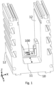
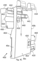
- Fig. 1 illustrates a perspective view of a plate stabilizing device 100 positioned within a portion of an external plate profile 10.
- External U-shaped plate profile 10 includes two walls 12 such that plate stabilizing device 100 may be positioned and/or coupled therebetween, for example engaging base 11 of external plate profile 10. It may be appreciated that only a portion of external U-shaped plate profile 10 is illustrated in Fig. 1 .
- the plate stabilizing device 100 moves along a longitudinal axis 'Y' of external U-shaped plate profile 10, as indicated with a double headed dashed arrow in Fig. 1 , for example for positioning plate stabilizing device 100 in a desired position.
- FIG. 2A illustrates a perspective view of plate stabilizing device 100
- Fig. 2B illustrates a bottom perspective view of the same.
- Plate stabilizing device 100 includes an external segment 110, corresponding in its outer shape to the external U-shaped plate profile 10 and configured to fit therein (e.g., as shown in Fig. 1 ).
- the external segment 110 includes a socket 130 adapted to at least partially accommodate an external alignment tool 170 (e.g., as shown in Fig. 2C ) through a passage serving as a turning point for the external alignment tool 170, as further described hereinafter.
- Plate stabilizing device 100 further includes an internal segment 120, configured to accommodate an end side, such as bottom portion, of the plate and adapted to slide within external segment 110 along a transversal axis 'X' perpendicular to the the longitudinal axis of external segment 110, which coincides with the longitudinal axis 'Y' of the external U-shaped plate profile 10 when installed in it.
- engagement of alignment tool 170 with external segment 110 is configured to indicate an angle of inclination of the plate.
- internal segment 120 includes an alignment tool wedge-like portion 150 capable of accommodating a tip 180 of the alignment tool 170 (e.g., as shown in Fig. 2C ).
- at least one of external segment 110 and internal segment 120 includes an elastic and/or resilient material.
- the internal segment 120 is configured to move transversally to the longitudinal axis 'Y' when external segment 110 slides along the longitudinal axis 'Y', as further described hereinafter.
- the internal segment 120 includes an elastic bottom portion 121 configured to prevent or resist movement of internal segment along the longitudinal axis of base 11 and concurrently allow movement of internal segment 120 transerversal to the longitudiunal axis of base 11 of the external U-shaped plate profile 10 (e.g., as shown in Fig. 1 ). Accordingly, when externlal segment 110 is forced by alignment tool 170 to move along the longitudinal axis, as descrinbed below, internal segment 120 will resist movement with external segment 110 in that direction, but will be forced to move transversally to that direction.
- bottom portion 121 includes an aperture 125.
- the external segment 110 is moved by alignment tool 170 when the alignment tool is inserted through the passage and rests at wedge-like portion 150 such that alignment tool 170 is rotatably turned about the passage thereby sliding external segment 110 along the longitudinal axis 'Y'.
- Fig. 2C illustrates a frontal view of alignment tool 170 engaged with wedge-like portion 150 of internal segment 120, according to some embodiments of the invention.
- the alignment tool 170 is inserted, for instance by a user, into wedge-like portion 150 while internal segment 120 accommodates a bottom portion of the plate, as further describe hereinafter.
- moderate movements by alignment tool 170 may cause external segment 110 to move relatively to internal segment 120 along the longitudinal axis 'Y', and thereby move internal segment 120 along the transversal axis 'X' so as to align the plate accommodated by internal segment 120.
- movement of external segment 110 allows fine-tuning, for instance with long movement of the user causing small movement of the plate stabilizing device.
- Fig. 2E-2F illustrates a frontal partial view of extrnal segment 110 moved to a first end and second end relative to internal segment 120 by alignment tool 170, according to some embodiments of the invention.
- the user moving alignment tool 170 for instance engaged with wedge-like portion 150 of internal segment 120, may move external segment 120 between a first end (as shown in Fig. 2E ) and a second end (as shown in Fig. 2F ).
- alignment tool 170 is reusable and after aligning a first plate, a second plate is aligned in a similar fashion with the same alignment tool 170.
- plate stabilizing device 100 resides just by insertion of alignment tool 170 and realizing its angle of inclination with respect to a predetermined reference angle.
- Fig. 2D illustrates a top view of plate stabilizing device 100, according to some embodiments of the invention. It may be appreciated that external segment 110 is moved, for instance by alignment tool 170, along the longitudinal axis 'Y' of plate stabilizing device 100, thereby moving internal segment 120 along the transverse axis 'X' indicated with a double headed dashed arrow in Fig. 2D .
- external segment 110 includes a first window 210 configured to accommodate a corresponding first projection 220 of internal segment 120, where first projection 220 includes wedge-like portion 150. It may be appreciated that movement of internal segment 120 within external segment 110, for instance external segment 110 moved by alignment tool 170, may cause first projection 220 to move inside first window 210. It should be appreciated that according to some embodiments the range of movement of projection 220 inside window 210 defines the range of tuning.
- the external segment 110 further includes at least one second window 240 configured to accommodate at least one corresponding second projection 260 of internal segment 120.
- internal segment 120 further includes at least one third projection 261, for example shaped as vertical trapezoid. It may be appreciated that second projections 260 is configured to cause the transversal movement when sliding abut inclined surfaces of corresponding second window 240. Similarly to movement within first window 210, movement of internal segment 120 within external segment 110, for instance when external segment 110 moved by alignment tool 170, may cause at least one second projection 260 to move inside at least one second window 240.
- internal segment 120 includes a tilted surface 230 (e.g., tilted in respect to bottom portion 121) corresponding in shape to socket 130 of external segment 110.
- alignment tool 170 moving external segment 110 along the longitudinal axis to a first end may contact socket 130 and tilted surface 230.
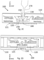
- Figs. 3A-3B illustrate a perspective view and a back perspective view of a plate 300 coupled to plate stabilizing device 100 within external plate profile 10 respectively, according to some embodiments of the invention.
- additional utility elements are coupled and/or attached to external plate profile 10 in order to further stabilize and/or align and/or provide sealing and/or cladding to plate 300.
- Plate 300 may be, for instance, a glass plate of twenty millimeter thickness.
- At least one first hanging profile 301 and/or at least one second hanging profile 303 is attached to a first side 10a of external plate profile 10 in order to attach external plate profile 10 to an existing structure (e.g. attach to a wall).
- at least one first cladding attachment 302 is attached to first side 10a in order to at least partially cover external plate profile 10.
- an elastic barrier 306 is attached to first cladding attachment 302 in order to prevent contact with plate 300.
- a user uses alignment tool 170 (e.g., moving tool 170 along the plane 'YZ') to move external segment 110 located inside plate stabilizing device 100 along the longitudinal axis 'Y', whereby internal segment 120 may not move along the longitudinal axis 'Y' due to coupling with plate 300.
- moving internal segment 120 along the transverse axis 'X' so as to move the bottom end 300a of plate 300 transversally, thereby inclining plate 300 along the plane 'XZ' to a desired inclination angle about inclination fixed point provided by a resilient barrier 30 (e.g. made of glass) thereby enabling alignment of plate 300, prior to attachment of first cladding attachment 302.
- the resilient barrier 30 is attached to external plate profile 10, for instance attached to a top groove 13 in external plate profile 10, in order to provide a longitudinal pivot element and thereby further stabilize plate 300.
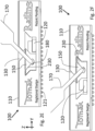
- At least one second cladding attachment 304 is attached to a second side 10b (opposite to first side 10a) of external plate profile 10 in order to at least partially cover external plate profile 10 from the external side.
- an elastic barrier 306 is attached to second cladding attachment 304 in order to prevent contact with plate 300.
- second cladding attachment 304 has a shape and/or size configured to be compatible with an exterior of a wall, for example compatible with a drywall.
- second cladding attachment 304 includes a bottom groove 305 configured to allow engagement with additional external elements.
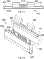
- Figs. 4A-4B illustrate a top view and a perspective view of a plate locking wedge 400 respectively, according to some embodiments of the invention.
- at least one wedge 400 is attached to external plate profile 10 in order to further align plate 300, as further described hereinafter.
- Wedge 400 may include a body 410 configured to attach and/or couple with external plate profile 10.
- Body 410 may include at least one recess configured to allow accommodation of at least one of first slab 420 and second slab 430, wherein the surface of at least one of first slab 420 and second slab 430 may be configured to engage plate 300.
- body 410 is attached to plate 300 while at least one of first slab 420 and second slab 430 is configured to engage with external plate profile 10.
- first slab 420 and second slab 430 is narrower at one end, so as to allow wedge operation including partial movement of the slab along movement line parallel to the longitudinal axis and thereby at least partially engage the plate.
- first slab 420 is narrower at a first end 40a
- second slab 430 is narrower at a second opposite end 430.
- first slab 420 is configured to move within the recess in an opposite direction to the movement of second slab 430. In some embodiments, movement of at least one of first slab 420 and second slab 430 towards the center of wedge 400 may move adjacent plate 300 away from wedge 400. In some embodiments, at least one of first slab 420 and second slab 430 is moved by an external tool, for instance operated by the user.
- Plate locking wedge 400 may further include a tilting lock 440, configured to secure plate locking wedge 400 into it's position within external plate profile 10. It should be appreciated that such securing of the position may allow plate locking wedge 400 to be resilient to force applied by plate 300 upon engagement with plate locking wedge 400, thus maintaining position of plate locking wedge 400.
- tilting lock 440 that swivels about a tilting axis indicated with a dashed arrow marked 'T'.
- Tilting lock 440 may include a first retractable protrusion 441, configured to protrude from back side 40c of wedge 400, and a second retractable protrusion 442, configured to protrude from frontal side 40d of wedge 400, that tilt together with first retractable protrusion 441 about the tilting axis.
- first retractable protrusion 441 protrudes from back side 40c then second retractable protrusion 442 retracts from frontal side 40d, and vice versa when second retractable protrusion 442 protrudes from frontal side 40d then first retractable protrusion 441 retracts from back side 40c and inwards to plate locking wedge 400.
- first retractable protrusion 441 is configured to engage top groove 13 of external plate profile 10 (for instance as shown in Figs. 3A-3B ) in order to abut top groove 13 and thereby secure the position of wedge 400 until first retractable protrusion 441 is retracted and stop abutting top groove 13.
- plate locking wedge 400 further includes at least one stopper 450 configured to resist movement of first slab 420 and/or second slab 430, as further described hereinafter.
- first slab 420 and second slab 430 includes a first channel 460 and a second channel 462.
- First channel 460 may at least partially accommodate stopper 450, so as to limit movement of first slab 420 and/or second slab 430 due to stopper 450 resisting movement thereof.
- any movement of first slab 420 and/or second slab 430 may be refined such that accurate positioning of first slab 420 and/or second slab 430 may be
- the securing of plate locking wedge 400 into it's position within external plate profile 10 is achieved with movement of first slab 420 thereby engaging tilting lock 440 so as to cause first retractable protrusion 441 to abut top groove 13 of external plate profile 10. It should be appreciated that movement of first slab 420 and/or second slab 430, towards the center of plate locking wedge 400, may also tighten the positioning of plate 300 into place, due to the inclined surfaces of first slab 420 and/or second slab 430 that may push plate 300 while moving closer to center of plate locking wedge 400. In some embodiments, movement of first slab 420 and/or second slab 430 is achieved with a dedicated external tool.
- first slab 420 and/or second slab 430 releases the tightening of plate 300.
- first slab 420 and/or second slab 430 is pulled by pulling edges 490 thereof.
- movement of tilting lock 440 e.g., movement of first retractable protrusion 441 to release top groove 13 may be accomplished only when first retractable protrusion 441 is completele moved away from the center of plate locking wedge 400.
- plate locking wedge 400 no longer abuts top groove 13, then it is possible to retrieve plate locking wedge 400 from external plate profile 10, for instance, using a dedicated tool.
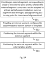
- Figs. 5A-5B shows a flow chart for a method of aligning a plate 300 within an external plate profile 10.
- the method includes providing 501 an external segment 110, corresponding in shape to the external plate profile 10, wherein the external segment 10 includes a socket 130 adapted to at least partially accommodate an external alignment tool 170 through a passage serving as a turning point for the external alignment tool 170, and providing 502 an internal segment 120, configured to accommodate a bottom portion of plate 300 and slide within external segment 110 along the transversal axis of external plate profile 10.
- the method further includes engaging external alignment tool 170 with socket 130, wherein engagement of external segment 110 with external alignment tool 170 is configured to indicate an angle of inclination of the plate 300. In some embodiments, the method further includes providing at least one additional external segment 110 and/or providing at least one additional internal segment 120.
- the internal segment 120 includes an alignment tool wedge-like portion 150 capable of accommodating a tip 180 of the alignment tool 170, and wherein the method further includes engaging tip 180 of external alignment tool 170 with the wedge-like portion 150.
- the method further includes moving internal segment 120 transversally to the longitudinal axis when sliding along the longitudinal axis of external segment 110.
- the method further includes rotatably turning alignment tool 170 about the passage, thereby sliding the external segment along the longitudinal axis.
- the method further includes providing a resilient barrier 30, configured to allow an inclination fixed point for the plate 300.
Landscapes
- Engineering & Computer Science (AREA)
- Architecture (AREA)
- Civil Engineering (AREA)
- Structural Engineering (AREA)
- Connection Of Plates (AREA)
Claims (8)
- System zur Ausrichtung einer Platte umfassend ein externes U-förmiges Plattenprofil (10):eine Vorrichtung zum Stabilisieren der Platte (100) und ein Ausrichtungswerkzeug (170), wobei die Vorrichtung zum Stabilisieren der Platte (100) dazu konfiguriert ist, um mit dem exteren U-förmigen Plattenprofil (10) gekoppelt zu werden, wobei die Vorrichtung wie folgt umfasst:ein externes Segment (110), das dem externen U-förmigen Plattenprofil (10) hinsichtlich der Form entspricht und dazu konfiguriert ist, um dort hinein zu passen; undein internes Segment (120), das dazu konfiguriert ist, um einen unteren Anteil der Platte unterzubringen,dadurch gekennzeichnet, dassdas externe Segment (110) eine Steckaufnahme umfasst, die dazu adaptiert ist, um das externe Ausrichtungswerkzeug mindestens teilweise durch eine Passage hindurch, die als ein Umkehrpunkt für das externe Ausrichtungswerkzeug (170) dient, unterzubringen,wobei das interne Segment (120) einen keilartigen Anteil an einem Ausrichtungswerkzeug (150) umfasst, der fähig ist, eine Spitze (180) des Ausrichtungswerkzeugs (170) unterzubringen, wobei das interne Segment (120) einen elastischen unteren Teil (121) umfasst, der dazu konfiguriert ist, um einer Bewegung des internen Segments (120) entlang einer Längsachse des externen U-förmigen Plattenprofils (10) zu widerstehen,wobei das interne Segment (120) dazu konfiguriert ist, um sich innerhalb des externen Segments (110) quer zu der Längsachse des externen U-förmigen Plattenprofils (10) zu bewegen, wenn das externe Segment (110) durch das Ausrichtungswerkzeug (170) dazu gezwungen wird, sich entlang der Längsachse zu bewegen; undwobei das externe Segment (110) dazu konfiguriert ist, um von dem Ausrichtungswerkzeug (170) bewegt zu werden, wenn das Ausrichtungswerkzeug (170) an dem keilartigen Anteil (150) durch die Passage eingeführt wird, derart, dass das Ausrichtungswerkzeug (170) rotationsfähig umn die Passage gedreht wird, wodurch das externe Segment (110) entlang der Längachse verschoben wird,wobei das externe Segment (110) ferner mindestens ein zweites Fenster (240) aufweist, das dazu konfiguriert ist, um mindestens einen entsprechenden zweiten Vorsprung (260) des internen Segments (120) unterzubringen und wobei der mindestens eine zweite Vorsprung (260) dazu konfiguriert ist, um die Querbewegung zu verursachen, wenn er angrenzend an schiefe Oberflächen des entsprechenden zweiten Fensters (240) verschoben wird.
- System nach Anspruch 1, wobei das externe Segment (110) ein elastisches Material umfasst.
- System nach Anspruch 1 oder 2 ferner umfassend eine robuste Barriere (30), die dazu konfiguriert ist, um einen Neigungs-Fixpunkt für die Platte zuzulassen.
- System nach Anspruch 3 ferner umfassend einen Platten-Verriegelungskeil (400), der dazu konfiguriert ist, um innerhalb des externen U-förmigen Plattenprofils (10) untergebracht zu werden und um in die Platte einzugreifen, wobei der Platten-Verriegelungskeil (400) wie folgt umfasst:ein erstes Stück (420), das eine schiefe Oberfläche hat;ein zweites Stück (430), das eine schiefe Oberfläche hat und dazu konfiguriert ist, um in eine Richtung, die entgegengesetzt zu dem ersten Stück (420) ist, bewegt zu werden; undein Kippschloss (440), das mindestens eine einfahrbare Protrusion (442) hat, das dazu konfiguriert ist, um das erste Stück (420) in dem externen U-förmigen Plattenprofil (10) zum Eingreifen zu bringen, sobald sich das erste Stück (420) bewegt,wobei Bewegung des ersten Stücks (420) und des zweiten Stücks (430) dazu konfiguriert ist, um die schiefen Oberflächen mit der Platte zum Eingreifen zu bringen, sodass die Positionierung der Platte gesichert ist.
- Verfahren zum Ausrichten einer Platte innerhalb eines externen Plattenprofils (10), wobei das Verfahren wie folgt umfasst:Bereitstellen eines externen Segments (110), das dem externen Plattenprofil (10) hinsichtlich der Form entspricht, wobei das externe Segment (110) eine Steckaufnahme (130) umfasst, die dazu adaptiert ist, um ein externes Ausrichtungswerkzeug (170) mindestens teilweise durch eine Passage hindurch, die als ein Umkehrpunkt für das externe Ausrichtungswerkzeug (170) dient, unterzubringen;Bereitstellen eines internen Segments (120), das dazu konfiguriert ist, um einen unteren Anteil der Platte unterzubringen, wobei das intene Segment (120) einen keilartigen Anteil eines Ausrichtungswerkzeugs (150) und einen elastischen unteren Anteil (121) umfasst, entsprechend dazu konfiguriert, um Bewegung des internen Segments (120) entlang einer Längsachse des externen U-förmigen Plattenprofils (10) zu widerstehen;Positionieren des intenen Segments (120) innterhalb des externen Segments (110);Positionieren des externen Segments (110) innerhalb des externen Plattenprofils (10);Unterbringen eines Anteils der Platte in dem internen Segment (120);Unterbringen einer Spitze (180) des Ausrichtungswerkzeugs (170) in dem keilartigen Anteil des Ausrichtungswerkzeugs (150) des internen Segments;Einführen des Ausrichtungswerkzeugs durch die Passage des externen Segments und Ruhen desselben auf dem keilartigen Anteil des internen Segments,wodurch die Spitze (180) des Ausrichtungswerkzeugs (170) in dem keilartigen Anteil (150) zum Eingreifen gebracht wird;Bewegen des externen Segments (110) mit dem externen Ausrichtungswerkzeug (170) durch rotationsartiges Drehen des Ausrichtungswerkzeugs (170) um die Passage, wodurch das externe Segment (110) entlang der Längsachse verschoben wird;Bewegen des internen Segments (120) quer zu der Längsachse, wenn es entlang der Längsachse des externen Segments (110) verschoben wird, mittels mindestens eines zweiten Vorsprungs (260) des internen Segments (120), und es gleitet angrenzend zur schiefen Oberfläche eines entsprechenden zweiten Fensters (240) des externen Segments (110); undAusrichten der Platte in die gewünschte Position.
- Verfahren nach Anspruch 5 ferner umfassend Bereitstellen mindestens eines zusätzlichen externen Segments (110).
- Verfahren nach Anspruch 5 ferner umfassend Bereitstellen mindestens eines zusätzlichen internen Segments (120).
- Verfahren nach Anspruch 5 ferner umfassend Bereitstellen einer robusten Barriere (30), die dazu konfiguriert ist, um einen Neigungs-Fixpunkt für die Platte zuzulassen und Neigen der Platte in einen gewünschten Neigungswinkel, dadurch dass die Platte an dem Neigungs-Fixpunkt mit der robusten Barriere (30) zum Eingreifen gebracht wird.
Applications Claiming Priority (2)
| Application Number | Priority Date | Filing Date | Title |
|---|---|---|---|
| IL247757A IL247757B (en) | 2016-09-11 | 2016-09-11 | System and method for aligning a panel |
| PCT/IL2017/051014 WO2018047179A1 (en) | 2016-09-11 | 2017-09-10 | System and method for plate alignment |
Publications (4)
| Publication Number | Publication Date |
|---|---|
| EP3510231A1 EP3510231A1 (de) | 2019-07-17 |
| EP3510231A4 EP3510231A4 (de) | 2020-05-27 |
| EP3510231B1 true EP3510231B1 (de) | 2025-04-23 |
| EP3510231C0 EP3510231C0 (de) | 2025-04-23 |
Family
ID=57907590
Family Applications (1)
| Application Number | Title | Priority Date | Filing Date |
|---|---|---|---|
| EP17848291.5A Active EP3510231B1 (de) | 2016-09-11 | 2017-09-10 | System und verfahren zur plattenausrichtung |
Country Status (5)
| Country | Link |
|---|---|
| US (1) | US11220823B2 (de) |
| EP (1) | EP3510231B1 (de) |
| IL (1) | IL247757B (de) |
| PL (1) | PL3510231T3 (de) |
| WO (1) | WO2018047179A1 (de) |
Families Citing this family (9)
| Publication number | Priority date | Publication date | Assignee | Title |
|---|---|---|---|---|
| US10934743B2 (en) * | 2016-10-21 | 2021-03-02 | C.R. Laurence Co., Inc. | Taper-loc system improvements |
| GB2555169B (en) * | 2017-07-21 | 2019-10-23 | Pure Vista Ltd | Panel support system and method |
| DE202017105703U1 (de) * | 2017-09-20 | 2018-01-24 | Q-Railing Europe Gmbh & Co. Kg | System zur Ausrichtung von Geländerplatten |
| GB2571143B (en) * | 2018-03-29 | 2020-03-25 | Pure Vista Ltd | Panel support system and method |
| AR114742A1 (es) * | 2018-11-05 | 2020-10-14 | Vernengo Pablo Remo Mazzola | Perfil embutido en una masa de hormigón, para erigir barandas y paneles divisorios |
| US10697170B1 (en) * | 2019-07-29 | 2020-06-30 | Pablo Remo Mazzola Vernengo | Set of extruded shapes for glass balcony railings and enclosures |
| IT201900019988A1 (it) * | 2019-10-29 | 2021-04-29 | Logli Massimo S P A | Supporto per pannello con bloccaggio laterale |
| GB2586681B (en) * | 2020-03-30 | 2021-08-25 | Pure Vista Ltd | System and method of releasably securing a wedge in a gap |
| SK442022A3 (sk) * | 2022-05-02 | 2024-05-22 | Ing. Lacko Vladimír | Naklápací posuvný systém |
Family Cites Families (14)
| Publication number | Priority date | Publication date | Assignee | Title |
|---|---|---|---|---|
| US4763453A (en) | 1986-05-14 | 1988-08-16 | Blumcraft Of Pittsburgh | Door shoe assembly |
| US4920717A (en) | 1989-05-11 | 1990-05-01 | Kawneer Company, Inc. | Ornamental handrail system |
| US6658778B2 (en) * | 2001-09-11 | 2003-12-09 | Craft, Inc. | Picture frame joint and method of assembling same |
| CA2749550C (en) | 2009-01-22 | 2014-09-30 | Austin R. Baer | Adjustable door mounting system |
| IT1403505B1 (it) | 2011-01-24 | 2013-10-31 | L M Dei F Lli Monticelli S R L | Dispositivo di serraggio ed allineamento per profilati ad angolo in condizione di complanarita'. |
| ITBS20120020A1 (it) * | 2012-02-14 | 2013-08-15 | Metalglas Bonomi S R L | Dispositivo di regolazione e/o bloccaggio di una lastra |
| US9777484B2 (en) * | 2013-03-19 | 2017-10-03 | Gregory A. Header | Hinged glass handrail sill |
| DE202013104330U1 (de) | 2013-09-22 | 2013-10-21 | Onlevel B.V. | Fixiersystem für Glasgeländer |
| FR3017909B1 (fr) * | 2014-02-26 | 2016-10-21 | Sb Ingenierie | Dispositif de fixation d'un panneau dans un rail support |
| EP3247843A1 (de) * | 2014-03-25 | 2017-11-29 | IND.I.A. S.p.A. | Verriegelungs- und regulierungsvorrichtung für platten und tafeln |
| FR3055138B1 (fr) * | 2016-08-16 | 2018-08-10 | Sb Ingenierie | Dispositif de fixation d'un panneau de garde corps dans un rail par injection de pate de fixation |
| FR3058743B1 (fr) * | 2016-11-17 | 2019-01-25 | Sb Ingenierie | Agencement pour la fixation d'un panneau dans une rainure au moyen de deux coins opposes |
| GB2566303A (en) * | 2017-09-08 | 2019-03-13 | Fastec Handrail Systems Ltd | Panel support |
| GB2571143B (en) * | 2018-03-29 | 2020-03-25 | Pure Vista Ltd | Panel support system and method |
-
2016
- 2016-09-11 IL IL247757A patent/IL247757B/en active IP Right Grant
-
2017
- 2017-09-10 WO PCT/IL2017/051014 patent/WO2018047179A1/en not_active Ceased
- 2017-09-10 US US16/331,194 patent/US11220823B2/en active Active
- 2017-09-10 EP EP17848291.5A patent/EP3510231B1/de active Active
- 2017-09-10 PL PL17848291.5T patent/PL3510231T3/pl unknown
Also Published As
| Publication number | Publication date |
|---|---|
| EP3510231A1 (de) | 2019-07-17 |
| IL247757B (en) | 2020-11-30 |
| IL247757A0 (en) | 2017-01-31 |
| WO2018047179A1 (en) | 2018-03-15 |
| EP3510231A4 (de) | 2020-05-27 |
| EP3510231C0 (de) | 2025-04-23 |
| US11220823B2 (en) | 2022-01-11 |
| PL3510231T3 (pl) | 2025-11-12 |
| US20190218786A1 (en) | 2019-07-18 |
Similar Documents
| Publication | Publication Date | Title |
|---|---|---|
| EP3510231B1 (de) | System und verfahren zur plattenausrichtung | |
| EP1942227B1 (de) | System und Verfahren zum Halten eines Gehäuses auf einer Schiene | |
| CA2697162C (en) | Partition mounting system and clamp assembly for mounting partition | |
| EP2772171A1 (de) | Duschtüranordnung | |
| US9451133B2 (en) | Spring-loaded mounting housing for a camera | |
| JP2008514882A (ja) | レールへの物体固定装置 | |
| CN103291150B (zh) | 锁扣机构及通过锁扣机构将盖子固定在装置的方法 | |
| US12460444B2 (en) | Alignment guide for a door handle assembly | |
| US10316583B2 (en) | Screening arrangement | |
| US12017318B1 (en) | Accessory mounting system for connection to a work component having an elongated T-shaped slot | |
| CN107559273B (zh) | 连接装置及具有其的显示屏 | |
| JP2016510370A5 (de) | ||
| JP4570426B2 (ja) | 戸板取付具 | |
| JP2009228364A (ja) | 建具 | |
| US9522447B2 (en) | Automotive glass removal tool | |
| JPH09256717A (ja) | 扉取付装置 | |
| JP2003003725A (ja) | 開閉体取付装置 | |
| US10145504B2 (en) | Bracket mounting tool for window covers | |
| JPH0642851B2 (ja) | 引出しの鏡板調整機構 | |
| SE543349C2 (en) | Lamp mount assembly, and lamp assembly comprising lamp mount assembly | |
| JP7270470B2 (ja) | 建具 | |
| CN213359167U (zh) | 一种调节组件及玻璃夹具 | |
| JP2011220038A (ja) | 嵌合部材及び建具 | |
| JP4646817B2 (ja) | カーテンレール用ブラケット | |
| JP2516140Y2 (ja) | 天板と脚部との連結装置 |
Legal Events
| Date | Code | Title | Description |
|---|---|---|---|
| STAA | Information on the status of an ep patent application or granted ep patent |
Free format text: STATUS: THE INTERNATIONAL PUBLICATION HAS BEEN MADE |
|
| PUAI | Public reference made under article 153(3) epc to a published international application that has entered the european phase |
Free format text: ORIGINAL CODE: 0009012 |
|
| STAA | Information on the status of an ep patent application or granted ep patent |
Free format text: STATUS: REQUEST FOR EXAMINATION WAS MADE |
|
| 17P | Request for examination filed |
Effective date: 20190401 |
|
| AK | Designated contracting states |
Kind code of ref document: A1 Designated state(s): AL AT BE BG CH CY CZ DE DK EE ES FI FR GB GR HR HU IE IS IT LI LT LU LV MC MK MT NL NO PL PT RO RS SE SI SK SM TR |
|
| REG | Reference to a national code |
Ref country code: DE Ref legal event code: R079 Free format text: PREVIOUS MAIN CLASS: E06B0003540000 Ipc: E04F0011180000 |
|
| A4 | Supplementary search report drawn up and despatched |
Effective date: 20200423 |
|
| RIC1 | Information provided on ipc code assigned before grant |
Ipc: E04F 11/18 20060101AFI20200417BHEP |
|
| STAA | Information on the status of an ep patent application or granted ep patent |
Free format text: STATUS: EXAMINATION IS IN PROGRESS |
|
| 17Q | First examination report despatched |
Effective date: 20220113 |
|
| GRAP | Despatch of communication of intention to grant a patent |
Free format text: ORIGINAL CODE: EPIDOSNIGR1 |
|
| STAA | Information on the status of an ep patent application or granted ep patent |
Free format text: STATUS: GRANT OF PATENT IS INTENDED |
|
| INTG | Intention to grant announced |
Effective date: 20241118 |
|
| GRAS | Grant fee paid |
Free format text: ORIGINAL CODE: EPIDOSNIGR3 |
|
| GRAA | (expected) grant |
Free format text: ORIGINAL CODE: 0009210 |
|
| STAA | Information on the status of an ep patent application or granted ep patent |
Free format text: STATUS: THE PATENT HAS BEEN GRANTED |
|
| AK | Designated contracting states |
Kind code of ref document: B1 Designated state(s): AL AT BE BG CH CY CZ DE DK EE ES FI FR GB GR HR HU IE IS IT LI LT LU LV MC MK MT NL NO PL PT RO RS SE SI SK SM TR |
|
| REG | Reference to a national code |
Ref country code: GB Ref legal event code: FG4D |
|
| REG | Reference to a national code |
Ref country code: CH Ref legal event code: EP |
|
| REG | Reference to a national code |
Ref country code: DE Ref legal event code: R096 Ref document number: 602017089085 Country of ref document: DE |
|
| REG | Reference to a national code |
Ref country code: IE Ref legal event code: FG4D |
|
| U01 | Request for unitary effect filed |
Effective date: 20250522 |
|
| U07 | Unitary effect registered |
Designated state(s): AT BE BG DE DK EE FI FR IT LT LU LV MT NL PT RO SE SI Effective date: 20250602 |
|
| U20 | Renewal fee for the european patent with unitary effect paid |
Year of fee payment: 9 Effective date: 20250807 |
|
| REG | Reference to a national code |
Ref country code: CH Ref legal event code: U11 Free format text: ST27 STATUS EVENT CODE: U-0-0-U10-U11 (AS PROVIDED BY THE NATIONAL OFFICE) Effective date: 20251001 |
|
| PG25 | Lapsed in a contracting state [announced via postgrant information from national office to epo] |
Ref country code: ES Free format text: LAPSE BECAUSE OF FAILURE TO SUBMIT A TRANSLATION OF THE DESCRIPTION OR TO PAY THE FEE WITHIN THE PRESCRIBED TIME-LIMIT Effective date: 20250423 |
|
| PG25 | Lapsed in a contracting state [announced via postgrant information from national office to epo] |
Ref country code: GR Free format text: LAPSE BECAUSE OF FAILURE TO SUBMIT A TRANSLATION OF THE DESCRIPTION OR TO PAY THE FEE WITHIN THE PRESCRIBED TIME-LIMIT Effective date: 20250724 Ref country code: NO Free format text: LAPSE BECAUSE OF FAILURE TO SUBMIT A TRANSLATION OF THE DESCRIPTION OR TO PAY THE FEE WITHIN THE PRESCRIBED TIME-LIMIT Effective date: 20250723 |
|
| PG25 | Lapsed in a contracting state [announced via postgrant information from national office to epo] |
Ref country code: HR Free format text: LAPSE BECAUSE OF FAILURE TO SUBMIT A TRANSLATION OF THE DESCRIPTION OR TO PAY THE FEE WITHIN THE PRESCRIBED TIME-LIMIT Effective date: 20250423 |
|
| PG25 | Lapsed in a contracting state [announced via postgrant information from national office to epo] |
Ref country code: RS Free format text: LAPSE BECAUSE OF FAILURE TO SUBMIT A TRANSLATION OF THE DESCRIPTION OR TO PAY THE FEE WITHIN THE PRESCRIBED TIME-LIMIT Effective date: 20250723 |
|
| PGFP | Annual fee paid to national office [announced via postgrant information from national office to epo] |
Ref country code: CZ Payment date: 20250821 Year of fee payment: 9 |
|
| PG25 | Lapsed in a contracting state [announced via postgrant information from national office to epo] |
Ref country code: IS Free format text: LAPSE BECAUSE OF FAILURE TO SUBMIT A TRANSLATION OF THE DESCRIPTION OR TO PAY THE FEE WITHIN THE PRESCRIBED TIME-LIMIT Effective date: 20250823 |
|
| PG25 | Lapsed in a contracting state [announced via postgrant information from national office to epo] |
Ref country code: SM Free format text: LAPSE BECAUSE OF FAILURE TO SUBMIT A TRANSLATION OF THE DESCRIPTION OR TO PAY THE FEE WITHIN THE PRESCRIBED TIME-LIMIT Effective date: 20250423 |
|
| PGFP | Annual fee paid to national office [announced via postgrant information from national office to epo] |
Ref country code: CH Payment date: 20251001 Year of fee payment: 9 |
|
| PGFP | Annual fee paid to national office [announced via postgrant information from national office to epo] |
Ref country code: PL Payment date: 20250630 Year of fee payment: 9 |
|
| PG25 | Lapsed in a contracting state [announced via postgrant information from national office to epo] |
Ref country code: SK Free format text: LAPSE BECAUSE OF FAILURE TO SUBMIT A TRANSLATION OF THE DESCRIPTION OR TO PAY THE FEE WITHIN THE PRESCRIBED TIME-LIMIT Effective date: 20250423 |
|
| PLBE | No opposition filed within time limit |
Free format text: ORIGINAL CODE: 0009261 |
|
| STAA | Information on the status of an ep patent application or granted ep patent |
Free format text: STATUS: NO OPPOSITION FILED WITHIN TIME LIMIT |
|
| REG | Reference to a national code |
Ref country code: CH Ref legal event code: L10 Free format text: ST27 STATUS EVENT CODE: U-0-0-L10-L00 (AS PROVIDED BY THE NATIONAL OFFICE) Effective date: 20260304 |
|
| 26N | No opposition filed |
Effective date: 20260126 |