EP3510239B1 - Outil de coupe de fond de trou et procédé d'utilisation - Google Patents
Outil de coupe de fond de trou et procédé d'utilisation Download PDFInfo
- Publication number
- EP3510239B1 EP3510239B1 EP17767878.6A EP17767878A EP3510239B1 EP 3510239 B1 EP3510239 B1 EP 3510239B1 EP 17767878 A EP17767878 A EP 17767878A EP 3510239 B1 EP3510239 B1 EP 3510239B1
- Authority
- EP
- European Patent Office
- Prior art keywords
- tool
- downhole
- cutting tool
- mandrel
- downhole cutting
- Prior art date
- Legal status (The legal status is an assumption and is not a legal conclusion. Google has not performed a legal analysis and makes no representation as to the accuracy of the status listed.)
- Active
Links
Images



Classifications
-
- E—FIXED CONSTRUCTIONS
- E21—EARTH OR ROCK DRILLING; MINING
- E21B—EARTH OR ROCK DRILLING; OBTAINING OIL, GAS, WATER, SOLUBLE OR MELTABLE MATERIALS OR A SLURRY OF MINERALS FROM WELLS
- E21B10/00—Drill bits
- E21B10/26—Drill bits with leading portion, i.e. drill bits with a pilot cutter; Drill bits for enlarging the borehole, e.g. reamers
- E21B10/32—Drill bits with leading portion, i.e. drill bits with a pilot cutter; Drill bits for enlarging the borehole, e.g. reamers with expansible cutting tools
- E21B10/322—Drill bits with leading portion, i.e. drill bits with a pilot cutter; Drill bits for enlarging the borehole, e.g. reamers with expansible cutting tools cutter shifted by fluid pressure
-
- E—FIXED CONSTRUCTIONS
- E21—EARTH OR ROCK DRILLING; MINING
- E21B—EARTH OR ROCK DRILLING; OBTAINING OIL, GAS, WATER, SOLUBLE OR MELTABLE MATERIALS OR A SLURRY OF MINERALS FROM WELLS
- E21B23/00—Apparatus for displacing, setting, locking, releasing or removing tools, packers or the like in boreholes or wells
- E21B23/04—Apparatus for displacing, setting, locking, releasing or removing tools, packers or the like in boreholes or wells operated by fluid means, e.g. actuated by explosion
- E21B23/042—Apparatus for displacing, setting, locking, releasing or removing tools, packers or the like in boreholes or wells operated by fluid means, e.g. actuated by explosion using a single piston or multiple mechanically interconnected pistons
-
- E—FIXED CONSTRUCTIONS
- E21—EARTH OR ROCK DRILLING; MINING
- E21B—EARTH OR ROCK DRILLING; OBTAINING OIL, GAS, WATER, SOLUBLE OR MELTABLE MATERIALS OR A SLURRY OF MINERALS FROM WELLS
- E21B29/00—Cutting or destroying pipes, packers, plugs or wire lines, located in boreholes or wells, e.g. cutting of damaged pipes, of windows; Deforming of pipes in boreholes or wells; Reconditioning of well casings while in the ground
- E21B29/002—Cutting, e.g. milling, a pipe with a cutter rotating along the circumference of the pipe
-
- E—FIXED CONSTRUCTIONS
- E21—EARTH OR ROCK DRILLING; MINING
- E21B—EARTH OR ROCK DRILLING; OBTAINING OIL, GAS, WATER, SOLUBLE OR MELTABLE MATERIALS OR A SLURRY OF MINERALS FROM WELLS
- E21B29/00—Cutting or destroying pipes, packers, plugs or wire lines, located in boreholes or wells, e.g. cutting of damaged pipes, of windows; Deforming of pipes in boreholes or wells; Reconditioning of well casings while in the ground
- E21B29/002—Cutting, e.g. milling, a pipe with a cutter rotating along the circumference of the pipe
- E21B29/005—Cutting, e.g. milling, a pipe with a cutter rotating along the circumference of the pipe with a radially-expansible cutter rotating inside the pipe, e.g. for cutting an annular window
-
- E—FIXED CONSTRUCTIONS
- E21—EARTH OR ROCK DRILLING; MINING
- E21B—EARTH OR ROCK DRILLING; OBTAINING OIL, GAS, WATER, SOLUBLE OR MELTABLE MATERIALS OR A SLURRY OF MINERALS FROM WELLS
- E21B34/00—Valve arrangements for boreholes or wells
- E21B34/06—Valve arrangements for boreholes or wells in wells
- E21B34/14—Valve arrangements for boreholes or wells in wells operated by movement of tools, e.g. sleeve valves operated by pistons or wire line tools
- E21B34/142—Valve arrangements for boreholes or wells in wells operated by movement of tools, e.g. sleeve valves operated by pistons or wire line tools unsupported or free-falling elements, e.g. balls, plugs, darts or pistons
Definitions
- the present invention relates to a downhole tool and method of use, and in particular to downhole tubular cutting tool.
- a particular aspect of the invention relates to a tool string comprising a cutting tool and at least one other downhole tool.
- cement is pumped down the casing and is displaced up the annulus between the casing and the original wellbore.
- the purpose of the cement is to secure the casing in position and ensure that the annulus is sealed.
- a cement plug is placed in the wellbore casing to seal the wellbore casing annulus. It is known to use downhole casing cutters lowered into the casing to cut the casing above the cement plug and to remove the severed casing section from the wellbore. This task involves multiple trips downhole.
- a downhole cutting tool according to claim 1.
- a tool capable of controlling the opening of the fluid flow paths in the downhole cutting tool it may allow the controlled actuation of the cutting tool and at least one other tool on the same tool string. This may facilitate multiple downhole operations to be performed on a single trip.
- Axial force may be applied by a set down weight and/or a ball drop. This may allow the tool to perform a number of downhole tasks in a single trip without having to return to surface or perform multiple trips.
- Drill tools and milling tools that require a high flow rate may be located beneath the cutter tool on the tool string and may be independently controlled.
- the cutting mechanism may comprise a flow restriction assembly.
- the flow restriction assembly may comprise a nozzle.
- the nozzle may be configured to introduce a pressure difference in the fluid upstream of the nozzle and the fluid downstream of the nozzle.
- the nozzle may be dimensioned to provide resistance to fluid flowing into nozzle.
- the restriction assembly and/or the piston sleeve may be configured to move axially when fluid acts on the nozzle.
- the restriction assembly and/or the piston sleeve may be configured to move axially when fluid above a predetermined threshold flows through the second pathway and acts on the nozzle.
- the downhole cutting tool may comprise a tool string coupled to a downhole tool.
- the downhole cutting tool may comprise a tool string coupled to a hydraulically actuated downhole tool.
- the downhole cutting tool may comprise a tool string coupled to a series of hydraulically actuated downhole tools.
- the hydraulically actuated downhole tool may be selected from a drill, mill, packer, bridge plug, hydraulic disconnects, whipstock, hydraulic setting tools or perforating gun.
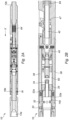
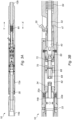
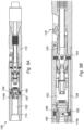
- Figures 1A , 2A and 3A are longitudinal sectional views of a downhole tool in accordance with a first embodiment of the invention in different phases of operation.
- Figure 1A is a longitudinal section through the downhole tool 10.
- the downhole tool 10 has an elongate body 12 and a mandrel 14.
- a first end 14a of the mandrel 14 is configured to be coupled to an upper tool string such as a drill string (not shown).
- the second end 14b of the mandrel is axially movably mounted in the body 12.
- a first end 12a of the body 12 surrounds a portion of mandrel 14.
- the second end 12b of the body is configured to be coupled to a lower tool string such as a drill string (not shown).
- the lower tool string may be connected to downhole tool located further downhole.
- the second end 12b of the body is designed for insertion into a downhole tubular first.
- the mandrel 14 is configured to be axially moveable in the body and is held in a first position by sheer screws 16.
- the tool body 12 comprises a cutting mechanism 18 configured to deploy knifes 20 to cut the casing.
- FIG 1B shows an enlarged view of area A-A" of Figure 1A .
- the cutting mechanism 18 comprises a plurality of knives 20 disposed circumferentially around the tool body 12.
- One knife 20 is shown in Figures 1A and 1B ).
- the knives 20 are rotatably mounted on pivot 22, best shown in Figure 1D , and are configured to move between a storage position where the knives are retracted shown in Figure 1A and an operational position where the knives are deployed shown in Figures 3A and 3B .
- the mandrel 14 has a central bore 30 which is closed at the second end 14b. At the second end 14b of the mandrel are located a first set of ports 32 and second set of ports 34. The first and second sets of ports are axially separated from one another. Ports 32 are in fluid communication with channels 32a in the mandrel 14.
- Figs 1B and 1C shows a piston 40 which is axially movably mounted in the body 12.
- the piston 40 is configured to move axially between a first position shown in Figure 1A and second position shown in Figure 3A . Although it is shown to move between a first and second position, intermediate positions may be selected.
- the piston 40 comprises a piston sleeve 42.
- the piston sleeve 42 has a first shoulder 44.
- Side 44a of shoulder 44 is configured to engage a pivot arm 28 connected to the cutting knives 20, best shown in Figure 1D . In the first mandrel position the position of the first shoulder 44 hinders the rotation of the pivot arm 28 and maintains the knives in a retracted position.
- the piston 40 has an inlet nozzle 50 to a central bore 52 which extends through the piston 40. Ports 54 extend into the central bore 52 of the piston.
- the shoulder 44 is configured to minimize the maximum cutting OD (sweep) of the knives when cutting.
- Side 44b of shoulder 44 is configured to stop the piston 40 at a set cutting OD (Sweep).
- the side 44b of shoulder 44 may be configured to stop the piston 40 by engaging with a shoulder 47 on the tool body at a set cutting outer diameter sweep.
- the maximum cutting OD may be adjusted.
- the maximum cutting OD may be adjusted by changing the position of the sleeve 42 on the piston 40.
- the sleeve is threaded attached to the piston 40 and the maximum cutting OD can be adjusted by rotating the sleeve.
- the sleeve position is secured in position by set screws 58. Alternatively, or additionally a screw may be provided that limits the amount the sleeve can be adjusted (not shown).
- the piston 40 comprises a shoulder 60.
- Shoulder 60 is configured to engage the pivot arm 28 connected to the cutting knives 20 and to pivotally move the knives 20 between a knife storage position shown in Figure 1A and an operational position shown in Figure 3A when a fluid pressure is applied to piston 40.
- the mandrel 14 is held in a first position relative to the body 12 by shear screws 16.
- the mandrel is configured to move from the first position shown in Figure 1A to a second position shown in Figure 2A .
- a first fluid flow pathway through the tool is open.
- the first pathway consists of channels 32a on the mandrel 14 in fluid communication with a bypass channel 38.
- the bypass channel 38 is in fluid communication with ports 54 on the piston 40.
- ports 32 align with ports 33 and on the tool body. Fluid that flows through ports 32 and 33 flows into the annular space which may aid in the removal of cutting and/or debris from cutting and/or drill sites.
- fluid flows through a first flow pathway in the tool and may actuate and/or control another tool located further downhole on the tool string.
- Fluid flowing through the upper tool string first flows through the first flow pathway then through bore 30 of the mandrel. Fluid flows through bore 30 through channels 32a into the bypass channel 38. The flow continues through ports 54 on the piston 40 into the bore 52.
- the fluid flows in the inner bore of the tool string and may be used to actuate at least one downstream hydraulic tool such as a drill, packer or bridge plug (not shown). Some fluid flows through ports 32 and 33 into the annular space.
- the tool 10 can be rotated on the work string and fluid may be pumped through this first pathway without actuating the cutting mechanism and deploying the knives. This may facilitate the actuation of a downstream tool to enable multiple tasks to be performed in once the tool is deployed downhole without requiring the tool to return to surface.
- Flow through the tool may control the actuation of a downstream tool such as a drill or mill and may enable cement dressing off of a cement plug prior to the casing being cut by the cutting mechanism.
- a downstream tool such as a drill or mill
- the tool may allow a high fluid flow rate to be pumped through the tool.
- the tool may also allow the transfer torque to a downstream tool such as a drill bit or mill without actuating the cutting mechanism.
- Figure 4 shows a longitudinal view of the tool in circulation mode.
- the axial load may be provided by a set down weight or hydraulic pressure.
- the axial load is provided by a set-down weight which moves the mandrel from the first axial position shown in Figure 1A to a second axial position shown in Figure 2A .
- the mandrel 14 is configured to be moved within the body 12 to a second position as shown in Figure 2A and 2B .
- the mandrel is held in the second position by spring activated keys 19 located in an internal surface of body 12 engaging with grooves 19a located on the outer surface of the mandrel.
- Figures 2A and 2B show the mandrel in the second position where the mandrel 14 closes the first pathway and opens a second pathway.
- the mandrel 14 is moved axially such that ports 32 are not aligned with ports 33 on the body preventing fluid flow from the bore 30 into the annular space.
- the channels 32a are blocked by port valve 35 and are no longer in fluid communication with the bypass channel 38.
- the ports 34 on the second end 14b of the mandrel are moved through port valve 35 into chamber 62 in the body 12.
- the piston 40 is biased in a direction X by spring 64 as shown in Figure 2A .
- the spring 64 is a compression spring.
- any spring, compressible member or resilient member may be used to bias the sleeve in a first position.
- the spring force acting on the piston provided by spring 64 in direction X maintains shoulder 44 in contact with pivot arm 28 and prevents pivot arm 28 from rotating and deploying the knives 20.
- Figures 3A and 3B show the actuation of the cutting mechanism when the mandrel in is the second position. Fluid is pumped into the tool string and flows through the second pathway to actuate the cutting mechanism.
- Fluid passes through the second pathway. Fluid flows through bore 30 of the mandrel into the chamber 62 via ports 34 on the mandrel 14.
- the chamber 62 is in fluid communication with an axially moveable restrictor assembly 66.
- the flow resistor assembly 66 has an inlet nozzle 68, a bore 70 and an outlet 72.
- the inlet nozzle 68 is configured to introduce a pressure difference in the fluid upstream of the inlet nozzle 68 and the fluid downstream of the inlet nozzle 68.
- the fluid flows through the nozzle 68 of the flow restrictor assembly 66.
- the nozzle 68 is dimensioned to provide a resistance to flow.
- the outlet 72 of flow restrictor assembly 66 is aligned and/or seated on inlet nozzle 50.
- the fluid pressure applied to the nozzle 68 is sufficient to overcome the spring force of spring 64 the flow restrictor assembly 66 and piston 40 are moved towards second end 12b of the downhole tool, shown as direction Y in Figure 3A .
- the flow resistor assembly 66 may be adjusted to stop at selected position after travelling a predetermined distance in direction Y. When the flow resistor assembly 66 stops at this selected position the outlet 72 of flow restrictor assembly 66 will not be aligned and/or seated in inlet nozzle 50. Flow will bypass the smaller nozzle 68, and will flow through the larger sleeve inlet nozzle 50. This may provide a pressure change when the knives are at a certain cutting OD (sweep) and provide an indication that the knives are deployed and/or the cut has been made.
- Movement of the piston 40 and sleeve 42 in direction Y axially moves shoulder 60 to engage and move pivot arm 28 connected to the cutting knives 20.
- the knives 20 are moved to an operational position to allow the cutting of a casing shown in Figure 3A .
- the pivot arm 28 has a slot 29 (best shown in Figure 1D ) which prevents the pivot arm impacting the sleeve when the knife is rotated to an extended position.
- the fluid pumped through the second pathway may be adjusted to control the degree of deployment of the knives 20.
- the tool and/or tool string may be rotated with the knives deployed to cut the tubular.
- the tool can be rotated when the knifes are in an operational or retracted position.
- the tool has a spline that transfer the torque in both positions.
- the tool described above may be provided with a plurality of seals. Seals may be provided along the first and/or second pathway to prevent fluid egress. Seals may be provided between the mandrel and the tool body.
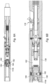
- Figures 5A, 5B , 6A and 6B show an alternative design for downhole tool 110.
- the tool comprises a ball seat 180 at end 114b of mandrel 114.
- the ball seat 180 has first series of ports 182 and a second series of ports 184 (shown best in Figure 5B ).
- the first series of ports 182 are aligned with the first pathway.
- the first fluid pathway is similar to the first fluid pathway described in relation to Figure 1A and 1B and will be understood from the description of Figure 1A and 1B above.
- the first fluid flow pathway through the tool is open.
- the first pathway consists of first series of ports 182 on the ball seat 180 which are in fluid communication with a bypass channel 138.
- the bypass channel 138 is in fluid communication with ports 154 on the piston 140.
- Fluid flows through the first flow pathway and may actuate and/or control a hydraulically operated tool located further downhole on the tool string.
- the second flow path is similar to the second fluid pathway described in relation to Figure 2A and 2B and will be understood from the description of Figure 2A and 2B above.
- the second fluid pathway consists of series of ports 184 on the ball seat 180 which are in fluid communication with chamber 162.
- the chamber 162 is in fluid communication with the cutting mechanism 118. However, during normal circulation mode the flow through the second flow path is not sufficient to actuate the cutting mechanism 118.
- Figure 6A and 6B show actuation of the cutting mechanism.
- a ball 190 is dropped in the bore of the tool string and is carried by fluid flow through bore 130 until it is retained by the ball seat 180. Once the ball 190 has engaged the ball seat 180 the ball 190 blocks ports 182 preventing fluid flow in the first pathway. Fluid is directed though ports 184 into the chamber 162 and through the second pathway.
- the actuation of the cutting mechanism is as described in relation to Figure 3A and 3B and will be understood from the description of Figure 3A and 3B .
- the mandrel is not axially moveable between a first and second position.
- first series of ports 182 are always aligned with the first pathway and the second series of ports 184 are always aligned with the second pathway.
- the mandrel and/or ball seat may be axially movable in the tool body.
- the mandrel and/or ball seat may be axially moveable when sufficient fluid pressure is applied to the ball and ball seat providing an axial force on the mandrel to move it to a second position.
- the mandrel and/or ball seat when moved to the second position the second series of ports are aligned with the second pathway.
- fluid flows through the bore of the mandrel.
- the flow passes through the first flow pathway via the series of ports and may actuate and/or control a hydraulically operated tool located further downhole on the tool string.
- a ball is dropped in the bore of the tool string and is carried by fluid flow where its retained by the ball seat. Once the ball has engaged the ball seat it blocks the first series of ports preventing fluid flow in the first flow pathway.
- the fluid pressure may act on the ball seat and when sufficient fluid pressure acts on the ball seat the mandrel and/or ball seat be axially movable to a second position in the tool body.
- the mandrel and/or ball seat in the second position uncovers a second series or ports which are in fluid communication with the second fluid path way. Subsequent fluid flow through the second fluid flow pathway actuates the cutting mechanism disposed in the second fluid flow pathway.
- the invention provides a downhole cutting tool.
- the tool comprises a tool body, a first flow pathway and a second flow pathway through the tool body.
- the tool also comprises a cutting mechanism configured to be in fluid communication with the second fluid flow pathway and a switching mechanism configured operable to control the opening of the first and/or second fluid flow pathway.
- the present invention obviates or at least mitigates disadvantages of prior art downhole tools and provides a robust, reliable and compact downhole cutting tool suitable for actuating multiple downhole tool and cutting a casing in a single trip.
- the invention enables multiple downhole operations to be performed on the same downhole trip, which normally would require at least two separate trips.
- the invention allows sufficient fluid flow to be pumped through the tool to actuate tools on the tool strings further downhole without uncontrolled actuation of the cutting tool.
- the invention allows the selective actuation of different tools on the same tools string. This may facilitate the controlled actuation of downhole tools such as drills and mills which require high flow rates on the same tool string as a casing cutter tool which requires a lower fluid flow rate.
- the invention avoids the simultaneous and/or accidental actuation of the downhole tools on the tool string.
- the downhole cutting tool has improved productivity and efficiency, and is capable of reliably performing multiple downhole operations once deployed downhole.
Landscapes
- Engineering & Computer Science (AREA)
- Life Sciences & Earth Sciences (AREA)
- Geology (AREA)
- Mining & Mineral Resources (AREA)
- Physics & Mathematics (AREA)
- Environmental & Geological Engineering (AREA)
- Fluid Mechanics (AREA)
- General Life Sciences & Earth Sciences (AREA)
- Geochemistry & Mineralogy (AREA)
- Mechanical Engineering (AREA)
- Drilling And Boring (AREA)
- Auxiliary Devices For Machine Tools (AREA)
Claims (15)
- Outil de coupe de fond de puits (10, 110) comprenant :un corps d'outil (12) ;une première voie d'écoulement à travers le corps d'outil ;une deuxième voie d'écoulement à travers le corps d'outil ;un mécanisme de coupe (18, 118) configuré pour être en communication fluidique avec la deuxième voie d'écoulement de fluide etun mécanisme de commutation ;le mécanisme de commutation comprenant un mandrin (14, 114) ayant un alésage central (30) de mandrin avec une première extrémité (14a) configurée pour être couplée à une chaîne d'outils supérieure, et un premier ensemble de canaux (32a) ou d'orifices (182) à une deuxième extrémité (14b), le mécanisme de commutation pouvant être actionné pour fermer la première voie d'écoulement ;le mécanisme de coupe (18, 118) comportant une pluralité de couteaux (20) pour couper du tubage, le corps d'outil (12) comportant une première extrémité (12a) entourant une partie du mandrin et une deuxième extrémité (12b) configurée pour être couplée à une chaîne d'outils inférieure ;l'outil de coupe de fond de puits comprenant en outre un piston (40, 140) pouvant se déplacer axialement dans une chambre (62, 162) du corps d'outil et comprenant un manchon de piston (42) avec un épaulement (44) configuré pour s'engager dans un bras pivotant (28) du mécanisme de coupe, une buse d'entrée (50) de piston vers un alésage central de piston (52) et un deuxième ensemble d'orifices (54, 154) s'étendant dans l'alésage central de piston (52) ; etun canal de dérivation (38, 138) en communication fluidique avec les orifices (54, 154) sur le piston (40, 140) ;l'outil de coupe de fond de puits pouvant être commuté par l'actionnement du mécanisme de commutation entre une première position et une deuxième position, dans lequel :
dans la première position :la première voie d'écoulement est ouverte, et l'écoulement de fluide provenant de la chaîne d'outils supérieure pénètre dans l'alésage central (30) de mandrin, passe à travers le premier ensemble de canaux (32a) ou d'orifices (182) dans le canal de dérivation (38, 138) pour pénétrer dans le deuxième ensemble d'orifices (54, 154) s'étendant dans l'alésage central de piston (52) et jusqu'à un alésage intérieur de la chaîne d'outils inférieure, et les couteaux (20) sont rétractés et maintenus dans une position de stockage ; etdans la deuxième position :
la deuxième voie d'écoulement est ouverte, la première voie d'écoulement est fermée car le canal de dérivation (38, 138) est fermé, et un écoulement de fluide provenant de la chaîne d'outils supérieure pénètre dans l'alésage central (30) de mandrin, passe à travers un troisième ensemble d'orifices (34, 184) dans la chambre (62, 162) pour pénétrer dans la buse d'entrée (50) jusqu'à l'alésage central de piston (52) et déplace le piston (40) pour engager un deuxième épaulement (60) avec le bras pivotant (28) pour faire tourner les couteaux (20) vers une position opérationnelle étendue pour couper du tubage. - Outil de coupe de fond de puits selon la revendication 1, dans lequel : le mandrin (14) est axialement mobile dans le corps d'outil ; la première voie d'écoulement passe par l'alésage central (30), le premier ensemble de canaux (32a) dans le mandrin (14), le canal de dérivation (38), le deuxième ensemble d'orifices (54) et l'alésage central de piston (52) ; l'outil de coupe de fond de puits inclut des vis de cisaillement (16) pour maintenir le mandrin (14) par rapport au corps d'outil (12) dans la première position ; et, le poids est abaissé pour déplacer le mandrin (14) par rapport au corps d'outil (12) dans la deuxième position.
- Outil de coupe de fond de puits selon la revendication 1, dans lequel : le mandrin (14) est déplaçable axialement dans le corps d'outil; la première voie d'écoulement passe par l'alésage central (30), le premier ensemble de canaux (32a) dans le mandrin (14), le canal de dérivation (38), le deuxième ensemble d'orifices (54) et l'alésage central de piston (52) ; l'outil de coupe de fond de puits inclut un siège de bille de chute à la deuxième extrémité (14b) du mandrin (14) et une bille de chute est utilisée pour déplacer le mandrin (14) par rapport au corps d'outil (12) dans la deuxième position.
- Outil de coupe de fond de puits selon la revendication 1, dans lequel l'outil de coupe de fond de puits inclut un siège de bille de chute (180) à la deuxième extrémité (114b) du mandrin (114) ; le siège de bille de chute (180) incluant le premier ensemble d'orifices (182) en communication fluidique avec le canal de dérivation (138) dans la première position ; le troisième ensemble d'orifices (184) dans le siège de bille (180) est en communication fluidique avec la chambre (162) ; et une bille de chute (190) est retenue dans le siège de bille de chute (180) pour faire passer l'outil de coupe de fond de puits entre la première et la deuxième position.
- Outil de coupe de fond de puits selon l'une quelconque des revendications précédentes, dans lequel l'outil de coupe de fond de puits comprend en outre un moyen de sollicitation (64) pour solliciter le piston dans la première position, le moyen de sollicitation est choisi dans un groupe comprenant : un ressort, un ressort de compression, un élément compressible et un élément résilient.
- Outil de coupe de fond de puits selon l'une quelconque des revendications précédentes, dans lequel le mécanisme de coupe comprend en outre un ensemble de restriction d'écoulement débit (60) déplaçable axialement dans le corps d'outil et situé dans la chambre entre la deuxième extrémité du mandrin et le piston, l'ensemble de restriction découlement comprend une buse d'entrée (68), un alésage (70) et une sortie (72) dans laquelle la sortie est configurée pour se loger dans la buse d'entrée du piston et dans laquelle la buse d'entrée est plus petite que la buse d'entrée du piston.
- Outil de coupe de fond de puits selon l'une quelconque des revendications précédentes, dans lequel le corps d'outil comporte une cannelure de manière à transférer le couple à travers l'outil de coupe de fond de puits dans la première et la deuxième position du mandrin.
- Outil de coupe de fond de puits selon l'une quelconque des revendications précédentes, dans lequel un outil de fond de puits actionné hydrauliquement est couplé à la chaîne d'outils inférieure.
- Outil de coupe de fond de puits selon la revendication 8, dans lequel l'outil de fond de puits actionné hydrauliquement est choisi dans un groupe comprenant : foret, fraise, packer, bouchon de pont, déconnexions hydrauliques, fouet, outils de réglage hydrauliques et pistolet de perforation.
- Procédé d'exploitation d'un outil de coupe de fond de puits et d'un outil de fond de puits à commande hydraulique sur une seule descente de fond de puits comprenant les étapes consistant à :fournir un outil de coupe de fond de puits selon la revendication 8 ;faire rentrer la chaîne d'outils dans du tubage avec l'outil de coupe de fond de puits dans la première position ;pomper du fluide à travers l'outil de coupe de fond de puits via la première voie d'écoulement pour actionner l'outil de fond à commande hydraulique ;faire passer l'outil de coupe de fond de puits dans la deuxième position ;pomper du fluide à travers l'outil de coupe de fond de puits via la deuxième voie d'écoulement pour étendre les couteaux et ainsi couper le tubage.
- Procédé d'utilisation d'un outil de coupe de fond de puits et d'un outil de fond de puits à commande hydraulique sur une seule descente de fond de puits selon la revendication 10, dans lequel le procédé comprend l'application d'un poids sur l'outil de coupe de fond de puits pour le faire passer à la deuxième position.
- Procédé d'utilisation d'un outil de coupe de fond de puits et d'un outil de fond de puits à commande hydraulique sur une seule descente de puits selon la revendication 10, dans lequel le procédé comprend le fait de faire chuter une bille à travers le chaîne d'outils pour faire passer l'outil de coupe de fond de puits dans la deuxième position.
- Procédé d'utilisation d'un outil de coupe de fond de puits et d'un outil de fond de puits à commande hydraulique sur une seule descente de puits selon l'une quelconque des revendications 10 à 12, dans lequel le procédé comprend la rotation de l'outil de coupe de fond de puits pendant que les couteaux sont déployés pour couper le tubage.
- Procédé d'exploitation d'un outil de coupe de fond de puits et d'un outil de fond de puits à commande hydraulique sur une seule descente de puits selon l'une quelconque des revendications 10 à 13, dans lequel le procédé comprend la coupe du tubage par rotation de la chaîne d'outils.
- Procédé d'utilisation d'un outil de coupe de fond de puits selon l'une quelconque des revendications 10 à 14, dans lequel l'outil de fond de puits à commande hydraulique est une foreuse et l'actionnement de la foreuse est utilisé pour enlever un bouchon de ciment avant de couper le tubage.
Applications Claiming Priority (2)
| Application Number | Priority Date | Filing Date | Title |
|---|---|---|---|
| GB1615222.5A GB2553547B (en) | 2016-09-07 | 2016-09-07 | Downhole tool and method of use |
| PCT/GB2017/052588 WO2018046907A1 (fr) | 2016-09-07 | 2017-09-06 | Outil de coupe de fond de trou et procédé d'utilisation |
Publications (2)
| Publication Number | Publication Date |
|---|---|
| EP3510239A1 EP3510239A1 (fr) | 2019-07-17 |
| EP3510239B1 true EP3510239B1 (fr) | 2024-09-04 |
Family
ID=57139752
Family Applications (1)
| Application Number | Title | Priority Date | Filing Date |
|---|---|---|---|
| EP17767878.6A Active EP3510239B1 (fr) | 2016-09-07 | 2017-09-06 | Outil de coupe de fond de trou et procédé d'utilisation |
Country Status (8)
| Country | Link |
|---|---|
| US (1) | US10844677B2 (fr) |
| EP (1) | EP3510239B1 (fr) |
| AU (1) | AU2017322532A1 (fr) |
| BR (1) | BR112019004528A2 (fr) |
| CA (1) | CA3034770A1 (fr) |
| DK (1) | DK3510239T3 (fr) |
| GB (1) | GB2553547B (fr) |
| WO (1) | WO2018046907A1 (fr) |
Families Citing this family (9)
| Publication number | Priority date | Publication date | Assignee | Title |
|---|---|---|---|---|
| US10458196B2 (en) | 2017-03-09 | 2019-10-29 | Weatherford Technology Holdings, Llc | Downhole casing pulling tool |
| US11248428B2 (en) | 2019-02-07 | 2022-02-15 | Weatherford Technology Holdings, Llc | Wellbore apparatus for setting a downhole tool |
| CN115707852B (zh) * | 2021-08-18 | 2024-12-27 | 中国石油天然气股份有限公司 | 井下段铣工具及方法 |
| GB202112201D0 (en) * | 2021-08-26 | 2021-10-13 | Ardyne Holdings Ltd | Improvements in or relating to well abandonment and slot recovery |
| US11879307B2 (en) * | 2022-02-10 | 2024-01-23 | Baker Hughes Oilfield Operations Llc | Object carrier, tool, method, and system |
| US11952861B2 (en) * | 2022-03-31 | 2024-04-09 | Schlumberger Technology Corporation | Methodology and system having downhole universal actuator |
| US12270277B2 (en) | 2022-03-31 | 2025-04-08 | Schlumberger Technology Corporation | Methodology and system for electronic control and acquisition of downhole valve |
| US11993991B2 (en) | 2022-03-31 | 2024-05-28 | Schlumberger Technology Corporation | System and method for electronically controlling downhole valve system |
| US11933141B2 (en) * | 2022-06-08 | 2024-03-19 | Halliburton Energy Services, Inc. | Multiple cycle deployable and retractable downhole scraper or brush |
Family Cites Families (31)
| Publication number | Priority date | Publication date | Assignee | Title |
|---|---|---|---|---|
| US3425500A (en) | 1966-11-25 | 1969-02-04 | Benjamin H Fuchs | Expandable underreamer |
| US6920944B2 (en) | 2000-06-27 | 2005-07-26 | Halliburton Energy Services, Inc. | Apparatus and method for drilling and reaming a borehole |
| US6131675A (en) | 1998-09-08 | 2000-10-17 | Baker Hughes Incorporated | Combination mill and drill bit |
| US6378632B1 (en) | 1998-10-30 | 2002-04-30 | Smith International, Inc. | Remotely operable hydraulic underreamer |
| US6289999B1 (en) | 1998-10-30 | 2001-09-18 | Smith International, Inc. | Fluid flow control devices and methods for selective actuation of valves and hydraulic drilling tools |
| US6732817B2 (en) | 2002-02-19 | 2004-05-11 | Smith International, Inc. | Expandable underreamer/stabilizer |
| US6929076B2 (en) | 2002-10-04 | 2005-08-16 | Security Dbs Nv/Sa | Bore hole underreamer having extendible cutting arms |
| AU2004287892A1 (en) | 2003-11-05 | 2005-05-19 | Drilling Solutions Pty Ltd | Actuating mechanism |
| US7757787B2 (en) | 2006-01-18 | 2010-07-20 | Smith International, Inc. | Drilling and hole enlargement device |
| WO2008024793A1 (fr) | 2006-08-21 | 2008-02-28 | Weatherford/Lamb, Inc. | Procédé de diagraphie après forage |
| US7681665B2 (en) | 2008-03-04 | 2010-03-23 | Smith International, Inc. | Downhole hydraulic control system |
| US8540035B2 (en) | 2008-05-05 | 2013-09-24 | Weatherford/Lamb, Inc. | Extendable cutting tools for use in a wellbore |
| US7954564B2 (en) | 2008-07-24 | 2011-06-07 | Smith International, Inc. | Placement of cutting elements on secondary cutting structures of drilling tool assemblies |
| US20100193250A1 (en) | 2009-01-30 | 2010-08-05 | Tesco Corporation | Cutting Structure for Casing Drilling Underreamer |
| US8776912B2 (en) | 2009-05-01 | 2014-07-15 | Smith International, Inc. | Secondary cutting structure |
| WO2011041562A2 (fr) | 2009-09-30 | 2011-04-07 | Baker Hughes Incorporated | Appareil télécommandé pour applications de fond de puits et procédés d'exploitation |
| US8381837B2 (en) | 2010-03-26 | 2013-02-26 | Smith International, Inc. | Downhole tool deactivation and re-activation |
| EP2572070A4 (fr) * | 2010-05-21 | 2015-11-18 | Smith International | Actionnement hydraulique d'ensemble outil de fond de trou |
| CN103261560A (zh) | 2010-11-08 | 2013-08-21 | 贝克休斯公司 | 用在地下井眼中的具有可扩张元件的工具以及相关方法 |
| US8978783B2 (en) | 2011-05-26 | 2015-03-17 | Smith International, Inc. | Jet arrangement on an expandable downhole tool |
| US8960333B2 (en) | 2011-12-15 | 2015-02-24 | Baker Hughes Incorporated | Selectively actuating expandable reamers and related methods |
| US20130206401A1 (en) * | 2012-02-13 | 2013-08-15 | Smith International, Inc. | Actuation system and method for a downhole tool |
| JP5845554B2 (ja) | 2012-07-04 | 2016-01-20 | ▲ホア▼▲ウェイ▼技術有限公司 | マルチメディアデータを記録するための方法、デバイス、およびシステム |
| CA2896652C (fr) | 2013-01-25 | 2018-06-05 | Halliburton Energy Services, Inc. | Actionnement hydraulique d'outil d'ensemble de fond de trou mecanique |
| CA2912437C (fr) | 2013-05-13 | 2019-03-05 | Weatherford Technology Holdings, Llc | Procede et appareil permettant de faire fonctionner un outil de fond de trou |
| US10156097B2 (en) | 2013-06-09 | 2018-12-18 | Smith International, Inc. | Downhole tool for increasing a wellbore diameter |
| WO2015114407A1 (fr) * | 2014-01-31 | 2015-08-06 | Tercel Ip Limited | Outil de fond de trou et procédé d'exploitation d'un tel outil de fond de trou |
| WO2015114408A1 (fr) | 2014-01-31 | 2015-08-06 | Tercel Ip Limited | Outil de fond de trou et procédé d'exploitation de cet outil de fond de trou |
| US9173526B2 (en) | 2014-03-12 | 2015-11-03 | Donald P. Berry | Potato chip lifter |
| FR3022290B1 (fr) | 2014-06-16 | 2019-06-14 | Drillstar Industries | Outil extensible pour un forage |
| GB201516452D0 (en) * | 2015-09-16 | 2015-10-28 | Telfer George | Downhole cutting and pulling tool and method of use |
-
2016
- 2016-09-07 GB GB1615222.5A patent/GB2553547B/en active Active
-
2017
- 2017-09-06 EP EP17767878.6A patent/EP3510239B1/fr active Active
- 2017-09-06 DK DK17767878.6T patent/DK3510239T3/da active
- 2017-09-06 US US16/329,109 patent/US10844677B2/en active Active
- 2017-09-06 WO PCT/GB2017/052588 patent/WO2018046907A1/fr not_active Ceased
- 2017-09-06 CA CA3034770A patent/CA3034770A1/fr not_active Abandoned
- 2017-09-06 BR BR112019004528A patent/BR112019004528A2/pt not_active Application Discontinuation
- 2017-09-06 AU AU2017322532A patent/AU2017322532A1/en not_active Abandoned
Also Published As
| Publication number | Publication date |
|---|---|
| WO2018046907A1 (fr) | 2018-03-15 |
| US20190226294A1 (en) | 2019-07-25 |
| DK3510239T3 (da) | 2024-09-30 |
| GB2553547B (en) | 2019-12-04 |
| US10844677B2 (en) | 2020-11-24 |
| EP3510239A1 (fr) | 2019-07-17 |
| GB201615222D0 (en) | 2016-10-19 |
| AU2017322532A1 (en) | 2019-03-14 |
| BR112019004528A2 (pt) | 2019-05-28 |
| GB2553547A (en) | 2018-03-14 |
| CA3034770A1 (fr) | 2018-03-15 |
Similar Documents
| Publication | Publication Date | Title |
|---|---|---|
| EP3510239B1 (fr) | Outil de coupe de fond de trou et procédé d'utilisation | |
| CA2524189C (fr) | Outil de fond possedant des elements extensibles radialement | |
| US7823663B2 (en) | Expandable reamer | |
| US8955597B2 (en) | Method and system for abandoning a borehole | |
| AU2014266983B2 (en) | Apparatus and method for controlling a downhole device | |
| CA2568053C (fr) | Mecanisme a rotule permettant de commander le fonctionnement d'un outil de fond de trou | |
| US10487602B2 (en) | Hydraulic control of downhole tools | |
| US20150014061A1 (en) | Hydraulic actuation of a downhole tool assembly | |
| WO2014138019A1 (fr) | Ensembles d'actionnement, outils actionnés hydrauliquement pour l'utilisation dans des trous de forage souterrains comprenant des ensembles d'actionnement et procédés associés | |
| GB2344122A (en) | Fluid flow control devices and methods for selective actuation of valves and hydraulic drilling tools | |
| GB2428057A (en) | Single trip milling and drilling assembly and method | |
| US11808099B2 (en) | Apparatuses and methods for locating and shifting a downhole flow control member | |
| NO349443B1 (en) | Downhole tool, downhole milling tool, and method for milling a casing string in a wellbore | |
| EP2464817B1 (fr) | Actionneur et procédé | |
| US9840891B2 (en) | Electromechanical shifting tool | |
| US20150322725A1 (en) | Hydraulically locked tool | |
| GB2475167A (en) | Under reamer | |
| GB2381550A (en) | Fluid flow control devices and methods for selective actuation of valves and hydraulic drilling tools |
Legal Events
| Date | Code | Title | Description |
|---|---|---|---|
| STAA | Information on the status of an ep patent application or granted ep patent |
Free format text: STATUS: UNKNOWN |
|
| STAA | Information on the status of an ep patent application or granted ep patent |
Free format text: STATUS: THE INTERNATIONAL PUBLICATION HAS BEEN MADE |
|
| PUAI | Public reference made under article 153(3) epc to a published international application that has entered the european phase |
Free format text: ORIGINAL CODE: 0009012 |
|
| STAA | Information on the status of an ep patent application or granted ep patent |
Free format text: STATUS: REQUEST FOR EXAMINATION WAS MADE |
|
| 17P | Request for examination filed |
Effective date: 20190307 |
|
| AK | Designated contracting states |
Kind code of ref document: A1 Designated state(s): AL AT BE BG CH CY CZ DE DK EE ES FI FR GB GR HR HU IE IS IT LI LT LU LV MC MK MT NL NO PL PT RO RS SE SI SK SM TR |
|
| AX | Request for extension of the european patent |
Extension state: BA ME |
|
| DAV | Request for validation of the european patent (deleted) | ||
| DAX | Request for extension of the european patent (deleted) | ||
| STAA | Information on the status of an ep patent application or granted ep patent |
Free format text: STATUS: EXAMINATION IS IN PROGRESS |
|
| 17Q | First examination report despatched |
Effective date: 20220926 |
|
| GRAP | Despatch of communication of intention to grant a patent |
Free format text: ORIGINAL CODE: EPIDOSNIGR1 |
|
| STAA | Information on the status of an ep patent application or granted ep patent |
Free format text: STATUS: GRANT OF PATENT IS INTENDED |
|
| RIC1 | Information provided on ipc code assigned before grant |
Ipc: E21B 10/32 20060101ALI20240425BHEP Ipc: E21B 34/14 20060101ALI20240425BHEP Ipc: E21B 23/04 20060101ALI20240425BHEP Ipc: E21B 29/00 20060101AFI20240425BHEP |
|
| INTG | Intention to grant announced |
Effective date: 20240528 |
|
| GRAS | Grant fee paid |
Free format text: ORIGINAL CODE: EPIDOSNIGR3 |
|
| GRAA | (expected) grant |
Free format text: ORIGINAL CODE: 0009210 |
|
| STAA | Information on the status of an ep patent application or granted ep patent |
Free format text: STATUS: THE PATENT HAS BEEN GRANTED |
|
| RBV | Designated contracting states (corrected) |
Designated state(s): AL AT BE BG CH CY CZ DE DK EE ES FI FR GR HR HU IE IS IT LI LT LU LV MC MK MT NL NO PL PT RO RS SE SI SK SM TR |
|
| AK | Designated contracting states |
Kind code of ref document: B1 Designated state(s): AL AT BE BG CH CY CZ DE DK EE ES FI FR GR HR HU IE IS IT LI LT LU LV MC MK MT NL NO PL PT RO RS SE SI SK SM TR |
|
| REG | Reference to a national code |
Ref country code: CH Ref legal event code: EP |
|
| REG | Reference to a national code |
Ref country code: IE Ref legal event code: FG4D |
|
| REG | Reference to a national code |
Ref country code: DE Ref legal event code: R096 Ref document number: 602017084646 Country of ref document: DE |
|
| REG | Reference to a national code |
Ref country code: DK Ref legal event code: T3 Effective date: 20240923 |
|
| REG | Reference to a national code |
Ref country code: NL Ref legal event code: FP |
|
| REG | Reference to a national code |
Ref country code: LT Ref legal event code: MG9D |
|
| PG25 | Lapsed in a contracting state [announced via postgrant information from national office to epo] |
Ref country code: PL Free format text: LAPSE BECAUSE OF FAILURE TO SUBMIT A TRANSLATION OF THE DESCRIPTION OR TO PAY THE FEE WITHIN THE PRESCRIBED TIME-LIMIT Effective date: 20240904 Ref country code: GR Free format text: LAPSE BECAUSE OF FAILURE TO SUBMIT A TRANSLATION OF THE DESCRIPTION OR TO PAY THE FEE WITHIN THE PRESCRIBED TIME-LIMIT Effective date: 20241205 Ref country code: FI Free format text: LAPSE BECAUSE OF FAILURE TO SUBMIT A TRANSLATION OF THE DESCRIPTION OR TO PAY THE FEE WITHIN THE PRESCRIBED TIME-LIMIT Effective date: 20240904 |
|
| PG25 | Lapsed in a contracting state [announced via postgrant information from national office to epo] |
Ref country code: BG Free format text: LAPSE BECAUSE OF FAILURE TO SUBMIT A TRANSLATION OF THE DESCRIPTION OR TO PAY THE FEE WITHIN THE PRESCRIBED TIME-LIMIT Effective date: 20240904 |
|
| PG25 | Lapsed in a contracting state [announced via postgrant information from national office to epo] |
Ref country code: LV Free format text: LAPSE BECAUSE OF FAILURE TO SUBMIT A TRANSLATION OF THE DESCRIPTION OR TO PAY THE FEE WITHIN THE PRESCRIBED TIME-LIMIT Effective date: 20240904 |
|
| PG25 | Lapsed in a contracting state [announced via postgrant information from national office to epo] |
Ref country code: HR Free format text: LAPSE BECAUSE OF FAILURE TO SUBMIT A TRANSLATION OF THE DESCRIPTION OR TO PAY THE FEE WITHIN THE PRESCRIBED TIME-LIMIT Effective date: 20240904 |
|
| PG25 | Lapsed in a contracting state [announced via postgrant information from national office to epo] |
Ref country code: ES Free format text: LAPSE BECAUSE OF FAILURE TO SUBMIT A TRANSLATION OF THE DESCRIPTION OR TO PAY THE FEE WITHIN THE PRESCRIBED TIME-LIMIT Effective date: 20240904 |
|
| PG25 | Lapsed in a contracting state [announced via postgrant information from national office to epo] |
Ref country code: PL Free format text: LAPSE BECAUSE OF FAILURE TO SUBMIT A TRANSLATION OF THE DESCRIPTION OR TO PAY THE FEE WITHIN THE PRESCRIBED TIME-LIMIT Effective date: 20240904 Ref country code: LV Free format text: LAPSE BECAUSE OF FAILURE TO SUBMIT A TRANSLATION OF THE DESCRIPTION OR TO PAY THE FEE WITHIN THE PRESCRIBED TIME-LIMIT Effective date: 20240904 Ref country code: HR Free format text: LAPSE BECAUSE OF FAILURE TO SUBMIT A TRANSLATION OF THE DESCRIPTION OR TO PAY THE FEE WITHIN THE PRESCRIBED TIME-LIMIT Effective date: 20240904 Ref country code: GR Free format text: LAPSE BECAUSE OF FAILURE TO SUBMIT A TRANSLATION OF THE DESCRIPTION OR TO PAY THE FEE WITHIN THE PRESCRIBED TIME-LIMIT Effective date: 20241205 Ref country code: FI Free format text: LAPSE BECAUSE OF FAILURE TO SUBMIT A TRANSLATION OF THE DESCRIPTION OR TO PAY THE FEE WITHIN THE PRESCRIBED TIME-LIMIT Effective date: 20240904 Ref country code: ES Free format text: LAPSE BECAUSE OF FAILURE TO SUBMIT A TRANSLATION OF THE DESCRIPTION OR TO PAY THE FEE WITHIN THE PRESCRIBED TIME-LIMIT Effective date: 20240904 Ref country code: BG Free format text: LAPSE BECAUSE OF FAILURE TO SUBMIT A TRANSLATION OF THE DESCRIPTION OR TO PAY THE FEE WITHIN THE PRESCRIBED TIME-LIMIT Effective date: 20240904 |
|
| REG | Reference to a national code |
Ref country code: AT Ref legal event code: MK05 Ref document number: 1720590 Country of ref document: AT Kind code of ref document: T Effective date: 20240904 |
|
| PG25 | Lapsed in a contracting state [announced via postgrant information from national office to epo] |
Ref country code: PT Free format text: LAPSE BECAUSE OF FAILURE TO SUBMIT A TRANSLATION OF THE DESCRIPTION OR TO PAY THE FEE WITHIN THE PRESCRIBED TIME-LIMIT Effective date: 20250106 Ref country code: IS Free format text: LAPSE BECAUSE OF FAILURE TO SUBMIT A TRANSLATION OF THE DESCRIPTION OR TO PAY THE FEE WITHIN THE PRESCRIBED TIME-LIMIT Effective date: 20250104 |
|
| PG25 | Lapsed in a contracting state [announced via postgrant information from national office to epo] |
Ref country code: SM Free format text: LAPSE BECAUSE OF FAILURE TO SUBMIT A TRANSLATION OF THE DESCRIPTION OR TO PAY THE FEE WITHIN THE PRESCRIBED TIME-LIMIT Effective date: 20240904 Ref country code: RO Free format text: LAPSE BECAUSE OF FAILURE TO SUBMIT A TRANSLATION OF THE DESCRIPTION OR TO PAY THE FEE WITHIN THE PRESCRIBED TIME-LIMIT Effective date: 20240904 |
|
| PG25 | Lapsed in a contracting state [announced via postgrant information from national office to epo] |
Ref country code: EE Free format text: LAPSE BECAUSE OF FAILURE TO SUBMIT A TRANSLATION OF THE DESCRIPTION OR TO PAY THE FEE WITHIN THE PRESCRIBED TIME-LIMIT Effective date: 20240904 Ref country code: AT Free format text: LAPSE BECAUSE OF FAILURE TO SUBMIT A TRANSLATION OF THE DESCRIPTION OR TO PAY THE FEE WITHIN THE PRESCRIBED TIME-LIMIT Effective date: 20240904 |
|
| PG25 | Lapsed in a contracting state [announced via postgrant information from national office to epo] |
Ref country code: CZ Free format text: LAPSE BECAUSE OF FAILURE TO SUBMIT A TRANSLATION OF THE DESCRIPTION OR TO PAY THE FEE WITHIN THE PRESCRIBED TIME-LIMIT Effective date: 20240904 |
|
| PG25 | Lapsed in a contracting state [announced via postgrant information from national office to epo] |
Ref country code: SK Free format text: LAPSE BECAUSE OF FAILURE TO SUBMIT A TRANSLATION OF THE DESCRIPTION OR TO PAY THE FEE WITHIN THE PRESCRIBED TIME-LIMIT Effective date: 20240904 Ref country code: IT Free format text: LAPSE BECAUSE OF FAILURE TO SUBMIT A TRANSLATION OF THE DESCRIPTION OR TO PAY THE FEE WITHIN THE PRESCRIBED TIME-LIMIT Effective date: 20240904 |
|
| REG | Reference to a national code |
Ref country code: CH Ref legal event code: PL |
|
| PG25 | Lapsed in a contracting state [announced via postgrant information from national office to epo] |
Ref country code: LU Free format text: LAPSE BECAUSE OF NON-PAYMENT OF DUE FEES Effective date: 20240906 |
|
| REG | Reference to a national code |
Ref country code: DE Ref legal event code: R097 Ref document number: 602017084646 Country of ref document: DE |
|
| PG25 | Lapsed in a contracting state [announced via postgrant information from national office to epo] |
Ref country code: RS Free format text: LAPSE BECAUSE OF FAILURE TO SUBMIT A TRANSLATION OF THE DESCRIPTION OR TO PAY THE FEE WITHIN THE PRESCRIBED TIME-LIMIT Effective date: 20240904 |
|
| PG25 | Lapsed in a contracting state [announced via postgrant information from national office to epo] |
Ref country code: MC Free format text: LAPSE BECAUSE OF FAILURE TO SUBMIT A TRANSLATION OF THE DESCRIPTION OR TO PAY THE FEE WITHIN THE PRESCRIBED TIME-LIMIT Effective date: 20240904 |
|
| REG | Reference to a national code |
Ref country code: BE Ref legal event code: MM Effective date: 20240930 |
|
| PLBE | No opposition filed within time limit |
Free format text: ORIGINAL CODE: 0009261 |
|
| STAA | Information on the status of an ep patent application or granted ep patent |
Free format text: STATUS: NO OPPOSITION FILED WITHIN TIME LIMIT |
|
| PG25 | Lapsed in a contracting state [announced via postgrant information from national office to epo] |
Ref country code: BE Free format text: LAPSE BECAUSE OF NON-PAYMENT OF DUE FEES Effective date: 20240930 |
|
| PG25 | Lapsed in a contracting state [announced via postgrant information from national office to epo] |
Ref country code: CH Free format text: LAPSE BECAUSE OF NON-PAYMENT OF DUE FEES Effective date: 20240930 |
|
| PG25 | Lapsed in a contracting state [announced via postgrant information from national office to epo] |
Ref country code: IE Free format text: LAPSE BECAUSE OF NON-PAYMENT OF DUE FEES Effective date: 20240906 |
|
| 26N | No opposition filed |
Effective date: 20250605 |
|
| PGFP | Annual fee paid to national office [announced via postgrant information from national office to epo] |
Ref country code: NL Payment date: 20250704 Year of fee payment: 9 |
|
| PG25 | Lapsed in a contracting state [announced via postgrant information from national office to epo] |
Ref country code: SE Free format text: LAPSE BECAUSE OF FAILURE TO SUBMIT A TRANSLATION OF THE DESCRIPTION OR TO PAY THE FEE WITHIN THE PRESCRIBED TIME-LIMIT Effective date: 20240904 |
|
| PGFP | Annual fee paid to national office [announced via postgrant information from national office to epo] |
Ref country code: DE Payment date: 20250702 Year of fee payment: 9 Ref country code: DK Payment date: 20250911 Year of fee payment: 9 |
|
| PGFP | Annual fee paid to national office [announced via postgrant information from national office to epo] |
Ref country code: NO Payment date: 20250909 Year of fee payment: 9 |
|
| PG25 | Lapsed in a contracting state [announced via postgrant information from national office to epo] |
Ref country code: FR Free format text: LAPSE BECAUSE OF NON-PAYMENT OF DUE FEES Effective date: 20241104 |
|
| PG25 | Lapsed in a contracting state [announced via postgrant information from national office to epo] |
Ref country code: CY Free format text: LAPSE BECAUSE OF FAILURE TO SUBMIT A TRANSLATION OF THE DESCRIPTION OR TO PAY THE FEE WITHIN THE PRESCRIBED TIME-LIMIT; INVALID AB INITIO Effective date: 20170906 |
|
| PG25 | Lapsed in a contracting state [announced via postgrant information from national office to epo] |
Ref country code: HU Free format text: LAPSE BECAUSE OF FAILURE TO SUBMIT A TRANSLATION OF THE DESCRIPTION OR TO PAY THE FEE WITHIN THE PRESCRIBED TIME-LIMIT; INVALID AB INITIO Effective date: 20170906 |