EP3510280B1 - Assemblage de transport - Google Patents
Assemblage de transport Download PDFInfo
- Publication number
- EP3510280B1 EP3510280B1 EP17792010.5A EP17792010A EP3510280B1 EP 3510280 B1 EP3510280 B1 EP 3510280B1 EP 17792010 A EP17792010 A EP 17792010A EP 3510280 B1 EP3510280 B1 EP 3510280B1
- Authority
- EP
- European Patent Office
- Prior art keywords
- load
- transport assembly
- positioning beam
- transport
- positioning
- Prior art date
- Legal status (The legal status is an assumption and is not a legal conclusion. Google has not performed a legal analysis and makes no representation as to the accuracy of the status listed.)
- Active
Links
Images




Classifications
-
- F—MECHANICAL ENGINEERING; LIGHTING; HEATING; WEAPONS; BLASTING
- F03—MACHINES OR ENGINES FOR LIQUIDS; WIND, SPRING, OR WEIGHT MOTORS; PRODUCING MECHANICAL POWER OR A REACTIVE PROPULSIVE THRUST, NOT OTHERWISE PROVIDED FOR
- F03D—WIND MOTORS
- F03D13/00—Assembly, mounting or commissioning of wind motors; Arrangements specially adapted for transporting wind motor components
- F03D13/40—Arrangements or methods specially adapted for transporting wind motor components
-
- B—PERFORMING OPERATIONS; TRANSPORTING
- B60—VEHICLES IN GENERAL
- B60P—VEHICLES ADAPTED FOR LOAD TRANSPORTATION OR TO TRANSPORT, TO CARRY, OR TO COMPRISE SPECIAL LOADS OR OBJECTS
- B60P3/00—Vehicles adapted to transport, to carry or to comprise special loads or objects
-
- F—MECHANICAL ENGINEERING; LIGHTING; HEATING; WEAPONS; BLASTING
- F05—INDEXING SCHEMES RELATING TO ENGINES OR PUMPS IN VARIOUS SUBCLASSES OF CLASSES F01-F04
- F05B—INDEXING SCHEME RELATING TO WIND, SPRING, WEIGHT, INERTIA OR LIKE MOTORS, TO MACHINES OR ENGINES FOR LIQUIDS COVERED BY SUBCLASSES F03B, F03D AND F03G
- F05B2260/00—Function
- F05B2260/02—Transport, e.g. specific adaptations or devices for conveyance
-
- Y—GENERAL TAGGING OF NEW TECHNOLOGICAL DEVELOPMENTS; GENERAL TAGGING OF CROSS-SECTIONAL TECHNOLOGIES SPANNING OVER SEVERAL SECTIONS OF THE IPC; TECHNICAL SUBJECTS COVERED BY FORMER USPC CROSS-REFERENCE ART COLLECTIONS [XRACs] AND DIGESTS
- Y02—TECHNOLOGIES OR APPLICATIONS FOR MITIGATION OR ADAPTATION AGAINST CLIMATE CHANGE
- Y02E—REDUCTION OF GREENHOUSE GAS [GHG] EMISSIONS, RELATED TO ENERGY GENERATION, TRANSMISSION OR DISTRIBUTION
- Y02E10/00—Energy generation through renewable energy sources
- Y02E10/70—Wind energy
- Y02E10/72—Wind turbines with rotation axis in wind direction
Definitions
- the invention describes a transport assembly for securing a large heavy load to a load platform during a transport manoeuvre.
- the invention further describes a method of securing a large heavy load on a load platform during a transport manoeuvre.
- Such load transfer manoeuvres can become expensive when it is necessary to move loads that have irregular shapes in addition to being very heavy.
- the different parts of a wind turbine can have different shapes and different weights.
- a nacelle unit of a large 10 - 20 MW generator can weigh in the region of several hundred metric tonnes, for example. Its transport is made difficult owing to its irregular shape and to the lack of external features which could be used to hold it during transport. Transport of such an irregular heavy object can be made even more difficult if its centre of gravity is offset from its geometrical centre. It is necessary to ensure that the load and the transport equipment are not damaged during a transport manoeuvre.
- an irregularly shaped object may exert bending moments on the loading platform, and may damage the transport equipment. A poorly or inadequately supported load may itself be damaged during transport by such bending moments.
- a prior art transport assembly is known from EP2395240A1 .
- the transport assembly is intended for use in the transport of a large heavy load, and comprises a frame unit realized to fit over a load platform of a transport vehicle; one or more first load-positioning beams, each realized to span a single frame unit and/or one or more second load-positioning beams, each realized to span a pair of adjacent frame units; and at least one part adapter realized to engage with a load-positioning beam and to engage with the load.
- An advantage of the transport assembly according to the invention is that it allows a very heavy load to be securely held in place on a load platform of a transport vehicle in such a way that the load is evenly distributed over the load platform. Furthermore, the modular nature of the transport assembly allows various different kinds of load - with different dimensions and different weights - to be transported using the same transport assembly. In other words, assembly configuration of the inventive transport assembly can easily be adjusted for the transport of one kind of load, and then later adjusted again for the transport of a different load. Even for loads with irregular shapes, the transport assembly allows a balanced and even load distribution. The inventive transport assembly effectively prevents bending moments that would otherwise place stress on the transport equipment.
- the method of securing a large heavy load on a load platform during a transport manoeuvre comprises the steps of arranging a single frame unit of such a transport assembly over the load platform and then arranging at least one first load-positioning beam across the single frame unit; or arranging two frame units of such a transport assembly over a pair of adjacent load platforms, and arranging at least one second load-positioning beam across the frame units.
- a part adapter of the transport assembly is engaged with a load-positioning beam, and the load is engaged with the part adapter.
- the inventive method is favourably quick and economical to carry out, since it is not necessary to provide dedicated load-carrying means for different kinds of load.
- the load to be transported is a wind turbine component such as a nacelle unit, a tower head unit, a generator unit, etc.
- a wind turbine component such as a nacelle unit, a tower head unit, a generator unit, etc.
- Such parts are generally cumbersome and unwieldy, having great weight in addition to a complicated shape, particularly when the component is for use in a large wind turbine.
- the term "large wind turbine” is to be understood to mean a wind turbine with a power output in the region of 10 - 20 MW as mentioned in the introduction.
- the transport assembly is realized to transport a component such as a nacelle unit with a weight that might exceed 1000 metric tonnes.
- the frame unit is preferably shaped to fit essentially exactly over the loading platform that will be used in the transport manoeuvre.
- a loading platform may be understood to be a long flat carrier that can be moved by rollers or wheels.
- a loading platform with a length of about 25 m and a width of about 3 m can be mounted onto an arrangement of multiple wheel axles.
- the frame unit comprises a pair of parallel supporting beams or lateral beams arranged to lie on either longitudinal side of the load platform.
- the two lateral beams are preferably connected together by means of a plurality of cross-connecting beams or transverse beams arranged at right angles to the lateral beams, and welded or bolted to the lateral beams in order to fix their position.
- a transverse beam is arranged to rest on an upper surface of the load platform to ensure optimal load transfer onto the flatbed surface of the load platform.
- the lateral beams extend along the sides of the load platform so that their upper faces essentially lie flush with the upper surface of the load platform, and so that the lower faces of the transverse beams rest on the upper surface of the load platform. This arrangement allows a favourably effective load transfer onto the load platform.
- the inventive transport assembly can be used with a single load platform, but can equally well be used with two or more load platforms.
- the first load-positioning beam is realized to engage with a part adapter positioned centrally over a single frame unit on a single load platform
- the second load-positioning beam is realized to engage with a part adapter positioned centrally over a pair of adjacent frame units on two load platforms, etc.
- the first load-positioning beam may be referred to in the following as a "short" load-positioning beam, since it only spans one frame unit. The length of the short load-positioning beam need not be any longer than the width of the frame unit.
- the second load-positioning beam may be referred to in the following as a "long" load-positioning beam, since it spans two (or more) frame units.
- the length of the long load-positioning beam can comprise at least the combined width of two frame units, for example, to allow for a space between the adjacent load platforms.
- a load-positioning beam is preferably secured to the frame unit in some way so that the load can be safely held at all times during the transport manoeuvre.
- the transport assembly comprises a number of holding elements arranged to hold a load-positioning beam in place on the frame unit.
- a holding element is arranged to extend upward from a lateral beam of the frame unit to engage from below with a load-positioning beam.
- a holding element can be arranged to extend downward from a load-positioning beam to engage from above with a lateral beam.
- a holding element can comprise a rod or similar device extending downward from a load-positioning beam and into a corresponding hole in a lateral beam.
- a row of holes spaced at intervals in the upper side of each lateral beam can offer a number of possibilities in arranging the load-positioning beams.
- a holding element can comprise a rod extending upward from a lateral beam and into a corresponding hole on the under surface of a load-positioning beam.
- a series of rods spaced at intervals along the upper side of each lateral beam can offer a number of possibilities in arranging the load-positioning beams.
- a holding element is constructed as a plate comprising a rectangular cut-out to engage a beam.
- the plate can be bolted to a lateral beam, for example, and arranged so that the cut-out faces upwards, ready to receive a load-positioning beam.
- a matching arrangement of through-holes in a holding plate and in a complementary arrangement of fins mounted to a load-positioning beam can be provided for receiving fasteners to secure the load-positioning beam to the frame unit.
- these embodiments are exemplary, and other realizations are possible.
- the load-positioning beams rest on the load platform(s) so that the weight of the load can be transferred evenly to the load platform(s).
- the part adapter is also preferably secured to the frame unit in some way so that the load can be safely held at all times during the transport manoeuvre.
- the transport assembly comprising an engaging structure arranged to form a connection between the part adapter and a load-positioning beam, wherein the engaging structure comprises an arrangement of bars mounted to the part adapter and a complementary arrangement of fins mounted to a load-positioning beam, which bars and fins comprise matching through-holes for receiving fasteners.
- a load-positioning beam can equipped with a number of vertical fins extending outward from the beam, and the part adapter can be equipped with one or more corresponding arrangements of vertical bars or fins.
- the transport assembly is intended for use in the transport of large and heavy components such as the nacelle unit of a large wind turbine.
- the part adapter is realized to engage with a circular tower head interface of a wind turbine.
- the part adapter is an essentially circular element with a diameter in the range of 4 - 7 m , and shaped to fit inside the tower head interface, or outside the tower head interface, depending on the manner in which the tower head interface of the nacelle unit has been constructed.
- the tower head interface has been constructed with an inner flange which will be bolted to a corresponding flange at the top of a wind turbine tower, the part adapter can be shaped to fit that flange.
- the flange will rest on the upper surface of the part adapter.
- the part adapter can also be secured to the flange if necessary.
- the method comprises a preliminary step of determining an optimal position of at least one transverse beam relative to the lateral beams and the load-positioning beams of the frame unit.
- a nacelle unit can be held in place by a part adapter mounted over two load-positioning beams arranged towards one end of the frame unit.
- the centre of gravity of the nacelle unit may lie outside of the region defined by the load-positioning beams and the part adapter, and may lie further behind this region.
- an additional transverse beam is placed further behind and secured to the lateral beams. The weight of the load can therefore be evenly distributed on the load platform through the load-positioning beams and the transverse beams.
- Fig. 1 shows an exemplary embodiment of the inventive transport assembly 1, with a frame unit 10 constructed to rest on the load platform 3 of a transport vehicle (not shown), two different kinds of load-positioning beam 131, 132, and a part adapter 14.
- the frame 10 essentially comprises a pair of parallel lateral beams 12 that will lie on either long side of the load platform 3, and several transverse or cross-connector beams 11 held in place by the lateral beams 12.
- a number of upright holding plates 16 are arranged on the inner and outer sides of each of the lateral beams 12. These holding plates 16 are shaped and arranged to accommodate a number of load-positioning beams 131, 132.
- the diagram shows two load-positioning beams 131, 132 with different lengths.
- the short load-positioning beam 131 is for use with a single frame 10 arranged on a single load platform, while the long load-positioning beam 132 is for use with two frames 10 arranged side by side on two adjacent load platforms.
- Each load-positioning beam 131, 132 has a number of fins 133 extending along its vertical side faces. These fins 133 will be used to secure the load-positioning beam 131, 132 to the frame 10, and to secure a part adapter 14 to the load-positioning beam 131, 132, as will be explained below.
- the part adapter 14 in this exemplary embodiment will be used to support a nacelle unit of a wind turbine during a transport manoeuvre.
- the part adapter 14 or "tower barrel” is constructed to have the same dimensions as the uppermost region of the tower of that wind turbine, so that the tower head interface or yaw ring of that nacelle unit will fit onto or into the part adapter 14.
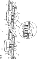
- Fig. 2A and 2B show a first arrangement of the inventive transport assembly 1, using the short load-positioning beam 131, frame 10 and adapter 14 of Fig. 1 .
- a relatively small nacelle is to be transported, i.e. the weight and dimensions of the nacelle allow it to be borne on a single load platform of a transport vehicle.
- two short load-positioning beams 131 are shown in place on the frame 10. Each load-positioning beam 131 spans the frame 10 and is held in place by holding elements 16.
- the holding elements 16 are steel plates shaped in the manner of a claw, with a cut-out 160 that matches the shape of the load-positioning beam 131, so that the load-positioning beam 131 will rest on the load platform and the upper surface of the lateral beams.
- Inner holding plates 16' have a simpler shape, as shown in Fig. 1 , and serve to provide additional stability to the overall arrangement.
- Fig. 1 also indicates through-holes 164 in the holding plates 160 and matching through-holes 134 in fins 133 of the load-positioning beams 131.
- the load-positioning beam 131 is secured to the frame 10 by inserting fasteners F through the aligned through-holes 134, 164 of the holding plates 16 and fins 133.
- the frame 10 and load-positioning beams 131 are now ready to receive the part adapter 14, which can be lowered into place as shown.
- a suitable hoisting or lifting apparatus can be used.
- the diagram shows a row of downward-pointing bars 143 mounted to the part adapter 14.
- Each bar 143 has a number of through-holes 144, so that the part adapter 14 can be secured to a load-positioning beam 131 by inserting fasteners F through the aligned through-holes 134, 144 of the bars 143 and load-positioning beam fins 133, as shown on the right-hand side of the diagram.
- Fig. 3 shows the inventive transport assembly 1 of Fig. 2A and Fig. 2B in use during the transport of a nacelle unit 2.
- the frame 10 has been placed in a predetermined position on the load platform 3 of a transport vehicle (not shown).
- the frame position can have been determined by consideration of the combined weight of the nacelle unit 2 and all the parts already installed in or on the nacelle unit 2, as indicated in the diagram.
- the position of the frame 10 is determined in advance to ensure that the centre of gravity of the nacelle unit 2 will be centrally positioned over the load platform 3.
- the tower head interface 20 of the nacelle unit 2 engages with the part adapter 14.
- the entire assembly can now be safely transported over any distance, and the balanced load distribution ensures that stress damage to the nacelle unit 2 and the transport equipment 1, 3 is avoided.
- Fig. 4 shows a second arrangement of the inventive transport assembly 1, using the long load-positioning beam 132, frame unit 10 and adapter 14 of Fig. 1 .
- a relatively large nacelle unit is to be transported, i.e. the weight and dimensions of the nacelle require the use of two load platforms.
- two long load-positioning beams 132 are shown in place, spanning two frames units 10. Each load-positioning beam 132 spans the two frames units 10 and is held in place by holding plates 16 and fasteners F as described above.
- the frames units 10 and load-positioning beams 132 are now ready to receive the part adapter 14 of a large nacelle unit, which can be lowered into place as shown.
- the part adapter 14 is secured to the load-positioning beams 132 by inserting fasteners F through aligned through-holes 134, 144 of the bars 143 and load-positioning beam fins 133 as shown in the enlarged detail view on the right-hand side of the diagram.
- Fig. 5 shows the inventive transport assembly 1 of Fig. 4 in use during the transport of a large nacelle unit 2.
- the nacelle unit 2 also comprises an entire nacelle with hub and spinner in place at the front of the nacelle, and a cooling arrangement and landing platform in place on top of the nacelle.
- the combined weight of such a nacelle unit 2 can lie in the region of 300 - 800 metric tonnes or even more.
- the frame units 10 have been placed in predetermined positions on adjacent load platforms 3 of a transport vehicle (not shown).
- the load platforms 3 in this case will be jointly pulled by a single transport vehicle.
- the load platforms 3 are effectively held in position by the arrangement of frame units 10 and load-positioning beams 132 of the inventive transport assembly 1.
- the frame positions can have been determined by consideration of the combined weight of the nacelle unit 2, to ensure that the centre of gravity of the nacelle unit 2 will be centrally positioned over the load-carrying area defined by the adjacent load platforms 3 and the load-positioning beams 132.
- the tower head interface of the nacelle unit 2 is secured to the part adapter 14. In this case also, the entire assembly can now be safely transported over any distance, and the balanced load distribution ensures that stress damage to the nacelle unit 2 and the transport equipment 1, 3 is avoided.
- Fig. 6 shows the inventive transport assembly 1 of Fig. 2A and 2B in use during the transport of load 2, in this case a tower head unit.
- the diagram shows the tower head unit in place over a part adapter 14.
- the tower head unit can safely be transported from one location to another during the manufacture of a nacelle unit, for example.
Landscapes
- Engineering & Computer Science (AREA)
- Mechanical Engineering (AREA)
- Life Sciences & Earth Sciences (AREA)
- Sustainable Development (AREA)
- Sustainable Energy (AREA)
- Chemical & Material Sciences (AREA)
- Combustion & Propulsion (AREA)
- General Engineering & Computer Science (AREA)
- Health & Medical Sciences (AREA)
- Public Health (AREA)
- Transportation (AREA)
- Wind Motors (AREA)
Claims (13)
- Assemblage de transport (1) pour arrimer une grande charge lourde (2) à une plateforme de charge (3) pendant une manœuvre de transport, lequel assemblage de transport (1) comprend- une unité de châssis (10) réalisée pour reposer sur une plateforme de charge (3) d'un véhicule de transport ;- un certain nombre de premières poutres de positionnement de charge (131), dans lequel une première poutre de positionnement de charge (131) est réalisée pour enjamber une unique unité de châssis (10) ; et/ou- un certain nombre de secondes poutres de positionnement de charge (132), dans lequel une seconde poutre de positionnement de charge (132) est réalisée pour enjamber une paire d'unités de châssis adjacentes (10) ; et- un adaptateur de pièce (14) réalisé pour venir en prise avec une poutre de positionnement de charge (131, 132) et pour venir en prise avec la charge (2),
caractérisé en ce que l'unité de châssis (10) comprend une pluralité de poutres transversales (11) agencées pour s'étendre d'un coté à l'autre de la largeur de la plateforme de charge (3) et maintenues en place par une paire de poutres latérales (12) agencées pour s'étendre dans la longueur le long des côtés de la plateforme de charge (3) ; et dans lequel une poutre transversale (11) est agencée pour reposer sur une surface supérieure de la plateforme de charge (3). - Assemblage de transport selon la revendication précédente, caractérisé en ce que la première poutre de positionnement de charge (131) est réalisée pour venir en prise avec un adaptateur de pièce (14) positionné de manière centrale au-dessus d'une unique unité de châssis (10), et dans lequel la seconde poutre de positionnement de charge (132) est réalisée pour venir en prise avec un adaptateur de pièce (14) positionné de manière centrale au-dessus d'une paire d'unités de châssis adjacentes (10).
- Assemblage de transport selon l'une quelconque des revendications précédentes, comprenant un agencement de barres (143) montées sur l'adaptateur de pièce (14) et un agencement complémentaire d'ailettes (133) montées sur une poutre de positionnement de charge (131, 132),
caractérisé en ce que lesdites barres (143) et ailettes (133) comprennent des trous traversants correspondants (134, 144) pour recevoir des attaches (F) pour former une liaison entre l'adaptateur de pièce (14) et une poutre de positionnement de charge (131, 132). - Assemblage de transport selon l'une quelconque des revendications précédentes, comprenant un certain nombre d'éléments de maintien (16) agencés pour maintenir une poutre de positionnement de charge (131, 132) en place sur l'unité de châssis (10).
- Assemblage de transport selon la revendication 4, caractérisé en ce qu'un élément de maintien (16) est agencé pour s'étendre vers le haut à partir d'une poutre latérale (12) de l'unité de châssis (10) pour venir en prise depuis le dessous avec une poutre de positionnement de charge (131, 132) .
- Assemblage de transport selon la revendication 4 ou la revendication 5, caractérisé en ce qu'un élément de maintien est agencé pour s'étendre vers le bas à partir d'une poutre de positionnement de charge (131, 132) pour venir en prise depuis le dessus avec une poutre latérale (12) de l'unité de châssis (10) .
- Assemblage de transport selon l'une quelconque des revendications 4 à 6, caractérisé en ce qu'un élément de maintien (16) est construit sous la forme d'une plaque (16) comprenant une découpe rectangulaire (160) pour s'ajuster autour d'une poutre de positionnement de charge (131, 132).
- Assemblage de transport selon la revendication 7, comprenant un agencement correspondant de trous traversants (164) dans une plaque de maintien (164) et dans un agencement complémentaire d'ailettes (134) montées sur une poutre de positionnement de charge (131, 132), pour recevoir des attaches (F) pour arrimer la poutre de positionnement de charge (131, 132) à l'unité de châssis (10).
- Assemblage de transport selon l'une quelconque des revendications précédentes, réalisé pour transporter une unité de nacelle d'éolienne (2) ayant un poids d'au moins 200 tonnes métriques.
- Assemblage de transport selon l'une quelconque des revendications précédentes, dans lequel l'adaptateur de pièce (14) est réalisé pour se relier à une interface de tête de tour d'éolienne (2) ayant un diamètre d'au moins 4 m.
- Procédé d'arrimage d'une grande charge lourde (2) sur une plateforme de charge (3) pendant une manœuvre de transport, à l'aide d'un assemblage de transport (1) selon l'une quelconque des revendications 1 à 10, lequel procédé comprend les étapes de- l'agencement d'une unique unité de châssis (10) d'un assemblage de transport (1) selon l'une quelconque des revendications 1 à 10 au-dessus d'une plateforme de charge (3) et l'agencement d'au moins une première poutre de positionnement de charge (131) d'un coté à l'autre de l'unique unité de châssis (10), ou- l'agencement de deux unités de châssis (10) d'un assemblage de transport (1) selon l'une quelconque des revendications 1 à 10 au-dessus d'une paire de plateformes de charge adjacentes (3), et l'agencement d'au moins une seconde poutre de positionnement de charge (132) d'un coté à l'autre des unités de châssis (10) ; et par la suite- la mise en prise d'un adaptateur de pièce (14) de l'assemblage de transport (1) avec une poutre de positionnement de charge (131, 132) ; et- la mise en prise de la charge (2) avec l'adaptateur de pièce (14) .
- Procédé selon la revendication 11, comprenant une étape préliminaire de détermination d'une position optimale pour l'unité de châssis (10) sur la plateforme de charge (3) sur la base du poids de la charge (2) et/ou de la forme de la charge (2) .
- Procédé selon la revendication 11 ou la revendication 12, comprenant une étape préliminaire de détermination d'une position optimale des poutres transversales (11) et/ou des poutres de positionnement de charge (131, 132) par rapport aux poutres latérales (12) de l'unité de châssis (1) sur la base du poids de la charge (2) et/ou de la forme de la charge (2).
Applications Claiming Priority (2)
| Application Number | Priority Date | Filing Date | Title |
|---|---|---|---|
| DE102016222212 | 2016-11-11 | ||
| PCT/EP2017/076684 WO2018086837A1 (fr) | 2016-11-11 | 2017-10-19 | Assemblage de transport |
Publications (2)
| Publication Number | Publication Date |
|---|---|
| EP3510280A1 EP3510280A1 (fr) | 2019-07-17 |
| EP3510280B1 true EP3510280B1 (fr) | 2020-09-16 |
Family
ID=60201543
Family Applications (1)
| Application Number | Title | Priority Date | Filing Date |
|---|---|---|---|
| EP17792010.5A Active EP3510280B1 (fr) | 2016-11-11 | 2017-10-19 | Assemblage de transport |
Country Status (5)
| Country | Link |
|---|---|
| US (2) | US11506179B2 (fr) |
| EP (1) | EP3510280B1 (fr) |
| CN (1) | CN109996958B (fr) |
| DK (1) | DK3510280T3 (fr) |
| WO (1) | WO2018086837A1 (fr) |
Families Citing this family (10)
| Publication number | Priority date | Publication date | Assignee | Title |
|---|---|---|---|---|
| US11506179B2 (en) * | 2016-11-11 | 2022-11-22 | Siemens Gamesa Renewable Energy A/S | Transport assembly |
| EP3617499B1 (fr) * | 2018-08-29 | 2022-11-23 | Siemens Gamesa Renewable Energy A/S | Transport d'un composant d'éolienne |
| CN111017765B (zh) * | 2019-11-28 | 2021-06-25 | 海洋石油工程(青岛)有限公司 | 一种用扁担梁牵引大型结构物的新工艺 |
| EP3863232B1 (fr) * | 2020-02-06 | 2023-06-21 | Nxp B.V. | Émetteur-récepteur monolithique haute tension connecté à deux domaines de tension d'alimentation différents |
| EP3885192A1 (fr) * | 2020-03-16 | 2021-09-29 | Blue Water Shipping A/S | Procédé de chargement de composants d'éolienne sur un vaisseau maritime |
| EP3904675B1 (fr) | 2020-04-28 | 2025-07-09 | Siemens Gamesa Renewable Energy A/S | Procédés et système pour le transport d'un composant d'une éolienne |
| CN112706687B (zh) * | 2020-12-30 | 2022-06-03 | 三一重能股份有限公司 | 运输工装及运输系统 |
| BE1029054B1 (nl) * | 2021-01-26 | 2022-08-29 | Sarens | Draagstructuur voor het laden en lossen en transporteren van een last gebruik makend van SPMT trailers en transportsysteem daarmee uitgerust |
| PL4230864T3 (pl) * | 2022-02-22 | 2025-06-09 | Eew Special Pipe Constructions Gmbh | System mocowania rur do pojazdów ciężarowych i sposób podpierania rury na pojeździe ciężarowym |
| EP4477879A1 (fr) | 2023-06-15 | 2024-12-18 | Siemens Gamesa Renewable Energy A/S | Système de transport pour composants d'éolienne |
Family Cites Families (19)
| Publication number | Priority date | Publication date | Assignee | Title |
|---|---|---|---|---|
| US1780277A (en) * | 1929-01-05 | 1930-11-04 | Evans Auto Loading Co Inc | Shipping device |
| US5344266A (en) * | 1993-04-16 | 1994-09-06 | Kolb Peter W | Fully adjustable storage device for loading and transporting vehicles in containers |
| US5954465A (en) * | 1997-03-13 | 1999-09-21 | Excell Fabrication Service Inc. | Flatbed cylindrical load securing device |
| US6334746B1 (en) * | 2000-03-31 | 2002-01-01 | General Electric Company | Transport system for a power generation unit |
| ATE415311T1 (de) | 2003-05-15 | 2008-12-15 | Vestas Wind Sys As | Transportsystem für ein windturbinenbauteil und verfahren zum transport eines windturbinenbauteils |
| ES2341525B1 (es) * | 2008-12-19 | 2011-05-20 | GAMESA INNOVATION & TECHNOLOGY, S.L. | Util para el transporte de torres. |
| DE202010000868U1 (de) | 2009-07-20 | 2010-12-02 | Wader-Wittis Gmbh | Vorrichtung zum Transport und zur Montage von Windkraftanlagen |
| DK2333312T3 (en) | 2009-12-08 | 2016-08-15 | Siemens Ag | Wind turbine transport device |
| DK2395240T3 (en) * | 2010-06-11 | 2015-11-16 | Siemens Ag | Windkraftanlagen Nacelle, transport to a wind turbines nacelle and method for transporting a wind turbines nacelle |
| PL3026258T3 (pl) * | 2010-08-12 | 2019-12-31 | Lm Wp Patent Holding A/S | Układ do transportowania i składowania łopat turbin wiatrowych |
| EP2652320B1 (fr) | 2010-12-15 | 2016-08-24 | Vestas Wind Systems A/S | Outil et procédé pour le déplacement d'un composant de transmission d'éolienne |
| DE102011003164A1 (de) | 2011-01-26 | 2012-07-26 | Aloys Wobben | Verfahren und Vorrichtung zum Errichten eines Turms einer Windenergieanlage |
| DK2481631T3 (da) | 2011-02-01 | 2019-05-27 | Siemens Gamesa Renewable Energy As | Transportstruktur og fremgangsmåder til at transportere og/eller løfte en stor generator |
| US8967930B2 (en) * | 2011-04-28 | 2015-03-03 | VIGGO JESPERSEN HOLDING ApS | Transport system for large items |
| DE102012002755A1 (de) | 2012-02-11 | 2013-08-14 | Ge Wind Energy Gmbh | Verfahren zum Handhaben von Turmsegmenten für einen Turm und Vorrichtung zur Handhabung von Turmsegmenten |
| NL2010545C2 (en) | 2013-03-28 | 2014-09-30 | Ihc Holland Ie Bv | Skidding system for an offshore installation or vessel. |
| CN205207043U (zh) | 2015-11-25 | 2016-05-04 | 河北省电力勘测设计研究院 | 波浪发电装置 |
| CN205207053U (zh) | 2015-12-11 | 2016-05-04 | 沧州惠邦机电产品制造有限责任公司 | 一种大型风力发电机舱海运支架 |
| US11506179B2 (en) * | 2016-11-11 | 2022-11-22 | Siemens Gamesa Renewable Energy A/S | Transport assembly |
-
2017
- 2017-10-19 US US16/347,878 patent/US11506179B2/en active Active
- 2017-10-19 CN CN201780069808.7A patent/CN109996958B/zh active Active
- 2017-10-19 WO PCT/EP2017/076684 patent/WO2018086837A1/fr not_active Ceased
- 2017-10-19 DK DK17792010.5T patent/DK3510280T3/da active
- 2017-10-19 EP EP17792010.5A patent/EP3510280B1/fr active Active
-
2021
- 2021-12-22 US US17/558,635 patent/US12018648B2/en active Active
Non-Patent Citations (1)
| Title |
|---|
| None * |
Also Published As
| Publication number | Publication date |
|---|---|
| US11506179B2 (en) | 2022-11-22 |
| US20220112882A1 (en) | 2022-04-14 |
| EP3510280A1 (fr) | 2019-07-17 |
| DK3510280T3 (da) | 2020-11-09 |
| US12018648B2 (en) | 2024-06-25 |
| CN109996958B (zh) | 2021-08-24 |
| WO2018086837A1 (fr) | 2018-05-17 |
| US20190285057A1 (en) | 2019-09-19 |
| CN109996958A (zh) | 2019-07-09 |
Similar Documents
| Publication | Publication Date | Title |
|---|---|---|
| EP3510280B1 (fr) | Assemblage de transport | |
| US8342491B2 (en) | Transport system for transportation of a spar | |
| DK2456973T3 (en) | PROCEDURE AND DEVICE FOR TRANSPORTING AND FITTING WINDOWS | |
| ES2950641T3 (es) | Conjunto de almacenamiento de estructura de acero de base intercambiable | |
| CN103026060B (zh) | 用于操纵风力涡轮机塔架段的系统及方法 | |
| CN104554623B (zh) | 船艉部总段运输工装 | |
| JP2011122591A (ja) | 風車ハブ輸送装置 | |
| US9969416B2 (en) | Scaffold storage and transportation dolly set | |
| US12258938B2 (en) | Transporting a wind turbine component | |
| US8845248B2 (en) | Transport structure and methods for transporting and/or lifting a large scale generator | |
| EP2361217B1 (fr) | Système et procédé pour manipuler une nacelle d'une éolienne | |
| CN203806420U (zh) | 用于风力发电机组的构件的运输装置和运输系统 | |
| CN102234084A (zh) | 定位大型负载于运输、存储位置的方法、拖车和/或卡车 | |
| US11448197B2 (en) | Modular tool | |
| JP4208248B2 (ja) | 送電線鉄塔の嵩上げ方法 | |
| US20210032052A1 (en) | Structure for transport and organization of large power cables on a wellsite | |
| CN102674165B (zh) | 从燃气涡轮的辅助隔室移除扭矩变换器和启动马达的方法 | |
| KR20140006129U (ko) | 족장판 운반장치 | |
| CN210885075U (zh) | 一种设备二次运输及就位的吊装架 | |
| CN219341464U (zh) | 一种反力墙及反力台座加载孔模块运输保护装置 | |
| KR102049892B1 (ko) | 팹의 기계실 모듈 시공방법 | |
| CN111989484A (zh) | 液压蓄积器更换工具 | |
| US12545173B2 (en) | Pipe securing system for heavy-duty vehicles and method for supporting a pipe on a heavy-duty vehicle | |
| CN212711055U (zh) | 一种用于成袋面粉的输送装置 | |
| CN217228273U (zh) | 一种用于收卷客机衣膜的横梁放置架 |
Legal Events
| Date | Code | Title | Description |
|---|---|---|---|
| STAA | Information on the status of an ep patent application or granted ep patent |
Free format text: STATUS: UNKNOWN |
|
| STAA | Information on the status of an ep patent application or granted ep patent |
Free format text: STATUS: THE INTERNATIONAL PUBLICATION HAS BEEN MADE |
|
| PUAI | Public reference made under article 153(3) epc to a published international application that has entered the european phase |
Free format text: ORIGINAL CODE: 0009012 |
|
| STAA | Information on the status of an ep patent application or granted ep patent |
Free format text: STATUS: REQUEST FOR EXAMINATION WAS MADE |
|
| 17P | Request for examination filed |
Effective date: 20190410 |
|
| AK | Designated contracting states |
Kind code of ref document: A1 Designated state(s): AL AT BE BG CH CY CZ DE DK EE ES FI FR GB GR HR HU IE IS IT LI LT LU LV MC MK MT NL NO PL PT RO RS SE SI SK SM TR |
|
| GRAP | Despatch of communication of intention to grant a patent |
Free format text: ORIGINAL CODE: EPIDOSNIGR1 |
|
| STAA | Information on the status of an ep patent application or granted ep patent |
Free format text: STATUS: GRANT OF PATENT IS INTENDED |
|
| INTG | Intention to grant announced |
Effective date: 20200429 |
|
| GRAS | Grant fee paid |
Free format text: ORIGINAL CODE: EPIDOSNIGR3 |
|
| GRAA | (expected) grant |
Free format text: ORIGINAL CODE: 0009210 |
|
| STAA | Information on the status of an ep patent application or granted ep patent |
Free format text: STATUS: THE PATENT HAS BEEN GRANTED |
|
| AK | Designated contracting states |
Kind code of ref document: B1 Designated state(s): AL AT BE BG CH CY CZ DE DK EE ES FI FR GB GR HR HU IE IS IT LI LT LU LV MC MK MT NL NO PL PT RO RS SE SI SK SM TR |
|
| REG | Reference to a national code |
Ref country code: GB Ref legal event code: FG4D |
|
| REG | Reference to a national code |
Ref country code: CH Ref legal event code: EP |
|
| REG | Reference to a national code |
Ref country code: DE Ref legal event code: R096 Ref document number: 602017023848 Country of ref document: DE |
|
| REG | Reference to a national code |
Ref country code: IE Ref legal event code: FG4D |
|
| REG | Reference to a national code |
Ref country code: AT Ref legal event code: REF Ref document number: 1314376 Country of ref document: AT Kind code of ref document: T Effective date: 20201015 |
|
| REG | Reference to a national code |
Ref country code: DK Ref legal event code: T3 Effective date: 20201104 |
|
| REG | Reference to a national code |
Ref country code: NL Ref legal event code: FP |
|
| PG25 | Lapsed in a contracting state [announced via postgrant information from national office to epo] |
Ref country code: HR Free format text: LAPSE BECAUSE OF FAILURE TO SUBMIT A TRANSLATION OF THE DESCRIPTION OR TO PAY THE FEE WITHIN THE PRESCRIBED TIME-LIMIT Effective date: 20200916 Ref country code: SE Free format text: LAPSE BECAUSE OF FAILURE TO SUBMIT A TRANSLATION OF THE DESCRIPTION OR TO PAY THE FEE WITHIN THE PRESCRIBED TIME-LIMIT Effective date: 20200916 Ref country code: FI Free format text: LAPSE BECAUSE OF FAILURE TO SUBMIT A TRANSLATION OF THE DESCRIPTION OR TO PAY THE FEE WITHIN THE PRESCRIBED TIME-LIMIT Effective date: 20200916 Ref country code: NO Free format text: LAPSE BECAUSE OF FAILURE TO SUBMIT A TRANSLATION OF THE DESCRIPTION OR TO PAY THE FEE WITHIN THE PRESCRIBED TIME-LIMIT Effective date: 20201216 Ref country code: GR Free format text: LAPSE BECAUSE OF FAILURE TO SUBMIT A TRANSLATION OF THE DESCRIPTION OR TO PAY THE FEE WITHIN THE PRESCRIBED TIME-LIMIT Effective date: 20201217 Ref country code: BG Free format text: LAPSE BECAUSE OF FAILURE TO SUBMIT A TRANSLATION OF THE DESCRIPTION OR TO PAY THE FEE WITHIN THE PRESCRIBED TIME-LIMIT Effective date: 20201216 |
|
| REG | Reference to a national code |
Ref country code: AT Ref legal event code: MK05 Ref document number: 1314376 Country of ref document: AT Kind code of ref document: T Effective date: 20200916 |
|
| PG25 | Lapsed in a contracting state [announced via postgrant information from national office to epo] |
Ref country code: RS Free format text: LAPSE BECAUSE OF FAILURE TO SUBMIT A TRANSLATION OF THE DESCRIPTION OR TO PAY THE FEE WITHIN THE PRESCRIBED TIME-LIMIT Effective date: 20200916 Ref country code: LV Free format text: LAPSE BECAUSE OF FAILURE TO SUBMIT A TRANSLATION OF THE DESCRIPTION OR TO PAY THE FEE WITHIN THE PRESCRIBED TIME-LIMIT Effective date: 20200916 |
|
| REG | Reference to a national code |
Ref country code: LT Ref legal event code: MG4D |
|
| PG25 | Lapsed in a contracting state [announced via postgrant information from national office to epo] |
Ref country code: CZ Free format text: LAPSE BECAUSE OF FAILURE TO SUBMIT A TRANSLATION OF THE DESCRIPTION OR TO PAY THE FEE WITHIN THE PRESCRIBED TIME-LIMIT Effective date: 20200916 Ref country code: PT Free format text: LAPSE BECAUSE OF FAILURE TO SUBMIT A TRANSLATION OF THE DESCRIPTION OR TO PAY THE FEE WITHIN THE PRESCRIBED TIME-LIMIT Effective date: 20210118 Ref country code: RO Free format text: LAPSE BECAUSE OF FAILURE TO SUBMIT A TRANSLATION OF THE DESCRIPTION OR TO PAY THE FEE WITHIN THE PRESCRIBED TIME-LIMIT Effective date: 20200916 Ref country code: EE Free format text: LAPSE BECAUSE OF FAILURE TO SUBMIT A TRANSLATION OF THE DESCRIPTION OR TO PAY THE FEE WITHIN THE PRESCRIBED TIME-LIMIT Effective date: 20200916 Ref country code: SM Free format text: LAPSE BECAUSE OF FAILURE TO SUBMIT A TRANSLATION OF THE DESCRIPTION OR TO PAY THE FEE WITHIN THE PRESCRIBED TIME-LIMIT Effective date: 20200916 Ref country code: LT Free format text: LAPSE BECAUSE OF FAILURE TO SUBMIT A TRANSLATION OF THE DESCRIPTION OR TO PAY THE FEE WITHIN THE PRESCRIBED TIME-LIMIT Effective date: 20200916 |
|
| PG25 | Lapsed in a contracting state [announced via postgrant information from national office to epo] |
Ref country code: AT Free format text: LAPSE BECAUSE OF FAILURE TO SUBMIT A TRANSLATION OF THE DESCRIPTION OR TO PAY THE FEE WITHIN THE PRESCRIBED TIME-LIMIT Effective date: 20200916 Ref country code: AL Free format text: LAPSE BECAUSE OF FAILURE TO SUBMIT A TRANSLATION OF THE DESCRIPTION OR TO PAY THE FEE WITHIN THE PRESCRIBED TIME-LIMIT Effective date: 20200916 Ref country code: ES Free format text: LAPSE BECAUSE OF FAILURE TO SUBMIT A TRANSLATION OF THE DESCRIPTION OR TO PAY THE FEE WITHIN THE PRESCRIBED TIME-LIMIT Effective date: 20200916 Ref country code: IS Free format text: LAPSE BECAUSE OF FAILURE TO SUBMIT A TRANSLATION OF THE DESCRIPTION OR TO PAY THE FEE WITHIN THE PRESCRIBED TIME-LIMIT Effective date: 20210116 Ref country code: PL Free format text: LAPSE BECAUSE OF FAILURE TO SUBMIT A TRANSLATION OF THE DESCRIPTION OR TO PAY THE FEE WITHIN THE PRESCRIBED TIME-LIMIT Effective date: 20200916 |
|
| REG | Reference to a national code |
Ref country code: CH Ref legal event code: PL |
|
| REG | Reference to a national code |
Ref country code: DE Ref legal event code: R097 Ref document number: 602017023848 Country of ref document: DE |
|
| PG25 | Lapsed in a contracting state [announced via postgrant information from national office to epo] |
Ref country code: LU Free format text: LAPSE BECAUSE OF NON-PAYMENT OF DUE FEES Effective date: 20201019 Ref country code: SK Free format text: LAPSE BECAUSE OF FAILURE TO SUBMIT A TRANSLATION OF THE DESCRIPTION OR TO PAY THE FEE WITHIN THE PRESCRIBED TIME-LIMIT Effective date: 20200916 Ref country code: MC Free format text: LAPSE BECAUSE OF FAILURE TO SUBMIT A TRANSLATION OF THE DESCRIPTION OR TO PAY THE FEE WITHIN THE PRESCRIBED TIME-LIMIT Effective date: 20200916 |
|
| REG | Reference to a national code |
Ref country code: BE Ref legal event code: MM Effective date: 20201031 |
|
| PLBE | No opposition filed within time limit |
Free format text: ORIGINAL CODE: 0009261 |
|
| STAA | Information on the status of an ep patent application or granted ep patent |
Free format text: STATUS: NO OPPOSITION FILED WITHIN TIME LIMIT |
|
| 26N | No opposition filed |
Effective date: 20210617 |
|
| PG25 | Lapsed in a contracting state [announced via postgrant information from national office to epo] |
Ref country code: SI Free format text: LAPSE BECAUSE OF FAILURE TO SUBMIT A TRANSLATION OF THE DESCRIPTION OR TO PAY THE FEE WITHIN THE PRESCRIBED TIME-LIMIT Effective date: 20200916 Ref country code: LI Free format text: LAPSE BECAUSE OF NON-PAYMENT OF DUE FEES Effective date: 20201031 Ref country code: CH Free format text: LAPSE BECAUSE OF NON-PAYMENT OF DUE FEES Effective date: 20201031 Ref country code: BE Free format text: LAPSE BECAUSE OF NON-PAYMENT OF DUE FEES Effective date: 20201031 |
|
| PG25 | Lapsed in a contracting state [announced via postgrant information from national office to epo] |
Ref country code: IT Free format text: LAPSE BECAUSE OF FAILURE TO SUBMIT A TRANSLATION OF THE DESCRIPTION OR TO PAY THE FEE WITHIN THE PRESCRIBED TIME-LIMIT Effective date: 20200916 Ref country code: IE Free format text: LAPSE BECAUSE OF NON-PAYMENT OF DUE FEES Effective date: 20201019 |
|
| PG25 | Lapsed in a contracting state [announced via postgrant information from national office to epo] |
Ref country code: TR Free format text: LAPSE BECAUSE OF FAILURE TO SUBMIT A TRANSLATION OF THE DESCRIPTION OR TO PAY THE FEE WITHIN THE PRESCRIBED TIME-LIMIT Effective date: 20200916 Ref country code: MT Free format text: LAPSE BECAUSE OF FAILURE TO SUBMIT A TRANSLATION OF THE DESCRIPTION OR TO PAY THE FEE WITHIN THE PRESCRIBED TIME-LIMIT Effective date: 20200916 Ref country code: CY Free format text: LAPSE BECAUSE OF FAILURE TO SUBMIT A TRANSLATION OF THE DESCRIPTION OR TO PAY THE FEE WITHIN THE PRESCRIBED TIME-LIMIT Effective date: 20200916 |
|
| PG25 | Lapsed in a contracting state [announced via postgrant information from national office to epo] |
Ref country code: MK Free format text: LAPSE BECAUSE OF FAILURE TO SUBMIT A TRANSLATION OF THE DESCRIPTION OR TO PAY THE FEE WITHIN THE PRESCRIBED TIME-LIMIT Effective date: 20200916 |
|
| REG | Reference to a national code |
Ref country code: DE Ref legal event code: R082 Ref document number: 602017023848 Country of ref document: DE Representative=s name: SAUTHOFF, KARSTEN, DIPL.-ING. UNIV., DE |
|
| PGFP | Annual fee paid to national office [announced via postgrant information from national office to epo] |
Ref country code: NL Payment date: 20241023 Year of fee payment: 8 |
|
| PGFP | Annual fee paid to national office [announced via postgrant information from national office to epo] |
Ref country code: DK Payment date: 20250901 Year of fee payment: 9 |
|
| PGFP | Annual fee paid to national office [announced via postgrant information from national office to epo] |
Ref country code: GB Payment date: 20250901 Year of fee payment: 9 |
|
| PGFP | Annual fee paid to national office [announced via postgrant information from national office to epo] |
Ref country code: DE Payment date: 20250731 Year of fee payment: 9 |
|
| PGFP | Annual fee paid to national office [announced via postgrant information from national office to epo] |
Ref country code: FR Payment date: 20251027 Year of fee payment: 9 |