EP3510465B1 - Bediengerät - Google Patents
Bediengerät Download PDFInfo
- Publication number
- EP3510465B1 EP3510465B1 EP17752095.4A EP17752095A EP3510465B1 EP 3510465 B1 EP3510465 B1 EP 3510465B1 EP 17752095 A EP17752095 A EP 17752095A EP 3510465 B1 EP3510465 B1 EP 3510465B1
- Authority
- EP
- European Patent Office
- Prior art keywords
- latch
- control apparatus
- operator control
- accordance
- head
- Prior art date
- Legal status (The legal status is an assumption and is not a legal conclusion. Google has not performed a legal analysis and makes no representation as to the accuracy of the status listed.)
- Not-in-force
Links
- 230000008878 coupling Effects 0.000 claims description 13
- 238000010168 coupling process Methods 0.000 claims description 13
- 238000005859 coupling reaction Methods 0.000 claims description 13
- 230000007246 mechanism Effects 0.000 claims description 9
- 230000005540 biological transmission Effects 0.000 description 10
- 230000008859 change Effects 0.000 description 10
- 230000001419 dependent effect Effects 0.000 description 3
- 230000003993 interaction Effects 0.000 description 3
- 238000007789 sealing Methods 0.000 description 3
- 238000007598 dipping method Methods 0.000 description 2
- 230000002349 favourable effect Effects 0.000 description 2
- 239000000463 material Substances 0.000 description 2
- 230000008901 benefit Effects 0.000 description 1
- 230000000295 complement effect Effects 0.000 description 1
- 238000010276 construction Methods 0.000 description 1
- 230000006735 deficit Effects 0.000 description 1
- 238000001514 detection method Methods 0.000 description 1
- 230000005489 elastic deformation Effects 0.000 description 1
- 238000005516 engineering process Methods 0.000 description 1
- 238000007654 immersion Methods 0.000 description 1
- 230000001771 impaired effect Effects 0.000 description 1
- ORQBXQOJMQIAOY-UHFFFAOYSA-N nobelium Chemical compound [No] ORQBXQOJMQIAOY-UHFFFAOYSA-N 0.000 description 1
- 238000005192 partition Methods 0.000 description 1
Images


Classifications
-
- B—PERFORMING OPERATIONS; TRANSPORTING
- B66—HOISTING; LIFTING; HAULING
- B66C—CRANES; LOAD-ENGAGING ELEMENTS OR DEVICES FOR CRANES, CAPSTANS, WINCHES, OR TACKLES
- B66C13/00—Other constructional features or details
- B66C13/18—Control systems or devices
- B66C13/40—Applications of devices for transmitting control pulses; Applications of remote control devices
-
- G—PHYSICS
- G05—CONTROLLING; REGULATING
- G05G—CONTROL DEVICES OR SYSTEMS INSOFAR AS CHARACTERISED BY MECHANICAL FEATURES ONLY
- G05G1/00—Controlling members, e.g. knobs or handles; Assemblies or arrangements thereof; Indicating position of controlling members
- G05G1/02—Controlling members for hand actuation by linear movement, e.g. push buttons
-
- G—PHYSICS
- G05—CONTROLLING; REGULATING
- G05G—CONTROL DEVICES OR SYSTEMS INSOFAR AS CHARACTERISED BY MECHANICAL FEATURES ONLY
- G05G1/00—Controlling members, e.g. knobs or handles; Assemblies or arrangements thereof; Indicating position of controlling members
- G05G1/08—Controlling members for hand actuation by rotary movement, e.g. hand wheels
- G05G1/10—Details, e.g. of discs, knobs, wheels or handles
- G05G1/12—Means for securing the members on rotatable spindles or the like
-
- G—PHYSICS
- G05—CONTROLLING; REGULATING
- G05G—CONTROL DEVICES OR SYSTEMS INSOFAR AS CHARACTERISED BY MECHANICAL FEATURES ONLY
- G05G1/00—Controlling members, e.g. knobs or handles; Assemblies or arrangements thereof; Indicating position of controlling members
- G05G1/54—Controlling members specially adapted for actuation by auxiliary operating members or extensions; Operating members or extensions therefor (pedal extensions)
-
- G—PHYSICS
- G05—CONTROLLING; REGULATING
- G05G—CONTROL DEVICES OR SYSTEMS INSOFAR AS CHARACTERISED BY MECHANICAL FEATURES ONLY
- G05G25/00—Other details or appurtenances of control mechanisms, e.g. supporting intermediate members elastically
- G05G25/04—Sealing against entry of dust, weather or the like
Definitions
- the invention relates to an operating device, in particular a remote control, with a splash-proof housing and with at least one operating device, which has an input device with a key head that can be moved manually along a longitudinal axis, a rotary member that can be rotated about an axis of rotation and a coupling mechanism, the coupling mechanism being used for a linear movement of the key top can be transmitted into a rotary movement of the rotary member, and wherein a signal transmitter is held non-rotatably on the rotary member and cooperates with a sensor element arranged in the housing.
- Such operating devices are also referred to as manually operable control devices and can be configured, for example, as remote controls, in particular as radio remote controls.
- the user can enter a control command by actuating a key head, which command can then be transmitted to a technical device to be controlled via a transmission channel.
- the transmission can take place via a remote control line, in particular via a remote control cable, or wirelessly, for example via an infrared or radio link.
- an operating device with a splash-proof housing and an operating device is known.
- the operating device has an input device with a displaceable and rotatable key head which carries several signal transmitters which interact with a sensor arranged in the housing.
- the input device can be inserted into a recess on the outside of the housing.
- Control devices of the type mentioned are used, for example, as remote controls in forestry and construction technology, in particular for controlling cranes and lifting devices.
- the operating devices For entering control commands the operating devices have at least one operating device with a key head that can be moved manually by the user along a longitudinal axis.
- the key top is coupled via a coupling mechanism to a rotary member rotatable about an axis of rotation, a linear movement of the key top being transferable into a rotary movement of the rotary member via the coupling mechanism.
- a signal transmitter is held non-rotatably on the rotary link, which interacts with a sensor element of the control unit.
- the rotary member and with it also the signal transmitter can be set in rotation and the rotary position and / or change in the rotary position of the signal transmitter can be detected by means of the sensor element. This gives the user the option of entering control commands that are dependent on the movement of the key head.
- Such operating devices in particular in the form of remote controls, are often used in a harsh environment.
- the operating devices therefore have a splash-proof housing in which control and transmission electronics are arranged.
- the control command entered by the user can be evaluated by means of the control and transmission electronics, and a corresponding control signal can be transmitted to the device to be controlled, for example a crane, for example via a radio link.
- the object of the present invention is to develop an operating device of the type mentioned at the outset in such a way that the at least one input device can be mounted in a simple manner and replaced in a simple manner.
- this object is achieved according to the invention in that the input device can be inserted into an external recess of the housing of the operating device and can be removed from the recess if necessary.
- the splash-proof housing of the operating device has a number of depressions corresponding to the number of input devices used, so that each input device can be inserted into an associated depression of the housing in an assembly direction.
- the depressions are arranged on the outside of the housing, for example on its upper side. This facilitates the assembly and replacement of the input devices, since it is necessary to insert an input device in an outside recess of the housing is not necessary to open the splash-proof housing. If an input device is to be exchanged, it can be removed from the recess, and the exchange can take place without opening the housing. In particular, the exchange can take place without the risk of a seal of the housing being damaged.
- the input device forms a pre-assemblable structural unit, because this gives the possibility of inserting the input device in the form of a structural unit into a recess in the housing.
- the rotational position and / or change in the rotational position of the signal transmitter can be detected by the associated sensor element, so that the sensor element of the control and transmission electronics of the operating device can provide a sensor signal dependent on the rotational position and / or rotational position change of the signal transmitter.
- the interaction of the signal transmitter and the sensor element can take place in a touch-based manner.
- the sensor element arranged in the housing of the operating device is designed as a rotary potentiometer and that the signal transmitter arranged on the associated rotary element is designed in the form of a driver that engages the rotary potentiometer.
- the signal transmitter interacts with the sensor element in a contactless manner, since this can prevent mechanical impairment of the associated sensor element by the signal transmitter.
- the contactless interaction of signal transmitter and sensor element also has the advantage that the sensor element can detect the rotational position and / or change in rotational position of the signal transmitter even if a wall section of the housing of the operating device is arranged between the signal transmitter and the sensor element.
- the wall section can preferably be made of a plastic material that enables the detection the rotational position and / or the change in rotational position is practically not affected by the sensor element.
- a contactless interaction of the signal transmitter with the sensor element therefore allows the recess in the housing, which receives the input device, to be configured without openings.
- the signal transmitter like the remaining components of the input device, can thus be arranged completely on the outside of the housing and does not have to protrude into the interior of the housing. This facilitates the assembly and replacement of the input device.
- the signal transmitter is designed as a permanent magnet and the sensor element assigned to the signal transmitter is sensitive to magnetic fields.
- the rotary position of the permanent magnet arranged on the rotary member can be changed, and this in turn has the consequence that the direction of the magnetic field generated by the permanent magnet changes.
- the change in direction can be detected by the magnetic field-sensitive sensor element, which can then provide the control and transmission electronics of the operating device with a corresponding sensor signal.
- the permanent magnet is advantageously magnetized transversely to the axis of rotation of the rotary member.
- the at least one operating device preferably has a connecting element which encompasses the input device and which can be placed on the input device and detachably connected, in particular screwed, to the housing.
- the connecting element can engage behind the input device.
- the input device can be inserted into a recess on the outside of the housing and the connecting element can be attached to the input device placed and releasably connected to the housing, so that the input device is fixed in the recess of the housing.
- the connecting element is designed in the manner of a coupling ring which can be screwed to the housing.
- the recess of the housing preferably has a support surface and the input device has a support part, which is supported on the support surface, preferably with the interposition of a sealing element, for example a sealing ring.
- a sealing element for example a sealing ring.
- the support surface can form, for example, a narrowing of the recess of the housing, in particular a step over which the diameter of the recess is reduced.
- the support part preferably forms a holder for the rotary member.
- the support part not only has the function of supporting the input device on a support surface, but the support part also has a holding function for the rotary member.
- the rotary member is held axially immovable and rotatable on the support part.
- the support part has a guide sleeve on which the rotary member is rotatably held.
- the input device has an elastically deformable cover part.
- the cover part can for example be designed in the form of a bellows.
- the cover part is made from an elastically deformable plastic material.
- the elastically deformable cover part engages under the key top which can be manually operated by the user.
- the key top is connected to the cover part in a splash-proof manner.
- the axis of rotation of the rotary member is advantageously aligned collinear to the longitudinal axis of the input device.
- the coupling mechanism has a plunger held on the key top, which is coupled to the rotary member via a driver and a guide slot, the driver dipping into the guide slot and the guide slot being curved axially in relation to the longitudinal axis Direction and extends in the circumferential direction.
- the plunger is connected to the key top and can be moved together with the key top along the longitudinal axis. The linear movement of the plunger is converted into a rotary movement of the rotary member via the driver and the guide slot into which the driver dips.
- the guide slot is curved in the manner of a helix and extends both in the axial direction and in the circumferential direction.
- the driver and the guide slot thus form a control link that converts a linear movement into a rotary movement.
- the driver is designed in the form of a pin and protrudes with at least one end in the radial direction from the plunger, with its protruding end dipping into a guide slot of the rotary member.
- the driver is designed as a driving pin which diametrically reaches through the plunger and engages with its two ends in a guide slot of the rotary member.
- the at least one input device preferably allows infinitely variable command input in that the rotary position of the rotary member changes continuously as a function of the extent of the stroke movement of the key top.
- the at least one input device has at least one latching element with a latching head to which at least one latching recess is assigned, into which the latching head dips when a predetermined stroke position of the key head is reached.
- the immersion of the latching head in a latching recess gives the user tactile feedback by means of which he can recognize that the key head has reached a certain stroke position.
- the latching head is preferably elastically pretensioned in the direction of the latching recess.
- the at least one locking element is assigned a plurality of locking depressions arranged one behind the other in relation to the longitudinal axis are, into which the latching head of the latching element dips one after the other during a lifting movement of the key head. If the key head is moved by the user along the longitudinal axis, the latching head dips into a latching recess when the predetermined stroke position is reached and thus gives the user tactile feedback about the reaching of the respective stroke position. This facilitates the handling of the control device, especially in cases in which the user operates the control device with gloves.
- the at least one locking recess is adapted to the shape of the associated locking head. This allows a not only punctiform but linear or flat contact of the locking head on the locking recess. As a result, the wear on the at least one locking recess and the locking head can be kept low.
- the at least one latching element is assigned a running groove aligned parallel to the longitudinal axis into which the latching head of the latching element is permanently immersed, the at least one latching recess associated with the latching element being arranged in the running groove.
- the running groove extends parallel to the longitudinal axis of the input device, and when the key top is moved, the latching head of the latching element assigned to the running groove slides along the running groove. The locking head is thus permanently immersed in the running groove, regardless of the stroke position of the key head.
- the at least one locking recess is arranged in the running groove, so that the locking head dips into the locking recess when the key top has reached a predetermined stroke position.
- the shape of the running groove is adapted to the shape of the latching head that plunges into the running groove, because this means that the wear on the running groove and the latching head can be kept low.
- the latching head is designed spherically and the running groove, based on the longitudinal axis of the input device, has a concave, circular arc-shaped surface contour in the circumferential direction and in has a wave-shaped surface contour in the axial direction with elevations and detent depressions following one another in the axial direction, on which the detent head slides with linear contact when the key top is moved and thereby provides the user with tactile feedback about the achievement of predetermined stroke positions when the key top is pressed.
- the input device has a latching member which is rigidly connected to the key top and which has at least one running groove which is assigned to a latching element and has at least one latching recess.
- the locking member can be moved in the axial direction together with the key head. It can have one or more running grooves, which are each assigned to a locking element which is held immovably in the axial direction and whose locking head is permanently immersed in the running groove regardless of the stroke position of the key head.
- the locking member is designed as a locking sleeve whose longitudinal axis is aligned coaxially to the longitudinal axis of the input device and which has at least one running groove with at least one locking recess on its outside and which is rigidly connected to a plunger, which in turn is rigidly connected to the key top connected is.
- An actuation of the key top thus leads to a linear movement of the plunger and the locking sleeve, and when at least one predetermined stroke position of the key top is reached, a locking head dips into a locking recess.
- the input device advantageously comprises two diametrically opposed locking elements which are aligned with one another and whose locking heads are biased radially in the direction of the longitudinal axis of the input device by means of return springs.
- the two latching heads can accommodate a latching member that is rigidly connected to the key head and has two running grooves on its outside, into each of which a latching head is immersed.
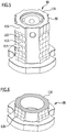
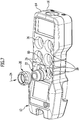
- an advantageous embodiment of an operating device according to the invention is shown schematically and denoted overall by the reference number 10.
- the operating device 10 forms a radio remote control and has a housing 12 with an upper housing part 14 and a lower housing part 16, which are connected to one another in a splash-proof manner.
- the housing 12 accommodates a control and transmission electronics system which is known per se and is not shown in the drawing to achieve a better overview for generating and transmitting a Control signal to a device to be controlled, for example a crane or a lifting device.
- a plurality of identically configured operating devices 18 are arranged on the upper housing part 14 and can be manually operated by the user for the stepless input of control commands.
- the operating devices 18 each include a connecting element 20 and an input device 22.
- the input device 22 forms a preassembled structural unit which is in a Figure 7
- the assembly direction illustrated by the arrow 24 can be inserted into an upper-side recess 26 of the upper housing part 14.
- the recess 26 has a circular cylindrical design and has an upper side wall section 28 which merges via a radially inwardly directed step 30 into a lower side wall section 32, to which a closed bottom wall 34 adjoins.
- the input device 22 has a hood-like, elastically deformable cover part 36 with a central cover opening 38 and a support ring 40.
- the support ring 40 is supported on a top side 42 of a sleeve-like support part 44 which, with an underside 46 facing away from the top side 42, is interposed with a sealing ring 47 sits on step 30.
- the support part 44 forms an intermediate wall 48, to which a guide sleeve 50 adjoins in the direction of the bottom wall 34 of the recess 26.
- the guide sleeve 50 is arranged at a distance from the lower side wall section 32 and, with its free end 52, is at a distance from the bottom wall 34.
- the intermediate wall 48 has a central wall opening 54 which is aligned with the cover opening 38.
- a holding part 56 which is screwed to the intermediate wall 48, is supported on the intermediate wall 48.
- the holding part 56 is designed as a hollow cylinder.
- the input device 22 has a flat key head 58 which rests on the cover part 36.
- a plunger 62 which is aligned coaxially to a longitudinal axis 64 of the input device 22 and with a lower end section 66 facing the bottom wall 34 extends through the central wall opening 54 of the intermediate wall 48.
- a driver 68 is arranged on the lower end section 66 of the plunger 62 and is designed in the form of a driver pin 70 which is oriented perpendicular to the longitudinal axis 64 and which diametrically extends through the lower end section 66.
- the end regions 71, 73 of the driving pin 70 protruding from the lower end section 66 in the radial direction each dip into a curved guide slot 72, 74 of a sleeve-shaped rotary member 76 which extends from the intermediate wall 48 in the direction of the bottom wall 34.
- the rotary member 76 In relation to the longitudinal axis 64, the rotary member 76 is held axially immovable on the guide sleeve 50.
- the rotary member 76 has two holding slots 75, 77 offset axially and circumferentially with respect to the guide slots 72, 74, which extend in the circumferential direction in relation to the longitudinal axis 64 and into each of which a holding pin 79, 81 held stationary on the guide sleeve 50 immersed.
- the rotary member 76 Facing the bottom wall 34, the rotary member 76 has a circular cylindrical receptacle 78 in which a cylindrical permanent magnet 80 polarized laterally, that is to say transversely to the longitudinal axis 64, is held in a rotationally fixed manner.
- the permanent magnet 80 is assigned a magnetic field-sensitive sensor element 82, which is arranged below the bottom wall 34 on a printed circuit board 84 positioned in the housing 12 and via electrical connection lines known per se and therefore not shown in the drawing to achieve a better overview with the one not shown in the drawing illustrated control and transmission electronics of the operating device 10 is in electrical connection.
- a latching member 88 is fixed to an upper end section 86 of the plunger 62 and is designed as a cylindrical latching sleeve 90 in the illustrated embodiment.
- the locking sleeve 90 is penetrated by the plunger 62 in the longitudinal direction.
- the plunger 62 is surrounded by a helical return spring 92, which is supported on the one hand on a radially inwardly directed collar 94 of the locking sleeve 90 and on the other hand on the partition 48.
- the input device 22 forms a pre-assemblable structural unit which can be inserted into the recess 26 in the assembly direction 24.
- the connecting element 20 is used, which is designed in the form of a coupling ring 96 in the illustrated embodiment.
- the coupling ring 96 surrounds the cover part 36 and the key top 58 in the circumferential direction and has an external thread 98 which can be screwed into a complementary internal thread 100 which is arranged on the upper side wall section 28 of the recess 26.
- the user can actuate the key head 58 so that it is linearly displaced along the longitudinal axis 64 together with the plunger 62 and the locking sleeve 90 with elastic deformation of the cover part 36 against the restoring force of the restoring spring 92.
- the linear movement of the plunger 62 is transferred via the driver 68 and the curved guide slots 72, 74 extending in the axial direction and in the circumferential direction into a rotary movement of the rotary member 76 and the permanent magnet 80 fixed to it.
- the axis of rotation of the rotary member 76 coincides with the longitudinal axis 64 of the input device 22.
- An actuation of the key top 58 results in a change in the rotational position of the permanent magnet 80.
- the permanent magnet 80 is magnetized transversely to the longitudinal axis 64, so that a change in the rotational position of the permanent magnet 80 results in a change in the orientation of the magnetic field generated by it relative to the longitudinal axis 64.
- the magnetic field penetrates the bottom wall 34 so that its orientation within the housing 12 can be detected by the sensor element 82.
- the change in the rotational position of the permanent magnet 80 caused by the stroke movement of the key head 58 is thus detected by the magnetic field-sensitive sensor element 82, which then sends a sensor signal to the control and transmission electronics that is dependent on the rotational position of the permanent magnet 80 provides.
- the control and transmission electronics generate a corresponding control signal that is transmitted to the device to be controlled.
- the input device 22 has two diametrically opposite locking elements 102, 104, which are held on the holding part 56 and each have a spherical locking head 106 which is related by means of a locking spring 108 is biased radially inward on the longitudinal axis 64.
- the locking elements 102, 104 are each assigned three locking depressions 110, 112, 114, which are arranged one behind the other in the axial direction on the outside of the locking sleeve 90.
- the latching heads 106 plunge into one of the latching recesses 110, 112, 114 in certain stroke positions, which are predetermined by the position of the latching recesses 110, 112, 114 and thereby give the user tactile feedback on reaching the respective stroke position.
- the latching depressions 110, 112, 114 assigned to each latching element 102, 104 are molded into a running groove 116 which extends in the axial direction along the outside of the latching sleeve 90.
- the shape of the running groove 116 like the shape of the locking depressions 110, 112, 114, is adapted to the spherical shape of the respective plunging locking head 106.
- the running groove 116 has a concave, circular arc-shaped surface contour in the circumferential direction and a wave-shaped surface contour in the axial direction with elevations and detent depressions following one another in the axial direction, on which the detent head 106 slides with linear contact when the key head 58 is moved and thereby provides the user with tactile feedback on the achievement of predetermined stroke positions when the button head 58 is actuated.
- the assembly of the operating devices 18 is very simple. As already mentioned, the respective input device 22 can be inserted as a preassembled structural unit in the assembly direction 24 into one of the recesses 26. Then a coupling ring 96 can be placed on the input device 22 and screwed to the housing 12. It is therefore not necessary to open the housing 12 to assemble the operating devices 18. If one or more input devices 22 are to be exchanged at a later point in time, the exchange can also take place without the housing 12 having to be opened. It is only necessary to loosen the screw connection of the union ring 96, and then the respective input device 22 can be easily removed from the recess 26.
Landscapes
- Engineering & Computer Science (AREA)
- Automation & Control Theory (AREA)
- Physics & Mathematics (AREA)
- General Physics & Mathematics (AREA)
- Mechanical Engineering (AREA)
- Mechanical Control Devices (AREA)
Applications Claiming Priority (2)
| Application Number | Priority Date | Filing Date | Title |
|---|---|---|---|
| DE102016117021.6A DE102016117021A1 (de) | 2016-09-09 | 2016-09-09 | Bediengerät |
| PCT/EP2017/070087 WO2018046213A1 (de) | 2016-09-09 | 2017-08-08 | Bediengerät |
Publications (2)
| Publication Number | Publication Date |
|---|---|
| EP3510465A1 EP3510465A1 (de) | 2019-07-17 |
| EP3510465B1 true EP3510465B1 (de) | 2020-10-28 |
Family
ID=59626605
Family Applications (1)
| Application Number | Title | Priority Date | Filing Date |
|---|---|---|---|
| EP17752095.4A Not-in-force EP3510465B1 (de) | 2016-09-09 | 2017-08-08 | Bediengerät |
Country Status (7)
| Country | Link |
|---|---|
| US (1) | US10775830B2 (da) |
| EP (1) | EP3510465B1 (da) |
| AU (1) | AU2017324050B2 (da) |
| CA (1) | CA3036144C (da) |
| DE (1) | DE102016117021A1 (da) |
| DK (1) | DK3510465T3 (da) |
| WO (1) | WO2018046213A1 (da) |
Families Citing this family (4)
| Publication number | Priority date | Publication date | Assignee | Title |
|---|---|---|---|---|
| DE102016117022A1 (de) * | 2016-09-09 | 2018-03-15 | Nbb Holding Ag | Eingabevorrichtung zum Eingeben eines Steuerbefehls und Bediengerät mit einer derartigen Eingabevorrichtung |
| DE102019133185A1 (de) * | 2019-12-05 | 2021-06-10 | Endress+Hauser Conducta Gmbh+Co. Kg | Elektronisches Gerät |
| JP7008349B2 (ja) * | 2020-03-06 | 2022-01-25 | カネテック株式会社 | マグネットホルダ |
| JP7413603B2 (ja) * | 2021-02-16 | 2024-01-15 | アルプスアルパイン株式会社 | プッシュ式入力装置およびプッシュ式シフタ装置 |
Family Cites Families (42)
| Publication number | Priority date | Publication date | Assignee | Title |
|---|---|---|---|---|
| DE224392C (da) | ||||
| DE828875C (de) * | 1948-10-02 | 1952-01-21 | Carl Baer | Eindruckknopfschalter mit unverzoegerbarer Sprungbewegung |
| DE1165369B (de) | 1959-05-20 | 1964-03-12 | Lorena Soc A Resp Limitata Soc | Druckknopfschalter fuer druckstossgefaehrdete Raeume |
| DE1277982B (de) | 1966-07-27 | 1968-09-19 | Demag Zug Gmbh | Taster oder Tastschalter mit wenigstens zwei einrastbaren Schaltstufen |
| GB1241548A (en) | 1967-11-08 | 1971-08-04 | Norman Robson | Improvements in and relating to control mechanisms |
| US3718786A (en) * | 1971-08-05 | 1973-02-27 | Tri Line Electric Co Inc | Rotary switch assembly |
| DE2216634A1 (de) | 1972-04-07 | 1973-10-18 | Boerge Heidersberger | Tastendruckschalter |
| US3743806A (en) | 1972-05-08 | 1973-07-03 | Korry Mfg Co | Releasable cartridge mounted servomechanism for an operating unit latched to a keeper device on the cartridge thereof |
| FI59649C (fi) | 1977-07-08 | 1981-09-10 | Partek Ab | Regler- och laosningsanordning foer varje hoern som oeppnas av vaedringslucka respektive foenster i fordonstak |
| DE2853810C2 (de) | 1978-12-13 | 1980-12-18 | Siemens Ag, 1000 Berlin Und 8000 Muenchen | Druckknopftaster |
| US4298778A (en) | 1979-01-25 | 1981-11-03 | Beresford Jones Godric P K | Waterproof seal for a push-button |
| US4322711A (en) | 1980-12-19 | 1982-03-30 | Blackstone Industries, Inc. | Foot pedal motor control |
| US4317392A (en) | 1981-03-30 | 1982-03-02 | Perry M. Lane | Ratchet wrench |
| DE3608569A1 (de) | 1986-03-14 | 1987-09-17 | Bbc Brown Boveri & Cie | Betaetigungselement mit einem betaetigungsstoessel fuer explosionsgeschuetztes elektrisches schaltgeraet |
| FR2604559B1 (fr) | 1986-09-26 | 1994-12-02 | Legrand Sa | Dispositif de commande pour materiel electrique antideflagrant |
| US4758692A (en) | 1987-05-19 | 1988-07-19 | Otto Engineering, Inc. | Joystick type control device |
| FR2629258B1 (fr) * | 1988-03-25 | 1995-06-30 | Telemecanique Electrique | Dispositif d'arret d'urgence a commande par cable |
| FR2637037B1 (fr) | 1988-09-23 | 1993-07-09 | Chorin Christian | Dispositif pour transformer un mouvement lineaire en mouvement rotatif avec possibilite de reversibilite, d'efforts et vitesses variables |
| US5345050A (en) | 1993-06-01 | 1994-09-06 | Caterpillar Inc. | Switch actuating assembly |
| DE4330502C1 (de) | 1993-09-09 | 1994-10-13 | Merit Elektrik Gmbh | Schalter mit Druckbetätigung, insbesondere Druck-Druck-Schalter zum Ein-, Aus- oder Umschalten von elektrischen Einrichtungen in Kraftfahrzeugen oder dergleichen |
| DE4412557C3 (de) | 1994-04-11 | 2001-06-13 | Mannesmann Ag | Schaltgerät für Handbetätigung und die Umwandlung eines Betätigungsweges in ein elektrisches Signal |
| DE9407052U1 (de) | 1994-04-28 | 1994-06-30 | Warga, Ewald, 75417 Mühlacker | Schalter, insbesondere Fußschalter |
| US5665947A (en) * | 1995-12-20 | 1997-09-09 | Honeywell, Inc. | Cable actuated switching mechanism with mechanical snap action capibility and broken cable monitoring capability |
| DE19632525C1 (de) | 1996-08-13 | 1997-07-03 | Leica Camera Gmbh | Mehrstufiger Druckschalter für elektronische Geräte |
| FR2769126B1 (fr) * | 1997-09-29 | 1999-12-24 | Valeo Electronique | Commutateur rotatif a poussoir pour tableau de commande |
| US6501458B2 (en) * | 1999-06-30 | 2002-12-31 | Caterpillar Inc | Magnetically coupled input device |
| DE10027446B4 (de) * | 2000-06-02 | 2004-05-27 | ITT Manufacturing Enterprises, Inc., Wilmington | Elektrischer Schalter |
| JP4323301B2 (ja) | 2003-01-30 | 2009-09-02 | アルプス電気株式会社 | プッシュスイッチ装置 |
| DE10304595B3 (de) * | 2003-02-05 | 2004-10-07 | Integrated Electronic Systems !Sys Consulting Gmbh | Schaltvorrichtung |
| DE10319180B4 (de) * | 2003-04-29 | 2007-08-09 | Behr-Hella Thermocontrol Gmbh | Elektrische Einstellvorrichtung |
| DE10331130A1 (de) * | 2003-07-09 | 2005-02-03 | Demag Cranes & Components Gmbh | Schalter für die Handbetätigung von Hebezeugen |
| DE102004053033B3 (de) | 2004-11-03 | 2005-12-08 | Daimlerchrysler Ag | Mechanisches Bewegungsübertragungsorgan |
| DE202006017729U1 (de) | 2006-11-21 | 2008-04-03 | Liebherr-Werk Ehingen Gmbh | Funkfernsteuerung |
| DE102006059822A1 (de) * | 2006-12-11 | 2008-06-12 | Integrated Electronic Systems !Sys Consulting Gmbh | Elektrische Steuereinrichtung |
| DE102007046512A1 (de) | 2007-09-28 | 2009-04-09 | Siemens Ag | Schaltelement zur mechanischen Verbindung mit einem Betätiger |
| DE102008057993B3 (de) * | 2008-11-19 | 2010-01-07 | Demag Cranes & Components Gmbh | Bedienungsgerät für die Handbetätigung von Hebezeugen |
| US8207805B2 (en) * | 2009-03-17 | 2012-06-26 | W. Gessmann Gmbh | Push-button |
| DE102010006826A1 (de) | 2010-02-03 | 2011-08-04 | Horizon Hobby Deutschland GmbH, 25337 | Sender zur Funkfernsteuerung mit einem Basismodul und mindestens einem Wechselmodul |
| DE102012023806A1 (de) | 2012-12-05 | 2014-06-05 | Ulrich Schumann | Handsteuergerät zur Funkfernsteuerung von Bergbaumaschinen |
| DE102013008033A1 (de) * | 2013-05-13 | 2014-11-13 | Sipos Aktorik Gmbh | Stellantrieb |
| DE102014111715A1 (de) * | 2014-08-15 | 2016-02-18 | Hans Heidolph Gmbh & Co. Kg | Laborgerät |
| DE102016117022A1 (de) * | 2016-09-09 | 2018-03-15 | Nbb Holding Ag | Eingabevorrichtung zum Eingeben eines Steuerbefehls und Bediengerät mit einer derartigen Eingabevorrichtung |
-
2016
- 2016-09-09 DE DE102016117021.6A patent/DE102016117021A1/de not_active Withdrawn
-
2017
- 2017-08-08 EP EP17752095.4A patent/EP3510465B1/de not_active Not-in-force
- 2017-08-08 CA CA3036144A patent/CA3036144C/en active Active
- 2017-08-08 DK DK17752095.4T patent/DK3510465T3/da active
- 2017-08-08 WO PCT/EP2017/070087 patent/WO2018046213A1/de not_active Ceased
- 2017-08-08 AU AU2017324050A patent/AU2017324050B2/en not_active Ceased
-
2019
- 2019-02-28 US US16/288,405 patent/US10775830B2/en not_active Expired - Fee Related
Non-Patent Citations (1)
| Title |
|---|
| None * |
Also Published As
| Publication number | Publication date |
|---|---|
| WO2018046213A1 (de) | 2018-03-15 |
| CA3036144C (en) | 2021-04-06 |
| EP3510465A1 (de) | 2019-07-17 |
| AU2017324050B2 (en) | 2020-10-22 |
| DE102016117021A1 (de) | 2018-03-15 |
| AU2017324050A1 (en) | 2019-03-28 |
| DK3510465T3 (da) | 2021-01-11 |
| CA3036144A1 (en) | 2018-03-15 |
| US10775830B2 (en) | 2020-09-15 |
| US20190258286A1 (en) | 2019-08-22 |
Similar Documents
| Publication | Publication Date | Title |
|---|---|---|
| DE69833269T2 (de) | Kontrollvorrichtung zur erzeugung eines variablen signals zur steuerung einer flüssigkeitszufuhr regelnden maschine | |
| DE602004010763T2 (de) | Steuerknüppeleingabegerät | |
| EP2984667B1 (de) | Vorrichtung zur bedienung mehrerer funktionen in einem kraftfahrzeug | |
| EP1901005A2 (de) | Bedienvorrichtung für ein Elektrogerät und Bedienverfahren | |
| DE202015102454U1 (de) | Steuerungsvorrichtung zum Steuern von Einrichtungen per Hand | |
| EP3510465A1 (de) | Bediengerät | |
| WO2018219404A1 (de) | Schliesssystem mit drehbarem stellelement und federelement | |
| EP3510466A1 (de) | Eingabevorrichtung zum eingeben eines steuerbefehls und bediengerät mit einer derartigen eingabevorrichtung | |
| WO2009040012A1 (de) | Bedieneinrichtung für den fokussiertrieb eines mikroskops | |
| EP3375957B1 (de) | Zuhaltevorrichtung | |
| DE102014202474B3 (de) | Brausekopf mit Ventil | |
| DE102017110472B4 (de) | Joystick zum Steuern von Fahrzeug-, Maschinen- oder Anlagenfunktionen | |
| EP3149263B1 (de) | Türgriff für ein kraftfahrzeug | |
| EP0751326A2 (de) | Vorrichtung zur Ueberwachung des Ventilhubs eines Membranventils | |
| EP4000809B1 (de) | Handwerkzeugmaschine mit einer aktivierungseinheit | |
| DE102005001560A1 (de) | Drehsteller für elektrische oder elektronische Geräte in einem Kraftfahrzeug | |
| EP3348718B1 (de) | Betätigungsvorrichtung für ein ventil einer ablaufanordnung für ein becken | |
| DE102005007887B3 (de) | Vorrichtung zur Betätigung einer Sanitärarmatur | |
| EP0586825B1 (de) | Drehknebel | |
| DE202015104756U1 (de) | Schalteinrichtung zum Schalten eines Mehrkupplungsgetriebes | |
| DE19731345A1 (de) | Vorrichtung zur drahtlosen Steuerung | |
| DE202018105378U1 (de) | Halter für einen Magnet, Stellarmaturpositionserfassungseinrichtung und Stellarmatur | |
| EP3367205A1 (de) | Steuer-vorrichtung | |
| EP1021313A1 (de) | Elektrischer hebelschalter | |
| WO1998046521A1 (de) | Zapfhahn |
Legal Events
| Date | Code | Title | Description |
|---|---|---|---|
| STAA | Information on the status of an ep patent application or granted ep patent |
Free format text: STATUS: UNKNOWN |
|
| STAA | Information on the status of an ep patent application or granted ep patent |
Free format text: STATUS: THE INTERNATIONAL PUBLICATION HAS BEEN MADE |
|
| PUAI | Public reference made under article 153(3) epc to a published international application that has entered the european phase |
Free format text: ORIGINAL CODE: 0009012 |
|
| STAA | Information on the status of an ep patent application or granted ep patent |
Free format text: STATUS: REQUEST FOR EXAMINATION WAS MADE |
|
| 17P | Request for examination filed |
Effective date: 20190225 |
|
| AK | Designated contracting states |
Kind code of ref document: A1 Designated state(s): AL AT BE BG CH CY CZ DE DK EE ES FI FR GB GR HR HU IE IS IT LI LT LU LV MC MK MT NL NO PL PT RO RS SE SI SK SM TR |
|
| AX | Request for extension of the european patent |
Extension state: BA ME |
|
| DAV | Request for validation of the european patent (deleted) | ||
| DAX | Request for extension of the european patent (deleted) | ||
| RIC1 | Information provided on ipc code assigned before grant |
Ipc: G05G 25/04 20060101ALI20200330BHEP Ipc: B66C 13/40 20060101ALI20200330BHEP Ipc: G05G 1/02 20060101AFI20200330BHEP |
|
| GRAP | Despatch of communication of intention to grant a patent |
Free format text: ORIGINAL CODE: EPIDOSNIGR1 |
|
| STAA | Information on the status of an ep patent application or granted ep patent |
Free format text: STATUS: GRANT OF PATENT IS INTENDED |
|
| INTG | Intention to grant announced |
Effective date: 20200602 |
|
| GRAS | Grant fee paid |
Free format text: ORIGINAL CODE: EPIDOSNIGR3 |
|
| GRAA | (expected) grant |
Free format text: ORIGINAL CODE: 0009210 |
|
| STAA | Information on the status of an ep patent application or granted ep patent |
Free format text: STATUS: THE PATENT HAS BEEN GRANTED |
|
| AK | Designated contracting states |
Kind code of ref document: B1 Designated state(s): AL AT BE BG CH CY CZ DE DK EE ES FI FR GB GR HR HU IE IS IT LI LT LU LV MC MK MT NL NO PL PT RO RS SE SI SK SM TR |
|
| REG | Reference to a national code |
Ref country code: GB Ref legal event code: FG4D Free format text: NOT ENGLISH |
|
| REG | Reference to a national code |
Ref country code: CH Ref legal event code: EP |
|
| REG | Reference to a national code |
Ref country code: DE Ref legal event code: R096 Ref document number: 502017007955 Country of ref document: DE |
|
| REG | Reference to a national code |
Ref country code: AT Ref legal event code: REF Ref document number: 1328858 Country of ref document: AT Kind code of ref document: T Effective date: 20201115 |
|
| REG | Reference to a national code |
Ref country code: IE Ref legal event code: FG4D Free format text: LANGUAGE OF EP DOCUMENT: GERMAN |
|
| REG | Reference to a national code |
Ref country code: DK Ref legal event code: T3 Effective date: 20210107 |
|
| REG | Reference to a national code |
Ref country code: SE Ref legal event code: TRGR |
|
| REG | Reference to a national code |
Ref country code: NL Ref legal event code: MP Effective date: 20201028 |
|
| PG25 | Lapsed in a contracting state [announced via postgrant information from national office to epo] |
Ref country code: FI Free format text: LAPSE BECAUSE OF FAILURE TO SUBMIT A TRANSLATION OF THE DESCRIPTION OR TO PAY THE FEE WITHIN THE PRESCRIBED TIME-LIMIT Effective date: 20201028 Ref country code: GR Free format text: LAPSE BECAUSE OF FAILURE TO SUBMIT A TRANSLATION OF THE DESCRIPTION OR TO PAY THE FEE WITHIN THE PRESCRIBED TIME-LIMIT Effective date: 20210129 Ref country code: PT Free format text: LAPSE BECAUSE OF FAILURE TO SUBMIT A TRANSLATION OF THE DESCRIPTION OR TO PAY THE FEE WITHIN THE PRESCRIBED TIME-LIMIT Effective date: 20210301 Ref country code: RS Free format text: LAPSE BECAUSE OF FAILURE TO SUBMIT A TRANSLATION OF THE DESCRIPTION OR TO PAY THE FEE WITHIN THE PRESCRIBED TIME-LIMIT Effective date: 20201028 Ref country code: NO Free format text: LAPSE BECAUSE OF FAILURE TO SUBMIT A TRANSLATION OF THE DESCRIPTION OR TO PAY THE FEE WITHIN THE PRESCRIBED TIME-LIMIT Effective date: 20210128 |
|
| REG | Reference to a national code |
Ref country code: LT Ref legal event code: MG4D |
|
| PG25 | Lapsed in a contracting state [announced via postgrant information from national office to epo] |
Ref country code: ES Free format text: LAPSE BECAUSE OF FAILURE TO SUBMIT A TRANSLATION OF THE DESCRIPTION OR TO PAY THE FEE WITHIN THE PRESCRIBED TIME-LIMIT Effective date: 20201028 Ref country code: BG Free format text: LAPSE BECAUSE OF FAILURE TO SUBMIT A TRANSLATION OF THE DESCRIPTION OR TO PAY THE FEE WITHIN THE PRESCRIBED TIME-LIMIT Effective date: 20210128 Ref country code: PL Free format text: LAPSE BECAUSE OF FAILURE TO SUBMIT A TRANSLATION OF THE DESCRIPTION OR TO PAY THE FEE WITHIN THE PRESCRIBED TIME-LIMIT Effective date: 20201028 Ref country code: LV Free format text: LAPSE BECAUSE OF FAILURE TO SUBMIT A TRANSLATION OF THE DESCRIPTION OR TO PAY THE FEE WITHIN THE PRESCRIBED TIME-LIMIT Effective date: 20201028 Ref country code: IS Free format text: LAPSE BECAUSE OF FAILURE TO SUBMIT A TRANSLATION OF THE DESCRIPTION OR TO PAY THE FEE WITHIN THE PRESCRIBED TIME-LIMIT Effective date: 20210228 |
|
| PG25 | Lapsed in a contracting state [announced via postgrant information from national office to epo] |
Ref country code: HR Free format text: LAPSE BECAUSE OF FAILURE TO SUBMIT A TRANSLATION OF THE DESCRIPTION OR TO PAY THE FEE WITHIN THE PRESCRIBED TIME-LIMIT Effective date: 20201028 Ref country code: NL Free format text: LAPSE BECAUSE OF FAILURE TO SUBMIT A TRANSLATION OF THE DESCRIPTION OR TO PAY THE FEE WITHIN THE PRESCRIBED TIME-LIMIT Effective date: 20201028 |
|
| REG | Reference to a national code |
Ref country code: DE Ref legal event code: R097 Ref document number: 502017007955 Country of ref document: DE |
|
| PG25 | Lapsed in a contracting state [announced via postgrant information from national office to epo] |
Ref country code: SK Free format text: LAPSE BECAUSE OF FAILURE TO SUBMIT A TRANSLATION OF THE DESCRIPTION OR TO PAY THE FEE WITHIN THE PRESCRIBED TIME-LIMIT Effective date: 20201028 Ref country code: RO Free format text: LAPSE BECAUSE OF FAILURE TO SUBMIT A TRANSLATION OF THE DESCRIPTION OR TO PAY THE FEE WITHIN THE PRESCRIBED TIME-LIMIT Effective date: 20201028 Ref country code: EE Free format text: LAPSE BECAUSE OF FAILURE TO SUBMIT A TRANSLATION OF THE DESCRIPTION OR TO PAY THE FEE WITHIN THE PRESCRIBED TIME-LIMIT Effective date: 20201028 Ref country code: CZ Free format text: LAPSE BECAUSE OF FAILURE TO SUBMIT A TRANSLATION OF THE DESCRIPTION OR TO PAY THE FEE WITHIN THE PRESCRIBED TIME-LIMIT Effective date: 20201028 Ref country code: LT Free format text: LAPSE BECAUSE OF FAILURE TO SUBMIT A TRANSLATION OF THE DESCRIPTION OR TO PAY THE FEE WITHIN THE PRESCRIBED TIME-LIMIT Effective date: 20201028 Ref country code: SM Free format text: LAPSE BECAUSE OF FAILURE TO SUBMIT A TRANSLATION OF THE DESCRIPTION OR TO PAY THE FEE WITHIN THE PRESCRIBED TIME-LIMIT Effective date: 20201028 |
|
| PLBE | No opposition filed within time limit |
Free format text: ORIGINAL CODE: 0009261 |
|
| STAA | Information on the status of an ep patent application or granted ep patent |
Free format text: STATUS: NO OPPOSITION FILED WITHIN TIME LIMIT |
|
| 26N | No opposition filed |
Effective date: 20210729 |
|
| PG25 | Lapsed in a contracting state [announced via postgrant information from national office to epo] |
Ref country code: AL Free format text: LAPSE BECAUSE OF FAILURE TO SUBMIT A TRANSLATION OF THE DESCRIPTION OR TO PAY THE FEE WITHIN THE PRESCRIBED TIME-LIMIT Effective date: 20201028 |
|
| PG25 | Lapsed in a contracting state [announced via postgrant information from national office to epo] |
Ref country code: SI Free format text: LAPSE BECAUSE OF FAILURE TO SUBMIT A TRANSLATION OF THE DESCRIPTION OR TO PAY THE FEE WITHIN THE PRESCRIBED TIME-LIMIT Effective date: 20201028 |
|
| REG | Reference to a national code |
Ref country code: CH Ref legal event code: PL |
|
| PG25 | Lapsed in a contracting state [announced via postgrant information from national office to epo] |
Ref country code: MC Free format text: LAPSE BECAUSE OF FAILURE TO SUBMIT A TRANSLATION OF THE DESCRIPTION OR TO PAY THE FEE WITHIN THE PRESCRIBED TIME-LIMIT Effective date: 20201028 |
|
| REG | Reference to a national code |
Ref country code: BE Ref legal event code: MM Effective date: 20210831 |
|
| GBPC | Gb: european patent ceased through non-payment of renewal fee |
Effective date: 20210808 |
|
| PG25 | Lapsed in a contracting state [announced via postgrant information from national office to epo] |
Ref country code: LI Free format text: LAPSE BECAUSE OF NON-PAYMENT OF DUE FEES Effective date: 20210831 Ref country code: CH Free format text: LAPSE BECAUSE OF NON-PAYMENT OF DUE FEES Effective date: 20210831 |
|
| PG25 | Lapsed in a contracting state [announced via postgrant information from national office to epo] |
Ref country code: IS Free format text: LAPSE BECAUSE OF FAILURE TO SUBMIT A TRANSLATION OF THE DESCRIPTION OR TO PAY THE FEE WITHIN THE PRESCRIBED TIME-LIMIT Effective date: 20210228 Ref country code: LU Free format text: LAPSE BECAUSE OF NON-PAYMENT OF DUE FEES Effective date: 20210808 |
|
| PG25 | Lapsed in a contracting state [announced via postgrant information from national office to epo] |
Ref country code: IE Free format text: LAPSE BECAUSE OF NON-PAYMENT OF DUE FEES Effective date: 20210808 Ref country code: GB Free format text: LAPSE BECAUSE OF NON-PAYMENT OF DUE FEES Effective date: 20210808 Ref country code: BE Free format text: LAPSE BECAUSE OF NON-PAYMENT OF DUE FEES Effective date: 20210831 |
|
| PGFP | Annual fee paid to national office [announced via postgrant information from national office to epo] |
Ref country code: SE Payment date: 20220627 Year of fee payment: 6 |
|
| PGFP | Annual fee paid to national office [announced via postgrant information from national office to epo] |
Ref country code: FR Payment date: 20220623 Year of fee payment: 6 |
|
| PGFP | Annual fee paid to national office [announced via postgrant information from national office to epo] |
Ref country code: IT Payment date: 20220712 Year of fee payment: 6 Ref country code: DK Payment date: 20220809 Year of fee payment: 6 Ref country code: DE Payment date: 20220629 Year of fee payment: 6 Ref country code: AT Payment date: 20220725 Year of fee payment: 6 |
|
| PG25 | Lapsed in a contracting state [announced via postgrant information from national office to epo] |
Ref country code: CY Free format text: LAPSE BECAUSE OF FAILURE TO SUBMIT A TRANSLATION OF THE DESCRIPTION OR TO PAY THE FEE WITHIN THE PRESCRIBED TIME-LIMIT Effective date: 20201028 |
|
| PG25 | Lapsed in a contracting state [announced via postgrant information from national office to epo] |
Ref country code: HU Free format text: LAPSE BECAUSE OF FAILURE TO SUBMIT A TRANSLATION OF THE DESCRIPTION OR TO PAY THE FEE WITHIN THE PRESCRIBED TIME-LIMIT; INVALID AB INITIO Effective date: 20170808 |
|
| REG | Reference to a national code |
Ref country code: DE Ref legal event code: R119 Ref document number: 502017007955 Country of ref document: DE |
|
| REG | Reference to a national code |
Ref country code: DK Ref legal event code: EBP Effective date: 20230831 |
|
| REG | Reference to a national code |
Ref country code: AT Ref legal event code: MM01 Ref document number: 1328858 Country of ref document: AT Kind code of ref document: T Effective date: 20230808 |
|
| PG25 | Lapsed in a contracting state [announced via postgrant information from national office to epo] |
Ref country code: AT Free format text: LAPSE BECAUSE OF NON-PAYMENT OF DUE FEES Effective date: 20230808 |
|
| PG25 | Lapsed in a contracting state [announced via postgrant information from national office to epo] |
Ref country code: MK Free format text: LAPSE BECAUSE OF FAILURE TO SUBMIT A TRANSLATION OF THE DESCRIPTION OR TO PAY THE FEE WITHIN THE PRESCRIBED TIME-LIMIT Effective date: 20201028 Ref country code: AT Free format text: LAPSE BECAUSE OF NON-PAYMENT OF DUE FEES Effective date: 20230808 |
|
| PG25 | Lapsed in a contracting state [announced via postgrant information from national office to epo] |
Ref country code: SE Free format text: LAPSE BECAUSE OF NON-PAYMENT OF DUE FEES Effective date: 20230809 |
|
| PG25 | Lapsed in a contracting state [announced via postgrant information from national office to epo] |
Ref country code: TR Free format text: LAPSE BECAUSE OF FAILURE TO SUBMIT A TRANSLATION OF THE DESCRIPTION OR TO PAY THE FEE WITHIN THE PRESCRIBED TIME-LIMIT Effective date: 20201028 |
|
| PG25 | Lapsed in a contracting state [announced via postgrant information from national office to epo] |
Ref country code: DK Free format text: LAPSE BECAUSE OF NON-PAYMENT OF DUE FEES Effective date: 20230831 |
|
| PG25 | Lapsed in a contracting state [announced via postgrant information from national office to epo] |
Ref country code: IT Free format text: LAPSE BECAUSE OF NON-PAYMENT OF DUE FEES Effective date: 20230808 Ref country code: FR Free format text: LAPSE BECAUSE OF NON-PAYMENT OF DUE FEES Effective date: 20230831 Ref country code: DK Free format text: LAPSE BECAUSE OF NON-PAYMENT OF DUE FEES Effective date: 20230831 Ref country code: DE Free format text: LAPSE BECAUSE OF NON-PAYMENT OF DUE FEES Effective date: 20240301 |
|
| PG25 | Lapsed in a contracting state [announced via postgrant information from national office to epo] |
Ref country code: MT Free format text: LAPSE BECAUSE OF FAILURE TO SUBMIT A TRANSLATION OF THE DESCRIPTION OR TO PAY THE FEE WITHIN THE PRESCRIBED TIME-LIMIT Effective date: 20201028 |