EP3510614B1 - Ensemble de transformateur avec compensation de rétrécissement - Google Patents
Ensemble de transformateur avec compensation de rétrécissement Download PDFInfo
- Publication number
- EP3510614B1 EP3510614B1 EP17765157.7A EP17765157A EP3510614B1 EP 3510614 B1 EP3510614 B1 EP 3510614B1 EP 17765157 A EP17765157 A EP 17765157A EP 3510614 B1 EP3510614 B1 EP 3510614B1
- Authority
- EP
- European Patent Office
- Prior art keywords
- winding
- pistons
- transformer
- transformer assembly
- windings
- Prior art date
- Legal status (The legal status is an assumption and is not a legal conclusion. Google has not performed a legal analysis and makes no representation as to the accuracy of the status listed.)
- Active
Links
Images


Classifications
-
- H—ELECTRICITY
- H01—ELECTRIC ELEMENTS
- H01F—MAGNETS; INDUCTANCES; TRANSFORMERS; SELECTION OF MATERIALS FOR THEIR MAGNETIC PROPERTIES
- H01F27/00—Details of transformers or inductances, in general
- H01F27/24—Magnetic cores
-
- H—ELECTRICITY
- H01—ELECTRIC ELEMENTS
- H01F—MAGNETS; INDUCTANCES; TRANSFORMERS; SELECTION OF MATERIALS FOR THEIR MAGNETIC PROPERTIES
- H01F27/00—Details of transformers or inductances, in general
- H01F27/28—Coils; Windings; Conductive connections
- H01F27/30—Fastening or clamping coils, windings, or parts thereof together; Fastening or mounting coils or windings on core, casing, or other support
- H01F27/303—Clamping coils, windings or parts thereof together
-
- H—ELECTRICITY
- H01—ELECTRIC ELEMENTS
- H01F—MAGNETS; INDUCTANCES; TRANSFORMERS; SELECTION OF MATERIALS FOR THEIR MAGNETIC PROPERTIES
- H01F27/00—Details of transformers or inductances, in general
- H01F27/28—Coils; Windings; Conductive connections
-
- H—ELECTRICITY
- H01—ELECTRIC ELEMENTS
- H01F—MAGNETS; INDUCTANCES; TRANSFORMERS; SELECTION OF MATERIALS FOR THEIR MAGNETIC PROPERTIES
- H01F41/00—Apparatus or processes specially adapted for manufacturing or assembling magnets, inductances or transformers; Apparatus or processes specially adapted for manufacturing materials characterised by their magnetic properties
- H01F41/02—Apparatus or processes specially adapted for manufacturing or assembling magnets, inductances or transformers; Apparatus or processes specially adapted for manufacturing materials characterised by their magnetic properties for manufacturing cores, coils, or magnets
- H01F41/0206—Manufacturing of magnetic cores by mechanical means
-
- H—ELECTRICITY
- H01—ELECTRIC ELEMENTS
- H01F—MAGNETS; INDUCTANCES; TRANSFORMERS; SELECTION OF MATERIALS FOR THEIR MAGNETIC PROPERTIES
- H01F41/00—Apparatus or processes specially adapted for manufacturing or assembling magnets, inductances or transformers; Apparatus or processes specially adapted for manufacturing materials characterised by their magnetic properties
- H01F41/02—Apparatus or processes specially adapted for manufacturing or assembling magnets, inductances or transformers; Apparatus or processes specially adapted for manufacturing materials characterised by their magnetic properties for manufacturing cores, coils, or magnets
- H01F41/04—Apparatus or processes specially adapted for manufacturing or assembling magnets, inductances or transformers; Apparatus or processes specially adapted for manufacturing materials characterised by their magnetic properties for manufacturing cores, coils, or magnets for manufacturing coils
Definitions
- the present invention relates to transformer assemblies, in particular transformer assemblies for power applications, and for improved methods for producing such transformer assemblies.
- windings are typically exposed to a drying process, mainly to eliminate traces of water from the insulating material. During this process, the insulating material shrinks, thereby leading to a small decrease, inter alia, in the axial length of windings.
- the active part of a traction transformer comprises one or more windings and a core assembly. During manufacturing, this active part is usually clamped with a mechanical, insulating structure composed by pressure plates and beams. These parts may, for example, be made in wood or in polyester based materials reinforced with fibre glass. A number of metallic axial tie rods are typically installed between the beams, the tie rods allowing to maintain a certain pre-stress force on the windings.
- the pre-stress force is applied via the tie rods to the pressure plates and beams.
- the tie rods have to be re-tightened occasionally. This has typically to be repeated a number of times after a certain amount of time, so that the exerted force on the windings is essentially maintained through the entire drying process.
- the assembly of the pressure plates, beams and tie rods must sufficiently be dimensioned, thus resulting in a mass which contributes considerably to the weight of the transformer assembly.
- US 3772627 A describes a shock-absorbing spring clamp for electric induction apparatus
- EP 2530686 A1 describes pressing of transformer windings during active part drying
- DE 2820740 A1 describes a method and apparatus for optimum stabilization of the windings of transformers and chokes.
- a method of compensating the shrinkage during drying or curing of windings in a transformer assembly according to claim 12 is provided.
- a transformer assembly which may be a traction transformer for rail vehicles, or generally a transformer for power conversion applications and for power distribution.
- the assembly comprises a system able to compensate the shrinkage of the winding insulation when drying.
- This system comprises a mobile piston, pushing the windings, and by a pre-stress screw, henceforth also called adjustment screw, imposing a force on the windings.
- a bell is typically also employed to transmit the force from the piston to the metal profiles.
- Spring elements typically in the form of a stack of spring washers, compensate for the variations of the winding dimensions due to the drying and thermal cycles.
- a decrease of the average manufacturing time of a transformer is achieved, in particular a decrease if the assembly time needed for the active part mounting and to the drying process.
- the transformer assembly is typically further used in a productive environment, e.g., in a railway train.
- the above-described system used for the shrinkage compensation is then employed to exert a force on the winding(s) in order to maintain their stability, which is particularly useful in the environment of a railway train or locomotive.
- the spring elements are generally typically configured such that, after the drying or curing is completed, a force exerted on the at least one winding during the further operation of the transformer is dimensioned to be higher than a potentially expanding electromagnetic force of the winding in case of a short circuit condition of the transformer. This ensures that the integrity of the winding is maintained against vibration and shock during normal operation, and is also maintained in case of short circuit.
- the pistons typically move for a distance from about 0,5 mm to about 4 mm, more typically from about 1 mm to about 3 mm during drying or curing.
- the pistons typically move only for a negligible distance in case of a short circuit, as the force exerted by the pistons is configured to be higher than the expanding electromagnetic force of the winding.
- the pistons typically move in a direction towards the metal profiles only during differential thermal expansion of the winding versus the core during operation (e.g. after cold start-up), which occurs within a time constant of some minutes, e.g. 2 minutes to 10 minutes.
- a movement of the pistons towards the metal profiles, away from the center of the winding may occur due to thermal expansion during normal operation, but not due to the electromagnetic forces during a short circuit condition.
- a short circuit condition the counteracting force exerted by the spring elements on the pistons hinders the pistons from being moved by the electromagnetic forces caused by the short circuit condition. If the short circuit condition would persist for a longer time span of e.g. 15 seconds or more, the resulting heating and thermal expansion of the copper might, however, lead to thermal expansion of the winding, which may subsequently lead to a movement of the pistons towards the metal profiles. In practice, however, a short circuit condition is typically terminated latest after a few seconds by a protection mechanism, which is part of the railway train or locomotive.
- the active part of the transformer is generally clamped with metal profiles, which preferably are aluminium extruded profiles. This allows for weight reduction and material cost savings.
- reinforcements are installed along the legs of the transformer and are located between the magnetic core and the windings.
- the reinforcements are in the following also called mechanical connection elements. These reinforcements or mechanical connection elements rigidify the magnetic core and counteract short circuit forces from the windings. The force is transmitted from the windings to the metal profile via the pistons and then, the stress loop is closed through the reinforcements along the leg. A counter-shape on the base of the metal profile(s) is intended for the installation of these reinforcements.
- Fig. 1 a cross-sectional view on a transformer assembly 5 according to embodiments is shown.
- the core 10 has two yokes 12, 14 and two legs 16, 18 (herein, only leg 16 is visible due to the perspective).
- Two windings 20, 22 are provided about the legs 16, 18, whereby only winding 20 is visible in Fig. 1 .
- the windings 20, 22 are insulated by an insulating material 24, which is only schematically shown in Fig. 1 .
- the insulating material 24 may for example be an aramid paper or the like.
- metal profiles 8a, 8b, 8c, 8d are mounted above and below each of the yokes 12, 14.
- the metal profiles 8a, 8b, 8c, 8d extend in parallel to the respective yoke 12, 14 and are mounted to the yokes 12, 14 via bolts 9.
- the metal profiles 8a, 8b, 8c, 8d extend perpendicular to the drawing plane and are thus only visible as a cross-section.
- Pistons 26a, 26b are seated in the metal profiles 8a, 8b, 8c, 8d, wherein the pistons 26a, 26b are movable along their axial direction. Their axial direction is parallel to the longitudinal axis of the winding(s) 20, 22. The pistons 26a, 26b thereby exert a force on the winding 20, 22 in an axial direction of the winding 20, 22. When the winding 20, 22 shrinks in its length dimension (left-right in Fig. 1 ) due to a drying process, the pistons 26a, 26b compensate for this length difference. To this end, the pistons 26a, 26b are mounted with spring elements 40a, 40b.
- spring elements 40a, 40b are typically embodied by a stack of spring washers, such as in the embodiment shown in Fig. 1 .
- the spring elements 40a, 40b may also be embodied by using other means, such as spiral springs, or the like.
- Mechanical connection elements 50a, 50b, 50c, 50d preferably extend in parallel to the windings 20, 22 (and to the legs 16, 18) between the metal profiles 8a, 8b, 8c, 8d which are provided on both ends of the windings 20, 22.
- the mechanical connection elements 50a, 50b, 50c, 50d comprise two elongated metal bars per leg, extending in parallel to each other and in parallel to the legs 16, 18 in a space between the legs 16, 18 and the respective windings 20, 22. Thereby, the elongated metal bars are mounted at their respective ends to at least one of the metal profiles 8a, 8b, 8c, 8d.
- Fig. 2 a part of the transformer assembly is shown, wherein only the windings 20, 22 are left out for illustrational purposes.
- FIG. 2 shows a perspective view on the assembly of Fig. 1 without windings.
- the arrows symbolize the force which the (left out) windings would exert on the metal profiles 8a, 8b, 8c, 8d via the pistons 26a, 26b.
- Fig. 3 the same transformer assembly 5 is shown in complete form, that is, including windings 20, 22, and plates 32b and 32a.
- the metal profiles 8a, 8b, 8c, 8d comprise or consist of aluminium or an aluminium alloy.
- two profiles 8a, 8b; 8c, 8d extend in parallel to each other on opposite sides of each of the yokes 12, 14.
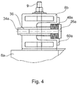
- the pistons 26a, 26b are each seated in the metal profiles 8a, 8b, 8c, 8d via a bell 60a, 60b (not shown in Fig. 1 ).
- the bell 60a, 60b also preferably comprises or consists of aluminium.
- the bell 60a, 60b is intended to transmit the force from the piston 26a, 26b into the metal profile 8a, 8b, 8c, 8d.
- the bell 60a, 60b is particularly useful in the case of extruded metal profiles 8a, 8b, 8c, 8d, as schematically shown in Fig. 4 .
- an adjustment screw 34a, 34b is used for adjusting a force of the piston 26a, 26b onto the respective winding 20, 22.
- the adjustment screw 34a, 34b is seated in an insert 36 having an inner thread.
- the insert 36 is fastened to the bell 60a, preferably also via a thread.
- a plate 32b is typically located between the pistons 26a, 26b and the windings 20, 22, in order to transmit the force from the pistons 26a, 26b to the windings 20, 22.
- the plate 32b comprises or consists of a polymer or a fiber-enforced resin.
- the plate 32b may be ringshaped, such that it substantially covers the cross section of the winding 20, 22.
- the plate 32b may also comprise further functionality, for example oil conducts when the plate 32b is used for transporting/circulating insulating oil into the transformer 5.
- the plate 32b shall be able to withstand the punctual force from the pistons 26a, 26b on one side.
- a further plate 32a which transmits the force from the windings 20, 22 (being pushed by the pistons 26a, 26b from the other side) onto the metal profiles 8a, 8d.
- a total number of four pistons 26a, 26a, 26b, 26b act on each winding 20, 22.
- two pistons per winding are located in metal profile 8b and two pistons per winding are located in metal profile 8c, all on one end of the windings 20, 22.
- the number of pistons per winding may differ. It goes without saying that the skilled person may, based on this disclosure, find other variants to provide the pistons 26a, 26b in the metal profiles 8a, 8b, 8c, 8d, which are regarded to fall under the present disclosure.
- the method of compensating the shrinkage during drying or curing of windings of a transformer assembly comprises: assembling a transformer assembly 5 as described above, and then, during a drying process or a curing process of the windings, applying a force on the winding through pistons.
- the force is obtained by spring elements, and a shrinkage of the windings during drying or curing is compensated by the pistons.
- the transformer assembly may be one of a traction transformer for rolling stock, a distribution transformer, or a power transformer. It is preferably immersed in an insulating fluid, such as mineral oil or oil from organic sources.
Landscapes
- Engineering & Computer Science (AREA)
- Power Engineering (AREA)
- Manufacturing & Machinery (AREA)
- Insulating Of Coils (AREA)
- Fluid-Damping Devices (AREA)
Claims (12)
- Ensemble transformateur (5), comprenant :- un noyau (10) ayant au moins deux culasses (12, 14) et au moins deux jambes (16, 18),- au moins un enroulement (20, 22) fourni autour d'au moins une des jambes (16, 18) du noyau (10), l'au moins un enroulement (20, 22) étant isolé par un matériau isolant (24),- au moins un profilé métallique (8a, 8b, 8c, 8d) par culasse (12, 14), s'étendant parallèlement à la culasse respective (12, 14) et étant monté sur celle-ci,- au moins deux pistons (26a, 26b) logés dans au moins un des profilés métalliques (8a, 8b, 8c, 8d), les pistons (26a, 26b) étant mobiles le long de leur direction axiale qui est parallèle à l'axe longitudinal de l'au moins un enroulement (20, 22), les au moins deux pistons (26a, 26b) exerçant une force sur l'au moins un enroulement (20, 22) dans une direction axiale des enroulements (20, 22),- les pistons (26a, 26b) étant montés avec des éléments de ressort (40a, 40b), caractérisé en ce que- les éléments de ressort (40a, 40b) sont configurés de telle sorte qu'ils compensent les variations des dimensions d'enroulement dues au séchage ou au durcissement et dues aux cycles thermiques, et de telle sorte que, une fois le séchage ou le durcissement terminé, une force exercée sur l'au moins un enroulement est dimensionnée pour être supérieure à une force électromagnétique d'expansion de l'enroulement en cas de condition de court-circuit du transformateur.
- Ensemble transformateur (5) selon la revendication 1, les éléments de ressort (40a, 40b) étant au moins l'un des éléments parmi des rondelles élastiques et des ressorts en spirale.
- Ensemble transformateur (5) selon l'une quelconque des revendications précédentes, comprenant en outre des éléments de liaison mécanique (50a, 50b, 50c, 50d) s'étendant parallèlement aux enroulements (20, 22) entre les profilés métalliques (8a, 8b, 8c, 8d) sur les deux extrémités des enroulements (20, 22).
- Ensemble transformateur (5) selon la revendication 3, les éléments de liaison mécanique (50a, 50b, 50c, 50d) comprenant des barres métalliques allongées s'étendant parallèlement les unes aux autres et parallèlement aux jambes (16, 18) dans un espace entre les jambes (16, 18) et les enroulements respectifs (20, 22), les barres métalliques allongées étant montées au niveau de leurs extrémités respectives sur au moins un des profilés métalliques (8a, 8b, 8c, 8d).
- Ensemble transformateur (5) selon l'une quelconque des revendications précédentes, l'au moins un profilé métallique (8a, 8b, 8c, 8d) par culasse comprenant de l'aluminium.
- Ensemble transformateur (5) selon l'une quelconque des revendications précédentes, ayant deux profilés métalliques (8a, 8b, 8c, 8d) par culasse (12, 14) s'étendant en parallèle sur des côtés opposés de chaque culasse (12, 14).
- Ensemble transformateur (5) selon l'une quelconque des revendications précédentes, les pistons (26a, 26b) étant chacun logés dans les profilés métalliques (8a, 8b, 8c, 8d) par l'intermédiaire d'une cloche (60a, 60b), la cloche (60a, 60b) de préférence comprenant de l'aluminium ou étant constituée d'aluminium.
- Ensemble transformateur (5) selon l'une quelconque des revendications précédentes, une vis de réglage (34a, 34b, 34c, 34d) étant fournie pour chacun des au moins deux pistons (26a, 26b), et la vis de réglage (34a, 34b, 34c, 34d) étant utilisée pour régler une force du piston (26a, 26b).
- Ensemble transformateur (5) selon l'une quelconque des revendications précédentes, une plaque (32b) étant située entre les au moins deux pistons (26a, 26b) et chaque enroulement (20, 22) pour transmettre la force des au moins deux pistons (26a, 26b) aux enroulements (20, 22).
- Ensemble transformateur (5) selon la revendication 10, la plaque (32b) comprenant un polymère, de préférence une résine en fibres renforcée.
- Ensemble transformateur (5) selon l'une quelconque des revendications précédentes, le transformateur étant au moins l'un des éléments parmi : un transformateur de traction pour le matériel roulant, un transformateur de distribution et un transformateur de puissance, et étant de préférence immergé dans un fluide isolant.
- Procédé de compensation du retrait pendant le séchage ou le durcissement des enroulements dans un ensemble transformateur (5), caractérisé par :- l'assemblage d'un ensemble transformateur (5) selon l'une quelconque des revendications 1 à 11,- pendant un processus de séchage ou un processus de durcissement, l'application d'une force sur l'enroulement (20, 22) au moyen des pistons (26a, 26b),- un retrait des enroulements (20, 22) pendant le séchage ou le durcissement est compensé par les pistons (26a, 26b),- les pistons (26a, 26b) étant montés avec des éléments de ressort (40a, 40b) et la force étant obtenue par les éléments de ressort (40a, 40b), et les éléments de ressort (40a, 40b) étant configurés de telle sorte qu'ils compensent les variations des dimensions d'enroulement dues au séchage ou au durcissement et aux cycles thermiques, et de telle sorte que, une fois le séchage ou le durcissement terminé, une force exercée sur l'au moins un enroulement est dimensionnée pour être supérieure à une force électromagnétique d'expansion de l'enroulement en cas d'état de court-circuit du transformateur.
Applications Claiming Priority (2)
| Application Number | Priority Date | Filing Date | Title |
|---|---|---|---|
| EP16188074 | 2016-09-09 | ||
| PCT/EP2017/072507 WO2018046618A1 (fr) | 2016-09-09 | 2017-09-07 | Ensemble transformateur à compensation de retrait |
Publications (2)
| Publication Number | Publication Date |
|---|---|
| EP3510614A1 EP3510614A1 (fr) | 2019-07-17 |
| EP3510614B1 true EP3510614B1 (fr) | 2020-11-04 |
Family
ID=56893868
Family Applications (1)
| Application Number | Title | Priority Date | Filing Date |
|---|---|---|---|
| EP17765157.7A Active EP3510614B1 (fr) | 2016-09-09 | 2017-09-07 | Ensemble de transformateur avec compensation de rétrécissement |
Country Status (5)
| Country | Link |
|---|---|
| US (1) | US11456104B2 (fr) |
| EP (1) | EP3510614B1 (fr) |
| CN (1) | CN109906494B (fr) |
| ES (1) | ES2842956T3 (fr) |
| WO (1) | WO2018046618A1 (fr) |
Families Citing this family (1)
| Publication number | Priority date | Publication date | Assignee | Title |
|---|---|---|---|---|
| USD908614S1 (en) * | 2018-12-10 | 2021-01-26 | Green Motion Sa | Electric charging station |
Family Cites Families (12)
| Publication number | Priority date | Publication date | Assignee | Title |
|---|---|---|---|---|
| US3772627A (en) * | 1972-09-01 | 1973-11-13 | Gen Electric | Shock-absorbing spring clamp for electric induction apparatus |
| DE2820740C2 (de) * | 1978-05-12 | 1985-03-28 | Brown, Boveri & Cie Ag, 6800 Mannheim | Verfahren und Anordnung zum Pressen von Wicklungen für Transformatoren und Drosselspulen |
| FR2820541B1 (fr) * | 2001-02-06 | 2003-04-11 | France Transfo Sa | Systeme de calage d'une bobine dans un transformateur |
| CN101091228B (zh) * | 2004-12-27 | 2010-12-08 | Abb技术有限公司 | 一种用于高压应用的电感应装置 |
| US20070132537A1 (en) * | 2005-12-08 | 2007-06-14 | General Electric Company | Transformer and method of assembly |
| EP2530686B1 (fr) * | 2011-06-01 | 2014-08-06 | ABB Research Ltd. | Pression des enroulements de transformateur durant le séchage de la partie active |
| CN202384172U (zh) * | 2011-12-09 | 2012-08-15 | 常州东芝舒电变压器有限公司 | 变压器线圈压紧装置 |
| CN203966732U (zh) * | 2014-07-21 | 2014-11-26 | 红旗集团温州变压器有限公司 | 干式变压器 |
| CN204028192U (zh) * | 2014-08-13 | 2014-12-17 | 浙江北互互感器有限公司 | 一种防震防噪音的电压互感器 |
| CN204792382U (zh) * | 2015-07-22 | 2015-11-18 | 宁波西博恩新材料科技有限公司 | 一种非晶合金变压器 |
| CN205012978U (zh) * | 2015-10-10 | 2016-02-03 | 陈庆先 | 差步直线井下智能采油装置 |
| US10262785B2 (en) * | 2017-08-24 | 2019-04-16 | Prolec-Ge Internacional, S. De R. L. De C. V. | Press-clamp with clamping force sensor for electric transformer winding |
-
2017
- 2017-09-07 ES ES17765157T patent/ES2842956T3/es active Active
- 2017-09-07 EP EP17765157.7A patent/EP3510614B1/fr active Active
- 2017-09-07 CN CN201780069338.4A patent/CN109906494B/zh active Active
- 2017-09-07 WO PCT/EP2017/072507 patent/WO2018046618A1/fr not_active Ceased
-
2019
- 2019-03-11 US US16/297,854 patent/US11456104B2/en active Active
Non-Patent Citations (1)
| Title |
|---|
| None * |
Also Published As
| Publication number | Publication date |
|---|---|
| CN109906494B (zh) | 2021-04-13 |
| WO2018046618A1 (fr) | 2018-03-15 |
| US11456104B2 (en) | 2022-09-27 |
| US20190206607A1 (en) | 2019-07-04 |
| CN109906494A (zh) | 2019-06-18 |
| ES2842956T3 (es) | 2021-07-15 |
| EP3510614A1 (fr) | 2019-07-17 |
Similar Documents
| Publication | Publication Date | Title |
|---|---|---|
| US9368268B2 (en) | Underfloor transformer | |
| KR101115433B1 (ko) | 고압 전력용 콘덴서 직렬 건식 몰드 리액터 | |
| EP3510614B1 (fr) | Ensemble de transformateur avec compensation de rétrécissement | |
| US6424246B1 (en) | Transformer core and coil support | |
| US7395594B2 (en) | Apparatus and method for the installation of a stator core into a power generator | |
| US12555718B2 (en) | Transformer coil block design for seismic application | |
| US5693996A (en) | Device for holding the bar ends of a stator winding in a dynamoelectric machine | |
| US11062835B2 (en) | Vehicle transformer | |
| KR100805921B1 (ko) | 변압기용 코일지지 프레임 구조 | |
| RU2550085C1 (ru) | Устройство крепления лобовых частей обмотки статора турбогенератора | |
| EP3751588B1 (fr) | Transformateur électrique | |
| EP4687162A1 (fr) | Agencement de bobine et transformateur | |
| EP4687161A1 (fr) | Agencement de bobine, transformateur et procédé | |
| KR102282915B1 (ko) | 돌극형 회전자의 폴 코일용 지그 | |
| US9387606B2 (en) | Vulcanizing press for tire blanks provided with inductors | |
| CN120954860A (zh) | 一种便于组装的干式变压器及组装方法 | |
| EP2325853A1 (fr) | Bobine pour un transformateur | |
| US20190311833A1 (en) | Transformer | |
| JP2010287775A (ja) | 分解輸送変圧器の鉄心輸送方法 | |
| JPS58206109A (ja) | 耐震形変圧器 | |
| ITMI20111716A1 (it) | Bobine di sbarramento per sistemi di trasmissione ad onde convogliate su linee ad alta tensione |
Legal Events
| Date | Code | Title | Description |
|---|---|---|---|
| STAA | Information on the status of an ep patent application or granted ep patent |
Free format text: STATUS: UNKNOWN |
|
| STAA | Information on the status of an ep patent application or granted ep patent |
Free format text: STATUS: THE INTERNATIONAL PUBLICATION HAS BEEN MADE |
|
| PUAI | Public reference made under article 153(3) epc to a published international application that has entered the european phase |
Free format text: ORIGINAL CODE: 0009012 |
|
| STAA | Information on the status of an ep patent application or granted ep patent |
Free format text: STATUS: REQUEST FOR EXAMINATION WAS MADE |
|
| 17P | Request for examination filed |
Effective date: 20190403 |
|
| AK | Designated contracting states |
Kind code of ref document: A1 Designated state(s): AL AT BE BG CH CY CZ DE DK EE ES FI FR GB GR HR HU IE IS IT LI LT LU LV MC MK MT NL NO PL PT RO RS SE SI SK SM TR |
|
| AX | Request for extension of the european patent |
Extension state: BA ME |
|
| DAV | Request for validation of the european patent (deleted) | ||
| DAX | Request for extension of the european patent (deleted) | ||
| GRAP | Despatch of communication of intention to grant a patent |
Free format text: ORIGINAL CODE: EPIDOSNIGR1 |
|
| STAA | Information on the status of an ep patent application or granted ep patent |
Free format text: STATUS: GRANT OF PATENT IS INTENDED |
|
| INTG | Intention to grant announced |
Effective date: 20200417 |
|
| RAP1 | Party data changed (applicant data changed or rights of an application transferred) |
Owner name: ABB SCHWEIZ AG |
|
| RAP1 | Party data changed (applicant data changed or rights of an application transferred) |
Owner name: ABB POWER GRIDS SWITZERLAND AG |
|
| GRAS | Grant fee paid |
Free format text: ORIGINAL CODE: EPIDOSNIGR3 |
|
| GRAA | (expected) grant |
Free format text: ORIGINAL CODE: 0009210 |
|
| STAA | Information on the status of an ep patent application or granted ep patent |
Free format text: STATUS: THE PATENT HAS BEEN GRANTED |
|
| AK | Designated contracting states |
Kind code of ref document: B1 Designated state(s): AL AT BE BG CH CY CZ DE DK EE ES FI FR GB GR HR HU IE IS IT LI LT LU LV MC MK MT NL NO PL PT RO RS SE SI SK SM TR |
|
| REG | Reference to a national code |
Ref country code: GB Ref legal event code: FG4D |
|
| REG | Reference to a national code |
Ref country code: CH Ref legal event code: EP |
|
| REG | Reference to a national code |
Ref country code: AT Ref legal event code: REF Ref document number: 1331880 Country of ref document: AT Kind code of ref document: T Effective date: 20201115 |
|
| REG | Reference to a national code |
Ref country code: IE Ref legal event code: FG4D |
|
| REG | Reference to a national code |
Ref country code: DE Ref legal event code: R096 Ref document number: 602017026915 Country of ref document: DE |
|
| REG | Reference to a national code |
Ref country code: SE Ref legal event code: TRGR |
|
| REG | Reference to a national code |
Ref country code: NO Ref legal event code: T2 Effective date: 20201104 |
|
| REG | Reference to a national code |
Ref country code: NL Ref legal event code: MP Effective date: 20201104 |
|
| REG | Reference to a national code |
Ref country code: NO Ref legal event code: CHAD Owner name: ABB POWER GRIDS SWITZERLAND AG, CH |
|
| PG25 | Lapsed in a contracting state [announced via postgrant information from national office to epo] |
Ref country code: RS Free format text: LAPSE BECAUSE OF FAILURE TO SUBMIT A TRANSLATION OF THE DESCRIPTION OR TO PAY THE FEE WITHIN THE PRESCRIBED TIME-LIMIT Effective date: 20201104 Ref country code: PT Free format text: LAPSE BECAUSE OF FAILURE TO SUBMIT A TRANSLATION OF THE DESCRIPTION OR TO PAY THE FEE WITHIN THE PRESCRIBED TIME-LIMIT Effective date: 20210304 Ref country code: GR Free format text: LAPSE BECAUSE OF FAILURE TO SUBMIT A TRANSLATION OF THE DESCRIPTION OR TO PAY THE FEE WITHIN THE PRESCRIBED TIME-LIMIT Effective date: 20210205 Ref country code: FI Free format text: LAPSE BECAUSE OF FAILURE TO SUBMIT A TRANSLATION OF THE DESCRIPTION OR TO PAY THE FEE WITHIN THE PRESCRIBED TIME-LIMIT Effective date: 20201104 |
|
| PG25 | Lapsed in a contracting state [announced via postgrant information from national office to epo] |
Ref country code: BG Free format text: LAPSE BECAUSE OF FAILURE TO SUBMIT A TRANSLATION OF THE DESCRIPTION OR TO PAY THE FEE WITHIN THE PRESCRIBED TIME-LIMIT Effective date: 20210204 Ref country code: IS Free format text: LAPSE BECAUSE OF FAILURE TO SUBMIT A TRANSLATION OF THE DESCRIPTION OR TO PAY THE FEE WITHIN THE PRESCRIBED TIME-LIMIT Effective date: 20210304 Ref country code: PL Free format text: LAPSE BECAUSE OF FAILURE TO SUBMIT A TRANSLATION OF THE DESCRIPTION OR TO PAY THE FEE WITHIN THE PRESCRIBED TIME-LIMIT Effective date: 20201104 Ref country code: LV Free format text: LAPSE BECAUSE OF FAILURE TO SUBMIT A TRANSLATION OF THE DESCRIPTION OR TO PAY THE FEE WITHIN THE PRESCRIBED TIME-LIMIT Effective date: 20201104 |
|
| REG | Reference to a national code |
Ref country code: ES Ref legal event code: PC2A Owner name: ABB POWER GRIDS SWITZERLAND AG Effective date: 20210525 |
|
| REG | Reference to a national code |
Ref country code: LT Ref legal event code: MG9D |
|
| PG25 | Lapsed in a contracting state [announced via postgrant information from national office to epo] |
Ref country code: HR Free format text: LAPSE BECAUSE OF FAILURE TO SUBMIT A TRANSLATION OF THE DESCRIPTION OR TO PAY THE FEE WITHIN THE PRESCRIBED TIME-LIMIT Effective date: 20201104 |
|
| REG | Reference to a national code |
Ref country code: ES Ref legal event code: FG2A Ref document number: 2842956 Country of ref document: ES Kind code of ref document: T3 Effective date: 20210715 |
|
| PG25 | Lapsed in a contracting state [announced via postgrant information from national office to epo] |
Ref country code: SM Free format text: LAPSE BECAUSE OF FAILURE TO SUBMIT A TRANSLATION OF THE DESCRIPTION OR TO PAY THE FEE WITHIN THE PRESCRIBED TIME-LIMIT Effective date: 20201104 Ref country code: EE Free format text: LAPSE BECAUSE OF FAILURE TO SUBMIT A TRANSLATION OF THE DESCRIPTION OR TO PAY THE FEE WITHIN THE PRESCRIBED TIME-LIMIT Effective date: 20201104 Ref country code: CZ Free format text: LAPSE BECAUSE OF FAILURE TO SUBMIT A TRANSLATION OF THE DESCRIPTION OR TO PAY THE FEE WITHIN THE PRESCRIBED TIME-LIMIT Effective date: 20201104 Ref country code: LT Free format text: LAPSE BECAUSE OF FAILURE TO SUBMIT A TRANSLATION OF THE DESCRIPTION OR TO PAY THE FEE WITHIN THE PRESCRIBED TIME-LIMIT Effective date: 20201104 Ref country code: SK Free format text: LAPSE BECAUSE OF FAILURE TO SUBMIT A TRANSLATION OF THE DESCRIPTION OR TO PAY THE FEE WITHIN THE PRESCRIBED TIME-LIMIT Effective date: 20201104 Ref country code: RO Free format text: LAPSE BECAUSE OF FAILURE TO SUBMIT A TRANSLATION OF THE DESCRIPTION OR TO PAY THE FEE WITHIN THE PRESCRIBED TIME-LIMIT Effective date: 20201104 |
|
| REG | Reference to a national code |
Ref country code: DE Ref legal event code: R097 Ref document number: 602017026915 Country of ref document: DE |
|
| PG25 | Lapsed in a contracting state [announced via postgrant information from national office to epo] |
Ref country code: DK Free format text: LAPSE BECAUSE OF FAILURE TO SUBMIT A TRANSLATION OF THE DESCRIPTION OR TO PAY THE FEE WITHIN THE PRESCRIBED TIME-LIMIT Effective date: 20201104 |
|
| PLBE | No opposition filed within time limit |
Free format text: ORIGINAL CODE: 0009261 |
|
| STAA | Information on the status of an ep patent application or granted ep patent |
Free format text: STATUS: NO OPPOSITION FILED WITHIN TIME LIMIT |
|
| 26N | No opposition filed |
Effective date: 20210805 |
|
| PG25 | Lapsed in a contracting state [announced via postgrant information from national office to epo] |
Ref country code: AL Free format text: LAPSE BECAUSE OF FAILURE TO SUBMIT A TRANSLATION OF THE DESCRIPTION OR TO PAY THE FEE WITHIN THE PRESCRIBED TIME-LIMIT Effective date: 20201104 Ref country code: NL Free format text: LAPSE BECAUSE OF FAILURE TO SUBMIT A TRANSLATION OF THE DESCRIPTION OR TO PAY THE FEE WITHIN THE PRESCRIBED TIME-LIMIT Effective date: 20201104 |
|
| PG25 | Lapsed in a contracting state [announced via postgrant information from national office to epo] |
Ref country code: SI Free format text: LAPSE BECAUSE OF FAILURE TO SUBMIT A TRANSLATION OF THE DESCRIPTION OR TO PAY THE FEE WITHIN THE PRESCRIBED TIME-LIMIT Effective date: 20201104 |
|
| REG | Reference to a national code |
Ref country code: NO Ref legal event code: CHAD Owner name: HITACHI ENERGY SWITZERLAND AG, CH |
|
| REG | Reference to a national code |
Ref country code: BE Ref legal event code: MM Effective date: 20210930 |
|
| REG | Reference to a national code |
Ref country code: ES Ref legal event code: PC2A Owner name: HITACHI ENERGY SWITZERLAND AG Effective date: 20220526 |
|
| PG25 | Lapsed in a contracting state [announced via postgrant information from national office to epo] |
Ref country code: IS Free format text: LAPSE BECAUSE OF FAILURE TO SUBMIT A TRANSLATION OF THE DESCRIPTION OR TO PAY THE FEE WITHIN THE PRESCRIBED TIME-LIMIT Effective date: 20210304 Ref country code: MC Free format text: LAPSE BECAUSE OF FAILURE TO SUBMIT A TRANSLATION OF THE DESCRIPTION OR TO PAY THE FEE WITHIN THE PRESCRIBED TIME-LIMIT Effective date: 20201104 |
|
| REG | Reference to a national code |
Ref country code: DE Ref legal event code: R081 Ref document number: 602017026915 Country of ref document: DE Owner name: HITACHI ENERGY SWITZERLAND AG, CH Free format text: FORMER OWNER: ABB POWER GRIDS SWITZERLAND AG, BADEN, CH Ref country code: DE Ref legal event code: R081 Ref document number: 602017026915 Country of ref document: DE Owner name: HITACHI ENERGY LTD, CH Free format text: FORMER OWNER: ABB POWER GRIDS SWITZERLAND AG, BADEN, CH |
|
| PG25 | Lapsed in a contracting state [announced via postgrant information from national office to epo] |
Ref country code: LU Free format text: LAPSE BECAUSE OF NON-PAYMENT OF DUE FEES Effective date: 20210907 Ref country code: IE Free format text: LAPSE BECAUSE OF NON-PAYMENT OF DUE FEES Effective date: 20210907 Ref country code: BE Free format text: LAPSE BECAUSE OF NON-PAYMENT OF DUE FEES Effective date: 20210930 |
|
| REG | Reference to a national code |
Ref country code: AT Ref legal event code: HC Ref document number: 1331880 Country of ref document: AT Kind code of ref document: T Owner name: HITACHI ENERGY SWITZERLAND AG, CH Effective date: 20220718 |
|
| PG25 | Lapsed in a contracting state [announced via postgrant information from national office to epo] |
Ref country code: CY Free format text: LAPSE BECAUSE OF FAILURE TO SUBMIT A TRANSLATION OF THE DESCRIPTION OR TO PAY THE FEE WITHIN THE PRESCRIBED TIME-LIMIT Effective date: 20201104 |
|
| P01 | Opt-out of the competence of the unified patent court (upc) registered |
Effective date: 20230527 |
|
| PG25 | Lapsed in a contracting state [announced via postgrant information from national office to epo] |
Ref country code: HU Free format text: LAPSE BECAUSE OF FAILURE TO SUBMIT A TRANSLATION OF THE DESCRIPTION OR TO PAY THE FEE WITHIN THE PRESCRIBED TIME-LIMIT; INVALID AB INITIO Effective date: 20170907 |
|
| REG | Reference to a national code |
Ref country code: NO Ref legal event code: CHAD Owner name: HITACHI ENERGY LTD, CH |
|
| REG | Reference to a national code |
Ref country code: DE Ref legal event code: R082 Ref document number: 602017026915 Country of ref document: DE Representative=s name: DENNEMEYER & ASSOCIATES RECHTSANWALTSGESELLSCH, DE Ref country code: DE Ref legal event code: R082 Ref document number: 602017026915 Country of ref document: DE Representative=s name: DENNEMEYER & ASSOCIATES S.A., DE Ref country code: DE Ref legal event code: R081 Ref document number: 602017026915 Country of ref document: DE Owner name: HITACHI ENERGY LTD, CH Free format text: FORMER OWNER: HITACHI ENERGY SWITZERLAND AG, BADEN, CH |
|
| PG25 | Lapsed in a contracting state [announced via postgrant information from national office to epo] |
Ref country code: MK Free format text: LAPSE BECAUSE OF FAILURE TO SUBMIT A TRANSLATION OF THE DESCRIPTION OR TO PAY THE FEE WITHIN THE PRESCRIBED TIME-LIMIT Effective date: 20201104 |
|
| REG | Reference to a national code |
Ref country code: AT Ref legal event code: PC Ref document number: 1331880 Country of ref document: AT Kind code of ref document: T Owner name: HITACHI ENERGY LTD, CH Effective date: 20240416 |
|
| PG25 | Lapsed in a contracting state [announced via postgrant information from national office to epo] |
Ref country code: TR Free format text: LAPSE BECAUSE OF FAILURE TO SUBMIT A TRANSLATION OF THE DESCRIPTION OR TO PAY THE FEE WITHIN THE PRESCRIBED TIME-LIMIT Effective date: 20201104 |
|
| REG | Reference to a national code |
Ref country code: GB Ref legal event code: 732E Free format text: REGISTERED BETWEEN 20240718 AND 20240724 |
|
| PG25 | Lapsed in a contracting state [announced via postgrant information from national office to epo] |
Ref country code: MT Free format text: LAPSE BECAUSE OF FAILURE TO SUBMIT A TRANSLATION OF THE DESCRIPTION OR TO PAY THE FEE WITHIN THE PRESCRIBED TIME-LIMIT Effective date: 20201104 |
|
| REG | Reference to a national code |
Ref country code: ES Ref legal event code: PC2A Owner name: HITACHI ENERGY LTD Effective date: 20240925 |
|
| REG | Reference to a national code |
Ref country code: DE Ref legal event code: R082 Ref document number: 602017026915 Country of ref document: DE Representative=s name: DENNEMEYER & ASSOCIATES RECHTSANWALTSGESELLSCH, DE |
|
| REG | Reference to a national code |
Ref country code: AT Ref legal event code: UEP Ref document number: 1331880 Country of ref document: AT Kind code of ref document: T Effective date: 20201104 |
|
| REG | Reference to a national code |
Ref country code: CH Ref legal event code: U11 Free format text: ST27 STATUS EVENT CODE: U-0-0-U10-U11 (AS PROVIDED BY THE NATIONAL OFFICE) Effective date: 20251001 |
|
| PGFP | Annual fee paid to national office [announced via postgrant information from national office to epo] |
Ref country code: DE Payment date: 20250919 Year of fee payment: 9 |
|
| PGFP | Annual fee paid to national office [announced via postgrant information from national office to epo] |
Ref country code: NO Payment date: 20250923 Year of fee payment: 9 |
|
| PGFP | Annual fee paid to national office [announced via postgrant information from national office to epo] |
Ref country code: IT Payment date: 20250923 Year of fee payment: 9 |
|
| PGFP | Annual fee paid to national office [announced via postgrant information from national office to epo] |
Ref country code: GB Payment date: 20250919 Year of fee payment: 9 |
|
| PGFP | Annual fee paid to national office [announced via postgrant information from national office to epo] |
Ref country code: FR Payment date: 20250922 Year of fee payment: 9 Ref country code: AT Payment date: 20250919 Year of fee payment: 9 |
|
| PGFP | Annual fee paid to national office [announced via postgrant information from national office to epo] |
Ref country code: SE Payment date: 20250918 Year of fee payment: 9 |
|
| PGFP | Annual fee paid to national office [announced via postgrant information from national office to epo] |
Ref country code: CH Payment date: 20251001 Year of fee payment: 9 |
|
| PGFP | Annual fee paid to national office [announced via postgrant information from national office to epo] |
Ref country code: ES Payment date: 20251030 Year of fee payment: 9 |