EP3510694B1 - Dispositif d'entraînement pour un lève-vitre, pourvu d'un élément palier destiné à la fixation d'un stator dans un carter - Google Patents
Dispositif d'entraînement pour un lève-vitre, pourvu d'un élément palier destiné à la fixation d'un stator dans un carter Download PDFInfo
- Publication number
- EP3510694B1 EP3510694B1 EP17764369.9A EP17764369A EP3510694B1 EP 3510694 B1 EP3510694 B1 EP 3510694B1 EP 17764369 A EP17764369 A EP 17764369A EP 3510694 B1 EP3510694 B1 EP 3510694B1
- Authority
- EP
- European Patent Office
- Prior art keywords
- drive
- housing
- stator
- worm
- drive device
- Prior art date
- Legal status (The legal status is an assumption and is not a legal conclusion. Google has not performed a legal analysis and makes no representation as to the accuracy of the status listed.)
- Active
Links
Images







Classifications
-
- E—FIXED CONSTRUCTIONS
- E05—LOCKS; KEYS; WINDOW OR DOOR FITTINGS; SAFES
- E05F—DEVICES FOR MOVING WINGS INTO OPEN OR CLOSED POSITION; CHECKS FOR WINGS; WING FITTINGS NOT OTHERWISE PROVIDED FOR, CONCERNED WITH THE FUNCTIONING OF THE WING
- E05F15/00—Power-operated mechanisms for wings
- E05F15/60—Power-operated mechanisms for wings using electrical actuators
- E05F15/603—Power-operated mechanisms for wings using electrical actuators using rotary electromotors
- E05F15/665—Power-operated mechanisms for wings using electrical actuators using rotary electromotors for vertically-sliding wings
- E05F15/689—Power-operated mechanisms for wings using electrical actuators using rotary electromotors for vertically-sliding wings specially adapted for vehicle windows
- E05F15/697—Motor units therefor, e.g. geared motors
-
- H—ELECTRICITY
- H02—GENERATION; CONVERSION OR DISTRIBUTION OF ELECTRIC POWER
- H02K—DYNAMO-ELECTRIC MACHINES
- H02K1/00—Details of the magnetic circuit
- H02K1/06—Details of the magnetic circuit characterised by the shape, form or construction
- H02K1/12—Stationary parts of the magnetic circuit
- H02K1/18—Means for mounting or fastening magnetic stationary parts on to, or to, the stator structures
- H02K1/187—Means for mounting or fastening magnetic stationary parts on to, or to, the stator structures to inner stators
-
- H—ELECTRICITY
- H02—GENERATION; CONVERSION OR DISTRIBUTION OF ELECTRIC POWER
- H02K—DYNAMO-ELECTRIC MACHINES
- H02K7/00—Arrangements for handling mechanical energy structurally associated with dynamo-electric machines, e.g. structural association with mechanical driving motors or auxiliary dynamo-electric machines
- H02K7/08—Structural association with bearings
- H02K7/081—Structural association with bearings specially adapted for worm gear drives
-
- H—ELECTRICITY
- H02—GENERATION; CONVERSION OR DISTRIBUTION OF ELECTRIC POWER
- H02K—DYNAMO-ELECTRIC MACHINES
- H02K21/00—Synchronous motors having permanent magnets; Synchronous generators having permanent magnets
- H02K21/12—Synchronous motors having permanent magnets; Synchronous generators having permanent magnets with stationary armatures and rotating magnets
- H02K21/22—Synchronous motors having permanent magnets; Synchronous generators having permanent magnets with stationary armatures and rotating magnets with magnets rotating around the armatures, e.g. flywheel magnetos
-
- H—ELECTRICITY
- H02—GENERATION; CONVERSION OR DISTRIBUTION OF ELECTRIC POWER
- H02K—DYNAMO-ELECTRIC MACHINES
- H02K2205/00—Specific aspects not provided for in the other groups of this subclass relating to casings, enclosures, supports
- H02K2205/03—Machines characterised by thrust bearings
-
- H—ELECTRICITY
- H02—GENERATION; CONVERSION OR DISTRIBUTION OF ELECTRIC POWER
- H02K—DYNAMO-ELECTRIC MACHINES
- H02K5/00—Casings; Enclosures; Supports
- H02K5/04—Casings or enclosures characterised by the shape, form or construction thereof
- H02K5/16—Means for supporting bearings, e.g. insulating supports or means for fitting bearings in the bearing-shields
- H02K5/161—Means for supporting bearings, e.g. insulating supports or means for fitting bearings in the bearing-shields radially supporting the rotary shaft at both ends of the rotor
-
- H—ELECTRICITY
- H02—GENERATION; CONVERSION OR DISTRIBUTION OF ELECTRIC POWER
- H02K—DYNAMO-ELECTRIC MACHINES
- H02K7/00—Arrangements for handling mechanical energy structurally associated with dynamo-electric machines, e.g. structural association with mechanical driving motors or auxiliary dynamo-electric machines
- H02K7/10—Structural association with clutches, brakes, gears, pulleys or mechanical starters
- H02K7/116—Structural association with clutches, brakes, gears, pulleys or mechanical starters with gears
- H02K7/1163—Structural association with clutches, brakes, gears, pulleys or mechanical starters with gears where at least two gears have non-parallel axes without having orbital motion
- H02K7/1166—Structural association with clutches, brakes, gears, pulleys or mechanical starters with gears where at least two gears have non-parallel axes without having orbital motion comprising worm and worm-wheel
Definitions
- the invention relates to a drive device for adjusting a cover element of a vehicle, in particular for a window regulator device, according to the preamble of claim 1.
- Such a drive device comprises an output element for adjusting the cover element and a motor unit which has an electric motor with a stator, a rotor and a drive shaft connected to the rotor and rotatable about a shaft axis for driving the output element.
- the motor unit is at least partially enclosed in a drive housing of the drive device.
- the drive device can advantageously be used for adjusting a cover element of a vehicle, in particular for a window regulator device.
- the cover element can be a window pane, a sliding roof, a cargo space cover, a tailgate, a sun blind or also a vehicle door for covering an opening or the like in a vehicle.
- one or more guide rails can be arranged on an assembly carrier of a door module, on each of which a driver coupled to a window pane is guided.
- the driver is coupled to the drive device via a pliable pulling element designed to transmit (exclusively) pulling forces (e.g. a pulling cable), the pulling element being arranged on an output element in the form of a cable drum that the pulling element moves with it when the cable drum rotates winds one end onto the cable drum and unwinds the other end from the cable drum.
- pulling forces e.g. a pulling cable
- a cable drum is arranged on a bearing dome of a drive housing, the drive housing being connected to a support element in the form of a unit carrier via a fastening element in the form of a screw.
- a drive device for a window regulator which is to be mounted, for example, on a carrier element in the form of a unit carrier of a door module on a vehicle side door and is thus to be enclosed within a vehicle side door, should have advantageous operating properties, in particular smooth-running behavior with low vibration excitation on the carrier element and should also have the Use the available installation space efficiently.
- the drive device must provide sufficient torque to ensure reliable adjustment of the adjustment part to be adjusted, for example the window pane, possibly even if the system is difficult to move, for example to run in into a seal or the like.
- the available torque also depends on the size of the electric motor. For example, an electric motor can provide a greater torque with a larger rotor diameter and / or a larger rotor length.
- Out JP 2010 093 943 A a drive device for a steering device is known.
- Out DE 10 2006 047 883 B3 is an electronically commutated electric motor for a Known electric hand tool.
- JP H11 79627 A describes a drive device for a household lift with an electric motor and a harmonic gear (also: "voltage wave gear").
- US 2009 039 725 A1 describes a servo unit with a brushless electric motor and a downstream gear.
- WO 2014 139 727 A2 describes a drive for a transport device, such as a conveyor belt, the drive comprising an external rotor motor, comprising a stator and a rotor, and a gear, comprising a shaft and a drive gear.
- the object of the present invention is to provide a drive device which has favorable operating behavior, provides sufficient torque and can be of compact design.
- stator is connected to a stationary housing section of the drive housing via a bearing element, the bearing element having a bearing opening in which the drive shaft is rotatably supported relative to the stator.
- the bearing element is thus used in two ways.
- the bearing element serves to fix the stator inside the drive housing of the drive device. This makes it possible in particular to design the electric motor as an external rotor motor with a stationary stator located centrally on the inside and a rotor rotating around the stator on the outside, as will be explained below.
- the bearing element also serves to support the drive shaft, for which purpose the bearing element has a bearing opening in which the drive shaft is rotatably mounted relative to the stator.
- the bearing element thus provides a bearing for the drive shaft for rotatable bearing relative to the stator.
- the bearing element can be made of plastic, for example.
- the bearing element can in particular have advantageous sliding properties for bearing the drive shaft.
- the bearing element has a first shaft section which is firmly connected to a stator body of the stator.
- a second shaft section that is axially offset to the first shaft section is fixed to the Housing section connected so that the bearing element creates a fixed connection of the stator with the housing section.
- the rotor is designed as an external rotor rotating radially to the shaft axis outside the stator.
- the electric motor of the motor unit is thus implemented as an external rotor motor.
- the stationary stator is arranged radially inside the rotating rotor. The rotor thus rotates around the stator, which enables the rotor to be designed with a comparatively large diameter, which can bring about a favorable torque behavior of the electric motor.
- the torque of the electric motor increases with the larger diameter. If the diameter of the rotor is thus increased, this can - with the same torque - be used to reduce the size of the electric motor in another direction, in particular in the axial direction, so that the axial length of the electric motor and also of the drive shaft can be reduced.
- the electric motor can in particular be designed as a brushless direct current motor.
- the stator usually has a plurality of pole teeth on a stator body, on which a plurality of stator windings are arranged.
- stator windings can be wound as concentrated windings on the pole teeth.
- wave windings can be used so-called wave windings.
- One or more windings can be arranged on each pole tooth, each winding consisting of several turns which are formed by a winding wire wound around the associated pole tooth.
- the stator windings are energized in an electronically commutated manner in such a way that, for example, three current phases are applied to the windings, so that a rotating field is produced on the stator.
- the rotor has a magnet arrangement with a plurality of permanent magnet poles.
- the magnet arrangement can be formed, for example, by discrete permanent magnets.
- a ring magnet which has a plurality of alternating magnetized magnetic poles offset from one another around the shaft axis.
- bonded or sintered neodymium magnet arrangements can be used.
- a magnet arrangement using cerium (also called cerium, element symbol Ce) as (permanent) is also conceivable and possible. magnetic material. Due to the magnet arrangement, there is a magnetic excitation field on the rotor which, when the electric motor is in operation, interacts with the rotating field of the stator to generate torque on the rotor.
- the stator can have nine pole teeth with stator windings arranged thereon.
- the rotor can for example have a magnet arrangement with six (permanent) magnetic poles (three magnetic pole pairs).
- the rotor has a pole pot which is made, for example, from a ferromagnetic material and can thus provide a magnetic return path for the magnet arrangement arranged on the rotor.
- the rotor is connected to the drive shaft and carries the magnet arrangement, the magnet arrangement being arranged, for example, as a ring magnet within the pole pot.
- the output element is operatively connected to a drive wheel that meshes with the drive shaft.
- the drive shaft carries a drive worm which has worm teeth that mesh with an external toothing of the drive wheel.
- the rotor in particular the pole pot of the rotor, is preferably connected to the drive shaft on a side of the stator facing away from the drive worm.
- the pole pot of the rotor that rotates around the outside of the stator thus surrounds the stator on a side facing away from the drive worm, which enables the stator to be connected to the drive housing via the bearing element on a side facing the drive worm and the drive shaft in close spatial relationship to the drive worm to store over the bearing element.
- the drive housing has a worm housing in which the drive worm is enclosed.
- the worm housing is preferably cylindrical in shape with a diameter that is essentially constant along its axial length, so that the drive worm is rotatably received in the worm housing.
- the worm housing forms the housing section to which the bearing element is connected.
- the bearing element engages in the worm housing and is firmly connected to the worm housing in that the bearing element is pressed into the worm housing. Additionally or alternatively, the bearing element is glued or welded to the worm housing.
- the bearing element is also firmly connected to the stator body of the stator.
- the bearing element can be pressed, welded, glued or otherwise fixed to the stator body with the stator body.
- the bearing element is to be pressed with the worm housing, the bearing element is pressed into the worm housing with a press fit.
- a shoulder can be provided on the worm housing with which the bearing element comes into contact when it is inserted (pressed) into the worm housing, for example via a suitable stop, so that the bearing element is connected State is supported axially on the worm housing.
- the bearing element can assume a defined position relative to the worm housing via a shoulder on the worm housing.
- the bearing element serves to support the drive shaft and can be axially drawn comparatively long, so that a favorable bearing for the drive shaft in the drive housing is created via the bearing element.
- the drive shaft can be mounted in the worm housing via a second bearing element axially offset from the bearing element, this further, second bearing element being arranged, for example, on an end of the drive shaft facing away from the stator and the drive shaft thus being arranged on an end facing away from the stator opposite the Snail housing.
- the further, second bearing element can be designed in the shape of a socket and have the same outer diameter as the shaft section of the first bearing element engaging in the worm housing, so that both the first bearing element and the further, second bearing element can, for example, have a press fit in the worm housing.
- the same outer diameter of the first bearing element and of the further, second bearing element with a constant over the length of the worm housing Inner diameter can bring advantages in the tolerance conditions because the bearing elements experience comparable tolerances in their seat.
- the further, second bearing element can also have crashed axially on a further, second shoulder of the worm housing.
- the further bearing element thus also occupies a defined axial position in the worm housing.
- a stop element can be provided in the worm housing, on which the drive shaft is axially supported at one end (facing away from the stator).
- the run-up element lies, for example, in an end section of the worm housing which can have a reduced inside diameter compared to the section of the worm housing that receives the drive worm.
- the drive shaft can, on the other hand, be axially supported on a cover of a motor pot enclosing the rotor and the stator, with a contact point being formed on the cover that creates an axial bearing for the drive shaft.
- the shaft axis of the drive shaft can be aligned at an oblique angle to an axis of rotation about which the output element can be rotated.
- the shaft axis of the drive shaft extends transversely to the axis of rotation of the output element (in the form of a cable drum). This arrangement of the drive shaft in relation to the output element limits the possibilities of placing the motor unit of the drive device on a carrier element, so that the available installation space is essentially predetermined.
- the shaft axis of the drive shaft can be aligned at an oblique angle to the axis of rotation of the output element. While the shaft axis conventionally has an angle of 90 ° to the axis of rotation of the output element, the shaft axis of the drive shaft now extends at an oblique angle, i.e. an angle ⁇ 90 °, for example an angle in a range between 85 ° and 65 °, for example between 80 ° and 70 °, to the axis of rotation. This provides an additional degree of freedom because it enables the position of the motor unit to be adapted in relation to other components of the drive device, so that an available installation space can be used efficiently.
- the drive worm By inclining the shaft axis of the drive shaft with respect to the axis of rotation of the output element, which preferably also corresponds to the axis of rotation of the drive wheel, the drive worm can also be extended obliquely with respect to the axis of rotation and thus obliquely with respect to the drive wheel.
- the inclined position of the shaft axis can be selected so that the helix angle of the worm toothing corresponds to the angle between the shaft axis and a transverse axis extending transversely (at an angle of 90 °) to the axis of rotation. This enables the toothing of the drive wheel to be designed as straight toothing, which enables a favorable design of the drive wheel with simple, cost-effective manufacture.
- the pitch of a worm gear is generally understood to mean the axial stroke per circumferential length.
- the pitch can be determined, for example, using the axial stroke per revolution divided by the circumferential length per revolution (which results from the length of the path that is obtained when the worm is rolled linearly over one revolution).
- the slope angle results directly from the slope.
- the output element can be, for example, a cable drum rotatable about an axis of rotation for adjusting a tension element that is operatively connected to the cover element and is arranged on a first side of a carrier element, the drive housing being arranged on a second side of the carrier element facing away from the first side.
- the pulling element can be moved in order to move the cover element to be adjusted, for example a window pane.
- the cable drum is here usually arranged in the wet room, for example a vehicle door, while the motor unit is fastened on the other side of the carrier element in a dry room.
- the carrier element provides a wet-dry space separation.
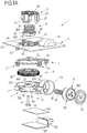
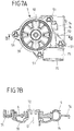
- Figure 1A , 1B to 7A , 7B show an exemplary embodiment of a drive device 1 which can be used, for example, as a drive in an adjusting device for adjusting a window pane, for example a vehicle side door.
- Such an adjusting device in the form of a window regulator shown by way of example in FIG Fig. 12 , has for example a pair of guide rails 11, on each of which a driver 12, which is coupled to a window pane 13, is adjustable.
- Each driver 12 is coupled to a drive device 1 via a pull cable 10, which is designed to transmit (exclusively) tensile forces, the pull cable 10 forming a closed cable loop and, for this purpose, at its ends with a driven element in the form of a cable drum 3 (see FIG example Figure 1A and 1B ) the drive device 1 is connected.
- the traction cable 10 extends from the drive device 1 around pulleys 110 at the lower ends of the guide rails 11 to the drivers 12 and from the drivers 12 around pulleys 111 at the upper ends of the guide rails 11 back to the drive device 10.
- a motor unit of the drive device 1 drives the cable drum 3 in such a way that the pulling cable 10 is wound onto the cable drum 3 at one end and unwound from the cable drum 3 at the other end.
- the rope loop formed by the pull rope 10 shifts without changing the freely extended rope length, which means that the drivers 12 on the guide rails 11 move in the same direction and the window pane 13 is thereby adjusted along the guide rails 11.
- the window lifter is in accordance with the exemplary embodiment Fig. 12 arranged on an assembly carrier 4 of a door module.
- the subframe 4 can be fixed, for example, on an inner door panel of a vehicle door and represents a preassembled unit which can be preassembled with the window regulator arranged on the subframe 4 on the vehicle door.
- the drive device 1 of the embodiment according to Figure 1A , 1B to 7A , 7B is arranged on a surface section 40 of a carrier element 4 implemented, for example, by an assembly carrier of a door module and has a cable output housing 2 arranged on a first side of carrier element 4 and a drive housing 7 arranged on a second side of carrier element 4 facing away from the first side.
- the cable output housing 2 serves to mount the cable drum 3 on the carrier element 4, while the drive housing 7 encloses a drive wheel 6, among other things, which can be driven by a motor unit 8 and is connected to the cable drum 3, so that by rotating the drive wheel 6 the cable drum 3 can be driven.
- the cable drum 3 on the first side of the carrier element 4 is arranged in a wet area of the vehicle door when it is arranged as intended, for example on a vehicle door of a vehicle.
- the drive housing 7, on the other hand, is located in the dry space of the vehicle door. The separation between the wet room and the dry room is established by the carrier element 4, and the interface between the drive wheel 6 and the cable drum 3 must be sealed moisture-tight so that no moisture can get from the wet room into the dry room.
- the cable outlet housing 2 has a base 20, a cylindrical bearing element 22 projecting centrally from the base 20 in the form of a bearing dome and housing sections 21 spaced radially from the bearing element 22 in the form of housing webs extending parallel to the cylindrical bearing element 22.
- the cable drum 3 is rotatably mounted on the bearing element 22 and is surrounded by the cable output housing 2 in such a way that the cable drum 3 is held on the carrier element 4.
- the cable drum 3 has a body 30 and, on the circumferential surface of the body 30, a cable groove 300 formed in the body 30 for receiving the pull cable 10.
- the cable drum 3 is inserted into an opening 41 of the carrier element 4 with a ring gear 31 and is connected to the drive wheel 6 in a rotationally fixed manner, so that a rotational movement of the drive wheel 6 leads to a rotational movement of the cable drum 3.
- the drive housing 7 is attached to the other, second side of the carrier element 4 with a sealing element 5 in between and has a housing pot 70 with a centrally formed therein bearing element 72 in the form of a cylindrical bearing dome which passes through an opening 62 of the drive wheel 6 and rotatably supports the drive wheel 6 in this way.
- a worm housing 74 adjoins the housing pot 70, in which a drive worm 81 rests, which is non-rotatably connected to a drive shaft 800 of an electric motor 80 of the motor unit 8 and meshes with an external toothing 600 of a body 60 of the drive wheel 6 via a worm gear.
- the drive shaft 800 is mounted in the worm housing 74 via a bearing 82 at its end facing away from the electric motor 80.
- the electric motor 80 is located in a motor pot 73 of the drive housing 7, which is closed to the outside via a housing cover 75.
- the drive housing 7 also has an electronics housing 76 in which a circuit board 760 with control electronics arranged thereon is enclosed.
- the electronics housing 76 is closed to the outside via a housing plate 761 with a plug connector 762 arranged thereon for the electrical connection of the electronics of the circuit board 760.
- the drive wheel 6 has, axially protruding from the body 60, a connecting wheel 61 with external toothing 610 formed thereon, which meshes with the ring gear 31 of the cable drum 3 in such a way that an internal toothing 310 of the ring gear 31 (see for example Figure 1B ) is in meshing engagement with the external toothing 610 of the connecting wheel 61.
- the drive wheel 6 and the cable drum 3 are connected to one another in a rotationally fixed manner, so that the cable drum 3 can be rotated by driving the drive wheel 6 on the carrier element 4.
- the cable output housing 2 is attached to the carrier element 4 on the one hand and the drive housing 7 to the carrier element 4 on the other hand.
- the fastening to the carrier element 4 is then carried out in that a fastening element 9 in the form of a screw element is inserted into an engagement opening 721 on the underside of the drive housing 7 in such a way that the fastening element 9 extends through an opening 720 in the bearing element 72 of the drive housing 7 and is central engages in an opening 221 within the bearing element 22 of the cable output housing 2.
- the cable output housing 2 and the drive housing 7 are axially braced to one another on the bearing elements 22, 72 and are fixed on the carrier element 4 via this.
- the cable output housing 2 is attached to the first side of the carrier element 4, so that the cable output housing 2 encloses the cable drum 3 and holds it on the carrier element 4.
- the cable output housing 2 comes with its housing sections 21 spaced radially from the bearing element 22 via foot sections 210 into contact with a contact ring 45 which circumferentially surrounds an opening 41 in the carrier element 4.
- Axially protruding form-fit elements 42 in the form of web-shaped pins are formed on the abutment ring 45, which when the cable output housing 2 is attached to the carrier element 4 with form-fit openings 212 (see FIG Fig. 2 ) come into engagement at the foot sections 210 of the housing sections 21 and in this way create a rotation lock about the axis of rotation D defined by the bearing element 22 between the cable output housing 2 and the carrier element 4.
- Latching recesses 420 are created on the inside of the form-fit elements 42 (see for example Fig. 3 ), into which, when the cable output housing is attached, 2 locking elements 211 in the form of outwardly protruding locking lugs on the housing sections 21 engage. In a pre-assembly position, this snap-in connection holds the cable output housing 2 together with the cable drum 3 enclosed therein on the carrier element 4, even if the drive housing 7 is not yet clamped to the cable output housing 2 via the fastening element 9.
- the latching connection thus simplifies assembly and prevents the cable output housing 2 from falling off when the drive housing 7 has not yet been assembled.
- the cable drum 3 comes over radially protruding support elements 32 on the upper edge of the ring gear 31 (see for example Figure 1A ) with a support ring 46 in support within the opening 41 of the carrier element 4, so that the cable drum 3 cannot slip through the opening 41 in the pre-assembly position and is held on the carrier element 4 via the cable output housing 2.
- the support elements 32 serve in particular to secure the position of the cable drum 3 on the carrier element 4 in the pre-assembly position.
- the cable drum 3 is connected to the drive wheel 6 via the ring gear 31 and is axially fixed between the cable output housing 2 and the drive housing 7.
- axially extending and radially inwardly projecting securing elements 23 are arranged, which face the cable groove 300 on the lateral surface of the body 30 and preferably slide along this lateral surface during operation. These securing elements 23 ensure that the pull rope 10 received in the rope groove 300 cannot jump out of the rope groove 300.
- the drive housing 7 is attached to the other, second side of the carrier element 4 in such a way that the motor pot 73 comes to rest in a recess 44 in the surface section 40 and the worm housing 74 in an adjacent recess 440 in the surface section 40 (see FIG Figure 1A , 1B and 2 ).
- fastening devices 71 in the form of engaging sockets with form-fit openings 710 formed therein come into engagement with form-fit elements 43 in the form of pins protruding from the carrier element 4 on the underside.
- engagement sections 51 are arranged on a sealing ring 50 of the sealing element 5, so that the form-fit engagement of the form-fit elements 43 with the form-fit openings 710 on the fastening devices 71 takes place with the engagement sections 51 interposed. This is used for acoustic decoupling.
- a curved section 52 is formed on the sealing element 5 and comes to lie in the area of the recess 440 for receiving the screw housing 74.
- the curved section 52 forms an intermediate layer between the worm housing 74 and the carrier element 4, so that an acoustic decoupling of the drive housing 7 from the carrier element 4 is also achieved thereover.
- the drive housing 7 is braced to the cable output housing 2 via the fastening element 9, so that the cable output housing 2 and the drive housing 7 to each other and to the Support element 4 are set.
- the fastening element 9 is inserted into the engagement opening 721 within the bearing element 72 of the drive housing 7, so that the fastening element 9 with a shaft 90 extends through the opening 720 on the head of the bearing element 72 and engages in the opening 221 of the bearing element 22 of the cable output housing 2.
- a head 91 of the fastening element 9 comes to rest on the side of the opening 720 facing away from the bearing element 22, so that the cable output housing 2 is braced to the drive housing 7 by screwing the fastening element 9 into the opening 221 within the bearing element 22.
- the bearing element 22 of the cable output housing 2 and the bearing element 72 of the drive housing 7 create a common axis of rotation D for the cable drum 3 on the one hand and the drive wheel 6 on the other, so that the cable drum 3 and the drive wheel 6 can rotate coaxially with one another and together with one another during operation.
- the drive shaft 800 of the electric motor 80 is mounted rotatably about a shaft axis W relative to the drive housing 7.
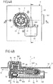
- the electric motor 80 can be seen here by a stator 83, which has a plurality of stator windings 830 (indicated schematically in FIG Figure 4B ) and a rotor 84 carrying a magnet assembly 840 having a plurality of permanent magnet poles is formed.
- the rotor 84 represents an external rotor and rotates radially outside of the stator 83.
- the rotor 84 is connected in a rotationally fixed manner to the drive shaft 800, which is mounted in a sleeve-shaped bearing element 85 such that it can rotate relative to the stator 83.
- the electric motor 80 can be attached to its stator 83 e.g. have six, nine, twelve, fifteen, eighteen, twenty-one or twenty-four pole teeth with stator windings 830 arranged thereon.
- stator windings 830 are energized in an electronically commutated manner, so that a rotating field rotates around the stator 83.
- the rotating field interacts with an excitation field generated by the magnet arrangement 840 (with, for example, four, six, eight, ten, twelve, fourteen or sixteen magnetic poles) on the rotor 84 to generate a torque, so that the rotor 84 rotates around the stator 83 is moved.
- the shaft axis W extends obliquely to the axis of rotation D of the cable drum 3 and the drive wheel 6. This creates an additional degree of freedom in the arrangement of the electric motor 80 on the Carrier element 4, which can contribute to a compact design of the drive device 1.
- Fig. 8 shows a conventional arrangement in which the shaft axis W extends transversely to the axis of rotation D. Because the drive worm 81 is to be arranged at the same height as the drive wheel 6, this means that the electric motor 80 enclosed in the motor pot 73 has a comparatively great height H1 on the second side of the carrier element 4, which takes up the installation space on the second side of the Support element 4 determined. In particular, the height H1 of the motor pot 73 is greater than the height H of the electronics housing 76. The result is a total height H3 of the drive device 1 (measured over the drive housing 7 and the cable output housing 2) that is greater than that over the electronics housing 76 and the cable output housing 2 measured height is H2.
- the shaft axis W extends at an oblique angle to the axis of rotation D, this makes it possible to move the electric motor 80 in the direction of the cable output housing 2 in such a way that the motor pot 73 on the second side of the carrier element 4 does not protrude beyond the electronics housing 76.
- the height of the motor pot 73 on the second side can thus correspond to the height H of the electronics housing 76, so that the motor pot 73 does not require any additional installation space (along the normal direction perpendicular to the carrier element 4).
- the result is a total height H2 of the drive device 1, which is determined (exclusively) by the height of the cable output housing 2 and the electronics housing 76.
- the diameter of the electric motor 80 determined by the rotor 84 designed as an external rotor, can be increased in such a way that the upper edge of the recess 44 is at the same height as the top of the base 20 and thus the total height of the installation space required for the electric motor 80 (determines by the amount of Formation 44 on the first side of the carrier element 4 and the height H of the motor pot 73 on the second side of the carrier element 4) corresponds to the total height H2 of the cable output housing 2 and the electronics housing 76.
- the increase in the rotor diameter 84 makes it possible to reduce the axial length (viewed along the shaft axis W) of the electric motor 80 and the drive shaft 800, so that the increase in diameter makes it possible to reduce the axial length of the electric motor 80 while the torque remains the same.
- the motor pot 73 enclosing the electric motor 80 lies in the recess 44 on the carrier element 4. Because the recess 44 extends into the space of the cable outlet housing 2 on the first side of the carrier element 4 and protrudes from the surface element 40, the motor pot 73 - figuratively speaking and viewed from the second side of the carrier element 4 assigned to the drive housing 7 viewed from - be sunk into the carrier element 4. Together with the oblique alignment of the shaft axis W and the enlargement of the diameter of the electric motor 80, this enables a particularly compact design of the drive device 1.
- the inclination of the shaft axis W relative to the axis of rotation D can be chosen so that the pitch angle ⁇ of the worm toothing 810 of the drive worm 81 corresponds to the angle that the shaft axis W describes to a transverse axis Q pointing transversely to the axis of rotation D, like this in Fig. 11 is shown.
- This enables the external toothing 600 of the drive wheel 6 to be designed as a straight tooth system (with tooth tips extending parallel to the axis of rotation), which - compared to a conventional helical tooth system - makes the drive wheel 6 possible to manufacture easily and inexpensively.
- the inclination of the shaft axis W can thus not only be advantageous for the installation space, but can also enable the drive wheel 6 to be produced simply and inexpensively.
- the shaft axis W describes an angle ⁇ relative to the axis of rotation D.
- the angle ⁇ corresponds to an amount of 90 ° - ⁇ .
- the drive worm 81 can for example be formed in one piece with the drive shaft 800. However, it is also conceivable and possible to arrange the drive worm 81 in a rotationally fixed manner as an additional, separate component on the drive shaft 800.
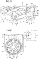
- Figs. 13 to 21 show an embodiment of an electric motor 80 of the motor unit 8 for driving the drive wheel 6 which is enclosed in the housing pot 70 and rotatably mounted on the bearing element 72.
- the electric motor 80 has a stator 83 and a rotor 84 which revolves around the stator 83 and is designed as an external rotor.
- the rotor 84 is connected to the drive shaft 800 on which the drive worm 81 for driving the drive wheel 6 is arranged.
- the stator 83 has a stator body 832, which is formed, for example, as a laminated core by mutually attached sheets and forms a plurality of pole teeth 831 (nine pole teeth 831 in the exemplary embodiment).
- Stator windings 830 are arranged on the pole teeth 831 and, in the exemplary embodiment shown, are designed as concentrated windings. In this case, one or more windings can be arranged on each pole tooth 831, which windings are produced by a winding wire with several turns each wound around the respectively assigned pole tooth 831.
- the stator 83 is firmly connected to the drive housing 7 via a bearing element 85, in that the bearing element 85 engages centrally in the stator body 832 with a first shaft section 850 and in the worm housing 74 with a second shaft section 851 offset axially to the first shaft section 850 (see Fig for example Figure 4B ) is plugged in.
- the stator 83 is firmly connected to the drive housing 7 via the bearing element 85, the shaft sections 850, 851 being fixed in the stator body 832 on the one hand and in the worm housing 74 on the other hand, for example by pressing, gluing, welding or in some other way.
- the bearing element 85 has, for example from a synopsis of Fig. 16 and Figures 19A, 19B As can be seen, a central bearing opening 852 through which the drive shaft 800 engages.
- the drive shaft 800 is thus rotatably mounted in the bearing element 85, the drive shaft 800 additionally being supported at its end facing away from the stator 83 via a bearing element 82 within the worm housing 74 (see, for example, FIG Figure 4B ).
- the bearing element 85 can be made of plastic, for example, and can have advantageous sliding properties for bearing the drive shaft 800.
- the rotor 84 designed as an external rotor has a pole pot 841 which has a magnet arrangement 840 with a plurality of circumferentially offset magnetic poles N, S, as shown schematically in FIG Fig. 21 is shown.
- the magnet arrangement 840 can be designed, for example, as a ring magnet with alternating magnetized (polarized) sections.
- the magnet arrangement 840 has six magnetic poles N, S, as in FIG Fig. 21 shown, which are arranged alternately to one another.
- the pole pot 841 is connected via an end wall 842 to an end of the drive shaft 800 facing away from the drive worm 81, as shown for example in FIG Fig. 16 and Figure 14B can be seen.
- the end wall 842 has a connecting collar 843 into which the drive shaft 800 engages and via which the drive shaft 800 is thus fixed in a rotationally fixed manner to the pole pot 841.
- the pole pot 841 carries the magnet arrangement 840 on the inner side of the circumferential surface facing the stator 83.
- the pole pot 841 is preferably made of a material with ferromagnetic properties, for example a metal material, and advantageously represents a magnetic return path for the magnet arrangement 840.
- the electric motor 80 has an advantageous torque behavior. This makes it possible to reduce the axial length of the electric motor 80 as well as the drive shaft 800 and thus to reduce the installation space of the motor unit 8 in the axial direction.
- the electric motor 80 can also have a different number of pole teeth 831 on the stator 83 and magnetic poles N, S on the rotor 84.
- stator windings 830 on the pole teeth 831 of the rotor 83 are energized in an electronically commutated manner when the drive device 1 is in operation.
- the connection of the stator windings 830 can take place via the bearing element 85, via which lines can be routed from, for example, the electronics housing 76 to the stator windings 830.
- Figures 22 to 25 show a compared to the embodiment according to Figs. 13 to 21 Slightly modified exemplary embodiment of a motor unit 8, in which an electric motor 80 has a rotor 84 designed as an external rotor, which rotates radially outside of a stator 83.
- the rotor 84 has a pole pot 841, which is firmly connected to a drive shaft 800, so that by rotating the rotor 84, the drive shaft 800 is set in a rotational movement and via a drive worm 81 arranged on the drive shaft 800 (which is, for example, integral with the drive shaft 800 is formed) the drive wheel 6 drives.
- the drive shaft 800 is supported in each case via two bearing elements 82, 85 opposite the drive housing 7, namely opposite the worm housing 74.
- the bearing elements 82, 85 provide a rotatable mounting around the shaft axis W for the drive shaft 800.
- This shaft axis W corresponds to the axis of rotation of the rotor 84.
- the bearing element 85 is used, as previously based on the exemplary embodiment according to Figs. 13 to 21 described, also in the embodiment according to Figures 22 to 25 in a synergetic double function to fix the stator 83 with respect to the worm housing 74 and also to support the drive shaft 800.
- the bearing element 85 preferably has the same outer diameter at its shaft section 851 engaging in the worm housing 74 as the further, second bearing element 82. With a constant inner diameter along the length of the worm housing 74, the bearing elements 82, 85 thus experience comparable tolerances within the worm housing 74.
- the second bearing element 85 carrying the stator 83 has a stop 853 formed by circumferentially offset individual projections which, when the bearing element 85 engages in the worm housing 74, is in contact with a shoulder 740 at the entrance of the worm housing 74, so that the stop 853 the axial position of the bearing element 85 with respect to the worm housing 74 is fixed.
- the further, second bearing element 82 rests within the worm housing 74 on a shoulder 741 which is formed at a transition to an end section 742 of the worm housing 74 (with an inner diameter that is smaller than the section of the worm housing 74 that accommodates the drive worm 81), so that also the further, second bearing element 82 is supported axially inside the worm housing 74 and thus assumes a defined axial position within the worm housing 74.
- the drive shaft 800 is supported axially in the worm housing 74 via a stop element 86 which rests in the end section 742 of the worm housing 74.
- the stop element 86 provides an axial bearing for the drive worm 800.
- the drive shaft 800 is axially supported on the cover 75 of the drive housing 7 connected to the motor pot 73, the cover 75 having a contact point 750 protruding towards the drive shaft 800, which provides a defined axial contact for the drive shaft 800 (see in particular Fig. 25 ).
- Axial forces of the drive shaft 800 can thus be absorbed on the cover 75, so that the axial support of the drive shaft 800 on both sides makes it possible to provide an essentially play-free axial bearing for the drive shaft 800 within the worm housing 74 and the motor pot 73 connected to it.
- the cover 75 can, for example, be welded to the motor pot 73, wherein the welding can take place with the cover 75 being braced relative to the motor pot 73 so that the drive shaft 800 can be free of play in the drive housing 7 during assembly.
- a drive device of the type described is in particular not restricted to use on a window lifter, but can also be used to adjust another adjusting element, for example a sliding roof or the like, in a vehicle.
- the drive device can be installed in a simple manner, in particular using a (single) axially bracing fastening element. This results in an assembly in a few assembly steps, which can be simple and inexpensive with reliable fixing of the cable output housing and the drive housing on the carrier element.
Landscapes
- Engineering & Computer Science (AREA)
- Power Engineering (AREA)
- Connection Of Motors, Electrical Generators, Mechanical Devices, And The Like (AREA)
- Power-Operated Mechanisms For Wings (AREA)
- Motor Or Generator Frames (AREA)
- Window Of Vehicle (AREA)
Claims (15)
- Dispositif d'entraînement (1) pour le réglage d'un élément de recouvrement d'un véhicule, en particulier pour dispositif de lève-vitre, avec- un élément de sortie permettant de régler l'élément de recouvrement,- un ensemble moteur (8) comprenant un moteur électrique (80) avec un stator (83), un rotor (84) et un arbre d'entraînement (800) relié au rotor (84) et pouvant tourner autour d'un axe d'arbre (W) pour entraîner l'élément de sortie,- une roue d'entraînement (6), qui est reliée de manière opérationnelle à l'élément de sortie et qui est en prise dentée avec l'arbre d'entraînement (800),- une vis sans fin d'entraînement (81) disposée sur l'arbre d'entraînement (800) et comportant une denture de vis sans fin (810) en prise avec une denture (600) de la roue d'entraînement (6), et- un carter d'entraînement (7), qui entoure au moins partiellement l'ensemble moteur (8) et qui comprend un carter de vis sans fin (74), dans lequel est enfermée la vis sans fin d'entraînement (81),dans lequel le stator (83) est relié à une partie fixe du carter d'entraînement (7) par l'intermédiaire d'un élément de palier (85), l'élément de palier (85) comportant une ouverture de palier (852) dans laquelle l'arbre d'entraînement (800) est monté rotatif par rapport au stator (83)
caractérisé en ce que
l'élément de palier (85) s'engage dans le carter de la vis sans fin (74) et est relié de manière fixe audit carter de la vis sans fin (74) par le fait que l'élément de palier (85) est pressé dans le carter de la vis sans fin (74) et/ou est collé ou soudé au carter de la vis sans fin (74). - Dispositif d'entraînement (1) selon la revendication 1, caractérisé en ce que l'élément de palier (85) comprend une première partie d'arbre (850), qui est reliée de manière fixe à un corps de stator (832) du stator (83), et une deuxième partie d'arbre (851) qui est décalée axialement par rapport à la première partie d'arbre (850) et est reliée de manière fixe à la partie de carter.
- Dispositif d'entraînement (1) selon la revendication 1 ou 2, caractérisé en ce que le rotor (84) est construit comme un rotor externe tournant radialement par rapport à l'axe de l'arbre (W) à l'extérieur du stator (83).
- Dispositif d'entraînement (1) selon les revendications 1 à 3, caractérisé en ce que le moteur électrique (80) est conçu comme un moteur à courant continu sans balais.
- Dispositif d'entraînement (1) selon l'une des revendications précédentes, caractérisé en ce que le stator (83) comprend une pluralité de dents polaires (831) sur lesquelles est disposée une pluralité d'enroulements statoriques (830).
- Dispositif d'entraînement (1) selon l'une des revendications précédentes, caractérisé en ce que le rotor (84) comprend un ensemble magnétique (840) avec une pluralité de pôles magnétiques.
- Dispositif d'entraînement (1) selon l'une des revendications précédentes, caractérisé en ce que le rotor (84) comprend un pot polaire (841), qui est relié à l'arbre d'entraînement (800) et qui supporte l'ensemble magnétique (840).
- Dispositif d'entraînement (1) selon l'une des revendications précédentes, caractérisé en ce que le rotor (84) est relié à l'arbre d'entraînement (800) sur un côté du stator (83) opposé à la vis sans fin d'entraînement (81).
- Dispositif d'entraînement (1) selon l'une des revendications précédentes, caractérisé en ce que l'élément de palier (85) s'appuie axialement sur un premier épaulement (740) du logement de la vis sans fin (74).
- Dispositif d'entraînement (1) selon la revendication 10, caractérisé en ce que l'autre élément de palier (82) est supporté axialement sur un deuxième épaulement (741) du logement de la vis sans fin (74).
- Dispositif d'entraînement (1) selon la revendication 10, caractérisé en ce que l'autre élément de palier (82) est supporté axialement sur un deuxième épaulement (741) du logement de la vis sans fin (74).
- Dispositif d'entraînement (1) selon l'une des revendications précédentes, caractérisé en ce que l'arbre d'entraînement (800) à une extrémité est supporté axialement dans le carter de la vis sans fin (74) par un élément de poussée (86).
- Dispositif d'entraînement (1) selon l'une des revendications précédentes, caractérisé en ce que le rotor (84) et le stator (83) sont enfermés dans un pot de moteur (73) du carter d'entraînement (7), l'arbre d'entraînement (800) étant supporté axialement sur un couvercle (75) du pot de moteur (74).
- Dispositif d'entraînement (1) selon l'une des revendications précédentes, caractérisé en ce que l'axe (W) de l'arbre d'entraînement (800) est orienté selon un angle oblique (a) par rapport à un axe de rotation (D) autour duquel l'élément de sortie peut tourner.
- Dispositif d'entraînement (1) selon l'une des revendications précédentes, caractérisé en ce que l'élément de sortie est un tambour à câble (3) pouvant tourner autour d'un axe de rotation (D) pour le réglage d'un élément de traction (10) en liaison active avec l'élément de recouvrement, qui est disposé sur un premier côté d'un élément porteur (4), le carter d'entraînement (7) étant disposé sur un deuxième côté de l'élément porteur (4) opposé au premier côté.
Applications Claiming Priority (2)
| Application Number | Priority Date | Filing Date | Title |
|---|---|---|---|
| DE102016216888.6A DE102016216888A1 (de) | 2016-09-06 | 2016-09-06 | Antriebsvorrichtung für einen Fensterheber, mit einem Lagerelement zum Fixieren eines Stators in einem Gehäuse |
| PCT/EP2017/072147 WO2018046459A1 (fr) | 2016-09-06 | 2017-09-05 | Dispositif d'entraînement pour un lève-vitre, pourvu d'un élément palier destiné à la fixation d'un stator dans un carter |
Publications (2)
| Publication Number | Publication Date |
|---|---|
| EP3510694A1 EP3510694A1 (fr) | 2019-07-17 |
| EP3510694B1 true EP3510694B1 (fr) | 2020-11-11 |
Family
ID=59811311
Family Applications (1)
| Application Number | Title | Priority Date | Filing Date |
|---|---|---|---|
| EP17764369.9A Active EP3510694B1 (fr) | 2016-09-06 | 2017-09-05 | Dispositif d'entraînement pour un lève-vitre, pourvu d'un élément palier destiné à la fixation d'un stator dans un carter |
Country Status (7)
| Country | Link |
|---|---|
| US (1) | US11828098B2 (fr) |
| EP (1) | EP3510694B1 (fr) |
| JP (1) | JP6844004B2 (fr) |
| CN (1) | CN109863674B (fr) |
| DE (1) | DE102016216888A1 (fr) |
| MA (1) | MA46388A (fr) |
| WO (1) | WO2018046459A1 (fr) |
Cited By (1)
| Publication number | Priority date | Publication date | Assignee | Title |
|---|---|---|---|---|
| WO2024165682A1 (fr) * | 2023-02-09 | 2024-08-15 | Brose Fahrzeugteile Se & Co. Kommanditgesellschaft, Bamberg | Dispositif d'entraînement à moteur électrique sans balais |
Families Citing this family (11)
| Publication number | Priority date | Publication date | Assignee | Title |
|---|---|---|---|---|
| DE102016216877A1 (de) * | 2016-09-06 | 2018-03-08 | Brose Fahrzeugteile Gmbh & Co. Kommanditgesellschaft, Bamberg | Antriebsvorrichtung für einen Fensterheber, mit einem Anschlagsring für eine Seiltrommel |
| DE102019203525A1 (de) * | 2019-03-15 | 2020-09-17 | Brose Fahrzeugteile SE & Co. Kommanditgesellschaft, Würzburg | Antriebsvorrichtung mit einem bürstenlosen Elektromotor |
| DE102020209500A1 (de) * | 2020-07-28 | 2022-02-03 | Brose Fahrzeugteile Se & Co. Kommanditgesellschaft, Bamberg | Antriebsvorrichtung mit einem bürstenlosen Elektromotor |
| JP7413950B2 (ja) * | 2020-08-19 | 2024-01-16 | トヨタ紡織株式会社 | ギア装置 |
| WO2022200313A1 (fr) | 2021-03-24 | 2022-09-29 | Brose Fahrzeugteile Se & Co. Kommanditgesellschaft, Bamberg | Dispositif d'entraînement et ensemble stator associé |
| DE102021205499A1 (de) | 2021-03-24 | 2022-09-29 | Brose Fahrzeugteile Se & Co. Kommanditgesellschaft, Bamberg | Antriebsvorrichtung und Statorbaugruppe hierfür |
| EP4305737B1 (fr) * | 2021-05-05 | 2026-02-25 | Brose Fahrzeugteile SE & Co. Kommanditgesellschaft, Bamberg | Dispositif d'entraînement doté d'un moteur électrique sans balais |
| DE102021209020A1 (de) | 2021-08-17 | 2023-02-23 | Brose Fahrzeugteile Se & Co. Kommanditgesellschaft, Bamberg | Antriebsvorrichtung, insbesondere Verstellantrieb eines Kraftfahrzeugs |
| DE102021212839A1 (de) | 2021-11-16 | 2023-05-17 | Brose Fahrzeugteile Se & Co. Kommanditgesellschaft, Bamberg | Antriebsvorrichtung mit einem bürstenlosen Elektromotor |
| DE102021212840A1 (de) | 2021-11-16 | 2023-05-17 | Brose Fahrzeugteile Se & Co. Kommanditgesellschaft, Bamberg | Antriebsvorrichtung mit einem bürstenlosen Elektromotor |
| DE102023201069A1 (de) | 2023-02-09 | 2024-08-14 | Brose Fahrzeugteile Se & Co. Kommanditgesellschaft, Bamberg | Statorbaugruppe für einen Elektromotor sowie Antriebsvorrichtung |
Family Cites Families (25)
| Publication number | Priority date | Publication date | Assignee | Title |
|---|---|---|---|---|
| US2848218A (en) | 1953-11-24 | 1958-08-19 | Gen Motors Corp | Window regulator |
| US3455174A (en) * | 1967-04-11 | 1969-07-15 | Ferro Mfg Corp | Window regulator motor and transmission housing |
| FR2050946A5 (fr) | 1969-06-30 | 1971-04-02 | Espanola Magnetos Fab | |
| JPS5523711A (en) * | 1978-07-29 | 1980-02-20 | Sony Corp | Rotary electric machine |
| JPS5697082A (en) * | 1979-12-27 | 1981-08-05 | Brose Verwaltung | Electrical driving device |
| DE9209929U1 (de) | 1992-07-23 | 1992-09-24 | Siemens AG, 8000 München | Fensterheber-Antriebseinheit |
| DE29702525U1 (de) * | 1997-02-14 | 1998-06-10 | Robert Bosch Gmbh, 70469 Stuttgart | Vorrichtung zum Verstellen von zu einem Kraftfahrzeug gehörenden Bauteilen |
| DE19733566B4 (de) * | 1997-08-02 | 2005-10-13 | Minebea Co., Ltd. | Spindelmotor mit Hülse |
| JP3924858B2 (ja) | 1997-09-02 | 2007-06-06 | 株式会社明電舎 | ホームエレベータ昇降用駆動装置 |
| DE19926171A1 (de) * | 1999-06-09 | 2000-12-14 | Bosch Gmbh Robert | Elektromotor |
| DE10310186A1 (de) | 2003-03-08 | 2004-09-16 | Valeo Wischersysteme Gmbh | Lager mit Axialabstützung für eine Welle eines elektromotorischen Hilfsantriebs zur Verwendung bei Fahrzeugen sowie elektromotorischer Hilfsantrieb mit einem solchen Lager |
| DE102004044863A1 (de) | 2004-09-14 | 2006-03-30 | Brose Fahrzeugteile Gmbh & Co. Kg, Coburg | Antriebseinheit für Verstelleinrichtungen von Kraftfahrzeugen und Verfahren zu deren Herstellung |
| US7019423B1 (en) * | 2005-02-10 | 2006-03-28 | Sunonwealth Electric Machine Industry Co., Ltd. | Brushless DC motor with tray coupling structure |
| DE102005028815A1 (de) | 2005-06-22 | 2007-01-04 | Robert Bosch Gmbh | Getriebe- Antriebseinheit mit symmetrisch angeordnetem Anschluss-Stecker |
| DE102006047883B3 (de) | 2006-05-06 | 2007-10-18 | Hans Hermann Rottmerhusen | Elektromotor für ein Elektrohandwerkzeug |
| DE112008002124B4 (de) | 2007-08-06 | 2022-01-20 | Delphi Technologies, Inc. | Linearantriebsaktuator für ein bewegliches Fahrzeugpaneel |
| JP2009044818A (ja) * | 2007-08-07 | 2009-02-26 | Nippon Densan Corp | モータ、および、このモータを搭載したサーボユニット |
| JP5203892B2 (ja) * | 2008-02-06 | 2013-06-05 | アスモ株式会社 | 回転軸の組付方法及び回転軸の軸受構造 |
| DE102008043173A1 (de) * | 2008-07-04 | 2010-01-07 | Robert Bosch Gmbh | Getriebe-Antriebseinheit mit einer Selbsthemmvorrichtung |
| JP2010093943A (ja) | 2008-10-08 | 2010-04-22 | Nsk Ltd | ギヤ機構付電動モータ及びこれを使用した電動パワーステアリング装置 |
| DE202010002222U1 (de) | 2010-02-04 | 2011-06-09 | Brose Fahrzeugteile GmbH & Co. Kommanditgesellschaft, Hallstadt, 96103 | Türmodul mit einem akustischen Entkopplungsmittel |
| DE102010013597B3 (de) | 2010-03-31 | 2011-06-01 | Brose Fahrzeugteile Gmbh & Co. Kommanditgesellschaft, Hallstadt | Verfahren zur Steuerung eines Antriebssystems eines Stellelementes eines Kraftfahrzeugs sowie entsprechendes Antriebssystem |
| DE102011005360A1 (de) | 2011-03-10 | 2012-09-13 | Brose Fahrzeugteile Gmbh & Co. Kg, Hallstadt | Antriebseinrichtung mit aktiv gelagerter Antriebswelle |
| CN104321958B (zh) * | 2012-05-25 | 2018-02-06 | 株式会社美姿把 | 电动机 |
| DE102013204436A1 (de) | 2013-03-14 | 2014-09-18 | Krones Ag | Antrieb für eine Transportvorrichtung, Satz von Antrieben und Verfahren zum Antreiben einer Transportvorrichtung |
-
2016
- 2016-09-06 DE DE102016216888.6A patent/DE102016216888A1/de not_active Withdrawn
-
2017
- 2017-09-05 EP EP17764369.9A patent/EP3510694B1/fr active Active
- 2017-09-05 CN CN201780064540.8A patent/CN109863674B/zh active Active
- 2017-09-05 WO PCT/EP2017/072147 patent/WO2018046459A1/fr not_active Ceased
- 2017-09-05 MA MA046388A patent/MA46388A/fr unknown
- 2017-09-05 JP JP2019533679A patent/JP6844004B2/ja active Active
- 2017-09-05 US US16/331,023 patent/US11828098B2/en active Active
Non-Patent Citations (1)
| Title |
|---|
| None * |
Cited By (1)
| Publication number | Priority date | Publication date | Assignee | Title |
|---|---|---|---|---|
| WO2024165682A1 (fr) * | 2023-02-09 | 2024-08-15 | Brose Fahrzeugteile Se & Co. Kommanditgesellschaft, Bamberg | Dispositif d'entraînement à moteur électrique sans balais |
Also Published As
| Publication number | Publication date |
|---|---|
| EP3510694A1 (fr) | 2019-07-17 |
| JP2019527032A (ja) | 2019-09-19 |
| CN109863674B (zh) | 2021-12-21 |
| US20190277079A1 (en) | 2019-09-12 |
| MA46388A (fr) | 2019-07-17 |
| CN109863674A (zh) | 2019-06-07 |
| WO2018046459A1 (fr) | 2018-03-15 |
| US11828098B2 (en) | 2023-11-28 |
| DE102016216888A1 (de) | 2018-03-08 |
| JP6844004B2 (ja) | 2021-03-17 |
Similar Documents
| Publication | Publication Date | Title |
|---|---|---|
| EP3510694B1 (fr) | Dispositif d'entraînement pour un lève-vitre, pourvu d'un élément palier destiné à la fixation d'un stator dans un carter | |
| EP3510692A1 (fr) | Mécanisme d'entraînement pour lève-vitre, comprenant un moteur à rotor extérieur | |
| DE102011054958B4 (de) | Gehäuse eines Stellantriebs zur Aufnahme eines Elektromotors und Baueinheit | |
| EP3510229B1 (fr) | Système de commande pour lève-vitre, doté d'un découplage acoustique | |
| EP3510224B1 (fr) | Système de commande pour lève-vitre | |
| EP3510225B1 (fr) | Dispositif d'entraînement pour un lève-vitre, comprenant une bague de butée pour un tambour de câble | |
| DE102015208496A1 (de) | Bereichsschaltvorrichtung | |
| WO2004042891A1 (fr) | Machine a aimant permanent a entrefer axial | |
| EP1745540A1 (fr) | Moteur electrique et unite d'entrainement de transmission destines a des actionneurs dans un vehicule | |
| WO2018046466A1 (fr) | Mécanisme d'entraînement pour lève-vitre, comprenant un axe d'arbre s'étendant obliquement | |
| EP1099063B1 (fr) | Bloc-moteur | |
| EP1664470A1 (fr) | Systeme d'entrainement pour dispositifs de reglage de vehicules automobiles | |
| EP1145405B1 (fr) | Moto-reducteurs | |
| EP1104378B1 (fr) | Direction assistee par moteur electrique, dotee d'un engrenage planetaire compact | |
| DE102015106834A1 (de) | Schließhilfsantrieb | |
| DE102017009463A1 (de) | Stellantrieb, insbesondere für Kraftfahrzeug-Komfortsysteme | |
| EP1563587B1 (fr) | Dispositif d'entrainement pour dispositifs de reglage de vehicules automobiles | |
| WO2018046507A1 (fr) | Mécanisme d'entraînement pour lève-vitre, comprenant un boîtier de moteur s'engageant dans un élément support | |
| DE112005000322T5 (de) | Motorantriebsvorrichtung | |
| EP1652283A1 (fr) | Unite d'entrainement a engrenage | |
| DE102008042249A1 (de) | Motor-Getriebeeinheit sowie Scheibenwischanlage | |
| DE102010003278A1 (de) | Antriebseinheit für ein Wischersystem mit einer bürstenlosen Gleichstrommaschine | |
| DE102017121222A1 (de) | Scheibenwischermotor | |
| DE102023201069A1 (de) | Statorbaugruppe für einen Elektromotor sowie Antriebsvorrichtung | |
| WO2018046471A1 (fr) | Système d'entraînement pour lève-vitre, muni d'un élément palier servant au montage d'un élément de transmission |
Legal Events
| Date | Code | Title | Description |
|---|---|---|---|
| STAA | Information on the status of an ep patent application or granted ep patent |
Free format text: STATUS: UNKNOWN |
|
| STAA | Information on the status of an ep patent application or granted ep patent |
Free format text: STATUS: THE INTERNATIONAL PUBLICATION HAS BEEN MADE |
|
| PUAI | Public reference made under article 153(3) epc to a published international application that has entered the european phase |
Free format text: ORIGINAL CODE: 0009012 |
|
| STAA | Information on the status of an ep patent application or granted ep patent |
Free format text: STATUS: REQUEST FOR EXAMINATION WAS MADE |
|
| 17P | Request for examination filed |
Effective date: 20190408 |
|
| AK | Designated contracting states |
Kind code of ref document: A1 Designated state(s): AL AT BE BG CH CY CZ DE DK EE ES FI FR GB GR HR HU IE IS IT LI LT LU LV MC MK MT NL NO PL PT RO RS SE SI SK SM TR |
|
| AX | Request for extension of the european patent |
Extension state: BA ME |
|
| RAP1 | Party data changed (applicant data changed or rights of an application transferred) |
Owner name: BROSE FAHRZEUGTEILE SE & CO. KOMMANDITGESELLSCHAFT, WUERZBURG |
|
| GRAP | Despatch of communication of intention to grant a patent |
Free format text: ORIGINAL CODE: EPIDOSNIGR1 |
|
| STAA | Information on the status of an ep patent application or granted ep patent |
Free format text: STATUS: GRANT OF PATENT IS INTENDED |
|
| INTG | Intention to grant announced |
Effective date: 20200602 |
|
| GRAS | Grant fee paid |
Free format text: ORIGINAL CODE: EPIDOSNIGR3 |
|
| GRAA | (expected) grant |
Free format text: ORIGINAL CODE: 0009210 |
|
| STAA | Information on the status of an ep patent application or granted ep patent |
Free format text: STATUS: THE PATENT HAS BEEN GRANTED |
|
| AK | Designated contracting states |
Kind code of ref document: B1 Designated state(s): AL AT BE BG CH CY CZ DE DK EE ES FI FR GB GR HR HU IE IS IT LI LT LU LV MC MK MT NL NO PL PT RO RS SE SI SK SM TR |
|
| AX | Request for extension of the european patent |
Extension state: BA ME |
|
| REG | Reference to a national code |
Ref country code: GB Ref legal event code: FG4D Free format text: NOT ENGLISH |
|
| REG | Reference to a national code |
Ref country code: CH Ref legal event code: EP |
|
| REG | Reference to a national code |
Ref country code: AT Ref legal event code: REF Ref document number: 1334388 Country of ref document: AT Kind code of ref document: T Effective date: 20201115 |
|
| REG | Reference to a national code |
Ref country code: DE Ref legal event code: R096 Ref document number: 502017008177 Country of ref document: DE |
|
| REG | Reference to a national code |
Ref country code: IE Ref legal event code: FG4D Free format text: LANGUAGE OF EP DOCUMENT: GERMAN |
|
| REG | Reference to a national code |
Ref country code: NL Ref legal event code: MP Effective date: 20201111 |
|
| PG25 | Lapsed in a contracting state [announced via postgrant information from national office to epo] |
Ref country code: FI Free format text: LAPSE BECAUSE OF FAILURE TO SUBMIT A TRANSLATION OF THE DESCRIPTION OR TO PAY THE FEE WITHIN THE PRESCRIBED TIME-LIMIT Effective date: 20201111 Ref country code: GR Free format text: LAPSE BECAUSE OF FAILURE TO SUBMIT A TRANSLATION OF THE DESCRIPTION OR TO PAY THE FEE WITHIN THE PRESCRIBED TIME-LIMIT Effective date: 20210212 Ref country code: RS Free format text: LAPSE BECAUSE OF FAILURE TO SUBMIT A TRANSLATION OF THE DESCRIPTION OR TO PAY THE FEE WITHIN THE PRESCRIBED TIME-LIMIT Effective date: 20201111 Ref country code: PT Free format text: LAPSE BECAUSE OF FAILURE TO SUBMIT A TRANSLATION OF THE DESCRIPTION OR TO PAY THE FEE WITHIN THE PRESCRIBED TIME-LIMIT Effective date: 20210311 Ref country code: NO Free format text: LAPSE BECAUSE OF FAILURE TO SUBMIT A TRANSLATION OF THE DESCRIPTION OR TO PAY THE FEE WITHIN THE PRESCRIBED TIME-LIMIT Effective date: 20210211 |
|
| REG | Reference to a national code |
Ref country code: DE Ref legal event code: R081 Ref document number: 502017008177 Country of ref document: DE Owner name: BROSE FAHRZEUGTEILE SE & CO. KOMMANDITGESELLSC, DE Free format text: FORMER OWNER: BROSE FAHRZEUGTEILE SE & CO. KOMMANDITGESELLSCHAFT, WUERZBURG, 97076 WUERZBURG, DE |
|
| PG25 | Lapsed in a contracting state [announced via postgrant information from national office to epo] |
Ref country code: BG Free format text: LAPSE BECAUSE OF FAILURE TO SUBMIT A TRANSLATION OF THE DESCRIPTION OR TO PAY THE FEE WITHIN THE PRESCRIBED TIME-LIMIT Effective date: 20210211 Ref country code: PL Free format text: LAPSE BECAUSE OF FAILURE TO SUBMIT A TRANSLATION OF THE DESCRIPTION OR TO PAY THE FEE WITHIN THE PRESCRIBED TIME-LIMIT Effective date: 20201111 Ref country code: IS Free format text: LAPSE BECAUSE OF FAILURE TO SUBMIT A TRANSLATION OF THE DESCRIPTION OR TO PAY THE FEE WITHIN THE PRESCRIBED TIME-LIMIT Effective date: 20210311 Ref country code: LV Free format text: LAPSE BECAUSE OF FAILURE TO SUBMIT A TRANSLATION OF THE DESCRIPTION OR TO PAY THE FEE WITHIN THE PRESCRIBED TIME-LIMIT Effective date: 20201111 Ref country code: SE Free format text: LAPSE BECAUSE OF FAILURE TO SUBMIT A TRANSLATION OF THE DESCRIPTION OR TO PAY THE FEE WITHIN THE PRESCRIBED TIME-LIMIT Effective date: 20201111 |
|
| REG | Reference to a national code |
Ref country code: LT Ref legal event code: MG9D |
|
| PG25 | Lapsed in a contracting state [announced via postgrant information from national office to epo] |
Ref country code: HR Free format text: LAPSE BECAUSE OF FAILURE TO SUBMIT A TRANSLATION OF THE DESCRIPTION OR TO PAY THE FEE WITHIN THE PRESCRIBED TIME-LIMIT Effective date: 20201111 |
|
| PG25 | Lapsed in a contracting state [announced via postgrant information from national office to epo] |
Ref country code: SK Free format text: LAPSE BECAUSE OF FAILURE TO SUBMIT A TRANSLATION OF THE DESCRIPTION OR TO PAY THE FEE WITHIN THE PRESCRIBED TIME-LIMIT Effective date: 20201111 Ref country code: RO Free format text: LAPSE BECAUSE OF FAILURE TO SUBMIT A TRANSLATION OF THE DESCRIPTION OR TO PAY THE FEE WITHIN THE PRESCRIBED TIME-LIMIT Effective date: 20201111 Ref country code: SM Free format text: LAPSE BECAUSE OF FAILURE TO SUBMIT A TRANSLATION OF THE DESCRIPTION OR TO PAY THE FEE WITHIN THE PRESCRIBED TIME-LIMIT Effective date: 20201111 Ref country code: LT Free format text: LAPSE BECAUSE OF FAILURE TO SUBMIT A TRANSLATION OF THE DESCRIPTION OR TO PAY THE FEE WITHIN THE PRESCRIBED TIME-LIMIT Effective date: 20201111 Ref country code: EE Free format text: LAPSE BECAUSE OF FAILURE TO SUBMIT A TRANSLATION OF THE DESCRIPTION OR TO PAY THE FEE WITHIN THE PRESCRIBED TIME-LIMIT Effective date: 20201111 Ref country code: CZ Free format text: LAPSE BECAUSE OF FAILURE TO SUBMIT A TRANSLATION OF THE DESCRIPTION OR TO PAY THE FEE WITHIN THE PRESCRIBED TIME-LIMIT Effective date: 20201111 |
|
| REG | Reference to a national code |
Ref country code: DE Ref legal event code: R097 Ref document number: 502017008177 Country of ref document: DE |
|
| PG25 | Lapsed in a contracting state [announced via postgrant information from national office to epo] |
Ref country code: DK Free format text: LAPSE BECAUSE OF FAILURE TO SUBMIT A TRANSLATION OF THE DESCRIPTION OR TO PAY THE FEE WITHIN THE PRESCRIBED TIME-LIMIT Effective date: 20201111 |
|
| VS25 | Lapsed in a validation state [announced via postgrant information from nat. office to epo] |
Ref country code: MD Free format text: LAPSE BECAUSE OF FAILURE TO SUBMIT A TRANSLATION OF THE DESCRIPTION OR TO PAY THE FEE WITHIN THE PRESCRIBED TIME-LIMIT Effective date: 20201111 |
|
| PLBE | No opposition filed within time limit |
Free format text: ORIGINAL CODE: 0009261 |
|
| STAA | Information on the status of an ep patent application or granted ep patent |
Free format text: STATUS: NO OPPOSITION FILED WITHIN TIME LIMIT |
|
| 26N | No opposition filed |
Effective date: 20210812 |
|
| PG25 | Lapsed in a contracting state [announced via postgrant information from national office to epo] |
Ref country code: AL Free format text: LAPSE BECAUSE OF FAILURE TO SUBMIT A TRANSLATION OF THE DESCRIPTION OR TO PAY THE FEE WITHIN THE PRESCRIBED TIME-LIMIT Effective date: 20201111 Ref country code: NL Free format text: LAPSE BECAUSE OF FAILURE TO SUBMIT A TRANSLATION OF THE DESCRIPTION OR TO PAY THE FEE WITHIN THE PRESCRIBED TIME-LIMIT Effective date: 20201111 Ref country code: IT Free format text: LAPSE BECAUSE OF FAILURE TO SUBMIT A TRANSLATION OF THE DESCRIPTION OR TO PAY THE FEE WITHIN THE PRESCRIBED TIME-LIMIT Effective date: 20201111 |
|
| PG25 | Lapsed in a contracting state [announced via postgrant information from national office to epo] |
Ref country code: SI Free format text: LAPSE BECAUSE OF FAILURE TO SUBMIT A TRANSLATION OF THE DESCRIPTION OR TO PAY THE FEE WITHIN THE PRESCRIBED TIME-LIMIT Effective date: 20201111 |
|
| PG25 | Lapsed in a contracting state [announced via postgrant information from national office to epo] |
Ref country code: ES Free format text: LAPSE BECAUSE OF FAILURE TO SUBMIT A TRANSLATION OF THE DESCRIPTION OR TO PAY THE FEE WITHIN THE PRESCRIBED TIME-LIMIT Effective date: 20201111 |
|
| REG | Reference to a national code |
Ref country code: CH Ref legal event code: PL |
|
| REG | Reference to a national code |
Ref country code: BE Ref legal event code: MM Effective date: 20210930 |
|
| PG25 | Lapsed in a contracting state [announced via postgrant information from national office to epo] |
Ref country code: IS Free format text: LAPSE BECAUSE OF FAILURE TO SUBMIT A TRANSLATION OF THE DESCRIPTION OR TO PAY THE FEE WITHIN THE PRESCRIBED TIME-LIMIT Effective date: 20210311 Ref country code: MC Free format text: LAPSE BECAUSE OF FAILURE TO SUBMIT A TRANSLATION OF THE DESCRIPTION OR TO PAY THE FEE WITHIN THE PRESCRIBED TIME-LIMIT Effective date: 20201111 |
|
| PG25 | Lapsed in a contracting state [announced via postgrant information from national office to epo] |
Ref country code: LU Free format text: LAPSE BECAUSE OF NON-PAYMENT OF DUE FEES Effective date: 20210905 Ref country code: IE Free format text: LAPSE BECAUSE OF NON-PAYMENT OF DUE FEES Effective date: 20210905 Ref country code: BE Free format text: LAPSE BECAUSE OF NON-PAYMENT OF DUE FEES Effective date: 20210930 |
|
| PG25 | Lapsed in a contracting state [announced via postgrant information from national office to epo] |
Ref country code: LI Free format text: LAPSE BECAUSE OF NON-PAYMENT OF DUE FEES Effective date: 20210930 Ref country code: CH Free format text: LAPSE BECAUSE OF NON-PAYMENT OF DUE FEES Effective date: 20210930 |
|
| PG25 | Lapsed in a contracting state [announced via postgrant information from national office to epo] |
Ref country code: CY Free format text: LAPSE BECAUSE OF FAILURE TO SUBMIT A TRANSLATION OF THE DESCRIPTION OR TO PAY THE FEE WITHIN THE PRESCRIBED TIME-LIMIT Effective date: 20201111 |
|
| PG25 | Lapsed in a contracting state [announced via postgrant information from national office to epo] |
Ref country code: HU Free format text: LAPSE BECAUSE OF FAILURE TO SUBMIT A TRANSLATION OF THE DESCRIPTION OR TO PAY THE FEE WITHIN THE PRESCRIBED TIME-LIMIT; INVALID AB INITIO Effective date: 20170905 |
|
| REG | Reference to a national code |
Ref country code: AT Ref legal event code: MM01 Ref document number: 1334388 Country of ref document: AT Kind code of ref document: T Effective date: 20220905 |
|
| PG25 | Lapsed in a contracting state [announced via postgrant information from national office to epo] |
Ref country code: AT Free format text: LAPSE BECAUSE OF NON-PAYMENT OF DUE FEES Effective date: 20220905 |
|
| PG25 | Lapsed in a contracting state [announced via postgrant information from national office to epo] |
Ref country code: MK Free format text: LAPSE BECAUSE OF FAILURE TO SUBMIT A TRANSLATION OF THE DESCRIPTION OR TO PAY THE FEE WITHIN THE PRESCRIBED TIME-LIMIT Effective date: 20201111 |
|
| VS25 | Lapsed in a validation state [announced via postgrant information from nat. office to epo] |
Ref country code: MA Free format text: LAPSE BECAUSE OF FAILURE TO SUBMIT A TRANSLATION OF THE DESCRIPTION OR TO PAY THE FEE WITHIN THE PRESCRIBED TIME-LIMIT Effective date: 20201111 |
|
| PG25 | Lapsed in a contracting state [announced via postgrant information from national office to epo] |
Ref country code: TR Free format text: LAPSE BECAUSE OF FAILURE TO SUBMIT A TRANSLATION OF THE DESCRIPTION OR TO PAY THE FEE WITHIN THE PRESCRIBED TIME-LIMIT Effective date: 20201111 |
|
| PG25 | Lapsed in a contracting state [announced via postgrant information from national office to epo] |
Ref country code: MT Free format text: LAPSE BECAUSE OF FAILURE TO SUBMIT A TRANSLATION OF THE DESCRIPTION OR TO PAY THE FEE WITHIN THE PRESCRIBED TIME-LIMIT Effective date: 20201111 |
|
| PGFP | Annual fee paid to national office [announced via postgrant information from national office to epo] |
Ref country code: GB Payment date: 20240801 Year of fee payment: 8 |
|
| PGFP | Annual fee paid to national office [announced via postgrant information from national office to epo] |
Ref country code: FR Payment date: 20240808 Year of fee payment: 8 |
|
| PGFP | Annual fee paid to national office [announced via postgrant information from national office to epo] |
Ref country code: DE Payment date: 20250930 Year of fee payment: 9 |