EP3510740B1 - Appareil et procédé pour émettre et recevoir des signaux dans un système de communication sans fil - Google Patents
Appareil et procédé pour émettre et recevoir des signaux dans un système de communication sans fil Download PDFInfo
- Publication number
- EP3510740B1 EP3510740B1 EP17873507.2A EP17873507A EP3510740B1 EP 3510740 B1 EP3510740 B1 EP 3510740B1 EP 17873507 A EP17873507 A EP 17873507A EP 3510740 B1 EP3510740 B1 EP 3510740B1
- Authority
- EP
- European Patent Office
- Prior art keywords
- signal
- signals
- regs
- frequency
- generation information
- Prior art date
- Legal status (The legal status is an assumption and is not a legal conclusion. Google has not performed a legal analysis and makes no representation as to the accuracy of the status listed.)
- Active
Links
Images



Classifications
-
- H—ELECTRICITY
- H04—ELECTRIC COMMUNICATION TECHNIQUE
- H04L—TRANSMISSION OF DIGITAL INFORMATION, e.g. TELEGRAPHIC COMMUNICATION
- H04L27/00—Modulated-carrier systems
- H04L27/32—Carrier systems characterised by combinations of two or more of the types covered by groups H04L27/02, H04L27/10, H04L27/18 or H04L27/26
- H04L27/34—Amplitude- and phase-modulated carrier systems, e.g. quadrature-amplitude modulated carrier systems
- H04L27/3405—Modifications of the signal space to increase the efficiency of transmission, e.g. reduction of the bit error rate, bandwidth, or average power
- H04L27/3411—Modifications of the signal space to increase the efficiency of transmission, e.g. reduction of the bit error rate, bandwidth, or average power reducing the peak to average power ratio or the mean power of the constellation; Arrangements for increasing the shape gain of a signal set
-
- H—ELECTRICITY
- H04—ELECTRIC COMMUNICATION TECHNIQUE
- H04L—TRANSMISSION OF DIGITAL INFORMATION, e.g. TELEGRAPHIC COMMUNICATION
- H04L27/00—Modulated-carrier systems
- H04L27/26—Systems using multi-frequency codes
- H04L27/2601—Multicarrier modulation systems
- H04L27/2614—Peak power aspects
- H04L27/2618—Reduction thereof using auxiliary subcarriers
-
- H—ELECTRICITY
- H04—ELECTRIC COMMUNICATION TECHNIQUE
- H04L—TRANSMISSION OF DIGITAL INFORMATION, e.g. TELEGRAPHIC COMMUNICATION
- H04L1/00—Arrangements for detecting or preventing errors in the information received
- H04L1/004—Arrangements for detecting or preventing errors in the information received by using forward error control
- H04L1/0045—Arrangements at the receiver end
- H04L1/0047—Decoding adapted to other signal detection operation
-
- H—ELECTRICITY
- H04—ELECTRIC COMMUNICATION TECHNIQUE
- H04L—TRANSMISSION OF DIGITAL INFORMATION, e.g. TELEGRAPHIC COMMUNICATION
- H04L27/00—Modulated-carrier systems
- H04L27/26—Systems using multi-frequency codes
- H04L27/2601—Multicarrier modulation systems
- H04L27/2614—Peak power aspects
-
- H—ELECTRICITY
- H04—ELECTRIC COMMUNICATION TECHNIQUE
- H04L—TRANSMISSION OF DIGITAL INFORMATION, e.g. TELEGRAPHIC COMMUNICATION
- H04L27/00—Modulated-carrier systems
- H04L27/26—Systems using multi-frequency codes
- H04L27/2601—Multicarrier modulation systems
- H04L27/2614—Peak power aspects
- H04L27/2621—Reduction thereof using phase offsets between subcarriers
-
- H—ELECTRICITY
- H04—ELECTRIC COMMUNICATION TECHNIQUE
- H04L—TRANSMISSION OF DIGITAL INFORMATION, e.g. TELEGRAPHIC COMMUNICATION
- H04L5/00—Arrangements affording multiple use of the transmission path
- H04L5/0001—Arrangements for dividing the transmission path
- H04L5/0003—Two-dimensional division
- H04L5/0005—Time-frequency
- H04L5/0007—Time-frequency the frequencies being orthogonal, e.g. OFDM(A) or DMT
- H04L5/001—Time-frequency the frequencies being orthogonal, e.g. OFDM(A) or DMT the frequencies being arranged in component carriers
-
- H—ELECTRICITY
- H04—ELECTRIC COMMUNICATION TECHNIQUE
- H04L—TRANSMISSION OF DIGITAL INFORMATION, e.g. TELEGRAPHIC COMMUNICATION
- H04L5/00—Arrangements affording multiple use of the transmission path
- H04L5/003—Arrangements for allocating sub-channels of the transmission path
-
- H—ELECTRICITY
- H04—ELECTRIC COMMUNICATION TECHNIQUE
- H04W—WIRELESS COMMUNICATION NETWORKS
- H04W72/00—Local resource management
- H04W72/04—Wireless resource allocation
- H04W72/044—Wireless resource allocation based on the type of the allocated resource
- H04W72/0453—Resources in frequency domain, e.g. a carrier in FDMA
-
- H—ELECTRICITY
- H04—ELECTRIC COMMUNICATION TECHNIQUE
- H04W—WIRELESS COMMUNICATION NETWORKS
- H04W72/00—Local resource management
- H04W72/20—Control channels or signalling for resource management
-
- H—ELECTRICITY
- H04—ELECTRIC COMMUNICATION TECHNIQUE
- H04W—WIRELESS COMMUNICATION NETWORKS
- H04W76/00—Connection management
- H04W76/20—Manipulation of established connections
- H04W76/27—Transitions between radio resource control [RRC] states
Definitions
- the present disclosure relates generally to a wireless communication system. More particularly, the present disclosure relates to an apparatus and method for reducing a peak-to-average power ratio (PAPR) of a time domain signal in a wireless communication system using a plurality of frequency resources simultaneously.
- PAPR peak-to-average power ratio
- the 5G or pre-5G communication system is also called a beyond 4G network or a post long term evolution (LTE) system.
- LTE post long term evolution
- the 5G communication system is considered to be implemented in higher frequency (mmWave) bands so as to accomplish higher data rates.
- mmWave lower frequency
- various techniques such as beamforming, massive multiple-input multiple-output (MIMO), full dimensional MIMO (FD-MIMO), array antenna, analog beamforming, and large scale antenna techniques are being discussed in the 5G communication system.
- MIMO massive multiple-input multiple-output
- FD-MIMO full dimensional MIMO
- array antenna analog beamforming
- large scale antenna techniques are being discussed in the 5G communication system.
- cloud RAN cloud radio access network
- D2D device-to-device
- wireless backhaul wireless backhaul
- moving network cooperative communication
- CoMP coordinated multi-points
- hybrid frequency shift keying (FSK) and quadrature amplitude modulation (QAM) modulation (FQAM) and sliding window superposition coding (SWSC) are being developed as an advanced coding modulation (ACM) schemes, and filter bank multi carrier (FBMC), non-orthogonal multiple access (NOMA), and sparse code multiple access (SCMA) are also being developed as advanced access technologies.
- FSK frequency shift keying
- QAM quadrature amplitude modulation
- SWSC sliding window superposition coding
- ACM advanced coding modulation
- FBMC filter bank multi carrier
- NOMA non-orthogonal multiple access
- SCMA sparse code multiple access
- the Internet which is a human centered connectivity network where humans generate and consume information
- IoT Internet of Things
- IoE Internet of Everything
- sensing technology “wired/wireless communication and network infrastructure”, “service interface technology”, and “Security technology”
- M2M machine-to-machine
- MTC machine type communication
- IoT Internet technology services
- IoT may be applied to a variety of fields including smart home, smart building, smart city, smart car or connected cars, smart grid, health care, smart appliances and advanced medical services through convergence and combination between existing information technology (IT) and various industrial applications.
- IT information technology
- LG ELECTRONICS "CM Increase for PUCCH/DM RS in Non-contiguous Allocation",3GPP DRAFT; R1-100658, 12 January 2010 discloses that the DMRS sequence for PUCCH is the same for each component carrier, because it is generated using the Physical Cell Identity (PCI). To avoid this, a different base sequence, a different cyclic shift, a different PCI or a different phase modulation can be used per component carrier. The same problem arises in clustered DFTs OFDMA. To a ddress this problem a different cyclic shift or phase modulation can be used on each cluster.
- PCI Physical Cell Identity
- the patent WO 2010/042885 (POWERWAVE TECHNOLOGIES INC [US], 15 April 2010 discloses performing PAPR reduction by partial transmit sequences, where sub-blocks, to which the phase rotations are applied, are resource blocks of size 7 symbols x 12 subcarriers.
- the advantage of doing this is that the phase vector does not have to be sent to the receiver, because the phase is applied to the entire resource block, so that the receiver is insensitive to the phase shifts.
- PAPR peak-to-average power ratio
- an aspect of the present disclosure is to provide a method and apparatus for reducing a peak-to-average power ratio (PAPR) of a time domain signal in a wireless communication network that uses a plurality of frequency resources simultaneously.
- PAPR peak-to-average power ratio
- the PAPR is reduced in the wireless communication system using a plurality of frequency resources at the same time. Therefore, the transmitting apparatus can improve throughput and coverage by transmitting signals with higher average power.
- each block of the flowchart illustrations, and combinations of blocks in the flowchart illustrations may be implemented by computer program instructions.
- These computer program instructions may be provided to a processor of a general purpose computer, special purpose computer, or other programmable data processing apparatus to produce a machine, such that the instructions, which are executed via the processor of the computer or other programmable data processing apparatus, generate means for implementing the functions specified in the flowchart block or blocks.
- These computer program instructions may also be stored in a computer usable or computer-readable memory that may direct a computer or other programmable data processing apparatus to function in a particular manner, such that the instructions stored in the computer usable or computer-readable memory produce an article of manufacture including instruction means that implement the function specified in the flowchart block or blocks.
- the computer program instructions may also be loaded onto a computer or other programmable data processing apparatus to cause a series of operations to be performed on the computer or other programmable apparatus to produce a computer implemented process such that the instructions that are executed on the computer or other programmable apparatus provide operations for implementing the functions specified in the flowchart block or blocks.
- each block of the flowchart illustrations may represent a module, segment, or portion of code, which comprises one or more executable instructions for implementing the specified logical function(s). It should also be noted that in some alternative implementations, the functions noted in the blocks may occur out of the order. For example, two blocks shown in succession may in fact be executed substantially concurrently or the blocks may sometimes be executed in the reverse order, depending upon the functionality involved.
- a unit may refer to a software or hardware component or device, such as a field programmable gate array (FPGA) or application specific integrated circuit (ASIC), which performs certain tasks.
- a unit may be configured to reside on an addressable storage medium and configured to execute on one or more processors.
- a unit may include, by way of example, components, such as software components, object-oriented software components, class components and task components, processes, functions, attributes, procedures, subroutines, segments of program code, drivers, firmware, microcode, circuitry, data, databases, data structures, tables, arrays, and variables.
- the functionality provided for in the components and units may be combined into fewer components and units or further separated into additional components and units.
- the components and units may be implemented to drive one or more central processing units (CPUs) in a device or a secure multimedia card.
- a unit may include one or more processors.
- An apparatus may include a mobile terminal in general, and may indicate any electronic device that has subscribed to a mobile communication system and is to receive a service from the mobile communication system.
- the mobile terminal may include a smart device such as a smart phone or a tablet personal computer (PC), which is merely and not to be construed as a limitation of the present disclosure.
- PC personal computer
- the present disclosure relates to a method and apparatus for reducing a peak-to-average power ratio (PAPR) of a time domain signal in a cellular wireless communications network that uses a plurality of frequency resources simultaneously. More particularly, the present disclosure relates to a method and apparatus for effectively compensating for a problem that the PAPR increases when a transmitting apparatus simultaneously transmits the same signal on different frequency resources.
- PAPR peak-to-average power ratio
- a frequency band may be divided into component carrier (CC) units.
- CC component carrier
- the PAPR may be increased when the sequence is repeated on the frequency axis.
- the present disclosure described hereinafter may be extendedly applied to all communication systems in which the same sequence may be repeated in a specific frequency block unit.
- a variety of physical channels and signals may be wirelessly transmitted in a signal waveform on the time axis transformed through multiplexing on the frequency axis.
- the signal component of the frequency axis may be designed to have a specific range of power.
- the PAPR may be used as a means of expressing the range of signal transmission power.
- the PAPR indicates the influence of a baseband transmission signal on a transmitting apparatus, and may mean a ratio of the peak power to the average power.
- standards such as LTE and pre-5G may include a procedure to randomize the signal so that it is not repeated on the frequency axis.
- a transmitting apparatus generates a signal for each CC, and this may cause a case where the same signal is repeated in CC units on the frequency axis.
- the PAPR may be increased.
- FIG. 1 is a block diagram illustrating elements of a transmitting apparatus in a typical multi-frequency resource utilization system
- the transmitting apparatus 100 may generate a signal for each CC as shown in FIG. 1 .
- the transmitting apparatus 100 may include a signal generator 111 for a first CC, a signal generator 112 for a second CC, and a signal generator 113 for an Nth CC.
- Each of the signal generators 111, 112 and 113 may generate a signal to be transmitted at each of the first to Nth CCs.
- the transmitting apparatus 100 may transform the signal generated for each CC into a time component signal through frequency/time conversion.
- the transmitting apparatus 100 may include a frequency/time transformer 121, a frequency/time transformer 122, and a frequency/time transformer 123.
- Each of the frequency/time transformers 121, 122 and 123 may transform the signal generated through each of the signal generators 111, 112 and 113 into a time component signal through frequency/time conversion.
- the transmitting apparatus 100 may shift the center frequencies of the transformed time component signals through a digital up converter (DUC) 130 and then transmit them to a receiving apparatus.
- DUC digital up converter
- FIG. 2 is a block diagram illustrating elements of a receiving apparatus 200 that receives signals from the transmitting apparatus 100.
- the receiving apparatus 200 may separate a signal of each center frequency into signals for respective CCs through a digital down converter (DDC) 210.
- DDC digital down converter
- the receiving apparatus 200 may transform the separated signal for each CC into a frequency component signal through time/frequency conversion.
- the receiving apparatus 200 may include a time/frequency transformer 221, a time/ frequency transformer 222, and a time/frequency transformer 223.
- Each of the time/ frequency transformers 221, 222 and 223 may transform the signal separated for each CC into a frequency component signal through time/frequency conversion.
- the receiving apparatus 200 may perform the reception of a signal for each CC.
- the receiving apparatus 200 may include a signal receiver 231 for a first CC, a signal receiver 232 for a second CC, and a signal receiver 233 for an Nth CC.
- Each of the signal receivers 231, 232 and 233 may receive a signal transmitted through each of the first to Nth CCs.
- the transmitting apparatus 100 when the transmitting apparatus 100 generates a signal for each CC, the same signal may be repeated in CC units on the frequency axis. This may cause an increase of PAPR.
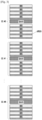
- a control signal having a form as shown in FIG. 3 may be transmitted on the downlink through each orthogonal frequency division multiplexing (OFDM) symbol of subframe #0 and subframe #25 in a radio frame composed of 50 subframes.
- OFDM orthogonal frequency division multiplexing
- FIG. 3 is a conceptual diagram simply showing the multiplexing on the frequency axis instead of actually showing all of subcarriers according to an embodiment of the present disclosure.
- a signal transmitted in the subframe may be formed by multiplexing, on the frequency axis, a synchronizing signal, a beam RS (BRS), and a physical broadcast channel (xPBCH) of the Pre-5G standard.
- the synchronizing signal and the BRS may be determined according to the value of a physical cell ID (PCID) of the corresponding cell.
- the xPBCH may be determined according to the PCID of the corresponding cell and a master information block (MIB) message. For example, if eight CCs have the same PCID value and if there is no difference in the MIB message for the respective CCs, the perfectly identical signal is repeated eight times on the frequency axis. Therefore, the PAPR may be increased by about 9 dB.
- a certain signal may be repeated on the frequency axis, thus causing an increase of PAPR.
- FIG. 4 is a diagram illustrating a signal transmitted at an OFDM symbol where a physical downlink control channel (xPDCCH) of the Pre-5G standard is transmitted.
- xPDCH physical downlink control channel
- the xPDCCH may be multiplexed on the frequency axis in one OFDM symbol together with a user equipment (UE)-specific RS associated with xPDCCH used for channel estimation in case of demodulating the xPDCCH signal.
- UE user equipment
- FIG. 4 is a conceptual diagram simply showing the multiplexing on the frequency axis instead of actually showing all of subcarriers.
- the xPDCCH transmission symbol has 16 resource element groups (xREGs) per CC, and each xREG may be composed of 48 resource elements (REs (tone)) used for xPDCCH transmission.
- the UE-specific RS associated with xPDCCH used for channel estimation in case of receiving the xPDCCH uses 24 REs per xREG and may be multiplexed with the 48 REs on the frequency axis.
- the xPDCCH may be randomized by control information to be transmitted to the terminal. However, the UE-specific RS associated with xPDCCH may repeatedly use the same sequence that depends on only the RS identification (RS ID) value in every xREG unit.
- RS ID RS identification
- the RS ID may use the PCID as a default value, and may use a setting value separately.
- the sequence of the UE-specific RS associated with xPDCCH may be repeated 16 times, and thereby the PAPR may be greatly increased. As the number of repetitions of the same signal on the frequency axis increases, the PAPR increase width may become greater.
- the transmitting apparatus can reduce the PAPR independently without agreement between the transmitting and receiving apparatuses.
- a method for further reducing the PAPR through agreement between the transmitting and receiving apparatuses will be described.
- FIG. 5 is a block diagrams illustrating elements of a transmitting apparatus 500 according to an example not belonging to the invention.
- the transmitting apparatus 500 can reduce the PAPR by controlling a phase in units of CC.
- the transmitting apparatus 500 may include a signal generator 511 for a first CC, a signal generator 512 for a second CC, and a signal generator 513 for an Nth CC.
- Each of the signal generators 511, 512 and 513 may generate a signal to be transmitted through each of the first to Nth CCs.
- each of the signal generators 511, 512 and 513 may generate a synchronizing signal, a RS for demodulation, etc. as well as data to be transmitted for each CC. At this time, each of the signal generators 511, 512 and 513 may generate different signals, depending on given cell information, a time index, and the like.
- the transmitting apparatus 500 may transform the signal generated for each CC into a time component signal through frequency/time conversion.
- the transmitting apparatus 500 may include a frequency/time transformer 521, a frequency/time transformer 522, and a frequency/time transformer 523.
- Each of the frequency/time transformers 521, 522 and 523 may transform the signal generated through each of the signal generators 511, 512 and 513 into a time component signal through frequency/time conversion.
- each of a phase rotator 531 for the first CC, a phase rotator 532 for the second CC, and a phase rotator 533 for the Nth CC may apply a predetermined phase to the time component signal of each CC.
- a phase rotation controller 540 of the transmitting apparatus 500 may determine a phase to be applied to each CC. Also, the phase rotation controller 540 may transmit information about the determined phase to the phase rotators 531, 532 and 533. Then, each of the phase rotators 531, 532 and 533 may rotate the time component signal by each phase value, based on the received phase information.
- the phase rotation controller 540 may determine e -j ⁇ /2 as a phase value to be applied to a signal for the first CC, e j0 as a phase value to be applied to a signal for the second CC, and e j ⁇ /2 as a phase value to be applied to a signal for the Nth CC. Also, the phase rotation controller 540 may transmit the determined phase values to the phase rotators 531, 532 and 533, respectively.
- the phase rotator 531 may multiply the time component signal for the first CC, obtained through the frequency/time transformer 521, by the determined phase value, e -j ⁇ /2 .
- the phase rotator 532 may multiply the time component signal for the second CC, obtained through the frequency/time transformer 522, by the determined phase value, e j0 .
- the phase rotator 533 may multiply the time component signal for the Nth CC, obtained through the frequency/time transformer 523, by the determined phase value, e j ⁇ /2 .
- the signal generators 511, 512 and 513 generate signals having the same sequence based on the same PCID, these signals are distinguished from each other by the multiplied different phase values.
- a DUC 550 may shift the center frequencies of the different time component signals. Then, the DUC 550 may transmit the signals to an RF unit such as a mixer.
- FIG. 6 is a block diagram illustrating elements of a transmitting apparatus 600 to which the first embodiment is applied so as to reduce the PAPR of signals repeated on the frequency axis within one CC according to an embodiment of the present disclosure.
- the transmitting apparatus 600 may include a signal generator 611 for a first REG, a signal generator 612 for a second REG, and a signal generator 613 for an Nth REG.
- Each of the signal generators 611, 612 and 613 may generate a signal to be transmitted at each of the first to Nth REGs.
- each of the signal generators 611, 612 and 613 may generate a synchronizing signal, a RS for demodulation, etc. as well as data to be transmitted for each REG. At this time, each of the signal generators 611, 612 and 613 may generate different signals, depending on given cell information, a time index, and the like.
- the transmitting apparatus 600 may apply a predetermined phase to each signal generated for each REG.
- each of a phase rotator 621 for the first REG, a phase rotator 622 for the second REG, and a phase rotator 623 for the Nth REG may apply a predetermined phase value to a frequency component signal of each REG.
- a phase rotation controller 630 of the transmitting apparatus 600 may determine a phase to be applied to each REG. Also, the phase rotation controller 630 may transmit information about the determined phase to the phase rotators 621, 622 and 623. Then, each of the phase rotators 621, 622 and 623 may rotate the frequency component signal generated for each REG by each phase value, based on the received phase information.
- the frequency component signal to which the phase value for each REG is applied may be mapped to a corresponding RE in the CC.
- a frequency mapper 641 may map the signal for the first REG, to which the phase value for the first REG is applied, to the RE corresponding to the first REG in the CC.
- a frequency mapper 642 may map the signal for the second REG, to which the phase value for the second REG is applied, to the RE corresponding to the second REG in the CC
- a frequency mapper 643 may map the signal for the Nth REG, to which the phase value for the Nth REG is applied, to the RE corresponding to the Nth REG in the CC.
- a frequency/time transformer 650 may be an inverse fast Fourier transform (IFFT) block.
- the frequency/time transformer 650 may transform the frequency component signal into a time component signal.
- IFFT inverse fast Fourier transform
- the time component signal may be shifted in a center frequency by a digital up converter, delivered to an RF unit such as a mixer, and transmitted to a receiving apparatus.
- the transmission apparatus can reduce the PAPR by applying a phase rotation in units of frequency blocks.
- the receiving apparatus can receive a signal intact through the typical receiving apparatus structure as described above with reference to FIG. 2 , regardless of the phase rotation.
- FIG. 7 is a flow diagram illustrating a signal transmission method of a transmitting apparatus according to an example not belonging to the invention.
- the transmitting apparatus may determine a phase for each predetermined frequency band unit.
- the predetermined frequency band unit may be a CC unit.
- the predetermined frequency band unit may be a REG unit in an arbitrary CC.
- the transmitting apparatus may apply the determined phase to a signal generated for each predetermined frequency band unit. Then, at operation S720, the transmitting apparatus may transmit the signal.
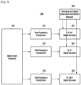
- FIG. 8 is a block diagram illustrating elements of a transmitting apparatus 800 according to the second example not belonging to the invention.
- the transmitting apparatus 800 is a device for simultaneously transmitting a plurality of CCs, and may include a transmitting-end signal generation information manager 810.
- the transmitting-end signal generation information manager 810 may create signal generation information for each arbitrary frequency unit and then transmit the created signal generation information to a signal generator for generating a signal for each arbitrary frequency unit.
- the arbitrary frequency unit may be a CC unit.
- the transmitting-end signal generation information manager 810 may create, as the signal generation information, different CC indexes depending on respective CCs.
- the transmitting apparatus 800 may transmit the signal generation information created by the transmitting-end signal generation information manager 810 to the receiving apparatus.
- the transmitting apparatus 800 may transmit the signal generation information to the receiving apparatus through a radio resource control (RRC) message. Therefore, the receiving apparatus described later may have the same signal generation information as the transmitting apparatus has.
- RRC radio resource control
- the transmitting apparatus 800 may include a signal generator 821 for a first CC, a signal generator 822 for a second CC, and a signal generator 823 for an Nth CC.
- Each of the signal generators 821, 822 and 823 may receive the signal generation information for each CC unit created by the transmitting-end signal generation information manager 810.
- each of the signal generators 821, 822 and 823 may generate a signal to be transmitted at each of the first to Nth CCs, based on the signal generation information.
- each of the signal generators 821, 822 and 823 may generate a synchronizing signal, a RS for demodulation, etc. as well as data to be transmitted for each CC.
- each of the signal generators 821, 822 and 823 may generate different signals, based on the signal generation information received from the transmitting-end signal generation information manager 810 as well as given cell information, a time index, and the like.
- the transmitting apparatus 800 may transform the signal generated for each CC into a time component signal through frequency/time conversion.
- the transmitting apparatus 800 may include a frequency/time transformer 831, a frequency/time transformer 832, and a frequency/time transformer 833.
- each of the frequency/time transformers 831, 832 and 833 may be an IFFT block.
- Each of the frequency/time transformers 831, 832 and 833 may transform the signal generated through each of the signal generators 821, 822 and 823 into a time component signal through frequency/time conversion.
- each of a phase rotator 841 for the first CC, a phase rotator 842 for the second CC, and a phase rotator 843 for the Nth CC may apply a predetermined phase to the time component signal of each CC.
- a phase rotation controller 850 of the transmitting apparatus 800 may determine a phase to be applied to each CC. Also, the phase rotation controller 850 may transmit information about the determined phase to the phase rotators 841, 842 and 843. Then, each of the phase rotators 841, 842 and 843 may rotate the time component signal by each phase value, based on the received phase information.
- the phase rotation controller 850 may determine e -j ⁇ /2 as a phase value to be applied to a signal for the first CC, e j0 as a phase value to be applied to a signal for the second CC, and e j ⁇ /2 as a phase value to be applied to a signal for the Nth CC. Also, the phase rotation controller 850 may transmit the determined phase values to the phase rotators 841, 842 and 843, respectively.
- the phase rotator 841 for the first CC may multiply the time component signal for the first CC, obtained through the frequency/time transformer 831, by the determined phase value, e -j ⁇ /2 .
- the phase rotator 842 for the second CC may multiply the time component signal for the second CC, obtained through the frequency/time transformer 832, by the determined phase value, e j0 .
- the phase rotator 843 for the Nth CC may multiply the time component signal for the Nth CC, obtained through the frequency/time transformer 833, by the determined phase value, e j ⁇ /2.
- the transmitting apparatus 800 may not perform the operations of the phase rotation controller 850 and the phase rotators 841, 842 and 843.
- the signal generators 821, 822 and 823 of the transmitting apparatus 800 may generate signals of different sequences, based on the created signal generation information. Therefore, the transmitting apparatus 800 may not perform the operations of applying different phase values for the respective CCs to rotation so as to generate signals of different sequences.
- a DUC 860 may shift the center frequencies of the different time component signals. Then, the DUC 860 may transmit the signals to an RF unit such as a mixer.
- FIG. 9 is a block diagram illustrating elements of a receiving apparatus 900 according to an example not belonging to the invention.
- the receiving apparatus 900 may receive signals from the transmitting apparatus 800. In addition, as described above, the receiving apparatus 900 may receive and store in advance the signal generation information created by the transmitting apparatus 800.
- the receiving apparatus 900 may separate a signal of each center frequency into signals for respective CCs through a DDC 910.
- the receiving apparatus 900 may transform the separated signal for each CC into a frequency component signal through time/frequency conversion.
- the receiving apparatus 900 may include a time/frequency transformer 921, a time/ frequency transformer 922, and a time/frequency transformer 923.
- Each of the time/ frequency transformers 921, 922 and 923 may be a fast Fourier transform (FFT) block.
- FFT fast Fourier transform
- Each of the time/frequency transformers 921, 922 and 923 may transform the signal separated for each CC into a frequency component signal through time/frequency conversion.
- the receiving apparatus 900 may perform the reception of a signal for each CC.
- the receiving apparatus 900 may include a signal receiver 931 for a first CC, a signal receiver 932 for a second CC, and a signal receiver 933 for an Nth CC.
- the signal receivers 931, 932 and 933 may recognize the operations of the signal generators 821, 822 and 823 of the transmitting apparatus 800 and then obtain synchronization by estimating a synchronizing signal. In addition, the signal receivers 931, 932 and 933 may estimate a RS for demodulation and use it for channel estimation. Also, the signal receivers 931, 932 and 933 may demodulate a data channel, based on the obtained information.
- each of the signal receivers 931, 932 and 933 may accurately predict the transmitted signal by using the signal generation information transmitted from the transmitting apparatus 800.
- a receiving-end signal generation information manager 940 may receive and store the signal generation information created by the transmitting apparatus 800. In addition, the receiving-end signal generation information manager 940 may deliver the corresponding signal generation information for each CC to each of the signal receivers 931, 932 and 933.
- the transmitting-end signal generation information manager 810 and the receiving-end signal generation information manager 940 should have the same value through prearranged agreement about the signal generation information for each CC in order to prevent a problem in signal reception.
- the transmitting apparatus 800 may transmit in advance the signal generation information for each CC to the receiving apparatus 900.
- the transmitting apparatus 800 may be a base station, and the receiving apparatus 900 may be a user terminal.
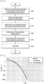
- FIG. 10 is a flow diagram illustrating a signal transmission method of a transmitting apparatus according to an example not belonging to the invention.
- the transmitting apparatus may determine signal generation information for generating signals of different sequences by each predetermined frequency band unit.
- the predetermined frequency band unit may be a CC unit.
- the predetermined frequency band unit may be a REG unit in an arbitrary CC.
- the signal generation information may be different CC indexes depending on respective CCs.
- the transmitting apparatus may transmit created signal generation information to the receiving apparatus.
- the transmitting apparatus may transmit the signal generation information to the receiving apparatus through a RRC message.
- the transmitting apparatus may generate a signal for each predetermined frequency band unit, based on the signal generation information. For example, the transmitting apparatus may generate signals of different sequences, based on the signal generation information as well as given cell information, a time index, and the like.
- the transmitting apparatus may determine a phase for each predetermined frequency band unit. Also, at operation S1040, the transmitting apparatus may apply the determined phase to a signal generated for each predetermined frequency band unit. Then, at operation S1050, the transmitting apparatus may transmit the signal.
- the receiving apparatus may receive the signal generation information for generating signals of different sequences by each predetermined frequency band unit.
- the receiving apparatus may decode the received signal, based on the signal generation information.
- FIG. 11 is a diagram illustrating a PAPR reduction effect according to the present disclosure.
- FIG. 11 shows that the effect of reducing the PAPR can be obtained when the transmitting apparatus generates and transmits a signal according to the present disclosure.
- the PAPR can be reduced in the wireless communication system that uses a plurality of frequency resources simultaneously.
- the transmitting apparatus can improve the throughput and coverage by transmitting signals with higher average power.
- the elements of the above-described apparatuses may be implemented in software.
- the signal generation information managers of the transmitting apparatus and the receiving apparatus or the phase rotation controller of the transmitting apparatus may further include a flash memory or any other nonvolatile memory.
- a program for performing the operations of the signal generation information manager or the phase rotation controller may be stored.
- the signal generation information managers of the transmitting apparatus and the receiving apparatus or the phase rotation controller of the transmitting apparatus may be implemented in the form of including a CPU and a random access memory (RAM).
- the CPU may perform the above-discussed operations by copying programs stored in the nonvolatile memory to the RAM and then executing the copied programs.
- the above manager or controller may be used in the same meaning as a CPU, a microprocessor, a control unit, a processor, and an operating system. Also, the manager or controller may be implemented as a single-chip system (also referred to as a system-on-a-chip, a system on chip (SOC), or SoC) together with other functional units such as a communication module.
- a single-chip system also referred to as a system-on-a-chip, a system on chip (SOC), or SoC
- SOC system on chip
- the signal transmission method of the transmitting apparatus may be software-coded and stored in a non-transitory readable medium.
- This non-transitory readable medium may be mounted and used in various devices.
- the non-transitory readable medium means a medium that is readable by a device and stores data semipermanently rather than a medium that stores data for a short period of time, such as a register, cache, memory, etc.
- the non-transitory readable medium may be a compact disc (CD), a digital versatile disc (DVD), a hard disk, a Blu-ray disk, a universal serial bus (USB), a memory card, a read-only memory (ROM), or the like.
Landscapes
- Engineering & Computer Science (AREA)
- Signal Processing (AREA)
- Computer Networks & Wireless Communication (AREA)
- Mobile Radio Communication Systems (AREA)
Claims (6)
- Procédé de transmission de signal d'un dispositif de transmission (600) dans un système de communication sans fil, le procédé comprenant :déterminer une pluralité de phases pour une pluralité de groupes d'éléments de ressources, REGs, dans une porteuse à composants arbitraires, CC, afin de réduire le rapport puissance de crête/puissance moyenne, PAPR, des signaux ;appliquer la pluralité de phases déterminée aux signaux pour la pluralité de REGs ; ettransmettre les signaux, auxquels la pluralité de phases déterminée est appliquée, simultanément, en se basant sur la pluralité de REGs,dans lequel chacune de la pluralité de phases déterminée est appliquée à un signal d'un REG correspondant parmi la pluralité de REGs.
- Procédé de la revendication 1,dans lequel une même séquence est utilisée pour générer les signaux pour la pluralité de REGs,dans lequel la pluralité de REGs augmente le rapport puissance de crête/puissance moyenne, PAPR, des signaux au-delà d'un seuil, etdans lequel la pluralité de phases est déterminée pour réduire le PAPR des signaux.
- Procédé de la revendication 1, comprenant en outre :déterminer les informations de génération de signaux afin de générer un signal de domaine temporel pour la pluralité de REGs en se basant sur les signaux ;générer le signal de domaine temporel pour la pluralité de REGs, en se basant sur les informations de génération de signal ; ettransmettre les informations de génération de signal à un dispositif récepteur avant de transmettre le signal de domaine temporel généré au dispositif récepteur, etdans lequel les informations de génération de signal sont transmises au dispositif récepteur par le biais d'un message de commande de ressources radio, RRC.
- Dispositif de transmission (600) dans un système de communication sans fil, le dispositif de transmission (600) comprenant :un émetteur-récepteur configuré pour transmettre et pour recevoir un signal ; etune commande configurée pour :déterminer une pluralité de phases pour une pluralité de groupes d'éléments de ressources, REGs, dans une porteuse à composants arbitraires, CC, afin de réduire le rapport puissance de crête/puissance moyenne, PAPR, des signaux,appliquer la pluralité de phases déterminée aux signaux pour la pluralité de REGs, etcommander l'émetteur-récepteur pour qu'il transmette les signaux, auxquels la pluralité de phases déterminée est appliquée, simultanément, en se basant sur la pluralité de REGs,dans lequel chacune de la pluralité de phases déterminée est appliquée à un signal d'une unité de bande de fréquence correspondante parmi la pluralité de REGs.
- Dispositif de transmission (600) de la revendication 4,dans lequel une même séquence est utilisée pour générer les signaux pour la pluralité de REGs,dans lequel la pluralité de REGs augmente le rapport puissance de crête/puissance moyenne, PAPR, des signaux au-delà d'un seuil, etdans lequel la pluralité de phases est déterminée pour réduire le PAPR des signaux.
- Dispositif de transmission (600) de la revendication 4, dans lequel la commande est en outre configurée pour :déterminer les informations de génération de signaux afin de générer un signal de domaine temporel pour la pluralité de REGs en se basant sur les signaux,générer le signal de domaine temporel pour la pluralité de REGs, en se basant sur les informations de génération de signal, ettransmettre les informations de génération de signal à un dispositif récepteur avant de transmettre le signal de domaine temporel généré au dispositif récepteur, etdans lequel les informations de génération de signal sont transmises au dispositif récepteur par le biais d'un message de commande de ressources radio, RRC.
Applications Claiming Priority (3)
| Application Number | Priority Date | Filing Date | Title |
|---|---|---|---|
| US201662425418P | 2016-11-22 | 2016-11-22 | |
| KR1020160166196A KR102640609B1 (ko) | 2016-11-22 | 2016-12-07 | 무선 통신 시스템에 있어서, 송수신 장치 및 이의 신호 송수신 방법 |
| PCT/KR2017/013332 WO2018097591A1 (fr) | 2016-11-22 | 2017-11-22 | Appareil et procédé pour émettre et recevoir des signaux dans un système de communication sans fil |
Publications (3)
| Publication Number | Publication Date |
|---|---|
| EP3510740A1 EP3510740A1 (fr) | 2019-07-17 |
| EP3510740A4 EP3510740A4 (fr) | 2019-10-16 |
| EP3510740B1 true EP3510740B1 (fr) | 2025-01-08 |
Family
ID=62300361
Family Applications (1)
| Application Number | Title | Priority Date | Filing Date |
|---|---|---|---|
| EP17873507.2A Active EP3510740B1 (fr) | 2016-11-22 | 2017-11-22 | Appareil et procédé pour émettre et recevoir des signaux dans un système de communication sans fil |
Country Status (2)
| Country | Link |
|---|---|
| EP (1) | EP3510740B1 (fr) |
| KR (1) | KR102640609B1 (fr) |
Families Citing this family (1)
| Publication number | Priority date | Publication date | Assignee | Title |
|---|---|---|---|---|
| US12363775B2 (en) * | 2021-09-23 | 2025-07-15 | Apple Inc. | Multi-device synchronization and data transmission |
Citations (1)
| Publication number | Priority date | Publication date | Assignee | Title |
|---|---|---|---|---|
| WO2010042885A1 (fr) * | 2008-10-10 | 2010-04-15 | Powerwave Technologies, Inc. | Réduction du facteur de crête pour des systèmes de communication ofdm par la transmission de blocs de ressources déphasés |
Family Cites Families (2)
| Publication number | Priority date | Publication date | Assignee | Title |
|---|---|---|---|---|
| WO2010116881A1 (fr) * | 2009-04-10 | 2010-10-14 | 日本電気株式会社 | Système de communication sans fil, station de base, serveur, procédé de communication sans fil et programme |
| EP2448334A4 (fr) * | 2009-06-22 | 2016-12-21 | Alcatel Lucent | Procédé et dispositif pour l'exécution d'une pluralité de composantes porteuses qui sont agrégées pour la transmission |
-
2016
- 2016-12-07 KR KR1020160166196A patent/KR102640609B1/ko active Active
-
2017
- 2017-11-22 EP EP17873507.2A patent/EP3510740B1/fr active Active
Patent Citations (1)
| Publication number | Priority date | Publication date | Assignee | Title |
|---|---|---|---|---|
| WO2010042885A1 (fr) * | 2008-10-10 | 2010-04-15 | Powerwave Technologies, Inc. | Réduction du facteur de crête pour des systèmes de communication ofdm par la transmission de blocs de ressources déphasés |
Non-Patent Citations (1)
| Title |
|---|
| SEON-AE KIM ET AL: "Design and Analysis of Side Information Embedded PTS Scheme in the OFDM Communication System", 1 January 2006, WIRELESS ALGORITHMS, SYSTEMS, AND APPLICATIONS LECTURE NOTES IN COMPUTER SCIENCE;;LNCS, SPRINGER, BERLIN, DE, PAGE(S) 550 - 560, ISBN: 978-3-540-37189-2, XP019041931 * |
Also Published As
| Publication number | Publication date |
|---|---|
| EP3510740A4 (fr) | 2019-10-16 |
| KR102640609B1 (ko) | 2024-02-26 |
| KR20180057460A (ko) | 2018-05-30 |
| EP3510740A1 (fr) | 2019-07-17 |
Similar Documents
| Publication | Publication Date | Title |
|---|---|---|
| CN110603757B (zh) | 下一代蜂窝网络中初始接入的方法和装置 | |
| EP3497860B1 (fr) | Concept de signal de référence de démodulation (dm-rs) pour communication de véhicule à véhicule | |
| EP4451600B1 (fr) | Systèmes et procédés pour système à structures multiphysiques | |
| TWI717440B (zh) | 通訊裝置及通訊方法 | |
| US10651982B2 (en) | User terminal, radio base station, and radio communication method | |
| CN111357379A (zh) | 用于早期数据传输的物理层增强 | |
| WO2019029240A1 (fr) | Procédé et dispositif de brouillage et de désembrouillage de signal | |
| KR20250003653A (ko) | 무선 통신 시스템에서 서브밴드를 설정하는 방법 및 이를 위한 장치 | |
| CN115053497A (zh) | 用于无线通信系统中传输上行链路信道的方法和设备 | |
| CN112313892B (zh) | 用于在无线通信系统中发送和接收调制信号的方法和设备 | |
| EP4120645A1 (fr) | Procédé et dispositif basés sur un ofdm et permettant d'étaler et de transmettre des données compressées | |
| CN103546259B (zh) | 传输信号的发送、接收方法及终端、基站 | |
| JP2024117082A (ja) | 新無線のコアセット#0の割り当て | |
| CN102420644B (zh) | 一种基于用户专属参考信号的发送方法、接收方法和设备 | |
| CN116095839A (zh) | 一种信号组的发送/接收方法及其装置 | |
| US10693696B2 (en) | Apparatus and method for transmitting and receiving signals in wireless communication system | |
| CN118805353A (zh) | 经由信道资源集的上行链路控制信息的传输 | |
| WO2017073084A1 (fr) | Systèmes et procédés pour un système à plusieurs structures physiques | |
| EP3510740B1 (fr) | Appareil et procédé pour émettre et recevoir des signaux dans un système de communication sans fil | |
| CN117880974A (zh) | 传输信号的频谱扩展 | |
| WO2017073085A1 (fr) | Systèmes et procédés pour système de structure multi-physique | |
| WO2023287537A1 (fr) | Vérification de clé secrète dans une communication sans fil | |
| KR20220049222A (ko) | 무선통신 시스템에서 상향 링크 채널 송신 방법 및 장치 |
Legal Events
| Date | Code | Title | Description |
|---|---|---|---|
| STAA | Information on the status of an ep patent application or granted ep patent |
Free format text: STATUS: THE INTERNATIONAL PUBLICATION HAS BEEN MADE |
|
| PUAI | Public reference made under article 153(3) epc to a published international application that has entered the european phase |
Free format text: ORIGINAL CODE: 0009012 |
|
| STAA | Information on the status of an ep patent application or granted ep patent |
Free format text: STATUS: REQUEST FOR EXAMINATION WAS MADE |
|
| 17P | Request for examination filed |
Effective date: 20190412 |
|
| AK | Designated contracting states |
Kind code of ref document: A1 Designated state(s): AL AT BE BG CH CY CZ DE DK EE ES FI FR GB GR HR HU IE IS IT LI LT LU LV MC MK MT NL NO PL PT RO RS SE SI SK SM TR |
|
| AX | Request for extension of the european patent |
Extension state: BA ME |
|
| RIC1 | Information provided on ipc code assigned before grant |
Ipc: H04L 5/00 20060101ALI20190828BHEP Ipc: H04L 27/34 20060101AFI20190828BHEP Ipc: H04L 27/26 20060101ALI20190828BHEP Ipc: H04L 1/00 20060101ALI20190828BHEP |
|
| A4 | Supplementary search report drawn up and despatched |
Effective date: 20190913 |
|
| RIC1 | Information provided on ipc code assigned before grant |
Ipc: H04L 27/26 20060101ALI20190906BHEP Ipc: H04L 5/00 20060101ALI20190906BHEP Ipc: H04L 1/00 20060101ALI20190906BHEP Ipc: H04L 27/34 20060101AFI20190906BHEP |
|
| DAV | Request for validation of the european patent (deleted) | ||
| DAX | Request for extension of the european patent (deleted) | ||
| STAA | Information on the status of an ep patent application or granted ep patent |
Free format text: STATUS: EXAMINATION IS IN PROGRESS |
|
| 17Q | First examination report despatched |
Effective date: 20200721 |
|
| GRAP | Despatch of communication of intention to grant a patent |
Free format text: ORIGINAL CODE: EPIDOSNIGR1 |
|
| STAA | Information on the status of an ep patent application or granted ep patent |
Free format text: STATUS: GRANT OF PATENT IS INTENDED |
|
| INTG | Intention to grant announced |
Effective date: 20240905 |
|
| GRAS | Grant fee paid |
Free format text: ORIGINAL CODE: EPIDOSNIGR3 |
|
| GRAA | (expected) grant |
Free format text: ORIGINAL CODE: 0009210 |
|
| STAA | Information on the status of an ep patent application or granted ep patent |
Free format text: STATUS: THE PATENT HAS BEEN GRANTED |
|
| AK | Designated contracting states |
Kind code of ref document: B1 Designated state(s): AL AT BE BG CH CY CZ DE DK EE ES FI FR GB GR HR HU IE IS IT LI LT LU LV MC MK MT NL NO PL PT RO RS SE SI SK SM TR |
|
| REG | Reference to a national code |
Ref country code: GB Ref legal event code: FG4D |
|
| REG | Reference to a national code |
Ref country code: CH Ref legal event code: EP |
|
| REG | Reference to a national code |
Ref country code: DE Ref legal event code: R096 Ref document number: 602017087288 Country of ref document: DE |
|
| REG | Reference to a national code |
Ref country code: IE Ref legal event code: FG4D |
|
| REG | Reference to a national code |
Ref country code: LT Ref legal event code: MG9D |
|
| REG | Reference to a national code |
Ref country code: NL Ref legal event code: MP Effective date: 20250108 |
|
| REG | Reference to a national code |
Ref country code: AT Ref legal event code: MK05 Ref document number: 1759046 Country of ref document: AT Kind code of ref document: T Effective date: 20250108 |
|
| PG25 | Lapsed in a contracting state [announced via postgrant information from national office to epo] |
Ref country code: NL Free format text: LAPSE BECAUSE OF FAILURE TO SUBMIT A TRANSLATION OF THE DESCRIPTION OR TO PAY THE FEE WITHIN THE PRESCRIBED TIME-LIMIT Effective date: 20250108 |
|
| PG25 | Lapsed in a contracting state [announced via postgrant information from national office to epo] |
Ref country code: RS Free format text: LAPSE BECAUSE OF FAILURE TO SUBMIT A TRANSLATION OF THE DESCRIPTION OR TO PAY THE FEE WITHIN THE PRESCRIBED TIME-LIMIT Effective date: 20250408 |
|
| PG25 | Lapsed in a contracting state [announced via postgrant information from national office to epo] |
Ref country code: FI Free format text: LAPSE BECAUSE OF FAILURE TO SUBMIT A TRANSLATION OF THE DESCRIPTION OR TO PAY THE FEE WITHIN THE PRESCRIBED TIME-LIMIT Effective date: 20250108 |
|
| PG25 | Lapsed in a contracting state [announced via postgrant information from national office to epo] |
Ref country code: PL Free format text: LAPSE BECAUSE OF FAILURE TO SUBMIT A TRANSLATION OF THE DESCRIPTION OR TO PAY THE FEE WITHIN THE PRESCRIBED TIME-LIMIT Effective date: 20250108 |
|
| PG25 | Lapsed in a contracting state [announced via postgrant information from national office to epo] |
Ref country code: ES Free format text: LAPSE BECAUSE OF FAILURE TO SUBMIT A TRANSLATION OF THE DESCRIPTION OR TO PAY THE FEE WITHIN THE PRESCRIBED TIME-LIMIT Effective date: 20250108 |
|
| PG25 | Lapsed in a contracting state [announced via postgrant information from national office to epo] |
Ref country code: IS Free format text: LAPSE BECAUSE OF FAILURE TO SUBMIT A TRANSLATION OF THE DESCRIPTION OR TO PAY THE FEE WITHIN THE PRESCRIBED TIME-LIMIT Effective date: 20250508 Ref country code: NO Free format text: LAPSE BECAUSE OF FAILURE TO SUBMIT A TRANSLATION OF THE DESCRIPTION OR TO PAY THE FEE WITHIN THE PRESCRIBED TIME-LIMIT Effective date: 20250408 |
|
| PG25 | Lapsed in a contracting state [announced via postgrant information from national office to epo] |
Ref country code: HR Free format text: LAPSE BECAUSE OF FAILURE TO SUBMIT A TRANSLATION OF THE DESCRIPTION OR TO PAY THE FEE WITHIN THE PRESCRIBED TIME-LIMIT Effective date: 20250108 |
|
| PG25 | Lapsed in a contracting state [announced via postgrant information from national office to epo] |
Ref country code: PT Free format text: LAPSE BECAUSE OF FAILURE TO SUBMIT A TRANSLATION OF THE DESCRIPTION OR TO PAY THE FEE WITHIN THE PRESCRIBED TIME-LIMIT Effective date: 20250508 Ref country code: LV Free format text: LAPSE BECAUSE OF FAILURE TO SUBMIT A TRANSLATION OF THE DESCRIPTION OR TO PAY THE FEE WITHIN THE PRESCRIBED TIME-LIMIT Effective date: 20250108 |
|
| PG25 | Lapsed in a contracting state [announced via postgrant information from national office to epo] |
Ref country code: GR Free format text: LAPSE BECAUSE OF FAILURE TO SUBMIT A TRANSLATION OF THE DESCRIPTION OR TO PAY THE FEE WITHIN THE PRESCRIBED TIME-LIMIT Effective date: 20250409 Ref country code: BG Free format text: LAPSE BECAUSE OF FAILURE TO SUBMIT A TRANSLATION OF THE DESCRIPTION OR TO PAY THE FEE WITHIN THE PRESCRIBED TIME-LIMIT Effective date: 20250108 |
|
| PG25 | Lapsed in a contracting state [announced via postgrant information from national office to epo] |
Ref country code: AT Free format text: LAPSE BECAUSE OF FAILURE TO SUBMIT A TRANSLATION OF THE DESCRIPTION OR TO PAY THE FEE WITHIN THE PRESCRIBED TIME-LIMIT Effective date: 20250108 |
|
| PG25 | Lapsed in a contracting state [announced via postgrant information from national office to epo] |
Ref country code: SE Free format text: LAPSE BECAUSE OF FAILURE TO SUBMIT A TRANSLATION OF THE DESCRIPTION OR TO PAY THE FEE WITHIN THE PRESCRIBED TIME-LIMIT Effective date: 20250108 |
|
| PG25 | Lapsed in a contracting state [announced via postgrant information from national office to epo] |
Ref country code: SM Free format text: LAPSE BECAUSE OF FAILURE TO SUBMIT A TRANSLATION OF THE DESCRIPTION OR TO PAY THE FEE WITHIN THE PRESCRIBED TIME-LIMIT Effective date: 20250108 |
|
| REG | Reference to a national code |
Ref country code: DE Ref legal event code: R097 Ref document number: 602017087288 Country of ref document: DE |
|
| PG25 | Lapsed in a contracting state [announced via postgrant information from national office to epo] |
Ref country code: DK Free format text: LAPSE BECAUSE OF FAILURE TO SUBMIT A TRANSLATION OF THE DESCRIPTION OR TO PAY THE FEE WITHIN THE PRESCRIBED TIME-LIMIT Effective date: 20250108 |
|
| PG25 | Lapsed in a contracting state [announced via postgrant information from national office to epo] |
Ref country code: CZ Free format text: LAPSE BECAUSE OF FAILURE TO SUBMIT A TRANSLATION OF THE DESCRIPTION OR TO PAY THE FEE WITHIN THE PRESCRIBED TIME-LIMIT Effective date: 20250108 Ref country code: EE Free format text: LAPSE BECAUSE OF FAILURE TO SUBMIT A TRANSLATION OF THE DESCRIPTION OR TO PAY THE FEE WITHIN THE PRESCRIBED TIME-LIMIT Effective date: 20250108 |
|
| PG25 | Lapsed in a contracting state [announced via postgrant information from national office to epo] |
Ref country code: RO Free format text: LAPSE BECAUSE OF FAILURE TO SUBMIT A TRANSLATION OF THE DESCRIPTION OR TO PAY THE FEE WITHIN THE PRESCRIBED TIME-LIMIT Effective date: 20250108 |
|
| PG25 | Lapsed in a contracting state [announced via postgrant information from national office to epo] |
Ref country code: SK Free format text: LAPSE BECAUSE OF FAILURE TO SUBMIT A TRANSLATION OF THE DESCRIPTION OR TO PAY THE FEE WITHIN THE PRESCRIBED TIME-LIMIT Effective date: 20250108 |
|
| PLBE | No opposition filed within time limit |
Free format text: ORIGINAL CODE: 0009261 |
|
| STAA | Information on the status of an ep patent application or granted ep patent |
Free format text: STATUS: NO OPPOSITION FILED WITHIN TIME LIMIT |
|
| 26N | No opposition filed |
Effective date: 20251009 |
|
| PGFP | Annual fee paid to national office [announced via postgrant information from national office to epo] |
Ref country code: DE Payment date: 20251020 Year of fee payment: 9 |
|
| PGFP | Annual fee paid to national office [announced via postgrant information from national office to epo] |
Ref country code: GB Payment date: 20251023 Year of fee payment: 9 |
|
| PG25 | Lapsed in a contracting state [announced via postgrant information from national office to epo] |
Ref country code: IT Free format text: LAPSE BECAUSE OF FAILURE TO SUBMIT A TRANSLATION OF THE DESCRIPTION OR TO PAY THE FEE WITHIN THE PRESCRIBED TIME-LIMIT Effective date: 20250108 |