EP3510848B1 - Kühlsysteme für in reihe angeordnete vorrichtungen - Google Patents
Kühlsysteme für in reihe angeordnete vorrichtungen Download PDFInfo
- Publication number
- EP3510848B1 EP3510848B1 EP17765057.9A EP17765057A EP3510848B1 EP 3510848 B1 EP3510848 B1 EP 3510848B1 EP 17765057 A EP17765057 A EP 17765057A EP 3510848 B1 EP3510848 B1 EP 3510848B1
- Authority
- EP
- European Patent Office
- Prior art keywords
- air
- air duct
- rows
- cooling system
- aisle
- Prior art date
- Legal status (The legal status is an assumption and is not a legal conclusion. Google has not performed a legal analysis and makes no representation as to the accuracy of the status listed.)
- Active
Links
Images


Classifications
-
- H—ELECTRICITY
- H05—ELECTRIC TECHNIQUES NOT OTHERWISE PROVIDED FOR
- H05K—PRINTED CIRCUITS; CASINGS OR CONSTRUCTIONAL DETAILS OF ELECTRIC APPARATUS; MANUFACTURE OF ASSEMBLAGES OF ELECTRICAL COMPONENTS
- H05K7/00—Constructional details common to different types of electric apparatus
- H05K7/20—Modifications to facilitate cooling, ventilating, or heating
- H05K7/20709—Modifications to facilitate cooling, ventilating, or heating for server racks or cabinets; for data centers, e.g. 19-inch computer racks
- H05K7/20718—Forced ventilation of a gaseous coolant
- H05K7/20745—Forced ventilation of a gaseous coolant within rooms for removing heat from cabinets, e.g. by air conditioning device
-
- H—ELECTRICITY
- H05—ELECTRIC TECHNIQUES NOT OTHERWISE PROVIDED FOR
- H05K—PRINTED CIRCUITS; CASINGS OR CONSTRUCTIONAL DETAILS OF ELECTRIC APPARATUS; MANUFACTURE OF ASSEMBLAGES OF ELECTRICAL COMPONENTS
- H05K7/00—Constructional details common to different types of electric apparatus
- H05K7/20—Modifications to facilitate cooling, ventilating, or heating
- H05K7/20009—Modifications to facilitate cooling, ventilating, or heating using a gaseous coolant in electronic enclosures
- H05K7/20127—Natural convection
-
- H—ELECTRICITY
- H05—ELECTRIC TECHNIQUES NOT OTHERWISE PROVIDED FOR
- H05K—PRINTED CIRCUITS; CASINGS OR CONSTRUCTIONAL DETAILS OF ELECTRIC APPARATUS; MANUFACTURE OF ASSEMBLAGES OF ELECTRICAL COMPONENTS
- H05K7/00—Constructional details common to different types of electric apparatus
- H05K7/20—Modifications to facilitate cooling, ventilating, or heating
- H05K7/20009—Modifications to facilitate cooling, ventilating, or heating using a gaseous coolant in electronic enclosures
- H05K7/20136—Forced ventilation, e.g. by fans
- H05K7/20145—Means for directing air flow, e.g. ducts, deflectors, plenum or guides
-
- H—ELECTRICITY
- H05—ELECTRIC TECHNIQUES NOT OTHERWISE PROVIDED FOR
- H05K—PRINTED CIRCUITS; CASINGS OR CONSTRUCTIONAL DETAILS OF ELECTRIC APPARATUS; MANUFACTURE OF ASSEMBLAGES OF ELECTRICAL COMPONENTS
- H05K7/00—Constructional details common to different types of electric apparatus
- H05K7/20—Modifications to facilitate cooling, ventilating, or heating
- H05K7/20009—Modifications to facilitate cooling, ventilating, or heating using a gaseous coolant in electronic enclosures
- H05K7/20136—Forced ventilation, e.g. by fans
- H05K7/20172—Fan mounting or fan specifications
-
- H—ELECTRICITY
- H05—ELECTRIC TECHNIQUES NOT OTHERWISE PROVIDED FOR
- H05K—PRINTED CIRCUITS; CASINGS OR CONSTRUCTIONAL DETAILS OF ELECTRIC APPARATUS; MANUFACTURE OF ASSEMBLAGES OF ELECTRICAL COMPONENTS
- H05K7/00—Constructional details common to different types of electric apparatus
- H05K7/20—Modifications to facilitate cooling, ventilating, or heating
- H05K7/20536—Modifications to facilitate cooling, ventilating, or heating for racks or cabinets of standardised dimensions, e.g. electronic racks for aircraft or telecommunication equipment
- H05K7/20554—Forced ventilation of a gaseous coolant
Definitions
- This patent generally pertains to cooling systems and more specifically to cooling systems for devices arranged in rows.
- Server-based datacenters are a large collection of computers, often at a physically remote but network accessible location, that provide clients with expanded computing capability.
- the expanded computing capability typically is in the form of data storage, data processing, database management, file management, and website management.
- Each computer of the system usually includes a base or case supporting a set of computer components.
- computer components may include items such as one or more microprocessors, hard drives, solid state memory devices, routers and power supplies. More generally, there are many types of electronic equipment and/or other devices that may emit heat to the surrounding area during operation.
- the base or case of each computer or other heat generating device usually includes or is otherwise associated with a cooling fan that forces a current of environmentally controlled air from a front face of the computer or other device, across the components, and out through a back end of the computer or other device. In some cases, it is this current of air that defines the front and back ends of the computer or other device.
- computers at a datacenter may be stacked in rack-like cabinets that are neatly arranged in rows separated by aisles.
- the aisles provide manual access to the front and back ends of the computers.
- the rows of computers are oriented such that each individual aisle is exposed solely to computer fronts or solely to computer backs.
- the front ends of computers in one row face the front ends of computers in the next row across the aisle.
- the back ends of computers on opposite sides of that aisle face each other.
- Aisles of computer fronts are generally cooler than backside aisles due to the computer components heating the current of air developed by the computers' internal cooling fans.
- front side cooler aisles are often called “cold aisles,” and back side aisles are known as “hot aisles.”
- Cold aisles front side cooler aisles
- hot aisles back side aisles
- Each aisle being exposed to only computer fronts or to only computer backs creates an alternating arrangement of cold aisles and hot aisles.
- Similar arrangements of other types of electronic equipment or other devices that generate heat may be implemented to cool such devices during operation.
- a building air conditioning system is usually needed to prevent the computers from overheating.
- a generally inert gas system or some other type of fire suppression system automatically activates to prevent or reduce (e.g., minimize) damage.
- US 2016/029513 A1 discloses a cooling system with a mobile soft duct arrangement which includes a soft duct that can be extended and retracted along a track to deliver an air supply to various locations.
- a vent attached to a part of the soft duct system can include a flow control element that can be adjusted to direct air to a target location.
- Managing a soft duct system can include monitoring an environment to detect temperature hotspots and configuring the soft duct system, in response to detection of a hotspot at a particular location, to deliver air to the particular location to mitigate the hotspot.
- Configuring the soft duct system can include extending the soft duct along the track and adjusting a flow control element in a vent to direct air to the particular location.
- Soft duct system management can be implemented by one or more computer systems.
- An example system includes a tubular duct comprising a pliable wall dividing an interior of the tubular duct from an exterior of the tubular duct.
- the system includes an outlet member to be attached to the pliable wall.
- the outlet member defines a main air passageway with a first flow resistance therethrough and places the interior of the tubular duct in fluid communication with the exterior of the tubular duct.
- the system includes a secondary air passageway with a second flow resistance therethrough.
- the secondary air passageway is defined by at least one of the outlet member or the pliable wall and extends from the interior of the tubular duct to the exterior of the tubular duct to define an airflow path proximate the outlet member.
- the second flow resistance is significantly greater than the first flow resistance.
- WO 2010/095931 A1 relates to a method for cooling an ICT room, which ICT room contains at least one row of continuous racks having ICT equipment that needs to be cooled.
- a fabric air duct of an HVAC system (heating, ventilating and air conditioning system) includes a discharge air register with an air deflector that extends along the length of the duct. Rotating or twisting the deflector adjusts the volume and/or direction of the air being discharged from the register.
- US 2006/252365 A1 discloses an air-handling system including an inflatable air duct with a discharge member whose discharge opening varies with the static pressure or flow rate within the duct.
- the discharge opening in some embodiments, tends to close in response to reduced air pressure associated with the lower airflow. The closing of the discharge opening prevents the static pressure from decreasing as much as the pressure would otherwise if the discharge opening were fixed.
- the present invention provides a cooling system according to the subject-matter of independent claim 1.
- Example cooling systems for server-based datacenters, or server farms include air permeable inflatable air ducts installed above multiple rows of computer racks.
- the air ducts in the event of a fire, deflate and collapse so as not to obstruct the flow of a fire extinguishing gas.
- the air ducts when inflated, have an expanded shape that inhibits adverse mixing of air between hot aisles and cold aisles.
- wings extend laterally from the air duct to further reduce the mixing of hot and cold air.
- a series of inflatable branch ducts extend downward from a supply air duct to reach well into cold aisles.
- nozzles and/or internal baffles promote radial air discharge from the supply air duct.
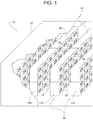
- FIGS. 1 and 2 show an example datacenter 10 including a building 12 containing a plurality of computers 14 in a plurality of cabinets 16.
- the term, "computer” refers to any digital processing device, examples of which include a server, a data storage device, a hard drive, a solid state memory, etc.
- the term, "cabinet” refers to any structure for supporting and/or housing one or more of the plurality of computers 14. Examples of a cabinet include a plurality of enclosures supporting and/or housing at least one computer, a single enclosure containing a single computer, a single enclosure housing a plurality of computers, a rack, a shelf, etc.
- the term, "row of computers” encompasses the associated cabinets (i.e., the racks, shelving, and/or other enclosure or support for the computers). So, in some examples, the terms, “row of computers” and “row of cabinets” can be used interchangeably.
- the teachings of this disclosure are described with respect to rows of computers, the teachings of this disclosure may apply to any other type of electronic equipment or devices that are to be cooled through forced air when arranged in one or more rows.
- the cabinets 16 are arranged in a plurality of rows 18 to create a first row of computers 18a (a first row of cabinets) and a second row of computers 18b (a second row of cabinets).
- the plurality of rows of computers 18 also creates an alternating arrangement of a plurality of cold aisles 20 (e.g., a first aisle 20a) and a plurality of hot aisles 22 (e.g., a second aisle 22a and a third aisle 22b).
- the term "aisle” refers to the space between adjacent rows of computers 18 as well as the space adjacent the outer side of an outer row of the plurality of rows 18.
- At least one computer 14 and/or at least one row of cabinets 16 define an air passageway 24 between a cold aisle 20a and one or more hot aisles 22a, 22b.
- One or more internal fans 25 within the air passageway 24 creates a current of air 26 (e.g., a first current of air 26a from the cold aisle 20a (the first aisle) to the first hot aisle 22a (the second aisle) and/or a second current of air 26b from the cold aisle 20a to the second hot aisle 22b (the third aisle)) for cooling the internal components of the computers 14.
- the cabinets 16 have a top surface 28 that is below and spaced apart from an overhead surface 30 of the building 12 to create a gap 32 between the top surface 28 and the overhead surface 30.
- the datacenter 10 also includes a fire suppression system 34.
- the fire suppression system 34 includes one or more pressurized tanks 36 of a fire extinguishing fluid 38 ( FIG. 4 ) such as halon, halocarbons, carbon dioxide or an inert gas.
- a sensor 40 detects and responds to the incident by sending a signal 42 that opens a valve 44, which releases the fire extinguishing fluid 38 from the tanks 36 to displace the oxygen surrounding the rows of computers 18.
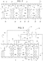
- FIG. 3 - 6 show the addition of an example cooling system 46 for efficiently extracting heat generated by the computers 14 during normal operation without interfering with the fire suppression system 34 during a fire 48 ( FIG. 4 ).
- the cooling system 46 includes an air filter 50, a known cooling coil 52 (e.g., a water, glycol, or refrigerant cooled heat exchanger), a blower system 54, a supply air manifold 56, at least one branch air duct 58, at least one supply air duct 60, at least one return air register 62, and a return air manifold 64.
- the term, "blower system” refers to one or more blowers 66 powered by at least one motor 68.
- the supply air duct 60 is inflatable by virtue of its tubular wall 70 (e.g., 70a and 70b) being made of a pliable material (e.g. air permeable sheet, air impermeable sheet, nonmetallic sheet, coated fabric, uncoated fabric, and various combinations thereof).
- a pliable material e.g. air permeable sheet, air impermeable sheet, nonmetallic sheet, coated fabric, uncoated fabric, and various combinations thereof.
- pliable refers to a material that can be crumpled and later straightened without appreciable damage to the material.
- inflatable as it relates to an air duct means that the duct's internal volume expands with internal air pressure and tends to collapse when the pressure is removed.
- the blower 66 draws air 72 from the return air manifold 64, through the filter 50, and through the cooling coil 52. The blower 66 then discharges the filtered cool air through the supply air manifold 56, through the branch air ducts 58 and into an axial end 74 of each supply air duct 60.
- the discharge pressure of blower 66 inflates or fully expands each supply air duct 60.
- the supply air duct 60 in its expanded state as shown in the examples of FIGS. 3 and 5 , creates an obstruction that substantially fills or blocks gap 32 between the top surface 28 and the overhead surface 30.
- the supply air duct 60 spans the entire gap 32 so as to be in contact with both the top surface 28 and the overhead surface 30 when inflated.
- the supply air duct 60 blocking the gap 32 reduces (e.g., minimizes) the mixing of cold and warm air between the cold aisle 20a and the hot aisle 22a.
- each supply air duct 60 has an air permeable sidewall 70a facing the cold aisle 20a and a substantially impermeable opposite sidewall 70b facing the hot aisle 22a.
- the sidewall 70a is made permeable by any suitable means, examples of which include porosity in the material of the tubular wall 70a, perforations in the tubular wall 70a, and/or the sidewall 70a having one or more nozzles 76 ( FIGS. 18 and 19 ).
- air discharged from the blower 66 flows lengthwise 78 ( FIG. 5 ) through the supply air duct 60, radially outward through the sidewall 70a, and downward into the cold aisle 20a.
- the cool air flows through the computers 14 via an air passageway 80 (through the computers 14 and/or through the cabinets 16), into the hot aisle 22a, and downward toward the return register 62.
- the register 62 conveys the air from the hot aisle 22a into the return manifold 64, which returns the air back to the filter 50 for recirculation.
- the sensor 40 responds by sending the signal 42 to activate the fire suppression system 34, as described earlier, and also sends a signal 82 that de-energizes the motor 68 and, thus, stops the blower 66. Stopping the blower 66 depressurizes the supply air duct 60, which causes the supply air duct 60 to collapse to its deflated state, as shown in FIGS. 4 and 6 . In the deflated state, the collapsed supply air duct 60 opens or substantially unblocks the gap 32 so that the fire extinguishing fluid 38 in a gaseous state can readily disperse over, around and through the multiple rows of computers 18.
- a fire-related incident e.g., flame, smoke, heat, manually triggered fire alarm, etc.
- the cooling system 46 includes means for preventing a collapsed supply air duct 60 from drooping excessively over the sides of the cabinets 16 and/or the computers 14.
- an internal restraint 84 e.g., a string, a strap, a cable, a chain, a horizontal sheet, an elastic cord, a tie rod, etc. limits the radially outward movement of the sidewalls 70a and 70b as the supply air ducts 60 deflate.
- FIG. 7 shows the supply air duct 60 in its inflated state
- FIG. 8 shows the supply air duct 60 in its deflated state.
- a pair of taut internal or external restraints (e.g., cables) running parallel to the supply air duct 60 extend along the entire length of the sidewalls 70a and 70b.
- the supply air duct 60 rests upon the top surface 28 such that the weight of the supply air duct is supported by the top surface 28.
- the supply air duct 60 is secured to the top surface 28 to prevent the supply air duct 60 from sliding off the edge of the top surface 28 of the cabinets 16.
- a bottom 86 of the supply air duct 60 rests upon a basket (not shown) rather than directly on the top surface 28 of the cabinets 16, wherein the basket is wider than the top surface 28 of the cabinets 16.
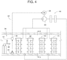
- FIGS. 9 and 10 show an example cooling system 88 with a supply air duct 90 installed lengthwise (i.e., duct 90 is elongate in a direction parallel to the aisles) over the first cold aisle 20a, between the rows of computer 18a and 18b.
- the supply air duct 90 has a pliable tubular wall 92 that renders the duct 90 inflatable, so the duct 90 has selectively an inflated state ( FIG. 9 ) and a deflated state ( FIG. 10 ).
- the supply air duct 90 has an air permeable lower section 94 for delivering cool supply air into the cold aisle 20a.
- the supply air duct 90 has an air impermeable upper section 95 and at least one wing 96 (e.g., a first wing 96a and a second wing 96b) extending from the supply air duct 90 toward an adjacent row of computers 18.
- the first wing 96a extends laterally from the supply air duct 90 to a first top surface 28 of the first row of computers 18a (and/or its associated cabinet 16)
- the second wing 96b extends to a second top surface 28 of the second row of computers 18b (and/or its associated cabinet 16).
- the wings 96 extend lengthwise substantially the full length of the rows of computer 18 and are made of a pliable sheet of material held taut by having distal edges 98a, 98b fastened to the cabinets 16 of the computer rows 18.
- the supply air duct 90 is installed at each cold aisle, so when the blower 66 is activated during normal operation, a first supply current of air 100 flows sequentially from the second aisle 22a (the first hot aisle), through the return register 62, through the return air manifold 64, through the filter 50, through the cooling coil 52, through the blower 66, through the supply air manifold 56, lengthwise through the first supply air duct 90, and downward from the first supply air duct 90 into the first aisle 20a (the cold aisle).
- a second supply current of air 102 flows sequentially from the third aisle 22b (the second hot aisle), through the return register 62, through the return air manifold 64, through the filter 50, through the cooling coil 52, through the blower 66, through the supply air manifold 56, lengthwise through the supply air duct 90, and downward from the supply air duct 90 into the first aisle 20a (the cold aisle).
- the relatively cool air in the first aisle 20a supplies a first current of air 26a flowing through the first row of computers 18a to the second aisle 22a and further supplies a second current of air 26b flowing through the second row of computers 18b to the third aisle 22b.
- the sensor 40 deactivates the blower 66 in some examples, which causes the supply air duct 90 to collapse to its deflated state, as shown in FIG. 10 .
- the collapsed supply air duct 90 opens or unblocks the gap 32 to facilitate the dispersion of the fire extinguishing fluid 38.
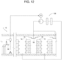
- FIGS. 11 and 12 show an example cooling system 108 that is similar to the system 88 of FIGS. 9 and 10 .
- the supply air duct 90 is elevated to place the wings 96 above and spaced apart from the computer rows 18.
- the vertical spacing further facilitates the dispersion of the fire extinguishing fluid 38 when needed while reducing the amount of warm air above the supply air duct 90 (e.g., above the wings 96) from being entrained by the cooler air dispersed from the bottom of the supply air duct 90 (e.g., below the wings 96) into the cold aisle.
- FIG. 11 shows the supply air duct 90 in its inflated state
- FIG. 12 shows the supply air duct 90 in its deflated state.
- the wing 96 extends lengthwise substantially the full length of the rows of computer 18 and is made of a pliable sheet of material.
- the supply air duct 90 can be supported and the wings 96 can be held taut by any suitable means, such as by a taut cable, a track, struts, and/or combinations thereof.
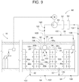
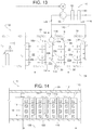
- FIGS. 13 - 15 show an example cooling system 110 that provides a more concentrated discharge of cool supply air directly in the cold aisles 20, thereby reducing (e.g., minimizing) the mixing of cool air with warmer air in the hot aisles 22.
- a supply air duct 112 with a plurality of branch air ducts 114 are installed in each cold aisle 20.
- FIGS. 13 and 14 show at least one of the air ducts in an inflated state
- FIG. 15 shows at least one of them in a deflated state.
- the supply air duct 112 is elevated with an upper section 116 that is higher than the top surface 28 of the rows of computer 18 to provide head clearance for personnel in the area and to facilitate the dispersion of the fire extinguishing fluid 38 when needed.
- a lowermost distal point 118 of the branch air duct 114 extends lower than the top surface 28 of the computer rows 18, and the distal point 118 lies within a certain row length 120 of the row of computers 18. That is, the distal point 118 is positioned within a length of the cold aisle 20 defined by ends of the row of computers 18.
- the branch air ducts 114 include an air permeable tubular wall 122 made of a pliable material so that personnel working in the aisle can simply shove branch air ducts aside to gain unobstructed access to the computers 14.
- a main current of air 124 flows sequentially from the second aisle 22a (the first hot aisle), through the return air register 62, through the return air manifold 64, through the filter 50, through the cooling coil 52, through the blower 66, through the supply air manifold 126, into the supply air duct 112, lengthwise through the supply air duct 112, downward from the supply air duct 112 through the branch air ducts 114, and outward from the branch air ducts 114 into the first aisle 20a (the cold aisle).
- the main current of air 124 in the first aisle 20a supplies a first current of air 26a through the first row of computers 18a and a second current of air 26b through the second row of computers 18b.
- FIGS. 16 and 17 show an example cooling system 128 that has an air duct 130 (e.g., air duct 130a and 130b) atop each row of computers 18, wherein the air duct 130 has a longitudinal internal web 132 (e.g., first web 132a in the first air duct 130a and second web 132b in the second air duct 130b) that separates each air duct 130 into a supply chamber 134 (e.g., 134a and 134b) and a return chamber 136 (e.g., 136a and 136b).
- a supply chamber 134 e.g., 134a and 134b
- return chamber 136 e.g., 136a and 136b
- the air duct 130 has a pliable tubular wall 138 that is air permeable to pass air from the hot aisle 22a into the return chamber 136 and to release air from the supply chamber 134 to the cold aisle 20a.
- the blower 66 and the internal fans 25 drive the movement of air.
- the air duct 130 includes some form of framework 140 that holds the air duct 130 in an expanded shape. Examples of the framework 140 include a plurality of rigid hoops, a longitudinal tensioning device, and combinations thereof.
- the first row of computers 18a is between the first aisle 20a (the cold aisle) and the second aisle 22a (the first hot aisle)
- the second row of computers 18b is between the first aisle 20a (the cold aisle) and the third aisle 22b (the second hot aisle).
- the cooling system 128 includes the first air duct 130a atop the first row of computers 18a, the second air duct 130b atop the second row of computers 18b, the first web 132a dividing the first air duct 130a into a first return chamber 136a and a first supply chamber 134a, the second web 132b dividing second the air duct 130b into a second return chamber 136b and a second supply chamber 134b, the blower system 54, a first fan 25a for urging a first current of air 26a through the first row of computers 18a, and a second fan 25b for urging a second current of air 26b through the second row of computers 18b.
- the blower system 54 draws air from the second aisle 22a (the first hot aisle) into the first return chamber 136a, the blower system 54 urges air from the first return chamber 136a into the first supply chamber 134a via a network of air ducts 142, and the blower system 54 urges air from the first supply chamber 134a into the first aisle 20a (the cold aisle).
- the blower system 54 draws air from the third aisle 22b (the second hot aisle) into the second return chamber 136b, the blower system 54 urges air from the second return chamber 136b into the second supply chamber 134b via the air ducts 142, and the blower system 54 urges air from the second supply chamber 134b into the first aisle 20a (the cold aisle).
- FIGS. 18 and 19 show an example adjustable or fixed-position nozzle 76 that can be used to direct a main current of air 144 discharged from the nozzle. Further, the example nozzle 76 can also be used for inducing surrounding air currents 146 to flow in the same general direction as the main current of air 144. In some examples, the surrounding air currents 146 are from the air released through the air permeable sidewall of a pliable air duct in the area surrounding the nozzle 76. The nozzle 76 and the principle of inducing and directing surrounding air currents can be applied to any of the air duct examples shown in FIGS. 3 - 23 .
- FIGS. 20 - 23 show example internal baffles 198, 200 that can be used to reduce negative effects that might otherwise result due to the dynamic air pressure of unrestricted air rushing axially through a supply air duct 202, 204.
- air released through the air permeable sidewall of the ducts 202, 204 might tend to follow the axial longitudinal direction of the air flowing lengthwise through the duct rather than discharging from the duct in an often more desirable radial direction (perpendicular to the duct's length).
- the internal baffles 198, 200 interrupt the axial or longitudinal velocity of the air entering axial at the end 74 of the corresponding supply air ducts 202, 204.
- the internal baffles 198, 200 may be applied to any of the air duct examples shown in FIGS. 3 - 23 .
- the supply air duct 202 includes an air permeable pliable outer wall 206 and the internal baffle 198 that is horizontally elongate.
- the internal baffle 198 is tubular (e.g., conical or cylindrical).
- the internal baffle 198 separates an interior space of the supply air duct 202 into an inner upstream chamber 208 and an outer downstream chamber 210.
- a supply current of air 212 flows sequentially from the second aisle 22a (a hot aisle) through a cooling system, lengthwise through the upstream chamber 208, radially outward through the internal baffle 198, through the downstream chamber 210, radially outward through an air permeable pliable outer wall 214 of the supply air duct 202, and downward from the supply air duct 202 into the first aisle 20a (a cold aisle).
- the air may then pass through the row of computers 18a and into second aisle 22a (the hot aisle).
- the cooling system includes the return register 62, the blower system 54, and suitable ductwork to return the air back to the upstream chamber 208 at the axial end 74 of the supply air duct 202 to repeat the circuit.
- the supply air duct 204 includes an air permeable pliable outer wall 216 and the internal baffle 200 that is horizontally elongate.
- the internal baffle 200 is generally planar.
- the internal baffle 200 separates an interior space of supply air duct 204 into an inner upstream chamber 218 and an outer downstream chamber 220.
- a supply current of air 212 flows sequentially from the second aisle 22a (a hot aisle) through a cooling system, lengthwise through the upstream chamber 218, radially outward through the internal baffle 200, through the downstream chamber 220, radially outward through an air permeable pliable outer wall 222 of the supply air duct 204, and downward from the supply air duct 204 into the first aisle 20a (cold aisle).
- the air may then pass through the row of computers 18a and into second aisle 22a (the hot aisle).
- the cooling system includes the return register 62, the blower system 54, and suitable ductwork to return the air back to the upstream chamber 218 at the axial end 74 to repeat the circuit.
- FIGS. 24 and 25 show an example cooling system 224 with a supply air duct 226 installed above the first cold aisle 20a, between the rows of computer 18a, 18b.
- the supply air duct 226 has a pliable tubular wall 228 that renders the duct 226 inflatable.
- the supply air duct 226 has an air permeable lower section 229 for delivering conditioned (e.g., cool) air into the cold aisle 20a.
- the entire pliable tubular wall 228 may be air permeable.
- adjustable or fixed-position nozzles 230 are attached to the wall 228 of the supply air duct 226 similar to those shown in FIGS. 18 and 19 .
- the nozzles 230 provide a discharge path through which a main discharge current of air 232 is directed out from an interior of the supply air duct 226 toward the cold aisle 20a.
- the nozzles 230 are structured to entrain surrounding air currents 234 to flow in the same general direction as the main discharge current of air 232. More particularly, in some examples, the surrounding air currents 234 entrained by the main current of air 232 from the nozzles 230 correspond to the air passing through the air permeable portion of the tubular wall 228 of the supply air duct 226.
- the nozzles 230 are positioned on the air duct 226 such that the wall 228 surrounding the nozzle is air permeable.
- the nozzles 230 are structured and positioned to entrain conditioned air passing through the air permeable wall 228 without entraining warmer ambient air 236 above the rows of computers 18.
- a majority of the air delivered by the supply air duct 226 is provided through the discharge path. In other examples, a majority of the air delivered by the supply air duct is provided through the air permeable portion of the wall 228.
- the supply air duct 226 includes an internal baffle 238 that is horizontally elongate.
- the internal baffle 238 is similar in construction to the tubular (e.g., conical or cylindrical) internal baffle 198 described above in connection with FIGS. 20 and 22 . That is, the internal baffle 238 is air permeable and serves to increase the even distribution of conditioned air along the air duct 226 passing through the air permeable outer wall 228 into the cold aisle 20a.
- the even distribution of air flow enables the temperature within the cold aisle 20a to be substantially uniform along the length of the cold aisle 20a (e.g., within +/- 2 degrees Fahrenheit of the temperature of air exiting the supply air duct 226 (i.e., the temperature of the air currents 232, 234)).
- the air duct 226 begins and ends beyond the beginning and ending of the cold aisle 20a. That is, as shown in FIG. 25 , an upstream end 240 of the supply air duct 226 is positioned outside a first end 242 of the row of computers 18 while a downstream end 244 of the supply air duct 226 is positioned outside of a second end 246 of the row of computers 18. In some examples, ones of the nozzles 230 may be positioned proximate to the upstream and downstream ends 240, 244 of the supply air duct 226 to be beyond the first and second ends 242, 246 of the row of computers 18.
- the supply air duct 226 is spaced apart and disconnected from the rows of computers 18 such that the cold aisle 20a is in unobstructed fluid communication with the adjacent hot aisles 22a, 22b over the top of the rows of computers 18. That is, unlike the example of FIGS. 9 and 10 that show wings 96 connecting the air duct 90 to the rows of computers 18a, 18b, the air duct 226 in the example of FIGS. 24 and 25 is not connected to the rows of computers 18a, 18b. This configuration reduces the complexity of the cooling system 224 relative to FIG. 9 . Furthermore, the unobstructed fluid paths over top of the rows of computers 18 enables the fire extinguishing fluid 38 ( FIG. 4 ) in a gaseous state to readily disperse over, around and through the multiple rows of computers 18, regardless of whether the air duct 226 is inflated or deflated.
- the internal baffle 238 substantially evenly distributes the release of conditioned air along the length of the aisle 20 and the nozzles 230 are structured to entrain the conditioned air passing through the permeable wall 228 of the supply air duct 226, the mixing of the ambient air 236 and the conditioned air will be reduced and/or substantially prevented without a structural barrier above the rows of computers 18 to partition the different aisles 20, 22.
- reducing the mixing of warm air in the hot aisles 22 and above the rows of computers 18 (e.g., the ambient air 236) with the cool conditioned air within the cold aisle 20 depends upon the internal fans 25 associated with the rows of computers 18 being able to adequately blow air from the cold aisle 20a to the hot aisles 22a, 22b as the cold aisle 20a receives conditioned air via the supply air duct 226.
- the internal fans 25 can adequately move the air when a velocity of air within the cold aisle 20a in a direction 250 parallel to the facing surfaces of the rows of computers 18 (e.g., in a direction crossing an inlet 252 of the air passageway 24 between the cold aisle 20a and the hot aisles 22a, 22b) is maintained below a threshold in a region adjacent the facing surfaces of the rows of computers 18. More particularly, in some examples, in a region immediately adjacent (e.g., within approximately 1 inch of) the inlets 252 on the facing surfaces of the rows of computers 18 the velocity of air is maintained at or below approximately 400 feet per minute. In a region between approximately 1 inches and 10 inches from the inlets 252, the velocity may reach up to 1000 feet per minute.
- FIG. 26 is a cross-sectional view similar to FIG. 24 but showing another example cooling system 254 with a supply air duct 256 constructed in accordance with the teachings disclosed herein.
- the example cooling system 254 operates on the same principle as the example of FIG. 24 described above. That is, the position and design of the supply air duct 256 is such that the mixing of ambient air 258 above the rows of computers 18 is substantially prevented through the use of an internal baffle 260 to evenly distribute conditioned air passing delivered by the supply air duct 256 and nozzles 262 to discharge a main current of air that entrains surrounding air passing through the permeable wall of the supply air duct 256.
- the internal baffle is similar to the generally planar internal baffle 200 described above in connection with FIGS.
- the nozzles 262 of FIG. 26 may be similar to the nozzles 230 of FIGS. 24 and 25 . However, as shown in the illustrated example, the nozzles 262 are located in a different position and directed at a different angle.
- the nozzles 230, 262 of FIGS. 24-26 may be placed in other locations along the corresponding air ducts 226, 256 and directed at suitable angles depending upon the particular circumstances in which the nozzles 230, 262 are to be implemented.
- the bottom 248 of the air duct 226 of FIGS. 24 and 25 is positioned a distance 249 above the top surface 28 of the rows of computers 18, the bottom of the air duct 256 of FIG. 26 is below the top surface 28 of the rows of computers 18.
- the lower air duct 256 in the illustrated example of FIG. 26 , is spaced apart from the overhead surface (ceiling) 30 of the building 12 but connected thereto by an overhead support structure 264.
- the ambient air 258 on either side of the air duct 256 may be in fluid communication over top of the air duct 256.
- the air duct 256 should not affect the ability of the air duct 256 to substantially prevent the ambient air 258 from mixing with the conditioned (e.g., cool) air in the cold aisle 20a.
- testing has shown that when a bottom 248 of the air duct 226 is below the top surface 28 of the rows of computers 18 a distance 259 less than or equal to about 6 inches the ambient air 258 above the rows of computers 18 can be substantially prevented from mixing with the cool conditioned air within the cold aisle 20a when constructed as shown and described above.
- the bottom of either air duct 226, 256 of FIGS. 24-26 is approximately level with the top surface 28 of the rows of computers 18.
Landscapes
- Engineering & Computer Science (AREA)
- Microelectronics & Electronic Packaging (AREA)
- Physics & Mathematics (AREA)
- Thermal Sciences (AREA)
- Aviation & Aerospace Engineering (AREA)
- Computer Hardware Design (AREA)
- General Engineering & Computer Science (AREA)
- Ventilation (AREA)
- Cooling Or The Like Of Electrical Apparatus (AREA)
Claims (11)
- Kühlsystem, umfassend:einen aufblasbaren Luftkanal (226), der über einem kalten Gang (20a), der zwischen zwei Reihen von elektronischen Geräten (18a, 18b) definiert ist, zu positionieren ist, wobei sich der aufblasbare Luftkanal entlang einer Länge des kalten Gangs (20a) erstreckt, wobei der aufblasbare Luftkanal (226) luftdurchlässig ist, um klimatisierte Luft in den kalten Gang (20a) zu liefern, wobei die elektronischen Geräte Lüfter aufweisen, um kalte Luft innerhalb des kalten Gangs (20a) durch die elektronischen Geräte zu benachbarten heißen Gängen (22a, 22b) auf gegenüberliegenden Seiten der beiden Reihen der elektronischen Geräte (18a, 18b) zu treiben, wobei der aufblasbare Luftkanal (226) von den Reihen der elektronischen Geräte (18a, 18b) so beabstandet ist, dass der kalte Gang (20a) in ungehinderter Fluidverbindung mit den benachbarten heißen Gängen (22a, 22b) über die Oberseiten der Reihen der elektronischen Geräte (18a, 18b) steht, wobei die von dem aufblasbaren Luftkanal (226) gelieferte klimatisierte Luft dazu eingerichtet ist, um eine Vermischung von warmer Luft in den heißen Gängen (22a, 22b) mit der kalten Luft in dem kalten Gang (20a) zu reduzieren; undeine innere Ablenkplatte (238), die sich entlang einer Innenseite des aufblasbaren Luftkanals (226) erstreckt, um die gleichmäßige Verteilung der klimatisierten Luft, die entlang einer Länge des aufblasbaren Luftkanals (226) abgegeben wird, zu erhöhen.
- Kühlsystem nach Anspruch 1, bei dem die innere Ablenkplatte (238) so ausgestaltet ist, dass die gleichmäßige Verteilung der klimatisierten Luft die kühle Luft auf einer im Wesentlichen gleichmäßigen Temperatur entlang der Länge des Ganges hält, die innerhalb von 2°F einer Temperatur der klimatisierten Luft liegt, die von dem aufblasbaren Luftkanal (226) geliefert wird.
- Kühlsystem nach Anspruch 1, bei dem eine Luftgeschwindigkeit innerhalb des kalten Ganges (20a) in einer Richtung, die sich parallel zu gegenüberliegenden Oberflächen der beiden Reihen der elektronischen Geräte (18a, 18b) und in einem Bereich innerhalb von etwa 1 Zoll der gegenüberliegenden Oberflächen erstreckt, auf oder unter etwa 400 Fuß pro Minute gehalten wird.
- Kühlsystem nach Anspruch 1, weiterhin enthaltend eine Düse (230), die an einer Wand des aufblasbaren Luftkanals (226) anzubringen ist, wobei die Düse (230) einen Auslassweg für die aufbereitete Luft aus einem Inneren des aufblasbaren Luftkanals (226) in Richtung des kalten Ganges (20a) bereitstellt, wobei die Düse (230) einen Luftauslassstrom durch den Auslassweg leitet.
- Kühlsystem nach Anspruch 4, bei dem die die Düse umgebende Wand (228) (230) luftdurchlässig sein soll, wobei der Luftauslassstrom zum Mitführen der klimatisierten Luft die luftdurchlässige Wand (228) durchströmt.
- Kühlsystem nach Anspruch 5, bei dem die Geschwindigkeit des Luftauslassstroms nicht ausreicht, um Umgebungsluft über den beiden Reihen der elektronischen Geräte (18a, 18b) mitzuführen.
- Kühlsystem nach Anspruch 1, wobei sich mindestens ein stromaufwärtiges Ende des aufblasbaren Luftkanals (226) oder ein stromabwärtiges Ende des aufblasbaren Luftkanals (226) über ein Ende des kalten Ganges (20a) hinaus erstreckt.
- Kühlsystem nach Anspruch 1, wobei ein Boden des aufblasbaren Luftkanals (226) weniger als etwa 6 Zoll unter der Höhe einer Oberseite von Gehäusen liegen soll, die die beiden Reihen der elektronischen Geräte (18a, 18b) definieren.
- Kühlsystem nach Anspruch 1, wobei ein Boden des aufblasbaren Luftkanals (226) weniger als etwa 30 Zoll über einer Höhe einer Oberseite der beiden Reihen der elektronischen Geräte (18a, 18b) liegen soll.
- Kühlsystem nach Anspruch 1, wobei ein unterer Abschnitt des aufblasbaren Luftkanals (226) durchlässiger ist als ein oberer Abschnitt des aufblasbaren Luftkanals (226).
- Kühlsystem gemäß einem der vorhergehenden Ansprüche, für ein Rechenzentrum in einem Gebäude.
Priority Applications (3)
| Application Number | Priority Date | Filing Date | Title |
|---|---|---|---|
| DK20173933.1T DK3713382T3 (da) | 2016-09-09 | 2017-09-05 | Kølesystemer til enheder, der er anbragt i rækker |
| EP20173933.1A EP3713382B1 (de) | 2016-09-09 | 2017-09-05 | Kühlsysteme für in reihe angeordnete vorrichtungen |
| EP23170720.9A EP4236647A1 (de) | 2016-09-09 | 2017-09-05 | Kühlsysteme für in reihen angeordnete vorrichtungen |
Applications Claiming Priority (2)
| Application Number | Priority Date | Filing Date | Title |
|---|---|---|---|
| US15/261,280 US10251312B2 (en) | 2016-09-09 | 2016-09-09 | Cooling systems for devices arranged in rows |
| PCT/US2017/050092 WO2018048804A1 (en) | 2016-09-09 | 2017-09-05 | Cooling systems for devices arranged in rows |
Related Child Applications (2)
| Application Number | Title | Priority Date | Filing Date |
|---|---|---|---|
| EP23170720.9A Division EP4236647A1 (de) | 2016-09-09 | 2017-09-05 | Kühlsysteme für in reihen angeordnete vorrichtungen |
| EP20173933.1A Division EP3713382B1 (de) | 2016-09-09 | 2017-09-05 | Kühlsysteme für in reihe angeordnete vorrichtungen |
Publications (2)
| Publication Number | Publication Date |
|---|---|
| EP3510848A1 EP3510848A1 (de) | 2019-07-17 |
| EP3510848B1 true EP3510848B1 (de) | 2020-05-27 |
Family
ID=59846753
Family Applications (3)
| Application Number | Title | Priority Date | Filing Date |
|---|---|---|---|
| EP20173933.1A Active EP3713382B1 (de) | 2016-09-09 | 2017-09-05 | Kühlsysteme für in reihe angeordnete vorrichtungen |
| EP23170720.9A Pending EP4236647A1 (de) | 2016-09-09 | 2017-09-05 | Kühlsysteme für in reihen angeordnete vorrichtungen |
| EP17765057.9A Active EP3510848B1 (de) | 2016-09-09 | 2017-09-05 | Kühlsysteme für in reihe angeordnete vorrichtungen |
Family Applications Before (2)
| Application Number | Title | Priority Date | Filing Date |
|---|---|---|---|
| EP20173933.1A Active EP3713382B1 (de) | 2016-09-09 | 2017-09-05 | Kühlsysteme für in reihe angeordnete vorrichtungen |
| EP23170720.9A Pending EP4236647A1 (de) | 2016-09-09 | 2017-09-05 | Kühlsysteme für in reihen angeordnete vorrichtungen |
Country Status (8)
| Country | Link |
|---|---|
| US (1) | US10251312B2 (de) |
| EP (3) | EP3713382B1 (de) |
| CN (1) | CN109691254B (de) |
| AU (1) | AU2017324277B2 (de) |
| CA (1) | CA3035838C (de) |
| DK (2) | DK3510848T3 (de) |
| MX (1) | MX386369B (de) |
| WO (1) | WO2018048804A1 (de) |
Families Citing this family (14)
| Publication number | Priority date | Publication date | Assignee | Title |
|---|---|---|---|---|
| US9723760B2 (en) * | 2007-11-13 | 2017-08-01 | International Business Machines Corporation | Water-assisted air cooling for a row of cabinets |
| US9901011B2 (en) | 2015-11-04 | 2018-02-20 | Rite-Hite Holding Corporation | Cooling systems for devices arranged in rows |
| US10736231B2 (en) * | 2016-06-14 | 2020-08-04 | Dell Products L.P. | Modular data center with passively-cooled utility module |
| US10856449B2 (en) * | 2016-12-02 | 2020-12-01 | Dell Products L.P. | Dynamic cooling system |
| DE102017115702A1 (de) * | 2017-07-12 | 2019-01-17 | Dr. Ing. H.C. F. Porsche Aktiengesellschaft | Gehäuse für eine Stromtankstelle und Verfahren zu dessen Herstellung |
| US10299412B1 (en) | 2018-08-02 | 2019-05-21 | Core Scientific, Inc. | System and method for cooling computing devices within a facility |
| US10908658B2 (en) * | 2018-08-02 | 2021-02-02 | Core Scientific, Inc. | System and method for cooling computing devices within a facility |
| CN118201323A (zh) * | 2018-10-02 | 2024-06-14 | 瑞泰控股公司 | 用于数据中心区域隔离的空气屏障系统 |
| FR3088519B1 (fr) * | 2018-11-20 | 2020-12-18 | Ynsect | Régulation en température d’une zone climatique d’un atelier d’élevage d’insectes |
| US11516942B1 (en) | 2020-10-16 | 2022-11-29 | Core Scientific, Inc. | Helical-configured shelving for cooling computing devices |
| US11812588B2 (en) | 2020-11-02 | 2023-11-07 | Core Scientific Operating Company | Managing airflow for computing devices |
| US10959349B1 (en) | 2020-11-02 | 2021-03-23 | Core Scientific, Inc. | Dynamic aisles for computing devices |
| US12287683B2 (en) | 2020-11-02 | 2025-04-29 | Core Scientific, Inc. | Thermal management for container-based data centers |
| US12146685B1 (en) * | 2021-07-14 | 2024-11-19 | Core Scientific, Inc. | System and method for using waste heat from computing devices |
Family Cites Families (47)
| Publication number | Priority date | Publication date | Assignee | Title |
|---|---|---|---|---|
| US2013724A (en) | 1934-05-07 | 1935-09-10 | Bemis Bro Bag Co | Fabric tubing |
| SE315091B (de) | 1968-11-12 | 1969-09-22 | Svenska Flaektfabriken Ab | |
| US3824909A (en) | 1970-04-08 | 1974-07-23 | Cgt Corp | Distribution system for clean rooms |
| US3699872A (en) | 1971-03-01 | 1972-10-24 | Keene Corp | Air distribution apparatus |
| US3726203A (en) | 1971-06-23 | 1973-04-10 | Svenska Flaektfabriken Ab | Device for maintenance of a dustfree, bacteria-free zone in a room |
| DE2707779C3 (de) | 1977-02-23 | 1980-03-20 | Philipp Kreis Gmbh & Co Truma-Geraetebau, 8000 Muenchen | Belüftungsrohr sowie Anordnung desselben in einem Wohnwagen |
| GB2120778A (en) | 1982-05-20 | 1983-12-07 | Howorth Air Eng Ltd | Outlet device for an air conditioning system |
| FI78548C (fi) | 1986-12-30 | 1989-08-10 | Halton Oy | Luftfoerdelningssystem. |
| US5137057A (en) | 1989-05-26 | 1992-08-11 | Hummert Iii August H | Flexible duct and method of suspending a duct |
| AU617951B2 (en) | 1989-07-24 | 1991-12-05 | Acme Group Pty Ltd | Flexible ducting |
| US5044259A (en) * | 1989-10-23 | 1991-09-03 | Dynaforce Corporation | Air diffusion system capable of limited area control and adapted for supplying make-up air to an enclosure |
| US5111739A (en) | 1989-11-13 | 1992-05-12 | Hall James F | Air flow control system |
| DK12792D0 (da) | 1992-02-03 | 1992-02-03 | Ke Safematic As | Ventilationssystem |
| FR2748048B1 (fr) | 1996-04-25 | 1998-07-31 | Air Strategie | Gaine textile pour la protection rapprochee du convoyage de produits sensibles et hotte a flux laminaire comportant une telle gaine |
| FR2759153B1 (fr) | 1997-01-31 | 1999-04-16 | Diffusion Thermique Ouest Sa | Systeme de diffusion d'air notamment pour le chauffage, le rafraichissement, l'humidification ou la ventilation d'un local |
| DE20010135U1 (de) | 2000-06-06 | 2000-08-24 | LTG Aktiengesellschaft, 70435 Stuttgart | Rohrluftauslass |
| US6558250B1 (en) | 2000-10-23 | 2003-05-06 | Nicolas B. Paschke | Fabric flow restriction and method for restricting a fabric duct |
| FR2824626B1 (fr) | 2001-05-14 | 2004-04-16 | Pierre Bridenne | Procede et dispositif pour diffuser un flux de protection a l'egard d'une ambiance environnante |
| US6626754B2 (en) | 2001-07-27 | 2003-09-30 | Rite-Hite Holding Corporation | Conical air filter |
| US6565430B2 (en) | 2001-09-13 | 2003-05-20 | Rite-Hite Holding Corporation | Pliable air duct with dust and condensation repellency |
| GB0207382D0 (en) * | 2002-03-28 | 2002-05-08 | Holland Heating Uk Ltd | Computer cabinet |
| SE526035C2 (sv) | 2002-09-04 | 2005-06-21 | Johnson Medical Dev Pte Ltd | System, anordning och metod för ventilation |
| US6960130B2 (en) | 2003-05-12 | 2005-11-01 | Rite-Hite Holding Corporation | Fabric air duct with directional vent |
| US20060252365A1 (en) | 2005-05-04 | 2006-11-09 | Gebke Kevin J | Pliable air duct with pressure responsive discharge outlets |
| US8764528B2 (en) * | 2006-04-27 | 2014-07-01 | Wright Line, Llc | Systems and methods for closed loop heat containment with cold aisle isolation for data center cooling |
| CA2653808C (en) | 2006-06-01 | 2014-10-14 | Exaflop Llc | Controlled warm air capture |
| US7564685B2 (en) | 2006-12-29 | 2009-07-21 | Google Inc. | Motherboards with integrated cooling |
| US20080176506A1 (en) | 2007-01-22 | 2008-07-24 | Rite-Hite Holding Corporation | Fabric diffuser with programmed airflow |
| US20080291625A1 (en) | 2007-05-21 | 2008-11-27 | Rathbun Ii Dale | Direct cooling system |
| US7430118B1 (en) | 2007-06-04 | 2008-09-30 | Yahoo! Inc. | Cold row encapsulation for server farm cooling system |
| US8037644B2 (en) | 2008-01-07 | 2011-10-18 | International Business Machines Corporation | Fire-code-compatible, collapsible partitions to prevent unwanted airflow between computer-room cold aisles and hot aisles |
| US8583289B2 (en) | 2008-02-19 | 2013-11-12 | Liebert Corporation | Climate control system for data centers |
| US10274216B2 (en) | 2008-08-22 | 2019-04-30 | Rite-Hite Holding Corporation | Under-floor pliable air duct/dispersion systems |
| US9072200B2 (en) | 2008-09-10 | 2015-06-30 | Schneider Electric It Corporation | Hot aisle containment panel system and method |
| WO2010095931A1 (en) | 2009-02-19 | 2010-08-26 | J.C.A. Van De Pas Holding B.V. | A method for cooling an ict room, as well as a separation element |
| US9494336B2 (en) | 2010-05-03 | 2016-11-15 | Rite-Hite Holding Corporation | Configurable pliable air ducts |
| US20110319006A1 (en) * | 2010-06-29 | 2011-12-29 | Verizon Patent And Licensing Inc. | Vent hood apparatus for data center |
| US8808075B2 (en) | 2010-07-12 | 2014-08-19 | Rite-Hite Holding Corporation | Configurable pliable air ducts |
| US8490709B2 (en) | 2010-09-24 | 2013-07-23 | International Business Machines Corporation | Fire suppression control system and method |
| US8844578B2 (en) | 2010-11-19 | 2014-09-30 | Rite-Hite Holding Corporation | Pliable-wall air ducts with internal expanding structures |
| US9485887B1 (en) | 2012-06-15 | 2016-11-01 | Amazon Technologies, Inc. | Data center with streamlined power and cooling |
| US9709193B2 (en) | 2013-01-24 | 2017-07-18 | Rite-Hite Holding Corporation | Pliable air ducts with anti-condensation nozzles |
| US9894809B1 (en) | 2013-02-28 | 2018-02-13 | Amazon Technologies, Inc. | System for supplying cooling air from sub-floor space |
| US9103117B1 (en) | 2013-02-28 | 2015-08-11 | Windchill Engineering, Inc. | Mechanical drop-away ceiling |
| US9451730B2 (en) | 2013-03-06 | 2016-09-20 | Amazon Technologies, Inc. | Managing airflow supplied through soft ducts |
| US9152191B1 (en) * | 2013-08-13 | 2015-10-06 | Amazon Technologies, Inc. | Mobile soft duct system |
| US9901011B2 (en) | 2015-11-04 | 2018-02-20 | Rite-Hite Holding Corporation | Cooling systems for devices arranged in rows |
-
2016
- 2016-09-09 US US15/261,280 patent/US10251312B2/en active Active
-
2017
- 2017-09-05 EP EP20173933.1A patent/EP3713382B1/de active Active
- 2017-09-05 MX MX2019002740A patent/MX386369B/es unknown
- 2017-09-05 WO PCT/US2017/050092 patent/WO2018048804A1/en not_active Ceased
- 2017-09-05 AU AU2017324277A patent/AU2017324277B2/en active Active
- 2017-09-05 CN CN201780055429.2A patent/CN109691254B/zh active Active
- 2017-09-05 EP EP23170720.9A patent/EP4236647A1/de active Pending
- 2017-09-05 DK DK17765057.9T patent/DK3510848T3/da active
- 2017-09-05 EP EP17765057.9A patent/EP3510848B1/de active Active
- 2017-09-05 CA CA3035838A patent/CA3035838C/en active Active
- 2017-09-05 DK DK20173933.1T patent/DK3713382T3/da active
Non-Patent Citations (1)
| Title |
|---|
| None * |
Also Published As
| Publication number | Publication date |
|---|---|
| MX2019002740A (es) | 2019-06-20 |
| MX386369B (es) | 2025-03-18 |
| CA3035838A1 (en) | 2018-03-15 |
| US20180077822A1 (en) | 2018-03-15 |
| DK3510848T3 (da) | 2020-08-31 |
| AU2017324277B2 (en) | 2020-06-11 |
| US10251312B2 (en) | 2019-04-02 |
| WO2018048804A1 (en) | 2018-03-15 |
| CN109691254B (zh) | 2020-09-08 |
| EP3713382B1 (de) | 2023-06-07 |
| EP4236647A1 (de) | 2023-08-30 |
| AU2017324277A1 (en) | 2019-03-21 |
| EP3510848A1 (de) | 2019-07-17 |
| CN109691254A (zh) | 2019-04-26 |
| CA3035838C (en) | 2021-04-13 |
| EP3713382A1 (de) | 2020-09-23 |
| DK3713382T3 (da) | 2023-09-18 |
Similar Documents
| Publication | Publication Date | Title |
|---|---|---|
| EP3510848B1 (de) | Kühlsysteme für in reihe angeordnete vorrichtungen | |
| EP3372063B1 (de) | Kühlsysteme für in reihe angeordnete vorrichtungen | |
| CN103069229B (zh) | 用于冷却机柜安装式设备的系统及方法 | |
| JP6712274B2 (ja) | データセンタ熱除去システムおよび方法 | |
| JP6096188B2 (ja) | ホットアイル/コールドアイルデータセンター火災抑止のための方法および装置 | |
| KR101665448B1 (ko) | 전산센터 환경유지 시스템 | |
| US9271428B2 (en) | Cooling host module | |
| JP6263359B2 (ja) | 空調システム |
Legal Events
| Date | Code | Title | Description |
|---|---|---|---|
| STAA | Information on the status of an ep patent application or granted ep patent |
Free format text: STATUS: UNKNOWN |
|
| STAA | Information on the status of an ep patent application or granted ep patent |
Free format text: STATUS: THE INTERNATIONAL PUBLICATION HAS BEEN MADE |
|
| PUAI | Public reference made under article 153(3) epc to a published international application that has entered the european phase |
Free format text: ORIGINAL CODE: 0009012 |
|
| STAA | Information on the status of an ep patent application or granted ep patent |
Free format text: STATUS: REQUEST FOR EXAMINATION WAS MADE |
|
| 17P | Request for examination filed |
Effective date: 20190306 |
|
| AK | Designated contracting states |
Kind code of ref document: A1 Designated state(s): AL AT BE BG CH CY CZ DE DK EE ES FI FR GB GR HR HU IE IS IT LI LT LU LV MC MK MT NL NO PL PT RO RS SE SI SK SM TR |
|
| AX | Request for extension of the european patent |
Extension state: BA ME |
|
| DAV | Request for validation of the european patent (deleted) | ||
| DAX | Request for extension of the european patent (deleted) | ||
| GRAP | Despatch of communication of intention to grant a patent |
Free format text: ORIGINAL CODE: EPIDOSNIGR1 |
|
| STAA | Information on the status of an ep patent application or granted ep patent |
Free format text: STATUS: GRANT OF PATENT IS INTENDED |
|
| INTG | Intention to grant announced |
Effective date: 20191220 |
|
| GRAS | Grant fee paid |
Free format text: ORIGINAL CODE: EPIDOSNIGR3 |
|
| GRAA | (expected) grant |
Free format text: ORIGINAL CODE: 0009210 |
|
| STAA | Information on the status of an ep patent application or granted ep patent |
Free format text: STATUS: THE PATENT HAS BEEN GRANTED |
|
| AK | Designated contracting states |
Kind code of ref document: B1 Designated state(s): AL AT BE BG CH CY CZ DE DK EE ES FI FR GB GR HR HU IE IS IT LI LT LU LV MC MK MT NL NO PL PT RO RS SE SI SK SM TR |
|
| REG | Reference to a national code |
Ref country code: GB Ref legal event code: FG4D |
|
| REG | Reference to a national code |
Ref country code: CH Ref legal event code: EP |
|
| REG | Reference to a national code |
Ref country code: AT Ref legal event code: REF Ref document number: 1275990 Country of ref document: AT Kind code of ref document: T Effective date: 20200615 |
|
| REG | Reference to a national code |
Ref country code: DE Ref legal event code: R096 Ref document number: 602017017415 Country of ref document: DE |
|
| REG | Reference to a national code |
Ref country code: NL Ref legal event code: FP |
|
| REG | Reference to a national code |
Ref country code: DK Ref legal event code: T3 Effective date: 20200825 |
|
| REG | Reference to a national code |
Ref country code: LT Ref legal event code: MG4D |
|
| PG25 | Lapsed in a contracting state [announced via postgrant information from national office to epo] |
Ref country code: PT Free format text: LAPSE BECAUSE OF FAILURE TO SUBMIT A TRANSLATION OF THE DESCRIPTION OR TO PAY THE FEE WITHIN THE PRESCRIBED TIME-LIMIT Effective date: 20200928 Ref country code: LT Free format text: LAPSE BECAUSE OF FAILURE TO SUBMIT A TRANSLATION OF THE DESCRIPTION OR TO PAY THE FEE WITHIN THE PRESCRIBED TIME-LIMIT Effective date: 20200527 Ref country code: FI Free format text: LAPSE BECAUSE OF FAILURE TO SUBMIT A TRANSLATION OF THE DESCRIPTION OR TO PAY THE FEE WITHIN THE PRESCRIBED TIME-LIMIT Effective date: 20200527 Ref country code: GR Free format text: LAPSE BECAUSE OF FAILURE TO SUBMIT A TRANSLATION OF THE DESCRIPTION OR TO PAY THE FEE WITHIN THE PRESCRIBED TIME-LIMIT Effective date: 20200828 Ref country code: SE Free format text: LAPSE BECAUSE OF FAILURE TO SUBMIT A TRANSLATION OF THE DESCRIPTION OR TO PAY THE FEE WITHIN THE PRESCRIBED TIME-LIMIT Effective date: 20200527 Ref country code: IS Free format text: LAPSE BECAUSE OF FAILURE TO SUBMIT A TRANSLATION OF THE DESCRIPTION OR TO PAY THE FEE WITHIN THE PRESCRIBED TIME-LIMIT Effective date: 20200927 Ref country code: NO Free format text: LAPSE BECAUSE OF FAILURE TO SUBMIT A TRANSLATION OF THE DESCRIPTION OR TO PAY THE FEE WITHIN THE PRESCRIBED TIME-LIMIT Effective date: 20200827 |
|
| PG25 | Lapsed in a contracting state [announced via postgrant information from national office to epo] |
Ref country code: BG Free format text: LAPSE BECAUSE OF FAILURE TO SUBMIT A TRANSLATION OF THE DESCRIPTION OR TO PAY THE FEE WITHIN THE PRESCRIBED TIME-LIMIT Effective date: 20200827 Ref country code: HR Free format text: LAPSE BECAUSE OF FAILURE TO SUBMIT A TRANSLATION OF THE DESCRIPTION OR TO PAY THE FEE WITHIN THE PRESCRIBED TIME-LIMIT Effective date: 20200527 Ref country code: RS Free format text: LAPSE BECAUSE OF FAILURE TO SUBMIT A TRANSLATION OF THE DESCRIPTION OR TO PAY THE FEE WITHIN THE PRESCRIBED TIME-LIMIT Effective date: 20200527 Ref country code: LV Free format text: LAPSE BECAUSE OF FAILURE TO SUBMIT A TRANSLATION OF THE DESCRIPTION OR TO PAY THE FEE WITHIN THE PRESCRIBED TIME-LIMIT Effective date: 20200527 |
|
| REG | Reference to a national code |
Ref country code: AT Ref legal event code: MK05 Ref document number: 1275990 Country of ref document: AT Kind code of ref document: T Effective date: 20200527 |
|
| PG25 | Lapsed in a contracting state [announced via postgrant information from national office to epo] |
Ref country code: AL Free format text: LAPSE BECAUSE OF FAILURE TO SUBMIT A TRANSLATION OF THE DESCRIPTION OR TO PAY THE FEE WITHIN THE PRESCRIBED TIME-LIMIT Effective date: 20200527 |
|
| PG25 | Lapsed in a contracting state [announced via postgrant information from national office to epo] |
Ref country code: EE Free format text: LAPSE BECAUSE OF FAILURE TO SUBMIT A TRANSLATION OF THE DESCRIPTION OR TO PAY THE FEE WITHIN THE PRESCRIBED TIME-LIMIT Effective date: 20200527 Ref country code: SM Free format text: LAPSE BECAUSE OF FAILURE TO SUBMIT A TRANSLATION OF THE DESCRIPTION OR TO PAY THE FEE WITHIN THE PRESCRIBED TIME-LIMIT Effective date: 20200527 Ref country code: AT Free format text: LAPSE BECAUSE OF FAILURE TO SUBMIT A TRANSLATION OF THE DESCRIPTION OR TO PAY THE FEE WITHIN THE PRESCRIBED TIME-LIMIT Effective date: 20200527 Ref country code: ES Free format text: LAPSE BECAUSE OF FAILURE TO SUBMIT A TRANSLATION OF THE DESCRIPTION OR TO PAY THE FEE WITHIN THE PRESCRIBED TIME-LIMIT Effective date: 20200527 Ref country code: RO Free format text: LAPSE BECAUSE OF FAILURE TO SUBMIT A TRANSLATION OF THE DESCRIPTION OR TO PAY THE FEE WITHIN THE PRESCRIBED TIME-LIMIT Effective date: 20200527 Ref country code: IT Free format text: LAPSE BECAUSE OF FAILURE TO SUBMIT A TRANSLATION OF THE DESCRIPTION OR TO PAY THE FEE WITHIN THE PRESCRIBED TIME-LIMIT Effective date: 20200527 |
|
| PG25 | Lapsed in a contracting state [announced via postgrant information from national office to epo] |
Ref country code: PL Free format text: LAPSE BECAUSE OF FAILURE TO SUBMIT A TRANSLATION OF THE DESCRIPTION OR TO PAY THE FEE WITHIN THE PRESCRIBED TIME-LIMIT Effective date: 20200527 Ref country code: SK Free format text: LAPSE BECAUSE OF FAILURE TO SUBMIT A TRANSLATION OF THE DESCRIPTION OR TO PAY THE FEE WITHIN THE PRESCRIBED TIME-LIMIT Effective date: 20200527 |
|
| REG | Reference to a national code |
Ref country code: DE Ref legal event code: R097 Ref document number: 602017017415 Country of ref document: DE |
|
| PLBE | No opposition filed within time limit |
Free format text: ORIGINAL CODE: 0009261 |
|
| STAA | Information on the status of an ep patent application or granted ep patent |
Free format text: STATUS: NO OPPOSITION FILED WITHIN TIME LIMIT |
|
| REG | Reference to a national code |
Ref country code: CH Ref legal event code: PL |
|
| 26N | No opposition filed |
Effective date: 20210302 |
|
| PG25 | Lapsed in a contracting state [announced via postgrant information from national office to epo] |
Ref country code: SI Free format text: LAPSE BECAUSE OF FAILURE TO SUBMIT A TRANSLATION OF THE DESCRIPTION OR TO PAY THE FEE WITHIN THE PRESCRIBED TIME-LIMIT Effective date: 20200527 |
|
| REG | Reference to a national code |
Ref country code: BE Ref legal event code: MM Effective date: 20200930 |
|
| PG25 | Lapsed in a contracting state [announced via postgrant information from national office to epo] |
Ref country code: LU Free format text: LAPSE BECAUSE OF NON-PAYMENT OF DUE FEES Effective date: 20200905 |
|
| PG25 | Lapsed in a contracting state [announced via postgrant information from national office to epo] |
Ref country code: CH Free format text: LAPSE BECAUSE OF NON-PAYMENT OF DUE FEES Effective date: 20200930 Ref country code: BE Free format text: LAPSE BECAUSE OF NON-PAYMENT OF DUE FEES Effective date: 20200930 Ref country code: LI Free format text: LAPSE BECAUSE OF NON-PAYMENT OF DUE FEES Effective date: 20200930 Ref country code: IE Free format text: LAPSE BECAUSE OF NON-PAYMENT OF DUE FEES Effective date: 20200905 |
|
| PG25 | Lapsed in a contracting state [announced via postgrant information from national office to epo] |
Ref country code: TR Free format text: LAPSE BECAUSE OF FAILURE TO SUBMIT A TRANSLATION OF THE DESCRIPTION OR TO PAY THE FEE WITHIN THE PRESCRIBED TIME-LIMIT Effective date: 20200527 Ref country code: MT Free format text: LAPSE BECAUSE OF FAILURE TO SUBMIT A TRANSLATION OF THE DESCRIPTION OR TO PAY THE FEE WITHIN THE PRESCRIBED TIME-LIMIT Effective date: 20200527 Ref country code: CY Free format text: LAPSE BECAUSE OF FAILURE TO SUBMIT A TRANSLATION OF THE DESCRIPTION OR TO PAY THE FEE WITHIN THE PRESCRIBED TIME-LIMIT Effective date: 20200527 |
|
| PG25 | Lapsed in a contracting state [announced via postgrant information from national office to epo] |
Ref country code: MK Free format text: LAPSE BECAUSE OF FAILURE TO SUBMIT A TRANSLATION OF THE DESCRIPTION OR TO PAY THE FEE WITHIN THE PRESCRIBED TIME-LIMIT Effective date: 20200527 Ref country code: MC Free format text: LAPSE BECAUSE OF FAILURE TO SUBMIT A TRANSLATION OF THE DESCRIPTION OR TO PAY THE FEE WITHIN THE PRESCRIBED TIME-LIMIT Effective date: 20200527 |
|
| PGFP | Annual fee paid to national office [announced via postgrant information from national office to epo] |
Ref country code: NL Payment date: 20250704 Year of fee payment: 9 |
|
| PGFP | Annual fee paid to national office [announced via postgrant information from national office to epo] |
Ref country code: DK Payment date: 20250911 Year of fee payment: 9 Ref country code: DE Payment date: 20250702 Year of fee payment: 9 |
|
| PGFP | Annual fee paid to national office [announced via postgrant information from national office to epo] |
Ref country code: GB Payment date: 20250703 Year of fee payment: 9 |
|
| PGFP | Annual fee paid to national office [announced via postgrant information from national office to epo] |
Ref country code: FR Payment date: 20250703 Year of fee payment: 9 |
|
| PGFP | Annual fee paid to national office [announced via postgrant information from national office to epo] |
Ref country code: CZ Payment date: 20250821 Year of fee payment: 9 |