EP3510904A1 - Dispositif de rôtisserie equippé avec une poignée et un dispositif d'extinction - Google Patents
Dispositif de rôtisserie equippé avec une poignée et un dispositif d'extinction Download PDFInfo
- Publication number
- EP3510904A1 EP3510904A1 EP19150454.7A EP19150454A EP3510904A1 EP 3510904 A1 EP3510904 A1 EP 3510904A1 EP 19150454 A EP19150454 A EP 19150454A EP 3510904 A1 EP3510904 A1 EP 3510904A1
- Authority
- EP
- European Patent Office
- Prior art keywords
- handle
- frying
- extinguishing
- metering
- extinguishing agent
- Prior art date
- Legal status (The legal status is an assumption and is not a legal conclusion. Google has not performed a legal analysis and makes no representation as to the accuracy of the status listed.)
- Granted
Links
Images


Classifications
-
- A—HUMAN NECESSITIES
- A47—FURNITURE; DOMESTIC ARTICLES OR APPLIANCES; COFFEE MILLS; SPICE MILLS; SUCTION CLEANERS IN GENERAL
- A47J—KITCHEN EQUIPMENT; COFFEE MILLS; SPICE MILLS; APPARATUS FOR MAKING BEVERAGES
- A47J37/00—Baking; Roasting; Grilling; Frying
- A47J37/10—Frying pans, e.g. frying pans with integrated lids or basting devices
- A47J37/108—Accessories, e.g. inserts, plates to hold food down during frying
-
- A—HUMAN NECESSITIES
- A47—FURNITURE; DOMESTIC ARTICLES OR APPLIANCES; COFFEE MILLS; SPICE MILLS; SUCTION CLEANERS IN GENERAL
- A47J—KITCHEN EQUIPMENT; COFFEE MILLS; SPICE MILLS; APPARATUS FOR MAKING BEVERAGES
- A47J45/00—Devices for fastening or gripping kitchen utensils or crockery
- A47J45/06—Handles for hollow-ware articles
- A47J45/061—Saucepan, frying-pan handles
-
- A—HUMAN NECESSITIES
- A62—LIFE-SAVING; FIRE-FIGHTING
- A62C—FIRE-FIGHTING
- A62C13/00—Portable extinguishers which are permanently pressurised or pressurised immediately before use
- A62C13/003—Extinguishers with spraying and projection of extinguishing agents by pressurised gas
-
- A—HUMAN NECESSITIES
- A62—LIFE-SAVING; FIRE-FIGHTING
- A62C—FIRE-FIGHTING
- A62C3/00—Fire prevention, containment or extinguishing specially adapted for particular objects or places
- A62C3/006—Fire prevention, containment or extinguishing specially adapted for particular objects or places for kitchens or stoves
-
- A—HUMAN NECESSITIES
- A62—LIFE-SAVING; FIRE-FIGHTING
- A62C—FIRE-FIGHTING
- A62C37/00—Control of fire-fighting equipment
- A62C37/36—Control of fire-fighting equipment an actuating signal being generated by a sensor separate from an outlet device
- A62C37/38—Control of fire-fighting equipment an actuating signal being generated by a sensor separate from an outlet device by both sensor and actuator, e.g. valve, being in the danger zone
- A62C37/40—Control of fire-fighting equipment an actuating signal being generated by a sensor separate from an outlet device by both sensor and actuator, e.g. valve, being in the danger zone with electric connection between sensor and actuator
Definitions
- the invention relates to a frying device with a handle and a frying body according to the preamble of claim 1.
- frying pans are characterized mainly by the fact that they are relatively flat compared to a pot, which means that the side walls of the frying pan are lower than in a relatively high saucepan.
- frying pans also have a comparatively long handle, at the end of the fry body is arranged with the frying surface. Also, pots and pans with two handles are already in use.
- the object of the invention is in contrast to propose a frying device for roasting food, which increases safety, especially in a fire of the food significantly higher safety requirements met.
- a frying device is characterized in that the outer surface of the handle at least the metering of the metering unit and that the memory is formed as an extinguishing agent memory for storing an extinguishing agent for extinguishing a fire, so that the metering opening is formed as an outlet opening for the outflow of the extinguishing agent to the atmosphere / air.
- a fire can be deleted in an advantageous manner.
- the food and / or the Bratangeskar ignite when frying, which is a great disadvantage or very dangerous.
- Such fires within the Brat stresses can be deleted by an inventive extinguishing agent without much effort, which significantly increases the reliability of the frying device.
- the handle has at least one extinguishing device comprising the dosing or discharge opening, which is advantageously formed on the one hand separately to Brat emotions and on the other hand at least partially in the vertical direction (up) extends or rises ,
- the handle comprises an extinguishing attachment or a fixed / arranged elevation, which comprises the metering opening or outlet opening.
- the extinguishing agent may preferably (obliquely / angularly) flow from top to bottom in the direction of the roasting surface or in the roasting body, so that the fire or flames can be extinguished.
- an attachment or construction of the handle or a corresponding elevation of the handle etc. is an (integral) component of the handle.
- an area between the handle and the frying body or side wall is an inner or contact surface which is substantially not visible from the user in the normal operating state from the outside.
- At least one adjustment unit is provided for adjusting at least one part of the handle.
- the metering orifice and / or extinguishing device can be adjusted / brought into a particularly advantageous deletion position in an advantageous manner, so that during or for the deletion or for deleting the extinguishing agent from the metering or discharge opening and / or extinguishing device in a particularly advantageous position / point flows out / exits.
- a raised or raised position / position is of particular advantage for the deletion.
- the metering opening or outlet opening and / or extinguishing device is arranged in a first or so-called “normal” operating position / position at a so-called “lower” position / position, ie the handle is generally positioned according to previously known pan handles.
- a second or so-called “upper” position / position of the handle and / or a portion of the handle is in contrast to previously known rigid ladle handles in a (viewed in the vertical direction) raised / raised extinguishing position / position arranged / positioned.
- At least the adjustable part of the handle and / or the entire handle can be bent over or even removed or detached from the frying body / can be separated.
- the adjustment can be realized in the sense of the invention, i. to take the extinguishing position / position of the metering or discharge opening and / or extinguishing device.
- the adjusting unit has at least one pivot axis for giving away at least the adjustable part of the handle.
- at least the adjustable part of the handle and / or the entire handle can be pivoted or folded around the pivot axis.
- the adjustment is designed as a hinge and / or hinge or the like. This makes it possible to reduce or optimize the constructional and thus economic expense for the adjustment according to the invention.
- the adjusting unit is designed such that the adjustable part of the handle at least partially adjustable in the vertical direction.
- the metering opening or outlet opening and / or extinguishing device is arranged in a first or so-called “normal” operating position / position at a so-called “lower” position / position and in one second or so-called “upper” position / position is the handle and / or the adjustable part of the handle in a (viewed in the vertical direction) raised / raised Extinguishing position / position arranged / positioned.
- pans usually have comparatively "long" handles
- a particularly high extinguishing position / position of the dosing or outlet opening and / or extinguishing device can be realized by adjusting, in particular by the pivoting of the handle or a large part of the handle.
- the advantageous extinguishing direction / flow of the extinguishing agent can be made / aligned in a particularly advantageous manner from top to bottom, i. oblique / angled, e.g. with an angle to the horizontal of about 45 ° to about 90 °, esp. about 60 ° to about 80 °. This is for a particularly strong or powerful blowing of the extinguishing / extinguishing fluid of particular advantage.
- the handle has at least a first, arranged on the frying body end half and a second, free end half, wherein at least the second, free end half comprises the outlet / metering opening.
- the metering or discharge opening and / or extinguishing device is positioned / disposed at the upper end of the handle in the extinguishing position / position, so that it is particularly high up to the extinguishing agent as optimally directed to the fire or the flames / flow ,
- the metering unit comprises at least one actuating device for actuating the fire extinction and / or for actuating the outflow of the extinguishing agent.
- the deletion or deletion process can advantageously be performed e.g. manually triggered or generated by the user of the frying device according to the invention.
- an (electrical and / or electronic) sensor-controlled and / or mechanical and / or pneumatic and / or hydraulic actuation or actuating device may be provided.
- an operation by means of thermal expansion or temperature change can be realized, e.g. with a bimetal, a liquid, a gel, a shape memory alloy or so-called "memory metal" or the like.
- the actuating device is at the same time designed as the adjusting unit, in particular as a pivotable adjusting unit.
- the extinguishing process is triggered by the adjustment / pivoting of the handle or a part of the handle at the same time or the extinguishing agent flows out of the metering orifice and / or extinguishing device in an advantageous manner.
- the actuation only takes place in an end position of the adjustable / pivotable handle.
- the extinguishing agent only flows out in the most optimal / highest / highest position / position (of the adjustable handle) and extinguishes the fire or the flames.
- the dosing / erasing unit or extinguishing device has at least one spray nozzle having the outlet / dosing opening for spraying or atomizing the extinguishing agent.
- extinguishing fluids such as an extinguishing gas, an extinguishing foam or an extinguishing liquid can be advantageously distributed or fanned out so as to be distributed as far as possible into / the entire frying body or frying surface.
- the fire in the pan or in the frying body can be effectively deleted.
- At least one compressed gas reservoir is provided for pressurizing the extinguishing aid. This can be realized particularly quickly or effectively and in particular also a particularly advantageous atomization / misting of the extinguishing agent.
- the compressed gas storage is designed as an extinguishant storage.
- carbon dioxide CO 2
- the pressurized carbon dioxide can be used to extinguish a fire.
- At least one sensor esp. Temperature or fire sensor, for detecting a fire and / or a temperature, for example.
- a sensor esp. Temperature or fire sensor
- the frying body can be determined by an infrared temperature sensor or thermometer, bimetallic element or the like that in the pan or Brat emotions the risk of fire or too high a temperature, so that a deletion thereby triggered (automated or manually) and / or displayed / signaled by means of a signal or display element.
- an emergency unit or the actuating unit may be provided according to the invention, in particular an emergency button, the / is pressed / pressed, for example in a fire in Bratanalysis by the user, so that the extinguishing agent can be introduced from the extinguishing agent storage in an advantageous manner in the Bratanalysis ,
- a first temperature or a warning temperature is provided, wherein a warning signal is displayed / signaled by means of a signal or display element.
- a signal tone generator such as a horn or the like is provided for generating a signal tone. This ensures that advantageously a flowing gas such as air and / or compressed gas can be used to generate the sound.
- a signal tone unit comprising the compressed gas reservoir and a signal tone generator.
- the compressed gas storage can be used in addition to the acoustic warning / signaling an impairment or a fire hazard or fire.
- electrical components such as signal lights and electric batteries, etc.
- the senor can activate the deletion if, for example, it detects a temperature of approximately 400 ° C.
- a replaceable extinguishing agent storage and / or compressed gas storage is used, so that after emptying the extinguishing agent storage and / or compressed gas storage a new extinguishing agent storage and / or compressed gas storage can be reused without much effort.
- the extinguishing agent storage and / or compressed gas storage is arranged or integrated in the handle, in particular at the end portion of the handle, which is directed opposite to the fry body or the frying surface.
- the extinguishing agent storage and / or compressed gas storage by a frontal cap, a lid, in particular a locking or screw cap or the like, be replaced or replaced and fixed in an advantageous manner.
- At least one cooling unit is provided for cooling the handle and / or the fry body and / or the frying surface and / or the side wall and / or the food.
- a beneficial effect can be generated just in case of fire. For example, prevents the case in case of fire or overheating, inter alia, the handle for the user is too hot and this would burn your fingers / hands. Consequently, inadvertent dropping of the frying apparatus comprising a fire, and thus spreading of the fire to the floor, etc., can be effectively prevented.
- the cooling unit comprises at least the compressed gas storage.
- the compressed gas storage can be realized, which reduces the effort in an advantageous manner.
- this measure makes use of the fact that cooling of the compressed gas storage occurring during emptying is used for cooling at least part of the frying device according to the invention, e.g. Brat body and / or hangriff.
- At least one thermal insulating element is provided for thermally insulating the compressed gas reservoir.
- this is formed as an insulating layer and / or thermal reflective layer / foil or the like.
- the compressed gas storage can advantageously protected from heat / heat and / or the cooling occurring during emptying of the compressed gas storage can be insulated against the hand contact / shielded, so that the user is no adverse cold feeling on the handle.
- At least one Bratangesstofftechnischesatuticas for storing a Brattosffens and in particular a metering unit for metering the Brattosffens is provided in the frying body.
- a separate metering of Bratatsstoff such as frying oil / fat or the like is unnecessary.
- the dosing unit comprises at least one distribution unit for distributing the Bratangesffens, wherein the fry body and / or at least the side wall at least three, that has a plurality of distributed on at least one third of the surface arranged metering.
- the cooking aid in particular cooking oil
- the cooking aid is distributed over a comparatively large area of the entire cooking surface or applied more uniformly. Due to the more even distribution of the Bratangesstoffs, emptied / introduced from the memory in the handle in the frying or on the roasting surface, esp. On the bottom of the pan, reduces the effort for the user or increases the comfort of the user.
- a better frying result in particular a fast, uniform distribution of the Bratangesstoffs in Brat emotions or on the entire roasting surface, esp. Pfannen founded achieved, so that the roasting of the food improves.
- the distributor unit has at least three or more, on at least two thirds of the circumference of the frying surface arranged metering of Brat emotionss and / or the side wall or are even more, substantially over the entire circumference of the frying surface arranged metering provided.
- This further improves the distribution of the brooding agent over the entire roasting surface.
- the distributor unit and / or the side wall has at least one annular channel.
- the distributor unit advantageously comprises the at least one annular channel and at least the at least three or more metering openings. This means that the at least one annular channel is advantageously connected to the at least three metering openings (fluidic or fluidic).
- the side wall has at least two annular channels arranged one above the other in the vertical direction.
- the distribution of Bratzsmittels be significantly improved again.
- the at least two or more, and viewed in the vertical direction one above the other in the side wall arranged at different levels annular channels each having at least three or more metering orifices.
- the at least three or more metering orifices of the lower, first annular channel are arranged in the circumferential direction (viewed) offset relative to the at least three or more metering orifices of the upper or over / adjacent, second or further annular channel.
- the circumferential distribution of the Bratangesffens can be significantly improved or evened out or better distributed / metered, which has a positive effect on the fried result.
- the metering or the flow directions of the Brattosstoffs the ring channels esp.
- the vertical inclination of the annular channels is at least partially differently aligned and / or adjustable, esp.
- a first angle or a first inclination and / or metering or flow direction of the metering of the upper and second annular channel is steeper than a second angle or a second inclination and / or metering or flow direction of the metering of the lower or first ring channel.
- At least one of the metering openings in particular all the metering openings, each have a spray nozzle for spraying or for atomizing the cooking aid.
- an advantageous pressure generating unit for pressurizing the Bratangesffens for spraying or misting is provided.
- it can be a mechanical pressure generating unit, in particular a mechanical, manual pumping unit, which is arranged, for example, on / in the handle and can be actuated by the user of the frying device (while holding the handle).
- the user when holding the frying device, the user can generate a spraying pressure and thus a metering of the frying aid with only one hand.
- the second hand for example, free for a spatula or an additional cooking aid for turning the food in the frying pan or the like. This also improves the comfort for the user.
- At least one compressed gas reservoir is provided for the application of the bromine aid.
- this compressed gas storage is also designed as Löschstoffstoff Kunststoffgas Appendix.
- the pressurized carbon dioxide is used for extinguishing a fire and on the other hand for spraying or atomizing the Bratangesffens during normal operation or when frying and / or for cleaning the metering unit / distributor unit. Due to the double / multiple function of the compressed gas storage at the same time u.a. As an extinguishant storage both the design effort is reduced and the functionality of the frying device according to the invention significantly increased.
- a bypass or the like is provided, wherein for extinguishing a fire, the extinguishing agent through the distribution unit or the distribution system with annular channel, metering, spray nozzles, etc. is introduced / flowed without Bratangesstoff /.
- the extinguishing agent can also be formed as a cleaning agent in the context of the invention.
- At least one exchangeable detergent reservoir is provided for cleaning the distribution unit and / or metering unit.
- a liquid cleaning agent can flow through the distributor system or the distribution unit, ring channels, etc., and thus achieve advantageous cleaning / emptying of the distribution system.
- a cleaning fluid may include surfactants or the like.
- cleaning with the aid of a cleaning gas is also an advantage.
- CO 2 carbon dioxide
- the Durckgas immediately can be formed according to the invention at the same time as a detergent storage.
- a detergent storage can be achieved by means of an actuator or a bypass or the like, that in a cleaning process not Brattosffens from the memory through the distribution system or the distribution unit, annular channels, metering, spray nozzles can flow through, but that the compressed gas storage a cleaning / pressurized gas the distribution system can flow through, whereby an advantageous cleaning is achieved.
- the memory for the Bratysstoff from the handle and replaced by a corresponding detergent storage especially in this case also the compressed gas storage can be replaced / removed.
- the detergent storage can claim the space of the memory for the Bratysstoffs and / or for the compressed gas storage (within the handle).
- frying pans which essentially comprise a ladle body 1 and a handle 9.
- a pan bottom 14 substantially forms a frying surface 14, but certainly also parts / sections or surfaces of a side wall 15 act as a frying surface.
- a deleting unit 17 which has at least one extinguishant reservoir 16, in particular a pressurized gas cartridge 16 and in the sense of the invention at least one dosing opening 18 or outlet opening 18 on an outer surface of the handle 9.
- the metering opening 18 or outlet opening 18 is realized as an extinguishing nozzle 18.
- the extinguishing nozzle 18 enables an advantageous distribution or a spraying / atomizing or possibly atomizing the extinguishing agent.
- an extinguishing gas is shown as an example, which is stored in the compressed gas cartridge 16 and pressurized.
- extinguishing fluids such as extinguishing foam, extinguishing water, extinguishing powder / powder or the like may be used.
- extinguishing foam such as extinguishing foam, extinguishing water, extinguishing powder / powder or the like
- extinguishing powder / powder or the like may be used.
- an advantageous variant can be realized, wherein, inter alia, in addition to the compressed gas cartridge 16, a second memory or a separate cartridge 7 for storing the extinguishing agent is advantageous. This can be similar to the variants according to the Figures 3 or 5 However, these variants are described below for an additional, optional storage of a Bratangesffens.
- these variants according to the FIGS. 3 to 7 and also the advantageous variant according to FIG. 2 in each case a pivot axis 19 for pivoting / adjusting a portion of the handle 9.
- Hiermit kann wie aus FIG. 2 seen the handle 9 and a majority of the handle 9, starting from a normal position shown or nearly horizontal position in an advantageous manner upwards, ie in the vertical direction up, are pivoted, so that in a deletion position of the handle 9, the extinguishing nozzle 18 is a deletion a fire, not shown, or fire in the pan body 1 can delete in an advantageous manner.
- a so-called. Free end half 23 of the handle 9, the extinguishing nozzle 18 includes.
- the extinguishing nozzle is to be arranged as far as possible at the end, so that it is positioned as high as possible in the highly gifted or folded state and thus in the extinguishing position of the handle 9.
- This enables an advantageous extinguishing or advantageous extinguishing direction / flow of the extinguishing agent jet 20.
- FIG. 2 schematically illustrated an outflow of an extinguishing agent 20 and extinguishing jet in a quenching phase.
- the extinguishing process or the extinguishing phase is triggered by the pivoting substantially mechanically (and / or hydraulic / pneumatic).
- an eccentric element 21 is designed in such a way that a pressure rod 22 acts on the compressed gas cartridge 16 or displaces it slightly in the longitudinal direction as a result of the gift giving an adjustable guide in the longitudinal direction this "pierced" or a valve 4 opens.
- the extinguishing gas 20, for example carbon dioxide 20 flows via a supply line 4 to the extinguishing nozzle 18 and the extinguishing jet 20 flows or exits.
- an advantageous temperature sensor 10 shown only schematically, which can support a deletion process in a particular embodiment of the invention or for example by means of a control valve 5 or the like controls the outflow of the extinguishing agent 20.
- the temperature sensor 10 is integrated in the side wall 15 and is designed, for example, as an IR temperature sensor 10.
- an IR light-permeable cover member can be provided in an advantageous manner, for example, a (ceran) glass or the like, which protects the temperature sensor 10 from the food or the interior of the pan body or covers / seals.
- the advantageous variant according FIG. 1 has a structure 17 as a quenching unit 17, which is firmly fixed to the handle 9 and the extinguishing nozzle 17 includes.
- this structure 17 has a push button 6 or switch 6, which can trigger the deletion process. Accordingly, manually by pressing or pressing the switch 6, the deletion process is triggered by the user here.
- an acoustic signal generator 11 is provided, which, e.g. before and / or a fire or a critical or defined temperature generates an audible alarm.
- an optical alarm or an optical signal can also be provided.
- the ladle body 1, in some variants of the invention according to the FIGS. 3 to 7 one or more optional ring lines 2, which are integrated, for example, in a side wall 15 of the ladle body 1.
- broth additives such as frying oil or the like can be added to the frying body 1 (cf. FIGS. 4 or 6 ).
- the side wall 15 rises above a frying surface 14 of the pan bottom 14, wherein, for example, the ring line 2 and / or metering orifices 3 or nozzles 3 according to the variants of FIG. 3 just above the pan bottom 14 and the roasting surface 14 is arranged.
- FIG. 4 In an alternative variant according to FIG. 4 is the ring line 2 and / or metering 3 or nozzles 3, however, not just above the pan bottom 14 and the frying surface 14, but in the upper region of the side wall 15 and / or at the top / end of the side wall 15.
- This latter variant has advantages in terms of production and costs.
- This also has the consequence, for example, that a spray jet 13 advantageously strikes the frying material or the pan bottom 14 from above.
- dripping spray oil passes in an advantageous manner (on the center or the center directed and / or star-shaped arranged / trained) guide elements such as grooves, grooves, open channels such as concave drip grooves 12 or elevations, webs or The like on the bottom of the pan 14 and the roasting surface 14, where it can "serve” the fried food from there pan bottom side.
- guide elements such as grooves, grooves, open channels such as concave drip grooves 12 or elevations, webs or The like on the bottom of the pan 14 and the roasting surface 14, where it can "serve” the fried food from there pan bottom side.
- the metering orifices 3 or nozzles 3 are arranged almost uniformly or symmetrically on the circumference of the frying surface 14 or the side wall 15, that is to say evenly distributed over the entire circumference of the side wall 15, as is the case, for example, in the exemplary embodiments FIG. 4 and 6 becomes clear.
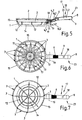
- FIGS. 5 to 7 are not only an above-mentioned annular channel 2 with a plurality of metering orifices 3 or nozzles 3, but advantageously two vertically arranged one above the other annular channels 2 with, for example, a total of 16 nozzles 3 and 16 metering 3.
- the side wall 12 of the ladle body 1 includes this two ring channels 2.
- the two illustrated cow systems or ring channels 2 are arranged in two different planes.
- the metering orifices 3 or nozzles 3 of the two annular channels 2 are also arranged advantageously offset by approximately 22.5 ° to each other (viewed in the circumferential direction).
- the metering orifices 3 or nozzles 3, viewed in the vertical direction can have different metering or outflow directions, i. Inclinations or angles, have, so that the frying oil 13 and the spray jets 13 meet different steeply in the interior or on the frying surface or the pan bottom 14 and thus on the not shown Bratgut.
- the metering orifices 3 and / or nozzles 3 of the lower and / or upper ring conduit 2 can, for example, be made inclined to the ladle bottom 14 so that the sprayed seasoning oil flows along the collecting / drainage channels 12 (cf. FIG. 7 ) can flow to the bottom of the pan 14.
- the brooding aid such as a seasoning oil or the like can thereby additionally act on the fried material from the bottom 12 of the pan.
- the metering orifices 3 or nozzles 3 of the lower and / or upper ring conduit 2 can be differently oriented / inclined with respect to the horizontal plane, so that the brooding agent can act on the fried material in different ways / directions or impact locations, such as a seasoning oil or the like .
- the metering orifices 3 or nozzles 3 of the upper annular channel 2 can be relatively steeply inclined or steeply aligned, for example according to the fourth variant in FIG FIG. 4 ).
- the metering orifices 3 or nozzles 3 of the lower annular channel 2 can be inclined more easily or less strongly, ie, they can be aligned relatively flat.
- the annular channel 2 is formed as a closed, continuous annular channel 2.
- the annular channel 2 is not a closed, continuous ring, but an annular channel, which is not formed completely closed or interrupted in particular on the opposite side of the handle 9. This may for example be advantageous in the case of a distribution of the nozzles 3 over a range of approximately two thirds of the circumference.
- the handle 9 comprises at least one or more memory or a (pressurized) cartridge 7 and / or compressed gas cartridge 16 to the memory of the extinguishing agent and in particular also for storing a Bratangesffens such as frying oil, spice oil or the like provided.
- a single pressurized storage 16 is provided for storing the extinguishing agent, which is preferably under pressure from some bar.
- the operating medium or extinguishing agent and possibly the Bratangeskar by means of an advantageous Dosierknopfes 6 or a metering device which actuates a valve 5 and opens and closes, fed into a feed line 4 and a channel of the handle 9 and be metered.
- the supply line 4 for the Bratangesmittel opens into the annular channel 2 and this in the metering orifices 3 and 3 nozzles of the ladle body first
- the cartridge 7 to a pressurization, so that by pressing the Dosierknopfes 6, the valve 5 is actuated / opened and the resources 13 and extinguishing agent 20 and in particular the Bratangeskar 13 such as oil or the like via the (respective) supply line 4 to Extinguishing nozzle 18 and possibly, for example, flows into the annular channel 2 and in each case via the nozzles 3, 18 (as in FIG. 2 . 4 or 6 illustrated) is sprayed in an advantageous manner in the inner space / inner region of the ladle body 2.
- each two separate memory 7, 16 are provided, wherein a cartridge 7 with resources or extinguishing agent 20 and / or possibly with the Bratangesstoff / Bratöl 13 or spice oil and / or cleaning fluid / agent and also in the handle 9 a compressed gas cartridge 16 is present is.
- FIGS. 4 and 6 illustrate that the Bratipposstoff 13 and the frying oil 13 is relatively large and evenly distributed in the fry body 1 and on the roasting surface 14.
- Bratöl or Bratfett by means of a separate oil bottle or a single Bratfett
- a particularly large-scale or uniform and thus advantageous distribution of Bratöls or Bratosffens is achieved according to the invention.
- the amount that is introduced into the ladle body 1 can be significantly reduced, without this would mean disadvantages for the frying of the food.
- the cartridge 7 or the reservoir 7, 16 in the handle 9 is advantageously an exchangeable cartridge 7 or compressed gas cartridge 16 (cf., replacement cartridge 16.1 according to FIG FIGS. 1 . 3 or 5 ), which can be introduced into the handle 9, for example with the aid of a removable / unscrewable closure button 8 or a screw cap.
- the closure button 8 is for example provided by means of a screw thread, so that the cartridge 7 is securely and firmly fixed, for example, in the region of the valve 5 by screwing the closure button 8 and advantageously sealed.
- the compressed gas cartridge 16 can be replaced, for example, via a separate access, which is provided on the underside of the handle 9.
- the print cartridge 16 is an erase cartridge 16, which comprises a pressurized extinguishing agent, in particular carbon dioxide.
- two separate storage or cartridges 7 can be used in the handle 9 (see. Figures 3 . 5 ), wherein, for example, a (non-pressurized) Bratölkartusche 7.1 is disposed in the immediate region of the valve 5 or Dosierknopfes 6 and preferably in the end region of the handle 9, that is, the portion of the handle 9 of the pan body is disposed opposite, a second cartridge 7, in particular a compressed gas cartridge or compressed gas cartridge 16, are arranged.
- a (non-pressurized) Bratölkartusche 7.1 is disposed in the immediate region of the valve 5 or Dosierknopfes 6 and preferably in the end region of the handle 9, that is, the portion of the handle 9 of the pan body is disposed opposite, a second cartridge 7, in particular a compressed gas cartridge or compressed gas cartridge 16, are arranged.
- the Bratangeskar or frying oil of the (non-pressure) Bratölaires or Bratölkartusche 7.1 with the compressed gas, in particular carbon dioxide or the like, are applied in an advantageous manner when you press the Dosierknopfes 6 or when opening the valve 5 and transported through the distribution system or through the feed line 4 and the annular channel 2 to the nozzles 3 and atomized / distributed. Due to the comparatively high pressure of the compressed gas, the frying oil 13 is advantageously finely distributed by means of the nozzles 3 or sprayed / atomized into the pan body 1.
- a separate or second operation button in particular an emergency button or delete button, are arranged on / in the handle 9, for example, as an extinguishing agent memory sixteenth trained carbon dioxide pressure gas storage 16 and a delete cartridge 7.3 or the compressed gas cartridge 16 in the handle 9 is actuated / activated, so that in the event of fire, a fast and effective deletion is ensured in the pan body 1.
- the extinguishing agent or the carbon dioxide gas are introduced into the ladle body 1, so that the fire is extinguished very quickly and effectively. This increases the reliability of the frying device according to the invention to a considerable extent.
- a temperature sensor 10 which can detect a temperature of the socket body 1 or in / on the interior or the side wall 15 in an advantageous manner.
- the temperature sensor 10 is formed as a bimetallic element, thermal expansion element or the like, so that advantageously an electric power supply / - storage etc. can be omitted for an electrical sensor.
- the temperature sensor 10 causes e.g. at a first temperature, in particular a warning temperature, that a warning signal / warning tone is generated by an acoustic signal generator / signal horn 11.
- compressed gas is preferably fed to the signal transmitter / signal horn 11 by means of the compressed gas cartridge 16, so that the flowing gas generates a signal tone or, if possible, a shrill tone or emits it. This warns a person in an advantageous manner that there is an overheating and / or a fire hazard.
- an erase operation is generated according to the invention.
- extinguishing gas or pressurized gas is preferably used by means of the compressed gas cartridge 16 so that, as already explained above, the gas extinguishes the fire.
- a two-stage Safety concept / system can be realized, namely in a first stage, a warning sound or a warning is realized and in a second stage, a fire is deleted. This leads to an extraordinary and new safety ladle according to the invention.
Landscapes
- Health & Medical Sciences (AREA)
- Public Health (AREA)
- Business, Economics & Management (AREA)
- Emergency Management (AREA)
- Engineering & Computer Science (AREA)
- Food Science & Technology (AREA)
- Frying-Pans Or Fryers (AREA)
- Food-Manufacturing Devices (AREA)
Applications Claiming Priority (1)
| Application Number | Priority Date | Filing Date | Title |
|---|---|---|---|
| DE102018100733.7A DE102018100733A1 (de) | 2018-01-15 | 2018-01-15 | Bratvorrichtung mit einem Handgriff und einem Bratkörper |
Publications (2)
| Publication Number | Publication Date |
|---|---|
| EP3510904A1 true EP3510904A1 (fr) | 2019-07-17 |
| EP3510904B1 EP3510904B1 (fr) | 2020-08-19 |
Family
ID=65003280
Family Applications (1)
| Application Number | Title | Priority Date | Filing Date |
|---|---|---|---|
| EP19150454.7A Active EP3510904B1 (fr) | 2018-01-15 | 2019-01-07 | Dispositif de rôtisserie equippé avec une poignée et un dispositif d'extinction |
Country Status (2)
| Country | Link |
|---|---|
| EP (1) | EP3510904B1 (fr) |
| DE (1) | DE102018100733A1 (fr) |
Families Citing this family (1)
| Publication number | Priority date | Publication date | Assignee | Title |
|---|---|---|---|---|
| KR102943210B1 (ko) | 2023-12-29 | 2026-03-26 | 한영대학교 산학협력단 | 자동 소화기능이 구비된 조리 용기용 탈부착식 손잡이 |
Citations (4)
| Publication number | Priority date | Publication date | Assignee | Title |
|---|---|---|---|---|
| US2204467A (en) | 1938-07-16 | 1940-06-11 | Beatson William | Frying pan |
| EP0766942A1 (fr) | 1995-10-06 | 1997-04-09 | Dong-Gyun Park | Poêle à frire ayant des moyens pour amener de l'huile |
| EP0931496A1 (fr) | 1998-01-23 | 1999-07-28 | Seb S.A. | Ustensile culinaire comprenant un capteur pour mesurer la température de cet ustensile |
| CN207323346U (zh) * | 2017-02-25 | 2018-05-08 | 宁波歌瑞特厨具有限公司 | 煎锅 |
Family Cites Families (1)
| Publication number | Priority date | Publication date | Assignee | Title |
|---|---|---|---|---|
| DE102016115763B4 (de) * | 2016-08-25 | 2023-01-26 | Jürgen Dangel | Bratvorrichtung |
-
2018
- 2018-01-15 DE DE102018100733.7A patent/DE102018100733A1/de not_active Withdrawn
-
2019
- 2019-01-07 EP EP19150454.7A patent/EP3510904B1/fr active Active
Patent Citations (5)
| Publication number | Priority date | Publication date | Assignee | Title |
|---|---|---|---|---|
| US2204467A (en) | 1938-07-16 | 1940-06-11 | Beatson William | Frying pan |
| EP0766942A1 (fr) | 1995-10-06 | 1997-04-09 | Dong-Gyun Park | Poêle à frire ayant des moyens pour amener de l'huile |
| EP0931496A1 (fr) | 1998-01-23 | 1999-07-28 | Seb S.A. | Ustensile culinaire comprenant un capteur pour mesurer la température de cet ustensile |
| DE69907524T2 (de) * | 1998-01-23 | 2003-11-20 | Seb S.A., Ecully | Küchengerät mit einem Temperatursensor zum Messen seiner Temperatur |
| CN207323346U (zh) * | 2017-02-25 | 2018-05-08 | 宁波歌瑞特厨具有限公司 | 煎锅 |
Also Published As
| Publication number | Publication date |
|---|---|
| EP3510904B1 (fr) | 2020-08-19 |
| DE102018100733A1 (de) | 2019-07-18 |
Similar Documents
| Publication | Publication Date | Title |
|---|---|---|
| DE69314181T2 (de) | Grill zur verwendung im freien | |
| DE3027813C2 (de) | Selbstlöschender, oben offener Abfallbehälter, insbesondere Papierkorb | |
| WO1997024052A1 (fr) | Machine a cafe | |
| DE69834289T2 (de) | Feuerunterdrückungssystem | |
| EP3289938B1 (fr) | Poêle pourvue d'une poignée et d'un corps | |
| DE2156328B2 (de) | Geraet zur gesichtspflege mittels dampf | |
| DE102004063278A1 (de) | Vorrichtung und Verfahren zur Erwärmung einer in einem Portionsbehälter befindlichen Speisenportion | |
| EP3510904B1 (fr) | Dispositif de rôtisserie equippé avec une poignée et un dispositif d'extinction | |
| DE102004008129A1 (de) | Grillgerät, insbesondere für gewerbliche Küchen | |
| WO1996022719A1 (fr) | Dispositif permettant de chauffer un liquide potable | |
| DE3830039C2 (de) | Druck-Kochtopf mit einem Überdruckventil | |
| DE2041264A1 (de) | Wiederauffuellbares Geraet,insbesondere Feuerloescher | |
| DE3512370A1 (de) | Dampferzeuger | |
| DE102014014971B4 (de) | Handspritze | |
| WO1981001106A1 (fr) | Dispositif d'extinction pour lutter contre l'incendie d'un recipient de cuisson | |
| AT502472B1 (de) | Vorrichtung zur erzeugung und entnahme von flüssigen oder schaumförmigen lebensmitteln | |
| DE163012C (fr) | ||
| EP0419420A1 (fr) | Distributeur pour combustibles liquides facilement inflammables | |
| EP3118528B1 (fr) | Système de cuisson destiné à la cuisson et l'aromatisation | |
| DE102016122352A1 (de) | Mehrteilige Espresso-Kaffeemaschine | |
| DE3516430A1 (de) | Feuerloescher | |
| DE29905060U1 (de) | Sprüheinrichtung zum Würzen | |
| DE4430291A1 (de) | Vorrichtung zum Verdunsten eines flüssigen Wirkstoffs | |
| DE2744914A1 (de) | Vorrichtung zur verteilung von normalerweise festem, durch hitze verfluessigbarem material | |
| DE102019001223B4 (de) | Sprühgerät |
Legal Events
| Date | Code | Title | Description |
|---|---|---|---|
| PUAI | Public reference made under article 153(3) epc to a published international application that has entered the european phase |
Free format text: ORIGINAL CODE: 0009012 |
|
| STAA | Information on the status of an ep patent application or granted ep patent |
Free format text: STATUS: THE APPLICATION HAS BEEN PUBLISHED |
|
| AK | Designated contracting states |
Kind code of ref document: A1 Designated state(s): AL AT BE BG CH CY CZ DE DK EE ES FI FR GB GR HR HU IE IS IT LI LT LU LV MC MK MT NL NO PL PT RO RS SE SI SK SM TR |
|
| AX | Request for extension of the european patent |
Extension state: BA ME |
|
| STAA | Information on the status of an ep patent application or granted ep patent |
Free format text: STATUS: REQUEST FOR EXAMINATION WAS MADE |
|
| 17P | Request for examination filed |
Effective date: 20200116 |
|
| RBV | Designated contracting states (corrected) |
Designated state(s): AL AT BE BG CH CY CZ DE DK EE ES FI FR GB GR HR HU IE IS IT LI LT LU LV MC MK MT NL NO PL PT RO RS SE SI SK SM TR |
|
| REG | Reference to a national code |
Ref country code: DE Ref legal event code: R079 Ref document number: 502019000144 Country of ref document: DE Free format text: PREVIOUS MAIN CLASS: A47J0037100000 Ipc: A47J0045060000 |
|
| GRAP | Despatch of communication of intention to grant a patent |
Free format text: ORIGINAL CODE: EPIDOSNIGR1 |
|
| STAA | Information on the status of an ep patent application or granted ep patent |
Free format text: STATUS: GRANT OF PATENT IS INTENDED |
|
| RIC1 | Information provided on ipc code assigned before grant |
Ipc: A47J 45/06 20060101AFI20200227BHEP Ipc: A62C 3/00 20060101ALI20200227BHEP Ipc: A62C 13/00 20060101ALI20200227BHEP Ipc: A62C 37/40 20060101ALI20200227BHEP Ipc: A47J 37/10 20060101ALI20200227BHEP |
|
| INTG | Intention to grant announced |
Effective date: 20200331 |
|
| GRAS | Grant fee paid |
Free format text: ORIGINAL CODE: EPIDOSNIGR3 |
|
| GRAA | (expected) grant |
Free format text: ORIGINAL CODE: 0009210 |
|
| STAA | Information on the status of an ep patent application or granted ep patent |
Free format text: STATUS: THE PATENT HAS BEEN GRANTED |
|
| AK | Designated contracting states |
Kind code of ref document: B1 Designated state(s): AL AT BE BG CH CY CZ DE DK EE ES FI FR GB GR HR HU IE IS IT LI LT LU LV MC MK MT NL NO PL PT RO RS SE SI SK SM TR |
|
| REG | Reference to a national code |
Ref country code: CH Ref legal event code: EP |
|
| REG | Reference to a national code |
Ref country code: DE Ref legal event code: R096 Ref document number: 502019000144 Country of ref document: DE |
|
| REG | Reference to a national code |
Ref country code: AT Ref legal event code: REF Ref document number: 1302984 Country of ref document: AT Kind code of ref document: T Effective date: 20200915 |
|
| REG | Reference to a national code |
Ref country code: IE Ref legal event code: FG4D Free format text: LANGUAGE OF EP DOCUMENT: GERMAN |
|
| REG | Reference to a national code |
Ref country code: CH Ref legal event code: NV Representative=s name: DENNEMEYER AG, CH |
|
| REG | Reference to a national code |
Ref country code: LT Ref legal event code: MG4D |
|
| REG | Reference to a national code |
Ref country code: NL Ref legal event code: MP Effective date: 20200819 |
|
| PG25 | Lapsed in a contracting state [announced via postgrant information from national office to epo] |
Ref country code: BG Free format text: LAPSE BECAUSE OF FAILURE TO SUBMIT A TRANSLATION OF THE DESCRIPTION OR TO PAY THE FEE WITHIN THE PRESCRIBED TIME-LIMIT Effective date: 20201119 Ref country code: NO Free format text: LAPSE BECAUSE OF FAILURE TO SUBMIT A TRANSLATION OF THE DESCRIPTION OR TO PAY THE FEE WITHIN THE PRESCRIBED TIME-LIMIT Effective date: 20201119 Ref country code: PT Free format text: LAPSE BECAUSE OF FAILURE TO SUBMIT A TRANSLATION OF THE DESCRIPTION OR TO PAY THE FEE WITHIN THE PRESCRIBED TIME-LIMIT Effective date: 20201221 Ref country code: FI Free format text: LAPSE BECAUSE OF FAILURE TO SUBMIT A TRANSLATION OF THE DESCRIPTION OR TO PAY THE FEE WITHIN THE PRESCRIBED TIME-LIMIT Effective date: 20200819 Ref country code: GR Free format text: LAPSE BECAUSE OF FAILURE TO SUBMIT A TRANSLATION OF THE DESCRIPTION OR TO PAY THE FEE WITHIN THE PRESCRIBED TIME-LIMIT Effective date: 20201120 Ref country code: LT Free format text: LAPSE BECAUSE OF FAILURE TO SUBMIT A TRANSLATION OF THE DESCRIPTION OR TO PAY THE FEE WITHIN THE PRESCRIBED TIME-LIMIT Effective date: 20200819 Ref country code: SE Free format text: LAPSE BECAUSE OF FAILURE TO SUBMIT A TRANSLATION OF THE DESCRIPTION OR TO PAY THE FEE WITHIN THE PRESCRIBED TIME-LIMIT Effective date: 20200819 Ref country code: HR Free format text: LAPSE BECAUSE OF FAILURE TO SUBMIT A TRANSLATION OF THE DESCRIPTION OR TO PAY THE FEE WITHIN THE PRESCRIBED TIME-LIMIT Effective date: 20200819 |
|
| PG25 | Lapsed in a contracting state [announced via postgrant information from national office to epo] |
Ref country code: LV Free format text: LAPSE BECAUSE OF FAILURE TO SUBMIT A TRANSLATION OF THE DESCRIPTION OR TO PAY THE FEE WITHIN THE PRESCRIBED TIME-LIMIT Effective date: 20200819 Ref country code: PL Free format text: LAPSE BECAUSE OF FAILURE TO SUBMIT A TRANSLATION OF THE DESCRIPTION OR TO PAY THE FEE WITHIN THE PRESCRIBED TIME-LIMIT Effective date: 20200819 Ref country code: NL Free format text: LAPSE BECAUSE OF FAILURE TO SUBMIT A TRANSLATION OF THE DESCRIPTION OR TO PAY THE FEE WITHIN THE PRESCRIBED TIME-LIMIT Effective date: 20200819 Ref country code: RS Free format text: LAPSE BECAUSE OF FAILURE TO SUBMIT A TRANSLATION OF THE DESCRIPTION OR TO PAY THE FEE WITHIN THE PRESCRIBED TIME-LIMIT Effective date: 20200819 Ref country code: IS Free format text: LAPSE BECAUSE OF FAILURE TO SUBMIT A TRANSLATION OF THE DESCRIPTION OR TO PAY THE FEE WITHIN THE PRESCRIBED TIME-LIMIT Effective date: 20201219 |
|
| PG25 | Lapsed in a contracting state [announced via postgrant information from national office to epo] |
Ref country code: SM Free format text: LAPSE BECAUSE OF FAILURE TO SUBMIT A TRANSLATION OF THE DESCRIPTION OR TO PAY THE FEE WITHIN THE PRESCRIBED TIME-LIMIT Effective date: 20200819 Ref country code: RO Free format text: LAPSE BECAUSE OF FAILURE TO SUBMIT A TRANSLATION OF THE DESCRIPTION OR TO PAY THE FEE WITHIN THE PRESCRIBED TIME-LIMIT Effective date: 20200819 Ref country code: CZ Free format text: LAPSE BECAUSE OF FAILURE TO SUBMIT A TRANSLATION OF THE DESCRIPTION OR TO PAY THE FEE WITHIN THE PRESCRIBED TIME-LIMIT Effective date: 20200819 Ref country code: DK Free format text: LAPSE BECAUSE OF FAILURE TO SUBMIT A TRANSLATION OF THE DESCRIPTION OR TO PAY THE FEE WITHIN THE PRESCRIBED TIME-LIMIT Effective date: 20200819 Ref country code: EE Free format text: LAPSE BECAUSE OF FAILURE TO SUBMIT A TRANSLATION OF THE DESCRIPTION OR TO PAY THE FEE WITHIN THE PRESCRIBED TIME-LIMIT Effective date: 20200819 |
|
| REG | Reference to a national code |
Ref country code: DE Ref legal event code: R097 Ref document number: 502019000144 Country of ref document: DE |
|
| PG25 | Lapsed in a contracting state [announced via postgrant information from national office to epo] |
Ref country code: AL Free format text: LAPSE BECAUSE OF FAILURE TO SUBMIT A TRANSLATION OF THE DESCRIPTION OR TO PAY THE FEE WITHIN THE PRESCRIBED TIME-LIMIT Effective date: 20200819 Ref country code: ES Free format text: LAPSE BECAUSE OF FAILURE TO SUBMIT A TRANSLATION OF THE DESCRIPTION OR TO PAY THE FEE WITHIN THE PRESCRIBED TIME-LIMIT Effective date: 20200819 |
|
| PLBE | No opposition filed within time limit |
Free format text: ORIGINAL CODE: 0009261 |
|
| STAA | Information on the status of an ep patent application or granted ep patent |
Free format text: STATUS: NO OPPOSITION FILED WITHIN TIME LIMIT |
|
| PG25 | Lapsed in a contracting state [announced via postgrant information from national office to epo] |
Ref country code: SK Free format text: LAPSE BECAUSE OF FAILURE TO SUBMIT A TRANSLATION OF THE DESCRIPTION OR TO PAY THE FEE WITHIN THE PRESCRIBED TIME-LIMIT Effective date: 20200819 |
|
| 26N | No opposition filed |
Effective date: 20210520 |
|
| PG25 | Lapsed in a contracting state [announced via postgrant information from national office to epo] |
Ref country code: IT Free format text: LAPSE BECAUSE OF FAILURE TO SUBMIT A TRANSLATION OF THE DESCRIPTION OR TO PAY THE FEE WITHIN THE PRESCRIBED TIME-LIMIT Effective date: 20200819 |
|
| PG25 | Lapsed in a contracting state [announced via postgrant information from national office to epo] |
Ref country code: SI Free format text: LAPSE BECAUSE OF FAILURE TO SUBMIT A TRANSLATION OF THE DESCRIPTION OR TO PAY THE FEE WITHIN THE PRESCRIBED TIME-LIMIT Effective date: 20200819 Ref country code: MC Free format text: LAPSE BECAUSE OF FAILURE TO SUBMIT A TRANSLATION OF THE DESCRIPTION OR TO PAY THE FEE WITHIN THE PRESCRIBED TIME-LIMIT Effective date: 20200819 |
|
| PG25 | Lapsed in a contracting state [announced via postgrant information from national office to epo] |
Ref country code: LU Free format text: LAPSE BECAUSE OF NON-PAYMENT OF DUE FEES Effective date: 20210107 |
|
| REG | Reference to a national code |
Ref country code: BE Ref legal event code: MM Effective date: 20210131 |
|
| PG25 | Lapsed in a contracting state [announced via postgrant information from national office to epo] |
Ref country code: FR Free format text: LAPSE BECAUSE OF NON-PAYMENT OF DUE FEES Effective date: 20210131 |
|
| PG25 | Lapsed in a contracting state [announced via postgrant information from national office to epo] |
Ref country code: IE Free format text: LAPSE BECAUSE OF NON-PAYMENT OF DUE FEES Effective date: 20210107 |
|
| PG25 | Lapsed in a contracting state [announced via postgrant information from national office to epo] |
Ref country code: BE Free format text: LAPSE BECAUSE OF NON-PAYMENT OF DUE FEES Effective date: 20210131 |
|
| PGFP | Annual fee paid to national office [announced via postgrant information from national office to epo] |
Ref country code: CH Payment date: 20230130 Year of fee payment: 5 |
|
| PG25 | Lapsed in a contracting state [announced via postgrant information from national office to epo] |
Ref country code: CY Free format text: LAPSE BECAUSE OF FAILURE TO SUBMIT A TRANSLATION OF THE DESCRIPTION OR TO PAY THE FEE WITHIN THE PRESCRIBED TIME-LIMIT Effective date: 20200819 |
|
| PG25 | Lapsed in a contracting state [announced via postgrant information from national office to epo] |
Ref country code: HU Free format text: LAPSE BECAUSE OF FAILURE TO SUBMIT A TRANSLATION OF THE DESCRIPTION OR TO PAY THE FEE WITHIN THE PRESCRIBED TIME-LIMIT; INVALID AB INITIO Effective date: 20190107 |
|
| GBPC | Gb: european patent ceased through non-payment of renewal fee |
Effective date: 20230107 |
|
| PG25 | Lapsed in a contracting state [announced via postgrant information from national office to epo] |
Ref country code: GB Free format text: LAPSE BECAUSE OF NON-PAYMENT OF DUE FEES Effective date: 20230107 |
|
| PG25 | Lapsed in a contracting state [announced via postgrant information from national office to epo] |
Ref country code: MK Free format text: LAPSE BECAUSE OF FAILURE TO SUBMIT A TRANSLATION OF THE DESCRIPTION OR TO PAY THE FEE WITHIN THE PRESCRIBED TIME-LIMIT Effective date: 20200819 |
|
| REG | Reference to a national code |
Ref country code: CH Ref legal event code: PL |
|
| PG25 | Lapsed in a contracting state [announced via postgrant information from national office to epo] |
Ref country code: MT Free format text: LAPSE BECAUSE OF FAILURE TO SUBMIT A TRANSLATION OF THE DESCRIPTION OR TO PAY THE FEE WITHIN THE PRESCRIBED TIME-LIMIT Effective date: 20200819 |
|
| PG25 | Lapsed in a contracting state [announced via postgrant information from national office to epo] |
Ref country code: CH Free format text: LAPSE BECAUSE OF NON-PAYMENT OF DUE FEES Effective date: 20240131 |
|
| PG25 | Lapsed in a contracting state [announced via postgrant information from national office to epo] |
Ref country code: CH Free format text: LAPSE BECAUSE OF NON-PAYMENT OF DUE FEES Effective date: 20240131 |
|
| REG | Reference to a national code |
Ref country code: DE Ref legal event code: R082 Ref document number: 502019000144 Country of ref document: DE Representative=s name: RAVENSPAT PATENTANWAELTE PARTNERSCHAFT MBB, DE |
|
| REG | Reference to a national code |
Ref country code: AT Ref legal event code: MM01 Ref document number: 1302984 Country of ref document: AT Kind code of ref document: T Effective date: 20240107 |
|
| PG25 | Lapsed in a contracting state [announced via postgrant information from national office to epo] |
Ref country code: AT Free format text: LAPSE BECAUSE OF NON-PAYMENT OF DUE FEES Effective date: 20240107 |
|
| PG25 | Lapsed in a contracting state [announced via postgrant information from national office to epo] |
Ref country code: TR Free format text: LAPSE BECAUSE OF FAILURE TO SUBMIT A TRANSLATION OF THE DESCRIPTION OR TO PAY THE FEE WITHIN THE PRESCRIBED TIME-LIMIT Effective date: 20200819 |
|
| PGFP | Annual fee paid to national office [announced via postgrant information from national office to epo] |
Ref country code: DE Payment date: 20260120 Year of fee payment: 8 |
|
| PGFP | Annual fee paid to national office [announced via postgrant information from national office to epo] |
Ref country code: AT Payment date: 20260410 Year of fee payment: 5 |