EP3510908B1 - Accessoire pour tête d'aspiration d'aspirateur permettant de collecter des débris de grande taille - Google Patents
Accessoire pour tête d'aspiration d'aspirateur permettant de collecter des débris de grande taille Download PDFInfo
- Publication number
- EP3510908B1 EP3510908B1 EP18211206.0A EP18211206A EP3510908B1 EP 3510908 B1 EP3510908 B1 EP 3510908B1 EP 18211206 A EP18211206 A EP 18211206A EP 3510908 B1 EP3510908 B1 EP 3510908B1
- Authority
- EP
- European Patent Office
- Prior art keywords
- accessory
- suction head
- base plate
- suction
- vacuumed
- Prior art date
- Legal status (The legal status is an assumption and is not a legal conclusion. Google has not performed a legal analysis and makes no representation as to the accuracy of the status listed.)
- Active
Links
Images


Classifications
-
- A—HUMAN NECESSITIES
- A47—FURNITURE; DOMESTIC ARTICLES OR APPLIANCES; COFFEE MILLS; SPICE MILLS; SUCTION CLEANERS IN GENERAL
- A47L—DOMESTIC WASHING OR CLEANING; SUCTION CLEANERS IN GENERAL
- A47L9/00—Details or accessories of suction cleaners, e.g. mechanical means for controlling the suction or for effecting pulsating action; Storing devices specially adapted to suction cleaners or parts thereof; Carrying-vehicles specially adapted for suction cleaners
- A47L9/02—Nozzles
- A47L9/06—Nozzles with fixed, e.g. adjustably fixed brushes or the like
- A47L9/0673—Nozzles with fixed, e.g. adjustably fixed brushes or the like with removable brushes, combs, lips or pads
-
- A—HUMAN NECESSITIES
- A47—FURNITURE; DOMESTIC ARTICLES OR APPLIANCES; COFFEE MILLS; SPICE MILLS; SUCTION CLEANERS IN GENERAL
- A47L—DOMESTIC WASHING OR CLEANING; SUCTION CLEANERS IN GENERAL
- A47L9/00—Details or accessories of suction cleaners, e.g. mechanical means for controlling the suction or for effecting pulsating action; Storing devices specially adapted to suction cleaners or parts thereof; Carrying-vehicles specially adapted for suction cleaners
- A47L9/02—Nozzles
-
- A—HUMAN NECESSITIES
- A47—FURNITURE; DOMESTIC ARTICLES OR APPLIANCES; COFFEE MILLS; SPICE MILLS; SUCTION CLEANERS IN GENERAL
- A47L—DOMESTIC WASHING OR CLEANING; SUCTION CLEANERS IN GENERAL
- A47L9/00—Details or accessories of suction cleaners, e.g. mechanical means for controlling the suction or for effecting pulsating action; Storing devices specially adapted to suction cleaners or parts thereof; Carrying-vehicles specially adapted for suction cleaners
- A47L9/009—Carrying-vehicles; Arrangements of trollies or wheels; Means for avoiding mechanical obstacles
Definitions
- the present invention relates to the sector of electric household appliances for performing cleaning by means of suction, such as a vacuum cleaner, an electric broom or a multi-purpose vacuum cleaner drum, for sucking up dust and/or fluids and/or debris from a surface. More particularly, it relates to an accessory for a suction head to be fitted to such an electric household appliance configured to vacuum large-size debris from a surface. It also relates to a suction head with an accessory mounted removably thereon.
- suction such as a vacuum cleaner, an electric broom or a multi-purpose vacuum cleaner drum
- large debris For the purposes of the present invention, the expression “large debris”, “large-size body” or “large-size material” (or similar expressions) is understood as meaning a body with a size generally larger than that of a particle of dust or a grain of sand.
- a large-size body may be a grain of rice, a lentil, a bread crumb, a paper clip, a metal staple of a stapler, a piece of cardboard, a fragment of glass or ceramic, a piece of a toy (such as Lego® nanoblock), etc.
- a large-size body may also be an assembly of bodies which are same as each other or different from each other. For example a tuft of animal and/or human hair and/or dust.
- the relevant dimension for classifying a body as large-size debris for the purposes of the present invention is the height of the body when located on the surface to be vacuumed. This relevant dimension is therefore not necessarily the maximum dimension of the said body.
- the relevant dimension of an elongate body (such as a grain of rice) is the diameter in its central part and not the total length of the grain.
- the relevant dimension is essentially the diameter of the wire or in any case the thickness of the staple when it is lying on a surface to be cleaned.
- a large-size body has a relevant dimension greater than or equal to 1 mm.
- the relevant dimension is greater than or equal to 2 mm.
- the relevant dimension is not greater than 5 mm, more preferably not greater than 4 mm.
- a vacuum cleaner, an electric broom or a similar electric household appliance for performing cleaning by means of suction comprises a suction head for sucking up dust, debris or fluids from a surface.
- a suction head is generally referred to by the term "brush”.
- the terms “suction head” and “brush” are considered to be equivalent.
- the term “vacuum cleaner” will be used with a broad meaning so as to include all those apparatus, for professional or domestic use, which perform cleaning by means of suction. Therefore, the term “vacuum cleaner” will comprise a vacuum cleaner, an electric broom, a so-called multi-purpose vacuum cleaner drum, a centralized suction system for domestic or industrial use and a steam supply and suction apparatus.
- a known suction head comprises a base plate shaped so as to have at least one base plate channel open towards a surface to be vacuumed, a suction channel which, during use, is joined to the base plate and is in fluid communication with the base plate channel and optionally a covering body which can be connected to the base plate-suction channel assembly.
- the other end of the suction channel communicates with a suction tube usually via a rotatable joint.
- Suction heads are also known in which the suction channel, during use, is formed together with the covering body.
- US 2005/262662 A1 discloses a suction nozzle for vacuum cleaner or the like with detachable suction duct.
- US 5 502 873 A discloses a pet grooming device.
- GB 2 486 563 A discloses a suction nozzle with shutting plate and converging debris paths.
- US 3 820 189 A discloses a brush adaptor for vacuuming.
- the problem is that generally a vacuum cleaner is designed to clean both hard surfaces and also carpets, rugs, mats, doormats or other pile surfaces.
- a conventional suction head supplied with a vacuum cleaner generally represents a compromise in terms of suction efficiency on the various types of surface.
- the Applicant has defined the object of improving substantially the suction efficiency of a conventional suction head as regards the suction of large-size debris, in particular (but not only) on substantially smooth and compact surfaces, without modifying substantially the suction characteristics of the suction head on other types of surfaces.
- an accessory according to independent claim 1 and which can be removably coupled with a suction head comprising a main body with a top face configured to be coupled with the suction head and a lower face directed towards the surface to be vacuumed when in use.
- the main body has a transverse elongated slot configured to be situated opposite the mouth of the base plate channel of the suction head.
- the accessory also comprises a spacer member for spacing, during use, the lower face from the surface to be vacuumed.
- the spacer member may comprise one or more ribs. As an alternative to or in combination with the ribs, downwardly projecting roller wheels may be provided.
- the present invention provides an accessory for a suction head for a vacuum cleaner, the accessory comprising engaging means configured for removably connecting the accessory to the suction head along its base plate, wherein said accessory comprises a main body having a lower face which, during use, is directed towards the surface to be vacuumed, and a top face comprising said engaging means, wherein said main body comprises a transverse slot configured to be situated opposite the mouth of a channel of the base plate of the suction head when said accessory is connected to said suction head; and wherein said main body comprises spacer members for spacing, during use, the lower face of said main body with respect to the surface to be vacuumed.
- the spacer members comprise a longitudinal rib system and possibly a wheel system.
- the longitudinal rib system comprises a plurality of front longitudinal ribs, upstream of said transverse slot, and a plurality of rear longitudinal ribs, downstream of said transverse slot.
- the longitudinal rib system may also advantageously comprise two lateral edges along the two lateral sides of the accessory.
- the wheel system may comprise four wheels arranged within the general contour of the accessory or arranged outside the general contour of the accessory.
- additional transverse elements may also be present upstream and downstream of the transverse slot.
- the additional transverse elements may be movable from a retracted non-protruding position to an extended position protruding towards the surface to be vacuumed.
- the additional transverse elements may be rubber or similar bristled members.
- the present invention provides a suction head for a vacuum cleaner, the suction head comprising a base plate shaped so as to have at least one base plate channel open towards a surface to be vacuumed, a suction channel which, during use, is joined to the base plate and is in fluid communication with the base plate channel and, optionally, a covering body which is connected to the base plate and/or to the suction channel, further comprising an accessory as said above mounted to said suction head in a removable manner.
- the accessory is preferably mounted, in a removable manner, to the base plate of the suction head.
- the various figures show by way of example a number of embodiments of an accessory for a suction head of a vacuum cleaner or the like.
- the accessory is configured to cooperate with a suction head in order to improve the suction performance on substantially smooth and compact surfaces such as floors consisting of stone (marble or similar), terracotta, clinker, cement, resin, tiles, parquet or the like.
- the accessory is configured to vacuum large-size debris.
- the accessory is configured to be engaged with a suction head, preferably in a removable manner. According to an embodiment of the invention, the accessory is configured to be removably coupled with the base plate of a suction head.
- a suction head 1 comprises a base plate 11 shaped so as to have at least one base plate channel 12 open towards a surface to be vacuumed, a suction channel which, during use, is joined to the base plate 11 and is in fluid communication with the base plate channel 12 and optionally a covering body 15 which can be connected to the base plate 11 and/or to the suction channel.
- the other end of the suction channel communicates with a suction tube, usually via a rotatable joint.
- the suction head 1 is used without the accessory mounted.
- the suction head 1 is complete also with the base plate 11 and may be used without the accessory.
- the accessory is mounted on the suction head (in particular on its base plate 11) when there is a need to vacuum large-size debris.
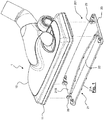
- FIG. 1 By way of example, five embodiments of the accessory to be mounted on a suction head 1 are illustrated and described.
- the first embodiment (identified by the reference number 201) is shown with reference to Figures 1-4 .
- Figures 5-8 show instead the four other embodiments (identified by the reference numbers 202, 203, 204 and 205).
- the same reference numbers will be used to indicate the same components or functionally equivalent components.
- the accessory 201 comprises a substantially flat main body 21 having a shape and dimensions substantially corresponding to those of the base plate 11 of the suction head 1 on which the accessory 201 will be mounted.
- the main body 21 has a lower face 21A directed towards the surface to be vacuumed and an opposite top face 21B.
- the top face 21B is configured so as to have engaging members 29 for engaging in a removable manner with the suction head 1, typically the base plate 11 of the suction head 1.
- the engaging members 29 may comprise partially deformable pins with a wider head which are able to engage inside respective recesses (not shown) in the base plate of the suction head 1.
- Velcro® strips or another functionally equivalent system may be provided.
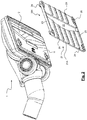
- the base plate 11 of the suction head 1 is shown in Figure 2 .
- This figure also shows the base plate channel 12, the surface around said channel (which often is decisive for the vacuuming performance), and the two seats for strips of velvet.
- the accessory 201 has a substantially rectangular shape and has a transverse slot 22.
- the transverse slot 22 has a form and a size and is positioned so as to be situated in correspondence with the mouth of the base plate channel 12 of the suction head on which the accessory 201 has to be mounted.
- the lower face 21A directed towards the surface to be vacuumed is substantially smooth.
- edges 23 which extend downwards are provided on the two sides of the main body 21.
- the ends of the edges 23 are configured to make contact with (or lightly touch) the surface to be vacuumed.
- the lower face 21A is located at a distance from the surface to be vacuumed equal to the height of the edges 23.
- a longitudinal rib 24 which extends downwards substantially over a distance equal to that of the edges is provided in front of and/or at the rear of the transverse slot 22.
- a plurality of longitudinal ribs 24 are provided both in front of and behind the transverse slot 22.
- These longitudinal ribs 24 provide the main body with rigidity and define further contact lines for distributing the pressure exerted so that the pressure is not concentrated in one point.
- the longitudinal ribs 24 also define tunnels for conveying the large debris the base plate 11.
- the front longitudinal ribs extend towards the transverse slot 22 and therefore towards the channel 12 of substantially from the front edge of the accessory 201 to the front edge of the transverse slot 22.
- the back longitudinal ribs extend substantially from the rear edge of the transverse slot 22 to the rear edge of the accessory 201.
- Each rib can be continuous or discontinuous, namely with gaps.
- the number of longitudinal ribs 24 may consist of any number greater than 2. In any case, the Applicant has noted that ribs which are too close together create tunnels which are too narrow and which could become clogged up with large debris. According to embodiments, the longitudinal ribs 24 may advantageously be 4 or 5 in number. The number of ribs may be the same both at the front and at the rear, but may also be different. For example, there may be four front ribs and five rear ribs. This also due to the fact that the rear surface is typically bigger than the front surface and therefore is weaker.
- the height of the longitudinal ribs 24 depends on the dimensions of the debris to be vacuumed. Preferably, the height of the longitudinal ribs 24 is greater than 2 mm. More preferably it is greater than 3 mm. Preferably, the height of the longitudinal ribs 24 is smaller than 5 mm. More preferably, the height of the ribs 4 is smaller than 4 mm.
- the accessory comprises wheels 25 for favouring the movement of the accessory 201 (when mounted on a suction head) over the surface to be vacuumed.
- the wheels 25 are situated inside the contour of the accessory 201.
- the wheels 25 may be two, three or four in number (as shown in the embodiment).
- the configuration with four wheels, each in the vicinity of a corner of the accessory 201, is that preferred for reasons of stability and efficiency.
- the accessory 201 according to the first embodiment may be made of any material, but preferably is made of a thermoplastic material. This material is advantageous since it is sufficiently soft not to damage the surface to be vacuumed and, at the same time, is sufficiently rigid to withstand impacts or in any case not be subject to deformation with time.
- the accessory 201 may be sold together with the vacuum cleaner so as to increase its versatility and efficiency, also for the vacuuming of large-size debris.
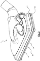
- the accessory 202 according to the second embodiment is shown, coupled with a suction head 1, in Figure 5 .
- the accessory 202 according to the second embodiment is similar to that of the first embodiment and therefore a detailed description will not be repeated.
- the main difference lies in the fact that the wheels 25 are situated on the outside of the contour of the accessory 202.
- This configuration makes the accessory 202 (and therefore the entire suction head) more stable.
- the accessory 202 is lower and therefore less bulky than that of the first embodiment.
- the accessory 203 according to the third embodiment is not part of the present invention and is shown, coupled with a suction head 1, in Figure 6 .
- the accessory 203 according to the third embodiment is similar to that of the first embodiment and therefore a detailed description will not be repeated.
- the main difference lies in the fact that there are no longitudinal ribs 24 and the lower face 21A of the main body 21 takes the form of a substantially smooth surface.
- This configuration makes the accessory 203 (and therefore the entire suction head) lighter. Moreover, the accessory is able to suck up also relatively large debris, without the risk of this debris getting stuck between one rib and another.
- the accessory 204 according to the fourth embodiment is shown, coupled with a suction head 1, in Figure 7 .
- the accessory 204 according to the fourth embodiment is similar to that of the first embodiment and therefore a detailed description will not be repeated.
- the main difference lies in the fact that there are no wheels.
- the accessory is therefore configured to make sliding contact (via the ribs 24) with the surface to be vacuumed.
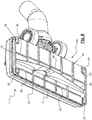
- the accessory 205 according to the fifth embodiment is shown, coupled with a suction head 1, in Figure 8 .
- the accessory 205 according to the fifth embodiment is similar to that of the first embodiment and therefore a detailed description will not be repeated.
- the main difference lies in the fact that additional transverse elements 26 are provided.
- additional front or rear transverse elements 26 with respect to the transverse slot 22 are provided.
- additional front and rear transverse elements 26 with respect to the transverse slot 22 are provided.
- the additional transverse elements 26 may be aligned with each other (such as the front elements in Figure 8 ) or not aligned with each other (such as the rear elements in Figure 8 ).
- the additional transverse elements 26 may be fixed or, preferably, movable. In the embodiment with movable transverse elements, these transverse elements are movable between a first position which is inset, i.e. not projecting from the lower face 21A of the main body, and a projecting position, such as that shown in Figure 8 .
- the system for retracting or extracting the additional transverse elements 26 may be similar to the known systems for lowering or raising a bristled or rubber insert, by means of operation of a pushbutton.
- the additional transverse elements 26 may be in the form of bristled, natural rubber or thermoplastic rubber bars, and could be extruded or co-moulded profiles.
- the additional transverse elements are configured to remain in the lowered position during suction of the small-size or medium-size debris and to be retracted when it is required to suck up large-size debris, thus freeing the space between the ribs. In this way, the suction efficiency is greater when there are no large debris to be vacuumed, but the same accessory also allows the vacuuming of large debris. Therefore, with the accessory according to the invention it is possible to suck up the fragments of a broken sugar bowl which has fallen onto the floor and the sugar originally contained inside the bowl.
- the longitudinal ribs 24 may be straight and directed in the longitudinal direction or may be inclined with respect to the longitudinal direction. They may also not have rectilinear progression, but instead have a sinusoidal or similar progression.
Landscapes
- Engineering & Computer Science (AREA)
- Mechanical Engineering (AREA)
- Nozzles For Electric Vacuum Cleaners (AREA)
Claims (10)
- Accessoire (201, 202, 203, 204, 205) pour une tête d'aspiration (1) pour un aspirateur, ledit accessoire (201-205) comprenant des moyens de mise en prise (29) configurés pour raccorder, de manière amovible, ledit accessoire à ladite tête d'aspiration (1) au niveau de sa plaque de base (11),
dans lequel ledit accessoire (201-205) comprend un corps principal (21) ayant une face inférieure (21A) qui, pendant l'utilisation, est dirigée vers la surface à aspirer, et une face supérieure (21B) comprenant lesdits moyens de mise en prise (29),
dans lequel ledit corps principal (21) comprend une fente transversale (22) configurée pour être située en correspondance de la bouche d'un canal (12) de la plaque de base (11) de la tête d'aspiration (1) lorsque ledit accessoire (201-205) est raccordé à ladite tête d'aspiration (1) ;
dans lequel ledit corps principal (21) comprend des éléments d'espacement (23, 24, 25) pour espacer, pendant l'utilisation, la face inférieure (21A) dudit corps principal (21) par rapport à la surface à aspirer ; et
dans lequel lesdits éléments d'espacement (23, 24, 25) comprennent un système de nervures longitudinales (23, 24) comprenant une pluralité de nervures longitudinales avant (24) en amont de ladite fente transversale (22) et une pluralité de nervures longitudinales arrière (24) en aval de ladite fente transversale (22) formant des tunnels. - Accessoire (201-205) selon la revendication 1, dans lequel ledit système de nervures longitudinales (23, 24) comprend des bords latéraux (23) le long des côtés latéraux de l'accessoire (201-205).
- Accessoire (201-205) selon les revendications 1 ou 2, dans lequel lesdits éléments d'espacement (23, 24, 25) comprennent un système de roues (25).
- Accessoire (201-205) selon la revendication 3, dans lequel ledit système de roues (25) comprend quatre roues (25) agencées dans le contour général de l'accessoire (201-205).
- Accessoire (201-205) selon la revendication 3 ou 4, dans lequel ledit système de roues (25) comprend quatre roues (25) agencées à l'extérieur du contour général de l'accessoire (201-205).
- Accessoire (201-205) selon l'une quelconque des revendications précédentes, comprenant en outre des éléments transversaux (26) supplémentaires en amont et en aval de ladite fente transversale (22).
- Accessoire (201-205) selon la revendication 6, dans lequel lesdits éléments transversaux (26) supplémentaires sont mobiles d'une position sans saillie rétractée à une position étendue faisant saillie vers la surface à aspirer.
- Accessoire (201-205) selon la revendication 6 ou 7, dans lequel lesdits éléments transversaux (26) supplémentaires comprennent des éléments en caoutchouc ou à poils similaires.
- Tête d'aspiration (1) pour un aspirateur, la tête d'aspiration (1) comprenant une plaque de base (11) formée pour avoir au moins un canal de plaque de base (12) ouvert vers une surface à aspirer, un canal d'aspiration qui, pendant l'utilisation, est assemblé à la plaque de base (11) et est en communication de fluide avec le canal de plaque de base (12) et un corps de recouvrement (15) qui est raccordé à la plaque de base (11) et/ou au canal d'aspiration, comprenant en outre un accessoire (201-205) selon l'une quelconque des revendications précédentes, montés sur ladite tête d'aspiration d'une manière amovible.
- Tête d'aspiration (1) selon la revendication 9, dans lequel ledit accessoire (201-205) est monté sur la plaque de base (11) de la tête d'aspiration (1).
Priority Applications (1)
| Application Number | Priority Date | Filing Date | Title |
|---|---|---|---|
| PL18211206T PL3510908T3 (pl) | 2017-12-11 | 2018-12-10 | Element wyposażenia do odkurzacza głowica ssąca do zbierania dużego brudu |
Applications Claiming Priority (1)
| Application Number | Priority Date | Filing Date | Title |
|---|---|---|---|
| IT201700142380 | 2017-12-11 |
Publications (2)
| Publication Number | Publication Date |
|---|---|
| EP3510908A1 EP3510908A1 (fr) | 2019-07-17 |
| EP3510908B1 true EP3510908B1 (fr) | 2020-07-22 |
Family
ID=61731746
Family Applications (1)
| Application Number | Title | Priority Date | Filing Date |
|---|---|---|---|
| EP18211206.0A Active EP3510908B1 (fr) | 2017-12-11 | 2018-12-10 | Accessoire pour tête d'aspiration d'aspirateur permettant de collecter des débris de grande taille |
Country Status (7)
| Country | Link |
|---|---|
| US (1) | US20190174983A1 (fr) |
| EP (1) | EP3510908B1 (fr) |
| CN (1) | CN109893031B (fr) |
| DK (1) | DK3510908T3 (fr) |
| ES (1) | ES2827209T3 (fr) |
| HU (1) | HUE051529T2 (fr) |
| PL (1) | PL3510908T3 (fr) |
Families Citing this family (10)
| Publication number | Priority date | Publication date | Assignee | Title |
|---|---|---|---|---|
| US11224319B2 (en) | 2017-12-11 | 2022-01-18 | New Ermes Europe S.R.L. | Base plate for a vacuum cleaner suction head for the suction of fine dust and large debris |
| JP1641037S (fr) | 2018-09-18 | 2019-09-09 | ||
| DE102019117777A1 (de) * | 2019-07-02 | 2021-01-07 | Miele & Cie. Kg | Gleitsohle, Staubsaugerdüse und Staubsauger |
| IT202000001555A1 (it) | 2020-01-28 | 2021-07-28 | New Ermes Europe Srl | Dispositivo adattatore per aspirapolvere elettrico senza filo |
| USD953673S1 (en) | 2020-02-17 | 2022-05-31 | New Ermes Europe S.R.L. | Head of a vacuum cleaner |
| CN116634912A (zh) | 2020-12-23 | 2023-08-22 | 新埃莫斯欧洲有限责任公司 | 电动抽吸头 |
| CN113040644B (zh) * | 2021-03-31 | 2023-04-14 | 北京顺造科技有限公司 | 吸尘器地刷及吸尘器 |
| USD1028403S1 (en) * | 2021-11-22 | 2024-05-21 | Project S, Inc. | Vacuum floorhead |
| JP1763025S (ja) * | 2022-02-23 | 2024-02-06 | 掃除機ヘッド | |
| JP1763027S (ja) * | 2022-02-23 | 2024-02-06 | 掃除機ヘッド |
Citations (2)
| Publication number | Priority date | Publication date | Assignee | Title |
|---|---|---|---|---|
| EP3326504A1 (fr) * | 2016-11-23 | 2018-05-30 | Seb S.A. | Accessoire anti-blocage pour aspiration de tapis ou moquette adaptable sur une tete de succion d aspirateur |
| EP3345523A1 (fr) * | 2017-01-10 | 2018-07-11 | Miele & Cie. KG | Buse de sol pour aspirateur et aspirateur |
Family Cites Families (6)
| Publication number | Priority date | Publication date | Assignee | Title |
|---|---|---|---|---|
| SE7312670L (fr) * | 1972-11-22 | 1975-03-19 | Electrolux Ab | |
| US3820189A (en) * | 1972-12-11 | 1974-06-28 | E Roth | Brush adaptor for vacuuming |
| US4777696A (en) * | 1986-07-17 | 1988-10-18 | The Regina Co., Inc. | Vacuum cleaner nozzle |
| US5502873A (en) * | 1994-04-05 | 1996-04-02 | Hogan; Marianne | Pet grooming device |
| ITMI20041074A1 (it) * | 2004-05-28 | 2004-08-28 | New Ermes Europe Spa | Testa di aspirazione per spirapolvere o simile con condotto di aspirazione separabile |
| AU2011253852B2 (en) * | 2010-12-15 | 2014-06-05 | Bissell Inc. | Suction nozzle with shuttling plate and converging debris paths |
-
2018
- 2018-12-06 US US16/211,449 patent/US20190174983A1/en not_active Abandoned
- 2018-12-10 PL PL18211206T patent/PL3510908T3/pl unknown
- 2018-12-10 ES ES18211206T patent/ES2827209T3/es active Active
- 2018-12-10 DK DK18211206.0T patent/DK3510908T3/da active
- 2018-12-10 EP EP18211206.0A patent/EP3510908B1/fr active Active
- 2018-12-10 HU HUE18211206A patent/HUE051529T2/hu unknown
- 2018-12-11 CN CN201811506976.0A patent/CN109893031B/zh active Active
Patent Citations (2)
| Publication number | Priority date | Publication date | Assignee | Title |
|---|---|---|---|---|
| EP3326504A1 (fr) * | 2016-11-23 | 2018-05-30 | Seb S.A. | Accessoire anti-blocage pour aspiration de tapis ou moquette adaptable sur une tete de succion d aspirateur |
| EP3345523A1 (fr) * | 2017-01-10 | 2018-07-11 | Miele & Cie. KG | Buse de sol pour aspirateur et aspirateur |
Also Published As
| Publication number | Publication date |
|---|---|
| DK3510908T3 (da) | 2020-10-12 |
| EP3510908A1 (fr) | 2019-07-17 |
| ES2827209T3 (es) | 2021-05-20 |
| CN109893031A (zh) | 2019-06-18 |
| US20190174983A1 (en) | 2019-06-13 |
| HUE051529T2 (hu) | 2021-03-01 |
| CN109893031B (zh) | 2022-05-10 |
| PL3510908T3 (pl) | 2021-02-08 |
Similar Documents
| Publication | Publication Date | Title |
|---|---|---|
| EP3510908B1 (fr) | Accessoire pour tête d'aspiration d'aspirateur permettant de collecter des débris de grande taille | |
| US12390064B2 (en) | Cleaning apparatus with combing unit for removing debris from cleaning roller | |
| CN105916424B (zh) | 真空吸尘器头 | |
| EP3494852B1 (fr) | Plaque de base pour tête d 'aspiration d'aspirateur pour l'aspiration de poussières fines et de débris de grande taille | |
| EP3207848B1 (fr) | Plaque de base pour tête d'aspiration d'aspirateurs ou dispositif analogue | |
| CN108289581B (zh) | 用于真空吸尘器的吸头及其操作方法 | |
| EP3752037B1 (fr) | Appareil de nettoyage | |
| EP2995234B1 (fr) | Buse d'aspiration pour aspirateur ou autre avec dispositif soulevant la poussière | |
| JP6357174B2 (ja) | 掃除機ヘッド | |
| EP2965678A1 (fr) | Tête d'aspirateur | |
| CN104856610A (zh) | 真空吸尘器头 | |
| CN111789532B (zh) | 吸尘器吸嘴以及包括其的家用吸尘器 | |
| CN110269544B (zh) | 设置有具有圆形后边缘的滑动表面的吸尘器吸嘴 | |
| EP2989954B1 (fr) | Accessoire destiné à une buse d'aspiration d'aspirateurs ou analogue | |
| EP3284380B1 (fr) | Tête d'aspirateur | |
| CN110269545B (zh) | 设置有后刮擦肋的吸尘器吸嘴 | |
| CN106163359B (zh) | 具有三种设置的吸嘴 | |
| HK40010127A (en) | Base plate for a vacuum cleaner suction head for the suction of fine dust and large debris | |
| HK40010127B (en) | Base plate for a vacuum cleaner suction head for the suction of fine dust and large debris | |
| HK1217625B (en) | Accessory for a suction nozzle of vacuum cleaners or the like | |
| HK1215660B (en) | Suction nozzle for a vacuum cleaner or the like with dust-raising device | |
| HK1236782A1 (en) | Base plate for a suction head for vacuum cleaners or the like |
Legal Events
| Date | Code | Title | Description |
|---|---|---|---|
| PUAI | Public reference made under article 153(3) epc to a published international application that has entered the european phase |
Free format text: ORIGINAL CODE: 0009012 |
|
| STAA | Information on the status of an ep patent application or granted ep patent |
Free format text: STATUS: THE APPLICATION HAS BEEN PUBLISHED |
|
| AK | Designated contracting states |
Kind code of ref document: A1 Designated state(s): AL AT BE BG CH CY CZ DE DK EE ES FI FR GB GR HR HU IE IS IT LI LT LU LV MC MK MT NL NO PL PT RO RS SE SI SK SM TR |
|
| AX | Request for extension of the european patent |
Extension state: BA ME |
|
| STAA | Information on the status of an ep patent application or granted ep patent |
Free format text: STATUS: REQUEST FOR EXAMINATION WAS MADE |
|
| 17P | Request for examination filed |
Effective date: 20200116 |
|
| RBV | Designated contracting states (corrected) |
Designated state(s): AL AT BE BG CH CY CZ DE DK EE ES FI FR GB GR HR HU IE IS IT LI LT LU LV MC MK MT NL NO PL PT RO RS SE SI SK SM TR |
|
| GRAP | Despatch of communication of intention to grant a patent |
Free format text: ORIGINAL CODE: EPIDOSNIGR1 |
|
| STAA | Information on the status of an ep patent application or granted ep patent |
Free format text: STATUS: GRANT OF PATENT IS INTENDED |
|
| RIC1 | Information provided on ipc code assigned before grant |
Ipc: A47L 9/02 20060101AFI20200213BHEP |
|
| INTG | Intention to grant announced |
Effective date: 20200228 |
|
| GRAS | Grant fee paid |
Free format text: ORIGINAL CODE: EPIDOSNIGR3 |
|
| GRAA | (expected) grant |
Free format text: ORIGINAL CODE: 0009210 |
|
| STAA | Information on the status of an ep patent application or granted ep patent |
Free format text: STATUS: THE PATENT HAS BEEN GRANTED |
|
| AK | Designated contracting states |
Kind code of ref document: B1 Designated state(s): AL AT BE BG CH CY CZ DE DK EE ES FI FR GB GR HR HU IE IS IT LI LT LU LV MC MK MT NL NO PL PT RO RS SE SI SK SM TR |
|
| REG | Reference to a national code |
Ref country code: GB Ref legal event code: FG4D |
|
| REG | Reference to a national code |
Ref country code: CH Ref legal event code: EP |
|
| REG | Reference to a national code |
Ref country code: DE Ref legal event code: R096 Ref document number: 602018006251 Country of ref document: DE |
|
| REG | Reference to a national code |
Ref country code: AT Ref legal event code: REF Ref document number: 1292560 Country of ref document: AT Kind code of ref document: T Effective date: 20200815 |
|
| REG | Reference to a national code |
Ref country code: IE Ref legal event code: FG4D |
|
| REG | Reference to a national code |
Ref country code: DK Ref legal event code: T3 Effective date: 20201005 |
|
| REG | Reference to a national code |
Ref country code: SE Ref legal event code: TRGR |
|
| REG | Reference to a national code |
Ref country code: NL Ref legal event code: FP |
|
| REG | Reference to a national code |
Ref country code: CH Ref legal event code: NV Representative=s name: E. BLUM AND CO. AG PATENT- UND MARKENANWAELTE , CH |
|
| REG | Reference to a national code |
Ref country code: LT Ref legal event code: MG4D |
|
| REG | Reference to a national code |
Ref country code: AT Ref legal event code: MK05 Ref document number: 1292560 Country of ref document: AT Kind code of ref document: T Effective date: 20200722 |
|
| PG25 | Lapsed in a contracting state [announced via postgrant information from national office to epo] |
Ref country code: FI Free format text: LAPSE BECAUSE OF FAILURE TO SUBMIT A TRANSLATION OF THE DESCRIPTION OR TO PAY THE FEE WITHIN THE PRESCRIBED TIME-LIMIT Effective date: 20200722 Ref country code: HR Free format text: LAPSE BECAUSE OF FAILURE TO SUBMIT A TRANSLATION OF THE DESCRIPTION OR TO PAY THE FEE WITHIN THE PRESCRIBED TIME-LIMIT Effective date: 20200722 Ref country code: BG Free format text: LAPSE BECAUSE OF FAILURE TO SUBMIT A TRANSLATION OF THE DESCRIPTION OR TO PAY THE FEE WITHIN THE PRESCRIBED TIME-LIMIT Effective date: 20201022 Ref country code: AT Free format text: LAPSE BECAUSE OF FAILURE TO SUBMIT A TRANSLATION OF THE DESCRIPTION OR TO PAY THE FEE WITHIN THE PRESCRIBED TIME-LIMIT Effective date: 20200722 Ref country code: GR Free format text: LAPSE BECAUSE OF FAILURE TO SUBMIT A TRANSLATION OF THE DESCRIPTION OR TO PAY THE FEE WITHIN THE PRESCRIBED TIME-LIMIT Effective date: 20201023 Ref country code: LT Free format text: LAPSE BECAUSE OF FAILURE TO SUBMIT A TRANSLATION OF THE DESCRIPTION OR TO PAY THE FEE WITHIN THE PRESCRIBED TIME-LIMIT Effective date: 20200722 Ref country code: PT Free format text: LAPSE BECAUSE OF FAILURE TO SUBMIT A TRANSLATION OF THE DESCRIPTION OR TO PAY THE FEE WITHIN THE PRESCRIBED TIME-LIMIT Effective date: 20201123 Ref country code: NO Free format text: LAPSE BECAUSE OF FAILURE TO SUBMIT A TRANSLATION OF THE DESCRIPTION OR TO PAY THE FEE WITHIN THE PRESCRIBED TIME-LIMIT Effective date: 20201022 |
|
| PG25 | Lapsed in a contracting state [announced via postgrant information from national office to epo] |
Ref country code: RS Free format text: LAPSE BECAUSE OF FAILURE TO SUBMIT A TRANSLATION OF THE DESCRIPTION OR TO PAY THE FEE WITHIN THE PRESCRIBED TIME-LIMIT Effective date: 20200722 Ref country code: LV Free format text: LAPSE BECAUSE OF FAILURE TO SUBMIT A TRANSLATION OF THE DESCRIPTION OR TO PAY THE FEE WITHIN THE PRESCRIBED TIME-LIMIT Effective date: 20200722 Ref country code: IS Free format text: LAPSE BECAUSE OF FAILURE TO SUBMIT A TRANSLATION OF THE DESCRIPTION OR TO PAY THE FEE WITHIN THE PRESCRIBED TIME-LIMIT Effective date: 20201122 |
|
| REG | Reference to a national code |
Ref country code: HU Ref legal event code: AG4A Ref document number: E051529 Country of ref document: HU |
|
| REG | Reference to a national code |
Ref country code: DE Ref legal event code: R097 Ref document number: 602018006251 Country of ref document: DE |
|
| PG25 | Lapsed in a contracting state [announced via postgrant information from national office to epo] |
Ref country code: SM Free format text: LAPSE BECAUSE OF FAILURE TO SUBMIT A TRANSLATION OF THE DESCRIPTION OR TO PAY THE FEE WITHIN THE PRESCRIBED TIME-LIMIT Effective date: 20200722 Ref country code: EE Free format text: LAPSE BECAUSE OF FAILURE TO SUBMIT A TRANSLATION OF THE DESCRIPTION OR TO PAY THE FEE WITHIN THE PRESCRIBED TIME-LIMIT Effective date: 20200722 Ref country code: CZ Free format text: LAPSE BECAUSE OF FAILURE TO SUBMIT A TRANSLATION OF THE DESCRIPTION OR TO PAY THE FEE WITHIN THE PRESCRIBED TIME-LIMIT Effective date: 20200722 Ref country code: RO Free format text: LAPSE BECAUSE OF FAILURE TO SUBMIT A TRANSLATION OF THE DESCRIPTION OR TO PAY THE FEE WITHIN THE PRESCRIBED TIME-LIMIT Effective date: 20200722 |
|
| REG | Reference to a national code |
Ref country code: ES Ref legal event code: FG2A Ref document number: 2827209 Country of ref document: ES Kind code of ref document: T3 Effective date: 20210520 |
|
| PLBE | No opposition filed within time limit |
Free format text: ORIGINAL CODE: 0009261 |
|
| STAA | Information on the status of an ep patent application or granted ep patent |
Free format text: STATUS: NO OPPOSITION FILED WITHIN TIME LIMIT |
|
| PG25 | Lapsed in a contracting state [announced via postgrant information from national office to epo] |
Ref country code: AL Free format text: LAPSE BECAUSE OF FAILURE TO SUBMIT A TRANSLATION OF THE DESCRIPTION OR TO PAY THE FEE WITHIN THE PRESCRIBED TIME-LIMIT Effective date: 20200722 |
|
| 26N | No opposition filed |
Effective date: 20210423 |
|
| PG25 | Lapsed in a contracting state [announced via postgrant information from national office to epo] |
Ref country code: SK Free format text: LAPSE BECAUSE OF FAILURE TO SUBMIT A TRANSLATION OF THE DESCRIPTION OR TO PAY THE FEE WITHIN THE PRESCRIBED TIME-LIMIT Effective date: 20200722 |
|
| PG25 | Lapsed in a contracting state [announced via postgrant information from national office to epo] |
Ref country code: SI Free format text: LAPSE BECAUSE OF FAILURE TO SUBMIT A TRANSLATION OF THE DESCRIPTION OR TO PAY THE FEE WITHIN THE PRESCRIBED TIME-LIMIT Effective date: 20200722 Ref country code: MC Free format text: LAPSE BECAUSE OF FAILURE TO SUBMIT A TRANSLATION OF THE DESCRIPTION OR TO PAY THE FEE WITHIN THE PRESCRIBED TIME-LIMIT Effective date: 20200722 |
|
| PG25 | Lapsed in a contracting state [announced via postgrant information from national office to epo] |
Ref country code: LU Free format text: LAPSE BECAUSE OF NON-PAYMENT OF DUE FEES Effective date: 20201210 Ref country code: IE Free format text: LAPSE BECAUSE OF NON-PAYMENT OF DUE FEES Effective date: 20201210 |
|
| PG25 | Lapsed in a contracting state [announced via postgrant information from national office to epo] |
Ref country code: MT Free format text: LAPSE BECAUSE OF FAILURE TO SUBMIT A TRANSLATION OF THE DESCRIPTION OR TO PAY THE FEE WITHIN THE PRESCRIBED TIME-LIMIT Effective date: 20200722 Ref country code: CY Free format text: LAPSE BECAUSE OF FAILURE TO SUBMIT A TRANSLATION OF THE DESCRIPTION OR TO PAY THE FEE WITHIN THE PRESCRIBED TIME-LIMIT Effective date: 20200722 |
|
| PG25 | Lapsed in a contracting state [announced via postgrant information from national office to epo] |
Ref country code: MK Free format text: LAPSE BECAUSE OF FAILURE TO SUBMIT A TRANSLATION OF THE DESCRIPTION OR TO PAY THE FEE WITHIN THE PRESCRIBED TIME-LIMIT Effective date: 20200722 |
|
| P01 | Opt-out of the competence of the unified patent court (upc) registered |
Effective date: 20230529 |
|
| PGFP | Annual fee paid to national office [announced via postgrant information from national office to epo] |
Ref country code: CH Payment date: 20250101 Year of fee payment: 7 |
|
| REG | Reference to a national code |
Ref country code: CH Ref legal event code: U11 Free format text: ST27 STATUS EVENT CODE: U-0-0-U10-U11 (AS PROVIDED BY THE NATIONAL OFFICE) Effective date: 20260101 |
|
| PGFP | Annual fee paid to national office [announced via postgrant information from national office to epo] |
Ref country code: DE Payment date: 20251211 Year of fee payment: 8 |
|
| PGFP | Annual fee paid to national office [announced via postgrant information from national office to epo] |
Ref country code: GB Payment date: 20251219 Year of fee payment: 8 |
|
| PGFP | Annual fee paid to national office [announced via postgrant information from national office to epo] |
Ref country code: IT Payment date: 20251217 Year of fee payment: 8 Ref country code: DK Payment date: 20251224 Year of fee payment: 8 |
|
| PGFP | Annual fee paid to national office [announced via postgrant information from national office to epo] |
Ref country code: HU Payment date: 20251223 Year of fee payment: 8 Ref country code: FR Payment date: 20251229 Year of fee payment: 8 Ref country code: NL Payment date: 20251219 Year of fee payment: 8 |
|
| PGFP | Annual fee paid to national office [announced via postgrant information from national office to epo] |
Ref country code: TR Payment date: 20251203 Year of fee payment: 8 Ref country code: BE Payment date: 20251219 Year of fee payment: 8 |
|
| PGFP | Annual fee paid to national office [announced via postgrant information from national office to epo] |
Ref country code: SE Payment date: 20251219 Year of fee payment: 8 |
|
| PGFP | Annual fee paid to national office [announced via postgrant information from national office to epo] |
Ref country code: PL Payment date: 20251126 Year of fee payment: 8 |
|
| PGFP | Annual fee paid to national office [announced via postgrant information from national office to epo] |
Ref country code: ES Payment date: 20260130 Year of fee payment: 8 |