EP3511087A1 - Werkzeug für eine biegepresse - Google Patents
Werkzeug für eine biegepresse Download PDFInfo
- Publication number
- EP3511087A1 EP3511087A1 EP19152487.5A EP19152487A EP3511087A1 EP 3511087 A1 EP3511087 A1 EP 3511087A1 EP 19152487 A EP19152487 A EP 19152487A EP 3511087 A1 EP3511087 A1 EP 3511087A1
- Authority
- EP
- European Patent Office
- Prior art keywords
- workpiece
- mold
- pressurizing
- supporting member
- press brake
- Prior art date
- Legal status (The legal status is an assumption and is not a legal conclusion. Google has not performed a legal analysis and makes no representation as to the accuracy of the status listed.)
- Granted
Links
Images






Classifications
-
- B—PERFORMING OPERATIONS; TRANSPORTING
- B21—MECHANICAL METAL-WORKING WITHOUT ESSENTIALLY REMOVING MATERIAL; PUNCHING METAL
- B21D—WORKING OR PROCESSING OF SHEET METAL OR METAL TUBES, RODS OR PROFILES WITHOUT ESSENTIALLY REMOVING MATERIAL; PUNCHING METAL
- B21D19/00—Flanging or other edge treatment, e.g. of tubes
- B21D19/08—Flanging or other edge treatment, e.g. of tubes by single or successive action of pressing tools, e.g. vice jaws
-
- B—PERFORMING OPERATIONS; TRANSPORTING
- B21—MECHANICAL METAL-WORKING WITHOUT ESSENTIALLY REMOVING MATERIAL; PUNCHING METAL
- B21D—WORKING OR PROCESSING OF SHEET METAL OR METAL TUBES, RODS OR PROFILES WITHOUT ESSENTIALLY REMOVING MATERIAL; PUNCHING METAL
- B21D5/00—Bending sheet metal along straight lines, e.g. to form simple curves
- B21D5/02—Bending sheet metal along straight lines, e.g. to form simple curves on press brakes without making use of clamping means
-
- B—PERFORMING OPERATIONS; TRANSPORTING
- B21—MECHANICAL METAL-WORKING WITHOUT ESSENTIALLY REMOVING MATERIAL; PUNCHING METAL
- B21D—WORKING OR PROCESSING OF SHEET METAL OR METAL TUBES, RODS OR PROFILES WITHOUT ESSENTIALLY REMOVING MATERIAL; PUNCHING METAL
- B21D5/00—Bending sheet metal along straight lines, e.g. to form simple curves
- B21D5/02—Bending sheet metal along straight lines, e.g. to form simple curves on press brakes without making use of clamping means
- B21D5/0209—Tools therefor
-
- B—PERFORMING OPERATIONS; TRANSPORTING
- B21—MECHANICAL METAL-WORKING WITHOUT ESSENTIALLY REMOVING MATERIAL; PUNCHING METAL
- B21D—WORKING OR PROCESSING OF SHEET METAL OR METAL TUBES, RODS OR PROFILES WITHOUT ESSENTIALLY REMOVING MATERIAL; PUNCHING METAL
- B21D5/00—Bending sheet metal along straight lines, e.g. to form simple curves
- B21D5/16—Folding; Pleating
Definitions
- the present invention relates to a mold for a press brake and a hemming method using the mold, and more particularly relates to a mold for a press brake that can reduce residual stress near a cut edge of a plate-like (sheet-like) workpiece which has been cut for example by laser cutting, and a hemming method using the mold.
- Patent Literature 1 Japanese Patent Application Laid-open No. 2012-157902
- Patent Literature 2 Japanese Patent Application Laid-open No. 2013-116502
- Patent Literature 1 describes that, when laser cutting is performed on a workpiece SPCC with a thickness of 1.2 millimeters, residual stress at a position close to a cut surface is in a positive (+) direction (tensile stress) and there is a region in which the residual stress changes to a negative direction (a compression direction).
- FIG. 7 and the corresponding text in the specification of Patent Literature 1 it is described that residual stress at the cut surface of a workpiece is large and gradually decreases as moving away from the cut surface. Further, it is described that, when the residual stress portion is removed by 0.5 millimeter by wire cut discharge machining, warpage of the workpiece after bending can be effectively suppressed.
- Patent Literature 2 it is described that before performing bending of a workpiece by using a mold for a press brake, an end surface of the workpiece is pressurized by the mold.
- Patent Literature 2 The configuration described in Patent Literature 2 is such that a workpiece is pressed in a small pressing width adjusted by a pressing width adjustment mechanism between a flat surface of an end-face pressing upper mold and a flat surface of an end-face pressing lower mold provided in a mold for a press brake, over the entire surface from an end face of the workpiece.
- a mold for a press brake comprises: an ascending and descending member that is relatively pressed and lowered by an upper table in a press brake, the ascending and descending member provided vertically movably with respect to a mold base mountable on a lower table in the press brake; a workpiece supporting member provided in the mold base, the workpiece supporting member having an upper surface; and, a workpiece pressing member provided in the ascending and descending member, the workpiece pressing member having a lower surface, wherein the upper surface and the lower surface vertically face each other, and, the upper surface of the workpiece supporting member is inclined so that a front side of the upper surface becomes relatively lower than the lower surface of the workpiece pressing member.
- a mold for a press brake according to a second aspect of the present invention comprises an upper mold that is mountable on an upper table and a lower mold mountable on a lower table in a press brake, wherein the upper mold and the lower mold are vertically face each other, and have respective pressurizing surfaces, and, one of the pressurizing surfaces is formed as a level surface and the other is formed as an inclined surface.
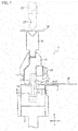
- a mold 1 for a press brake is used by being mounted on a lower table 3 in a press brake (the overall configuration thereof is not shown), and includes a mold base 5 mountable on the lower table 3.
- the mold base 5 is formed long in a horizontal direction (a direction vertical to the page surface in FIG. 1 and an X-axis direction).
- An upward protruding portion 7 long in the horizontal direction is provided at the central portion on an upper surface of the mold base 5 and in a front-back direction (a Y-axis direction).
- a die holder 11 as an ascending and descending member that can detach and replace a die 9 is vertically movably provided on the upward protruding portion 7. More specifically, the die holder (ascending and descending member) 11 is provided with a lower surface 13 that can abut on an upper surface of the upward protruding portion 7, and a suspending portion 15 that vertically movably comes in surface contact with a vertical rear surface 7A of the upward protruding portion 7 is integrally provided with the die holder 11.
- a workpiece pressing member 17 that vertically movably comes in surface contact with a vertical front surface 7B of the upward protruding portion 7 and is long in the horizontal direction is provided on the die holder 11 detachably and replaceably via an attachment tool 19 such as a screw.
- a workpiece supporting member 21 that vertically faces the workpiece pressing member 17 and is long in the horizontal direction is provided on the mold base 5 detachably and replaceably.
- an actuator 23 for vertical movement such as a fluid pressure cylinder is installed in the mold base 5.
- a biasing (an energizing) unit such as a coil spring is provided instead of the actuator 23 for vertical movement to press and bias (energize) the die holder 11 in an upward direction at all times.
- the die holder 11 is detachably and replaceably provided with the die 9 that works with a punch 27 detachably and replaceably provided on an upper table 25 in the press brake to perform bending of a plate-like workpiece W.
- the mold 1 has a function of pressurizing an end edge of the plate-like workpiece W to reduce residual stress at the end edge. More specifically, the configuration is such that the end edge of the workpiece W is pressurized between the lower surface of the workpiece pressing member 17 and the upper surface of the workpiece supporting member 21. That is, when the lower surface 13 of the die holder 11 abuts on the upper surface of the upward protruding portion 7 in the mold base 5, the lower surface of the workpiece pressing member 17 and the upper surface of the workpiece supporting member 21 come into contact with each other, or are slightly away from each other.
- An upper surface 21F of the workpiece supporting member 21 is formed as an inclined surface with the front side (the right side in FIG. 1 ) being low, and a lower surface 17F of the workpiece pressing member 17, which is a pressurizing surface, is formed as a level surface. That is, the upper surface 21F of the workpiece supporting member 21 is inclined so that the front side (the right side in FIG. 1 ) when guiding the workpiece W between the workpiece pressing member 17 and the workpiece supporting member 21 becomes lower. Accordingly, the workpiece W can be easily inserted between the workpiece pressing member 17 and the workpiece supporting member 21 from the front side.
- the end edge of the workpiece W abuts on the front surface 7B of the upward protruding portion 7 and is positioned. Accordingly, the front surface 7B of the upward protruding portion 7 constitutes a guide surface along which the workpiece pressing member 17 slides vertically, and constitutes a workpiece positioning surface with which the workpiece W is brought into contact to perform positioning.
- the end edge of the workpiece W corresponds to a topmost portion of the inclined upper surface 21F of the workpiece supporting member 21. Accordingly, when the upper table 25 in the press brake is relatively lowered to press the die 9, the workpiece pressing member 17 is lowered, and the lower surface 17F comes into contact with the workpiece W to press the workpiece W. In this stage, the contact between the end edge of the workpiece W and the upper surface 21F of the workpiece supporting member 21 becomes line contact.
- the contact between the end edge of the workpiece W and the inclined upper surface 21F of the workpiece supporting member 21 changes from the initial line contact to the surface contact by pressurization, the vicinity of the end edge of the workpiece W can be pressurized up to the upper yield point stress in the range where the surface contact is small, and the residual stress can be reduced. It is relative as to whether to form the upper surface 21F of the workpiece supporting member 21 as an inclined surface or to form the lower surface 17F of the workpiece pressing member 17 as an inclined surface. Therefore, it suffices to form at least one of the lower surface 17F of the workpiece pressing member 17 and the upper surface 21F of the workpiece supporting member 21 as an inclined surface.
- the lower surface 17F of the workpiece pressing member 17 can be formed as an inclined surface with the front side thereof becoming gradually higher, or as shown in FIG. 2(B) , the lower surface 17F can be formed as a curved surface with the front side thereof becoming gradually higher.
- a curved surface or an inclined surface can be formed at a rear-side part of the lower surface 17F of the workpiece pressing member 17, and a front-side part thereof can be a level surface. In the respective configurations, hemming can be performed between the lower surface 17F of the workpiece pressing member 17 and the upper surface 21F of the workpiece supporting member 21.
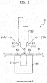
- FIG. 3 is an explanatory diagram of a mold according to a second embodiment.
- a mold 51 according to the second embodiment includes an upper mold (a punch) 53 mountable on an upper table (not shown) in a press brake, and a lower mold (a die) 55 mountable on a lower table (not shown).
- the lower mold 55 includes a bending groove 57 with which the upper mold 53 can be engaged at the time of bending a workpiece W in a V shape.
- An upper surface 59 of the lower mold 55 is formed as a level surface.
- the upper mold 53 includes a workpiece pressing portion 61 formed in a V shape at a lower part thereof to press the workpiece W into the bending groove 57.
- a pressurizing surface 63 that can pressurize the workpiece W by putting the workpiece W between the upper surface 59 of the lower mold 55 and the pressurizing surface 63 is provided at an upper position of the workpiece pressing portion 61.
- the pressurizing surface 63 is formed by forming a step portion on the both front and rear sides of a base end portion of the workpiece pressing portion 61 in the upper mold 53.
- the pressurizing surface 63 is formed at the step portion positioned inside of extending portions 61A on the V-shaped inclined surfaces of the workpiece pressing portion 61. Accordingly, when bending of the workpiece W in a V shape is performed by the workpiece pressing portion 61, the pressurizing surface 63 does not interfere with the workpiece W.
- the pressurizing surfaces 63 are slightly inclined so that the both front and rear sides become higher than a middle portion, respectively.
- the pressurizing surface 63 can be formed as a curved surface or the like as in the configuration of the lower surface 17F shown in FIGS. 2(B) and 2(C) .
- the workpiece pressing portion 61 of the upper mold 53 is engaged with the bending groove 57 in the lower mold 55 and is held in a state where the upper surface 59 of the lower mold 55 and the pressurizing surface 63 of the upper mold 53 are slightly away from each other.
- the end edge of the workpiece W is then inserted between the upper surface 59 and the pressurizing surface 63 and is brought into contact with a vertical front surface 61F or a vertical rear surface 61R in the workpiece pressing portion 61, to perform positioning of the end edge of the workpiece W.
- the front surface 61F and the rear surface 61R of the workpiece pressing portion 61 in the upper mold 53 constitute a workpiece positioning surface with which the end edge of the workpiece W is brought into contact to perform positioning.
- the workpiece W is placed and positioned on the upper surface 59 of the lower mold 55, and the workpiece W is pressed into the bending groove 57 in the lower mold 55 by the workpiece pressing portion 61 of the upper mold 53, thereby enabling to perform bending on the workpiece W in the V shape.
- the workpiece W bent in an acute angle beforehand is placed on the upper surface 21F of the workpiece supporting member 21, and a bent portion WB of the workpiece W is positioned so as to abut on the front surface 7B of the upward protruding portion 7.
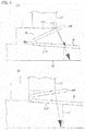
- a front end edge 17E of the lower surface 17F in the workpiece pressing member 17 presses the flange portion WF (see FIG. 4(A) ).
- a pressing direction of the workpiece pressing member 17 is a direction vertical to an inclined surface of the flange portion WF.
- the flange portion WF is further pressed and bent to gradually decrease a bending angle of the workpiece W, and the pressing direction with respect to the flange portion WF by the front end edge 17E of the workpiece pressing member 17 is gradually changed to the vertical direction (see FIG. 4(B) ).
- the lower surface 17F of the workpiece pressing member 17 gradually comes into surface contact with (against) the flange portion WF of the workpiece W, and the contact position gradually shifts in a direction toward the bent portion WB (see FIGS. 5(A) and 5(B) ).
- the pressing force of the workpiece pressing member 17 to press the flange portion WF increases more on the side of the bent portion WB than on the end side of the flange portion WF (see FIG. 5(B) ).
- the workpiece W strongly presses the upper surface 21F of the workpiece supporting member 21 corresponding to the position where the workpiece pressing member 17 presses the flange portion WF downward (see FIG. 5(B) ). That is, the vicinity of the position where the workpiece pressing member 17 presses the flange portion WF and the vicinity of the position where the workpiece W presses the upper surface 21F of the workpiece supporting member 21 face each other vertically.
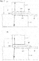
- the position where the workpiece pressing member 17 presses the flange portion WF is a position closer to the end side of the flange portion WF than a bending central position of the bent portion WB. Therefore, downward moment acts on the end side of the flange portion WF, and the end side of the flange portion WF becomes a detached and free state from the lower surface 17F of the workpiece pressing member 17 (see FIG. 7(A) ).
- the position where the workpiece W presses the upper surface 21F of the workpiece supporting member 21 is a position substantially vertically facing (corresponding) the position where the workpiece pressing member 17 presses the flange portion WF and is a position on the opposite side of the bent portion WB, with the bending central position of the bent portion WB therebetween.
- a reaction force when the workpiece W presses the upper surface 21F acts on the workpiece W.
- the workpiece W becomes the free state detached from the end edge of the upper surface 21F of the workpiece supporting member 21 due to the moment caused by the reaction force (see FIG. 7(A) ). That is, a free end side of the workpiece W (the right end side in FIGS. 7(A) and 7(B) ) is held in the state detached from the lower surface (the pressurizing surface) 17F of the workpiece pressing member 17 and the upper surface 21F of the workpiece supporting member 21.
- the end side of the flange portion WF abuts on the upper surface of the workpiece W (see FIG. 7(B) ).
- an area where the lower surface 17F of the workpiece pressing member 17 pressurizes the workpiece W and an area where the upper surface 21F of the workpiece supporting member 21 pressurizes the workpiece W are areas of pressing upper and lower curved surfaces in the bent portion WB of the workpiece W which are small. Accordingly, even if stress concentration occurs and a pressing force (a pressurizing force) of the workpiece pressing member 17 is relatively small, hemming can be performed.
- the bent portion WB of the workpiece W undergoes deformation in the left direction in FIGS. 8(A) and (8B ), and is strongly pressed to the front surface 7B of the upward protruding portion 7 (see FIG. 8(B) ). Accordingly, the curved surface of the bent portion WB undergoes deformation by being pressed to the front surface 7B. That is, a planar portion is formed by being pressed to the front surface 7B in a part of the smooth curved surface in the bent portion WB.
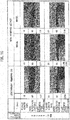
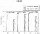
- two types of plate thickness after hemming written vertically indicate a thickness of the bent portion WB in the flange portion WF of the workpiece W and a thickness in a state where the end side of the flange portion WF is detached.
- the plate thickness can be made thinner by a mold in which the upper surface 21F of the workpiece supporting member 21 is formed low on the front side (the new hemming method).
- the plate thickness after hemming can be made thinner even if the pressurization load is small (for example, in the case of 40 tons and 42 tons) (see FIGS. 9 to 11 ).
- Hemming of workpieces made of various materials has been performed, with the inclination angle of the upper surface 21F being held constant. It is desired to use a detachable and replaceable workpiece supporting member 21 having different inclination angles of the upper surface 21F corresponding to the material and the plate thickness of a workpiece.
- molds 1A and 1B as shown in FIGS. 12(A) and 12(B) were prepared.
- the overall configuration of the molds 1A and 1B is substantially the same as the configuration of the mold 1 described above. Therefore, constituent elements having like functions are denoted by like reference characters, and redundant descriptions thereof will be omitted.
- the mold 1A shown in FIG. 12(A) has a configuration in which an elastic member 7C such as rubber that can abut on a workpiece W is provided in the front surface 7B of the upward protruding portion 7 so as to slightly protrude frontward (rightward in FIG. 12(A) ).
- the mold 1B shown in FIG. 12(B) has a configuration in which a striking member 7D is biased (energized) frontward by an elastic member 7S such as a coil spring installed in the upward protruding portion 7 so as to protrude slightly.
- the elastic member 7C and the striking member 7D are respectively provided in plural in the horizontal direction with an appropriate interval.
- an initial contact state between an end edge of the workpiece and the workpiece pressing member is line contact, because an upper surface of the workpiece supporting member is inclined relatively to a lower surface of the workpiece pressing member. Therefore, even if an initial pressurizing force is small, stress concentration occurs at the end edge of the workpiece, thereby enabling to reduce residual stress at the end edge of the workpiece.
Landscapes
- Engineering & Computer Science (AREA)
- Mechanical Engineering (AREA)
- Bending Of Plates, Rods, And Pipes (AREA)
- Straightening Metal Sheet-Like Bodies (AREA)
Applications Claiming Priority (4)
| Application Number | Priority Date | Filing Date | Title |
|---|---|---|---|
| JP2014075088 | 2014-04-01 | ||
| JP2014264686A JP2015199122A (ja) | 2014-04-01 | 2014-12-26 | プレスブレーキ用金型及びヘミング加工方法 |
| PCT/JP2015/059883 WO2015152142A1 (ja) | 2014-04-01 | 2015-03-30 | プレスブレーキ用金型及びヘミング加工方法 |
| EP15773240.5A EP3127627B1 (de) | 2014-04-01 | 2015-03-30 | Form für eine biegepresse und falzverfahren |
Related Parent Applications (2)
| Application Number | Title | Priority Date | Filing Date |
|---|---|---|---|
| EP15773240.5A Division EP3127627B1 (de) | 2014-04-01 | 2015-03-30 | Form für eine biegepresse und falzverfahren |
| EP15773240.5A Division-Into EP3127627B1 (de) | 2014-04-01 | 2015-03-30 | Form für eine biegepresse und falzverfahren |
Publications (2)
| Publication Number | Publication Date |
|---|---|
| EP3511087A1 true EP3511087A1 (de) | 2019-07-17 |
| EP3511087B1 EP3511087B1 (de) | 2024-05-29 |
Family
ID=54240465
Family Applications (2)
| Application Number | Title | Priority Date | Filing Date |
|---|---|---|---|
| EP15773240.5A Active EP3127627B1 (de) | 2014-04-01 | 2015-03-30 | Form für eine biegepresse und falzverfahren |
| EP19152487.5A Active EP3511087B1 (de) | 2014-04-01 | 2015-03-30 | Werkzeug für eine biegepresse |
Family Applications Before (1)
| Application Number | Title | Priority Date | Filing Date |
|---|---|---|---|
| EP15773240.5A Active EP3127627B1 (de) | 2014-04-01 | 2015-03-30 | Form für eine biegepresse und falzverfahren |
Country Status (4)
| Country | Link |
|---|---|
| US (2) | US10576522B2 (de) |
| EP (2) | EP3127627B1 (de) |
| JP (1) | JP2015199122A (de) |
| WO (1) | WO2015152142A1 (de) |
Families Citing this family (4)
| Publication number | Priority date | Publication date | Assignee | Title |
|---|---|---|---|---|
| JP2017159328A (ja) * | 2016-03-10 | 2017-09-14 | 株式会社アマダホールディングス | ヘミングダイシステム |
| CN111774460B (zh) * | 2020-06-29 | 2025-03-25 | 安徽擎天伟嘉装备制造有限公司 | 一种冷柜围板端部迷宫成型装置 |
| CN115193976B (zh) * | 2022-06-28 | 2025-09-23 | 天津金力研汽车工程技术有限公司 | 一种应用于包边模具中的浮动包边机构 |
| JP2025154082A (ja) * | 2024-03-29 | 2025-10-10 | 株式会社オートネットワーク技術研究所 | 金属部材および金属部材の製造方法 |
Citations (6)
| Publication number | Priority date | Publication date | Assignee | Title |
|---|---|---|---|---|
| JPH10137852A (ja) * | 1996-11-11 | 1998-05-26 | Murai Kogyo Kk | 折り曲げ、平押し金型 |
| JPH11197763A (ja) * | 1998-01-14 | 1999-07-27 | Honda Motor Co Ltd | ヘミング構造およびヘミング装置 |
| WO2010099559A1 (de) * | 2009-03-04 | 2010-09-10 | Trumpf Maschinen Austria Gmbh & Co. Kg. | Verfahren und werkzeug zum freibiegen mit einem einstellbaren gesenk |
| JP2012157902A (ja) | 2011-01-14 | 2012-08-23 | Amada Co Ltd | 板材の折曲げ加工方法及び残留応力増減装置 |
| JP2013116502A (ja) | 2011-11-04 | 2013-06-13 | Amada Co Ltd | 板材の加工装置、押圧金型および金型設置体 |
| JP2014075088A (ja) | 2012-10-05 | 2014-04-24 | Canon Inc | 画像形成装置、制御方法、およびそのプログラム。 |
Family Cites Families (20)
| Publication number | Priority date | Publication date | Assignee | Title |
|---|---|---|---|---|
| FR2276106A1 (fr) | 1974-06-26 | 1976-01-23 | Cegedur | Procede de vernissage des parois internes d'un tube d'aluminium de grande longueur |
| CH639412A5 (de) | 1978-02-18 | 1983-11-15 | Woodman Trevor P | Farbe zur spektral selektiven beschichtung von metalloberflaechen und verwendung der farbe. |
| JPS5680327A (en) | 1979-12-05 | 1981-07-01 | Yanagisawa Seisakusho:Kk | Composite bending apparatus |
| JPS6056123A (ja) | 1983-09-06 | 1985-04-01 | Honda Motor Co Ltd | V型エンジンを搭載した自動二輪車の吸気装置 |
| JPS6066622A (ja) | 1983-09-19 | 1985-04-16 | 三菱電機株式会社 | 過電流保護装置 |
| JPS6056123U (ja) * | 1983-09-24 | 1985-04-19 | 関東自動車工業株式会社 | プレスヘミング機 |
| JPS6066622U (ja) * | 1983-10-07 | 1985-05-11 | 北日本サツシ工業株式会社 | 鋼板折曲用型具 |
| JPH01271011A (ja) * | 1988-04-22 | 1989-10-30 | Osamu Makino | プレス曲げ加工用工具 |
| JP2569858B2 (ja) * | 1990-02-02 | 1997-01-08 | トヨタ自動車株式会社 | ヘミング用プレス型 |
| JP3043386B2 (ja) | 1990-09-25 | 2000-05-22 | 森 勝司 | ミシン用刺しゅう器 |
| JP3551260B2 (ja) * | 1992-06-26 | 2004-08-04 | 東栄工業株式会社 | 小型、軽量ヘミング金型 |
| JP3494671B2 (ja) * | 1993-02-19 | 2004-02-09 | 三洋機工株式会社 | ヘミング加工装置 |
| JP3043386U (ja) | 1997-05-13 | 1997-11-18 | 株式会社マツカワキカイ | 板体折曲機の下駒のベッド |
| US5966976A (en) * | 1997-11-19 | 1999-10-19 | Amada Metrecs Company, Limited | Compression working method and compression working apparatus |
| US6257043B1 (en) * | 1999-12-30 | 2001-07-10 | Unova Ip Corp. | Modified flat hem apparatus and method |
| JP4502304B2 (ja) * | 2001-12-17 | 2010-07-14 | 株式会社アマダ | ヘミングダイ |
| JP2004042061A (ja) * | 2002-07-09 | 2004-02-12 | Sumitomo Light Metal Ind Ltd | ヘム部を有するアルミニウム合金板部材 |
| JP4587713B2 (ja) * | 2004-06-14 | 2010-11-24 | 株式会社アマダ | ヘミングダイおよびヘミング金型装置 |
| US7975521B2 (en) * | 2009-04-14 | 2011-07-12 | Osamu Makino | Bending tool for a bending press |
| AT513741B1 (de) * | 2013-03-28 | 2014-07-15 | Trumpf Maschinen Austria Gmbh | Biegewerkzeuge zum Vorbiegen und Zudrücken |
-
2014
- 2014-12-26 JP JP2014264686A patent/JP2015199122A/ja active Pending
-
2015
- 2015-03-30 EP EP15773240.5A patent/EP3127627B1/de active Active
- 2015-03-30 US US15/124,918 patent/US10576522B2/en active Active
- 2015-03-30 EP EP19152487.5A patent/EP3511087B1/de active Active
- 2015-03-30 WO PCT/JP2015/059883 patent/WO2015152142A1/ja not_active Ceased
-
2020
- 2020-01-21 US US16/747,924 patent/US11638947B2/en active Active
Patent Citations (6)
| Publication number | Priority date | Publication date | Assignee | Title |
|---|---|---|---|---|
| JPH10137852A (ja) * | 1996-11-11 | 1998-05-26 | Murai Kogyo Kk | 折り曲げ、平押し金型 |
| JPH11197763A (ja) * | 1998-01-14 | 1999-07-27 | Honda Motor Co Ltd | ヘミング構造およびヘミング装置 |
| WO2010099559A1 (de) * | 2009-03-04 | 2010-09-10 | Trumpf Maschinen Austria Gmbh & Co. Kg. | Verfahren und werkzeug zum freibiegen mit einem einstellbaren gesenk |
| JP2012157902A (ja) | 2011-01-14 | 2012-08-23 | Amada Co Ltd | 板材の折曲げ加工方法及び残留応力増減装置 |
| JP2013116502A (ja) | 2011-11-04 | 2013-06-13 | Amada Co Ltd | 板材の加工装置、押圧金型および金型設置体 |
| JP2014075088A (ja) | 2012-10-05 | 2014-04-24 | Canon Inc | 画像形成装置、制御方法、およびそのプログラム。 |
Also Published As
| Publication number | Publication date |
|---|---|
| EP3511087B1 (de) | 2024-05-29 |
| EP3127627A4 (de) | 2018-01-10 |
| US20170021403A1 (en) | 2017-01-26 |
| EP3127627A1 (de) | 2017-02-08 |
| EP3127627B1 (de) | 2023-08-02 |
| US11638947B2 (en) | 2023-05-02 |
| JP2015199122A (ja) | 2015-11-12 |
| US10576522B2 (en) | 2020-03-03 |
| US20200156135A1 (en) | 2020-05-21 |
| WO2015152142A1 (ja) | 2015-10-08 |
Similar Documents
| Publication | Publication Date | Title |
|---|---|---|
| US11638947B2 (en) | Mold for press brake | |
| US20140283576A1 (en) | Sheet material processing apparatus, press die, and die setting body | |
| CN112496137A (zh) | 具有弯曲凸部的帽型截面部件的制造装置及制造方法 | |
| CN111819053A (zh) | 模切刀具和用于切割金属板的方法 | |
| JP7050984B2 (ja) | ワーク端縁の残留応力低減方法 | |
| CN104511522A (zh) | 锥面工件斜孔冲模 | |
| US12551939B2 (en) | Bending method | |
| JP2013128963A (ja) | プレス加工方法およびプレス加工装置 | |
| MX2021008959A (es) | Metodo de formacion por prensado y aparato de prensado. | |
| JP7042119B2 (ja) | プレス装置 | |
| JP2007075888A (ja) | プレス打ち抜き方法およびプレス打ち抜き型およびばね | |
| JP2013146750A (ja) | 板材折曲げ加工方法及び板材折曲げ加工機 | |
| JP7064729B1 (ja) | シート状ワークの打抜き刃 | |
| KR101384899B1 (ko) | 역방향 스크랩 취출용 펀칭프레스 | |
| CN102248063B (zh) | 一种冲孔模具的冲孔机构 | |
| JP2005342772A (ja) | プレス用打抜き金型装置及びこれを用いたプレス打抜き方法 | |
| JP6846267B2 (ja) | 下型装置及びワークの折曲げ加工方法 | |
| JP4149158B2 (ja) | 金型装置 | |
| JP2020049498A (ja) | ヘミング加工用パンチ金型及びヘミング加工用ダイ金型 | |
| JP2019166571A (ja) | せん断加工方法及びせん断加工装置 | |
| CN111215523A (zh) | 一种支架弯曲成型装置 | |
| JP2021074757A (ja) | 開先を有する部材の製造方法および開先加工装置 | |
| JP5183869B2 (ja) | 面取り加工方法に使用するパンチ金型並びに金型 | |
| JP2008213019A (ja) | 薄板打抜き加工方法及び打抜き加工装置 | |
| JP2007118045A (ja) | 薄板金属の絞り及び打ち抜きの同一工程加工方法及びその装置 |
Legal Events
| Date | Code | Title | Description |
|---|---|---|---|
| PUAI | Public reference made under article 153(3) epc to a published international application that has entered the european phase |
Free format text: ORIGINAL CODE: 0009012 |
|
| STAA | Information on the status of an ep patent application or granted ep patent |
Free format text: STATUS: REQUEST FOR EXAMINATION WAS MADE |
|
| 17P | Request for examination filed |
Effective date: 20190118 |
|
| AC | Divisional application: reference to earlier application |
Ref document number: 3127627 Country of ref document: EP Kind code of ref document: P |
|
| AK | Designated contracting states |
Kind code of ref document: A1 Designated state(s): AL AT BE BG CH CY CZ DE DK EE ES FI FR GB GR HR HU IE IS IT LI LT LU LV MC MK MT NL NO PL PT RO RS SE SI SK SM TR |
|
| STAA | Information on the status of an ep patent application or granted ep patent |
Free format text: STATUS: EXAMINATION IS IN PROGRESS |
|
| 17Q | First examination report despatched |
Effective date: 20220803 |
|
| P01 | Opt-out of the competence of the unified patent court (upc) registered |
Effective date: 20230527 |
|
| GRAP | Despatch of communication of intention to grant a patent |
Free format text: ORIGINAL CODE: EPIDOSNIGR1 |
|
| STAA | Information on the status of an ep patent application or granted ep patent |
Free format text: STATUS: GRANT OF PATENT IS INTENDED |
|
| INTG | Intention to grant announced |
Effective date: 20240205 |
|
| RIN1 | Information on inventor provided before grant (corrected) |
Inventor name: KOBAYASHI, SHIN Inventor name: HAYASHI, SHIRO Inventor name: SHIBATA, TAKAHIRO Inventor name: YIN, YINGJUN |
|
| GRAS | Grant fee paid |
Free format text: ORIGINAL CODE: EPIDOSNIGR3 |
|
| GRAA | (expected) grant |
Free format text: ORIGINAL CODE: 0009210 |
|
| STAA | Information on the status of an ep patent application or granted ep patent |
Free format text: STATUS: THE PATENT HAS BEEN GRANTED |
|
| AC | Divisional application: reference to earlier application |
Ref document number: 3127627 Country of ref document: EP Kind code of ref document: P |
|
| AK | Designated contracting states |
Kind code of ref document: B1 Designated state(s): AL AT BE BG CH CY CZ DE DK EE ES FI FR GB GR HR HU IE IS IT LI LT LU LV MC MK MT NL NO PL PT RO RS SE SI SK SM TR |
|
| REG | Reference to a national code |
Ref country code: CH Ref legal event code: EP |
|
| REG | Reference to a national code |
Ref country code: IE Ref legal event code: FG4D |
|
| REG | Reference to a national code |
Ref country code: DE Ref legal event code: R096 Ref document number: 602015088873 Country of ref document: DE |
|
| REG | Reference to a national code |
Ref country code: LT Ref legal event code: MG9D |
|
| REG | Reference to a national code |
Ref country code: NL Ref legal event code: MP Effective date: 20240529 |
|
| PG25 | Lapsed in a contracting state [announced via postgrant information from national office to epo] |
Ref country code: IS Free format text: LAPSE BECAUSE OF FAILURE TO SUBMIT A TRANSLATION OF THE DESCRIPTION OR TO PAY THE FEE WITHIN THE PRESCRIBED TIME-LIMIT Effective date: 20240929 |
|
| PG25 | Lapsed in a contracting state [announced via postgrant information from national office to epo] |
Ref country code: BG Free format text: LAPSE BECAUSE OF FAILURE TO SUBMIT A TRANSLATION OF THE DESCRIPTION OR TO PAY THE FEE WITHIN THE PRESCRIBED TIME-LIMIT Effective date: 20240529 |
|
| PG25 | Lapsed in a contracting state [announced via postgrant information from national office to epo] |
Ref country code: HR Free format text: LAPSE BECAUSE OF FAILURE TO SUBMIT A TRANSLATION OF THE DESCRIPTION OR TO PAY THE FEE WITHIN THE PRESCRIBED TIME-LIMIT Effective date: 20240529 Ref country code: FI Free format text: LAPSE BECAUSE OF FAILURE TO SUBMIT A TRANSLATION OF THE DESCRIPTION OR TO PAY THE FEE WITHIN THE PRESCRIBED TIME-LIMIT Effective date: 20240529 |
|
| PG25 | Lapsed in a contracting state [announced via postgrant information from national office to epo] |
Ref country code: GR Free format text: LAPSE BECAUSE OF FAILURE TO SUBMIT A TRANSLATION OF THE DESCRIPTION OR TO PAY THE FEE WITHIN THE PRESCRIBED TIME-LIMIT Effective date: 20240830 |
|
| REG | Reference to a national code |
Ref country code: AT Ref legal event code: MK05 Ref document number: 1690209 Country of ref document: AT Kind code of ref document: T Effective date: 20240529 |
|
| PG25 | Lapsed in a contracting state [announced via postgrant information from national office to epo] |
Ref country code: ES Free format text: LAPSE BECAUSE OF FAILURE TO SUBMIT A TRANSLATION OF THE DESCRIPTION OR TO PAY THE FEE WITHIN THE PRESCRIBED TIME-LIMIT Effective date: 20240529 |
|
| PG25 | Lapsed in a contracting state [announced via postgrant information from national office to epo] |
Ref country code: AT Free format text: LAPSE BECAUSE OF FAILURE TO SUBMIT A TRANSLATION OF THE DESCRIPTION OR TO PAY THE FEE WITHIN THE PRESCRIBED TIME-LIMIT Effective date: 20240529 |
|
| PG25 | Lapsed in a contracting state [announced via postgrant information from national office to epo] |
Ref country code: PL Free format text: LAPSE BECAUSE OF FAILURE TO SUBMIT A TRANSLATION OF THE DESCRIPTION OR TO PAY THE FEE WITHIN THE PRESCRIBED TIME-LIMIT Effective date: 20240529 |
|
| PG25 | Lapsed in a contracting state [announced via postgrant information from national office to epo] |
Ref country code: LV Free format text: LAPSE BECAUSE OF FAILURE TO SUBMIT A TRANSLATION OF THE DESCRIPTION OR TO PAY THE FEE WITHIN THE PRESCRIBED TIME-LIMIT Effective date: 20240529 |
|
| PG25 | Lapsed in a contracting state [announced via postgrant information from national office to epo] |
Ref country code: PL Free format text: LAPSE BECAUSE OF FAILURE TO SUBMIT A TRANSLATION OF THE DESCRIPTION OR TO PAY THE FEE WITHIN THE PRESCRIBED TIME-LIMIT Effective date: 20240529 Ref country code: NO Free format text: LAPSE BECAUSE OF FAILURE TO SUBMIT A TRANSLATION OF THE DESCRIPTION OR TO PAY THE FEE WITHIN THE PRESCRIBED TIME-LIMIT Effective date: 20240829 Ref country code: LV Free format text: LAPSE BECAUSE OF FAILURE TO SUBMIT A TRANSLATION OF THE DESCRIPTION OR TO PAY THE FEE WITHIN THE PRESCRIBED TIME-LIMIT Effective date: 20240529 Ref country code: IS Free format text: LAPSE BECAUSE OF FAILURE TO SUBMIT A TRANSLATION OF THE DESCRIPTION OR TO PAY THE FEE WITHIN THE PRESCRIBED TIME-LIMIT Effective date: 20240929 Ref country code: HR Free format text: LAPSE BECAUSE OF FAILURE TO SUBMIT A TRANSLATION OF THE DESCRIPTION OR TO PAY THE FEE WITHIN THE PRESCRIBED TIME-LIMIT Effective date: 20240529 Ref country code: GR Free format text: LAPSE BECAUSE OF FAILURE TO SUBMIT A TRANSLATION OF THE DESCRIPTION OR TO PAY THE FEE WITHIN THE PRESCRIBED TIME-LIMIT Effective date: 20240830 Ref country code: FI Free format text: LAPSE BECAUSE OF FAILURE TO SUBMIT A TRANSLATION OF THE DESCRIPTION OR TO PAY THE FEE WITHIN THE PRESCRIBED TIME-LIMIT Effective date: 20240529 Ref country code: ES Free format text: LAPSE BECAUSE OF FAILURE TO SUBMIT A TRANSLATION OF THE DESCRIPTION OR TO PAY THE FEE WITHIN THE PRESCRIBED TIME-LIMIT Effective date: 20240529 Ref country code: BG Free format text: LAPSE BECAUSE OF FAILURE TO SUBMIT A TRANSLATION OF THE DESCRIPTION OR TO PAY THE FEE WITHIN THE PRESCRIBED TIME-LIMIT Effective date: 20240529 Ref country code: AT Free format text: LAPSE BECAUSE OF FAILURE TO SUBMIT A TRANSLATION OF THE DESCRIPTION OR TO PAY THE FEE WITHIN THE PRESCRIBED TIME-LIMIT Effective date: 20240529 Ref country code: RS Free format text: LAPSE BECAUSE OF FAILURE TO SUBMIT A TRANSLATION OF THE DESCRIPTION OR TO PAY THE FEE WITHIN THE PRESCRIBED TIME-LIMIT Effective date: 20240829 |
|
| PG25 | Lapsed in a contracting state [announced via postgrant information from national office to epo] |
Ref country code: NL Free format text: LAPSE BECAUSE OF FAILURE TO SUBMIT A TRANSLATION OF THE DESCRIPTION OR TO PAY THE FEE WITHIN THE PRESCRIBED TIME-LIMIT Effective date: 20240529 |
|
| PG25 | Lapsed in a contracting state [announced via postgrant information from national office to epo] |
Ref country code: NL Free format text: LAPSE BECAUSE OF FAILURE TO SUBMIT A TRANSLATION OF THE DESCRIPTION OR TO PAY THE FEE WITHIN THE PRESCRIBED TIME-LIMIT Effective date: 20240529 |
|
| PG25 | Lapsed in a contracting state [announced via postgrant information from national office to epo] |
Ref country code: DK Free format text: LAPSE BECAUSE OF FAILURE TO SUBMIT A TRANSLATION OF THE DESCRIPTION OR TO PAY THE FEE WITHIN THE PRESCRIBED TIME-LIMIT Effective date: 20240529 |
|
| PG25 | Lapsed in a contracting state [announced via postgrant information from national office to epo] |
Ref country code: EE Free format text: LAPSE BECAUSE OF FAILURE TO SUBMIT A TRANSLATION OF THE DESCRIPTION OR TO PAY THE FEE WITHIN THE PRESCRIBED TIME-LIMIT Effective date: 20240529 |
|
| PG25 | Lapsed in a contracting state [announced via postgrant information from national office to epo] |
Ref country code: CZ Free format text: LAPSE BECAUSE OF FAILURE TO SUBMIT A TRANSLATION OF THE DESCRIPTION OR TO PAY THE FEE WITHIN THE PRESCRIBED TIME-LIMIT Effective date: 20240529 |
|
| PG25 | Lapsed in a contracting state [announced via postgrant information from national office to epo] |
Ref country code: RO Free format text: LAPSE BECAUSE OF FAILURE TO SUBMIT A TRANSLATION OF THE DESCRIPTION OR TO PAY THE FEE WITHIN THE PRESCRIBED TIME-LIMIT Effective date: 20240529 Ref country code: SK Free format text: LAPSE BECAUSE OF FAILURE TO SUBMIT A TRANSLATION OF THE DESCRIPTION OR TO PAY THE FEE WITHIN THE PRESCRIBED TIME-LIMIT Effective date: 20240529 |
|
| PG25 | Lapsed in a contracting state [announced via postgrant information from national office to epo] |
Ref country code: SM Free format text: LAPSE BECAUSE OF FAILURE TO SUBMIT A TRANSLATION OF THE DESCRIPTION OR TO PAY THE FEE WITHIN THE PRESCRIBED TIME-LIMIT Effective date: 20240529 |
|
| PG25 | Lapsed in a contracting state [announced via postgrant information from national office to epo] |
Ref country code: SM Free format text: LAPSE BECAUSE OF FAILURE TO SUBMIT A TRANSLATION OF THE DESCRIPTION OR TO PAY THE FEE WITHIN THE PRESCRIBED TIME-LIMIT Effective date: 20240529 Ref country code: SK Free format text: LAPSE BECAUSE OF FAILURE TO SUBMIT A TRANSLATION OF THE DESCRIPTION OR TO PAY THE FEE WITHIN THE PRESCRIBED TIME-LIMIT Effective date: 20240529 Ref country code: RO Free format text: LAPSE BECAUSE OF FAILURE TO SUBMIT A TRANSLATION OF THE DESCRIPTION OR TO PAY THE FEE WITHIN THE PRESCRIBED TIME-LIMIT Effective date: 20240529 Ref country code: EE Free format text: LAPSE BECAUSE OF FAILURE TO SUBMIT A TRANSLATION OF THE DESCRIPTION OR TO PAY THE FEE WITHIN THE PRESCRIBED TIME-LIMIT Effective date: 20240529 Ref country code: DK Free format text: LAPSE BECAUSE OF FAILURE TO SUBMIT A TRANSLATION OF THE DESCRIPTION OR TO PAY THE FEE WITHIN THE PRESCRIBED TIME-LIMIT Effective date: 20240529 Ref country code: CZ Free format text: LAPSE BECAUSE OF FAILURE TO SUBMIT A TRANSLATION OF THE DESCRIPTION OR TO PAY THE FEE WITHIN THE PRESCRIBED TIME-LIMIT Effective date: 20240529 |
|
| PG25 | Lapsed in a contracting state [announced via postgrant information from national office to epo] |
Ref country code: IT Free format text: LAPSE BECAUSE OF FAILURE TO SUBMIT A TRANSLATION OF THE DESCRIPTION OR TO PAY THE FEE WITHIN THE PRESCRIBED TIME-LIMIT Effective date: 20240529 |
|
| REG | Reference to a national code |
Ref country code: DE Ref legal event code: R097 Ref document number: 602015088873 Country of ref document: DE |
|
| PLBE | No opposition filed within time limit |
Free format text: ORIGINAL CODE: 0009261 |
|
| STAA | Information on the status of an ep patent application or granted ep patent |
Free format text: STATUS: NO OPPOSITION FILED WITHIN TIME LIMIT |
|
| PG25 | Lapsed in a contracting state [announced via postgrant information from national office to epo] |
Ref country code: SI Free format text: LAPSE BECAUSE OF FAILURE TO SUBMIT A TRANSLATION OF THE DESCRIPTION OR TO PAY THE FEE WITHIN THE PRESCRIBED TIME-LIMIT Effective date: 20240529 |
|
| 26N | No opposition filed |
Effective date: 20250303 |
|
| PG25 | Lapsed in a contracting state [announced via postgrant information from national office to epo] |
Ref country code: SE Free format text: LAPSE BECAUSE OF FAILURE TO SUBMIT A TRANSLATION OF THE DESCRIPTION OR TO PAY THE FEE WITHIN THE PRESCRIBED TIME-LIMIT Effective date: 20240529 |
|
| PG25 | Lapsed in a contracting state [announced via postgrant information from national office to epo] |
Ref country code: MC Free format text: LAPSE BECAUSE OF FAILURE TO SUBMIT A TRANSLATION OF THE DESCRIPTION OR TO PAY THE FEE WITHIN THE PRESCRIBED TIME-LIMIT Effective date: 20240529 |
|
| REG | Reference to a national code |
Ref country code: CH Ref legal event code: H13 Free format text: ST27 STATUS EVENT CODE: U-0-0-H10-H13 (AS PROVIDED BY THE NATIONAL OFFICE) Effective date: 20251024 |
|
| PG25 | Lapsed in a contracting state [announced via postgrant information from national office to epo] |
Ref country code: LU Free format text: LAPSE BECAUSE OF NON-PAYMENT OF DUE FEES Effective date: 20250330 |
|
| GBPC | Gb: european patent ceased through non-payment of renewal fee |
Effective date: 20250330 |
|
| REG | Reference to a national code |
Ref country code: BE Ref legal event code: MM Effective date: 20250331 |
|
| PG25 | Lapsed in a contracting state [announced via postgrant information from national office to epo] |
Ref country code: GB Free format text: LAPSE BECAUSE OF NON-PAYMENT OF DUE FEES Effective date: 20250330 |
|
| PG25 | Lapsed in a contracting state [announced via postgrant information from national office to epo] |
Ref country code: FR Free format text: LAPSE BECAUSE OF NON-PAYMENT OF DUE FEES Effective date: 20250331 |
|
| PG25 | Lapsed in a contracting state [announced via postgrant information from national office to epo] |
Ref country code: BE Free format text: LAPSE BECAUSE OF NON-PAYMENT OF DUE FEES Effective date: 20250331 |
|
| PG25 | Lapsed in a contracting state [announced via postgrant information from national office to epo] |
Ref country code: CH Free format text: LAPSE BECAUSE OF NON-PAYMENT OF DUE FEES Effective date: 20250331 |
|
| PG25 | Lapsed in a contracting state [announced via postgrant information from national office to epo] |
Ref country code: IE Free format text: LAPSE BECAUSE OF NON-PAYMENT OF DUE FEES Effective date: 20250330 |
|
| PGFP | Annual fee paid to national office [announced via postgrant information from national office to epo] |
Ref country code: DE Payment date: 20260319 Year of fee payment: 12 |
|
| PG25 | Lapsed in a contracting state [announced via postgrant information from national office to epo] |
Ref country code: CY Free format text: LAPSE BECAUSE OF FAILURE TO SUBMIT A TRANSLATION OF THE DESCRIPTION OR TO PAY THE FEE WITHIN THE PRESCRIBED TIME-LIMIT Effective date: 20240529 |
|
| PG25 | Lapsed in a contracting state [announced via postgrant information from national office to epo] |
Ref country code: LT Free format text: LAPSE BECAUSE OF FAILURE TO SUBMIT A TRANSLATION OF THE DESCRIPTION OR TO PAY THE FEE WITHIN THE PRESCRIBED TIME-LIMIT Effective date: 20240529 |
|
| PG25 | Lapsed in a contracting state [announced via postgrant information from national office to epo] |
Ref country code: TR Free format text: LAPSE BECAUSE OF FAILURE TO SUBMIT A TRANSLATION OF THE DESCRIPTION OR TO PAY THE FEE WITHIN THE PRESCRIBED TIME-LIMIT Effective date: 20240529 |
|
| PG25 | Lapsed in a contracting state [announced via postgrant information from national office to epo] |
Ref country code: PT Free format text: LAPSE BECAUSE OF NON-PAYMENT OF DUE FEES Effective date: 20240529 |