EP3511164A1 - Structure de support pour impression tridimensionnelle - Google Patents
Structure de support pour impression tridimensionnelle Download PDFInfo
- Publication number
- EP3511164A1 EP3511164A1 EP18151831.7A EP18151831A EP3511164A1 EP 3511164 A1 EP3511164 A1 EP 3511164A1 EP 18151831 A EP18151831 A EP 18151831A EP 3511164 A1 EP3511164 A1 EP 3511164A1
- Authority
- EP
- European Patent Office
- Prior art keywords
- support structure
- bellows
- printed
- building plate
- dimensional printing
- Prior art date
- Legal status (The legal status is an assumption and is not a legal conclusion. Google has not performed a legal analysis and makes no representation as to the accuracy of the status listed.)
- Withdrawn
Links
Images


Classifications
-
- B—PERFORMING OPERATIONS; TRANSPORTING
- B29—WORKING OF PLASTICS; WORKING OF SUBSTANCES IN A PLASTIC STATE IN GENERAL
- B29C—SHAPING OR JOINING OF PLASTICS; SHAPING OF MATERIAL IN A PLASTIC STATE, NOT OTHERWISE PROVIDED FOR; AFTER-TREATMENT OF THE SHAPED PRODUCTS, e.g. REPAIRING
- B29C64/00—Additive manufacturing, i.e. manufacturing of three-dimensional [3D] objects by additive deposition, additive agglomeration or additive layering, e.g. by 3D printing, stereolithography or selective laser sintering
- B29C64/30—Auxiliary operations or equipment
- B29C64/379—Handling of additively manufactured objects, e.g. using robots
-
- B—PERFORMING OPERATIONS; TRANSPORTING
- B22—CASTING; POWDER METALLURGY
- B22F—WORKING METALLIC POWDER; MANUFACTURE OF ARTICLES FROM METALLIC POWDER; MAKING METALLIC POWDER; APPARATUS OR DEVICES SPECIALLY ADAPTED FOR METALLIC POWDER
- B22F10/00—Additive manufacturing of workpieces or articles from metallic powder
- B22F10/20—Direct sintering or melting
-
- B—PERFORMING OPERATIONS; TRANSPORTING
- B22—CASTING; POWDER METALLURGY
- B22F—WORKING METALLIC POWDER; MANUFACTURE OF ARTICLES FROM METALLIC POWDER; MAKING METALLIC POWDER; APPARATUS OR DEVICES SPECIALLY ADAPTED FOR METALLIC POWDER
- B22F10/00—Additive manufacturing of workpieces or articles from metallic powder
- B22F10/40—Structures for supporting workpieces or articles during manufacture and removed afterwards
- B22F10/47—Structures for supporting workpieces or articles during manufacture and removed afterwards characterised by structural features
-
- B—PERFORMING OPERATIONS; TRANSPORTING
- B22—CASTING; POWDER METALLURGY
- B22F—WORKING METALLIC POWDER; MANUFACTURE OF ARTICLES FROM METALLIC POWDER; MAKING METALLIC POWDER; APPARATUS OR DEVICES SPECIALLY ADAPTED FOR METALLIC POWDER
- B22F10/00—Additive manufacturing of workpieces or articles from metallic powder
- B22F10/60—Treatment of workpieces or articles after build-up
- B22F10/66—Treatment of workpieces or articles after build-up by mechanical means
-
- B—PERFORMING OPERATIONS; TRANSPORTING
- B29—WORKING OF PLASTICS; WORKING OF SUBSTANCES IN A PLASTIC STATE IN GENERAL
- B29C—SHAPING OR JOINING OF PLASTICS; SHAPING OF MATERIAL IN A PLASTIC STATE, NOT OTHERWISE PROVIDED FOR; AFTER-TREATMENT OF THE SHAPED PRODUCTS, e.g. REPAIRING
- B29C64/00—Additive manufacturing, i.e. manufacturing of three-dimensional [3D] objects by additive deposition, additive agglomeration or additive layering, e.g. by 3D printing, stereolithography or selective laser sintering
- B29C64/10—Processes of additive manufacturing
- B29C64/141—Processes of additive manufacturing using only solid materials
- B29C64/153—Processes of additive manufacturing using only solid materials using layers of powder being selectively joined, e.g. by selective laser sintering or melting
-
- B—PERFORMING OPERATIONS; TRANSPORTING
- B29—WORKING OF PLASTICS; WORKING OF SUBSTANCES IN A PLASTIC STATE IN GENERAL
- B29C—SHAPING OR JOINING OF PLASTICS; SHAPING OF MATERIAL IN A PLASTIC STATE, NOT OTHERWISE PROVIDED FOR; AFTER-TREATMENT OF THE SHAPED PRODUCTS, e.g. REPAIRING
- B29C64/00—Additive manufacturing, i.e. manufacturing of three-dimensional [3D] objects by additive deposition, additive agglomeration or additive layering, e.g. by 3D printing, stereolithography or selective laser sintering
- B29C64/20—Apparatus for additive manufacturing; Details thereof or accessories therefor
- B29C64/245—Platforms or substrates
-
- B—PERFORMING OPERATIONS; TRANSPORTING
- B29—WORKING OF PLASTICS; WORKING OF SUBSTANCES IN A PLASTIC STATE IN GENERAL
- B29C—SHAPING OR JOINING OF PLASTICS; SHAPING OF MATERIAL IN A PLASTIC STATE, NOT OTHERWISE PROVIDED FOR; AFTER-TREATMENT OF THE SHAPED PRODUCTS, e.g. REPAIRING
- B29C64/00—Additive manufacturing, i.e. manufacturing of three-dimensional [3D] objects by additive deposition, additive agglomeration or additive layering, e.g. by 3D printing, stereolithography or selective laser sintering
- B29C64/40—Structures for supporting 3D objects during manufacture and intended to be sacrificed after completion thereof
-
- B—PERFORMING OPERATIONS; TRANSPORTING
- B33—ADDITIVE MANUFACTURING TECHNOLOGY
- B33Y—ADDITIVE MANUFACTURING, i.e. MANUFACTURING OF THREE-DIMENSIONAL [3D] OBJECTS BY ADDITIVE DEPOSITION, ADDITIVE AGGLOMERATION OR ADDITIVE LAYERING, e.g. BY 3D PRINTING, STEREOLITHOGRAPHY OR SELECTIVE LASER SINTERING
- B33Y10/00—Processes of additive manufacturing
-
- B—PERFORMING OPERATIONS; TRANSPORTING
- B33—ADDITIVE MANUFACTURING TECHNOLOGY
- B33Y—ADDITIVE MANUFACTURING, i.e. MANUFACTURING OF THREE-DIMENSIONAL [3D] OBJECTS BY ADDITIVE DEPOSITION, ADDITIVE AGGLOMERATION OR ADDITIVE LAYERING, e.g. BY 3D PRINTING, STEREOLITHOGRAPHY OR SELECTIVE LASER SINTERING
- B33Y30/00—Apparatus for additive manufacturing; Details thereof or accessories therefor
-
- B—PERFORMING OPERATIONS; TRANSPORTING
- B33—ADDITIVE MANUFACTURING TECHNOLOGY
- B33Y—ADDITIVE MANUFACTURING, i.e. MANUFACTURING OF THREE-DIMENSIONAL [3D] OBJECTS BY ADDITIVE DEPOSITION, ADDITIVE AGGLOMERATION OR ADDITIVE LAYERING, e.g. BY 3D PRINTING, STEREOLITHOGRAPHY OR SELECTIVE LASER SINTERING
- B33Y40/00—Auxiliary operations or equipment, e.g. for material handling
- B33Y40/20—Post-treatment, e.g. curing, coating or polishing
Definitions
- the present disclosure is directed to a support structure for supporting a part, which is printed by means of a three-dimensional printing system, according to claim 1. Furthermore, the present disclosure is directed to a use of a support structure for supporting a printed part according to claim 8, a method of printing a part three-dimensionally by means of a three-dimensional printing system according to claim 9 and a method of breaking a connection between a building plate and a printed part according to claim 11.
- the building plate comprises a metal plate on top of which melted material is deposited layer by layer until the complete part is obtained.
- support structures connect the printed part with the building plate. These support structures are geometries which allow a deposition of overhanging material during a printing process.
- the support structures In order to free the printed part from the building plate, the support structures have to be cut or removed. In case of metal parts this is usually done using machine tools like band/wire saws or electrical discharge machines. As an alternative, the cutting/removing can be done manually, using hand tools like pliers, chisels or hammers.
- EP 3 067 332 A1 discloses a method for manufacturing a three-dimensional structure, including forming a glass pattern on a base member and then separating the glass pattern from the base member. For the purpose of separating base member and printed structure an additional separation aid layer is produced by applying non-sinterable paste on the surface of the base member.
- An objective of the present invention is to facilitate a breaking of the connection between a part printed by means of a three-dimensional printing system and a building plate, the printed part is attached to.
- a support structure for supporting a printed part and establishing a connection of a building plate to the printed part, which part is printed by means of a three-dimensional printing system, the support structure being arrangeable on the building plate of the three-dimensional printing system, according to claim 1.
- the problem is also solved by a method of breaking a connection between a building plate and a printed part according to claim 11.
- At least one part of the support structure is designed to change its outer shape when there is an external force on the support structure. Due to the changeability of the support structure the connection of the building plate to the printed part is breakable by means of an external force. Thereby, the supported printed part can be detached.
- the printed part can be freed from the building plate without any cutting or breaking devices/tools. There is no need of performing machining operations. Thus, the time needed for the removal of the printed part from the building plate can be reduced significantly. More than this, manual supports removal operations performed with hand tools, which can generate health and safety risks and constitute a source of variability in a quality of the printed part, are avoided.
- the at least one part of the support structure being designed to change its outer dimensions when there is an external force on the support structure, is designed as a bellows.
- the geometry of a bellows makes it flexible and gives it the capability of elongating when an external force, e.g. a pressure of a fluid, is applied on its internal surface.
- Bellows are usually used in applications where a flexible joint is needed to accommodate displacements of adjacent parts or when parts have to deform under pressure, e.g. in joints for pressurized pipes.
- Their basic shape is cylindrical, but in the course of the invention every possible shape can be used.
- the bellows is arranged at a center portion of the support structure to divide the support structure into three parts: one first part below the bellows, one second part above the bellows and the bellows as one third part.
- the bellows is interposed in the support structure so as to divide the structure into three parts.
- the first part (below the bellows) is adjacent to the building plate, while the second part is adjacent to the printed part.
- the bellows comprises one open end portion and one closed end portion, wherein the open end portion preferably comprises a pipe connector.
- the open end can be used to deform the bellows and break the support structure, e.g. by filling in a fluid into an inner part of the bellows.
- the filling can be advantageously facilitated using a pipe connector which is arranged on the open end portion of the bellows.
- the at least one part of the support structure is lattice-shaped, wherein the lattice-shaped part is connected to the bellows by means of geometries which break in case the bellows elongates when an external force is applied on the bellows.
- Such geometries usually have a sharp section reduction that generates a stress concentration in the point of minimum section. This shape allows a predictable breaking of the supports when the bellows is deformed by means of an external force.
- the at least one part of the support structure is shaped according to a projected area of the printed part with respect to the building plate.
- the at least one part of the support structure respectively the bellows is shaped according to a footprint of the printed part on the building plate.
- the footprint can be rectangular or circular.
- the support structure is printed by the three-dimensional printing system.
- the support structure especially comprising the bellows, is printable together with the part by means of the three-dimensional printing system.
- the part can be directly printed on top of the support structure, forming a single material block.
- the problem is also solved by using a support structure according to the invention for supporting a printed part and establishing a connection of a building plate to the printed part, which part is printed by means of a three-dimensional printing system.
- the problem is further solved by a method of printing a part three-dimensionally by means of a three-dimensional printing system, wherein the method comprises the following steps:
- the support structure is preferably printed by means of a three-dimensional printing system and is arranged on the building plate and connected to the building plate. Most preferably, the support structure is printed by means of the same three-dimensional printing system as the (actual) printed part.
- a support structure that is not printed, especially not printed by the same three-dimensional printing system. But it is essential that the support structure is designed to change its outer shape when there is an external force on the support structure. It is also possible to use a support structure which is partly printed, especially by the same three-dimensional printing system as the printed part, and partly not printed. For example, an (external) not printed bellows can be used as one part of the support structure while the other parts of the support structure above and below the bellows are printed, especially by the same three-dimensional printing system as the printed part.
- the problem is also solved by a method of breaking a connection between a building plate and a printed part, the connection being established by means of a support structure according to the invention, and the part having been printed on the support structure by means of a three-dimensional printing system.
- the method comprises the following steps:
- the elongation of the bellows causes a break of the connection between the bellows and the first and second part of the support structure, being arranged above and below the bellows.
- the printed part can be detached from the building part easily, without machine or manual tools or the like.
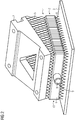
- Figure 1 there is depicted a support structure 1 for supporting a part 2 and connecting the part 2 to a building plate 3.
- the part 2 has been printed by a three-dimensional printing system (not shown) and has been deposited on the support structure 1 in order to allow a deposition of overhanging material during the printing process.
- the support structure 1 In order to free the printed part 2 from the building plate 3, the support structure 1 has to be cut or removed. In case of metal parts this is usually done using machine tools like band/wire saws or electrical discharge machines. As an alternative, the cutting/removing can be done manually, using hand tools like pliers, chisels or hammers.
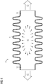
- Figure 2 shows a support structure 1 according to the invention.
- the support structure 1 connects the printed part 2 to the building plate 3. It comprises a first part 6, being arranged on the building plate 3, and a second part 5, being arranged below the printed part 2. Additionally, the support structure 1 comprises a third part 4 which is arranged at a center portion 10 of the support structure 1, above the first part 6 and below the second part 5.
- the third part 4 is designed as a bellows 4.
- the bellows 4 is rectangular-shaped according to a projected area or footprint of the printed part 2.
- the bellows 4 is arranged parallel to the building plate 3, which is not mandatory. In contrast, any useful orientation of the bellows 4 in relation to the building plate 3 is possible.
- the bellows 4 comprises a pipe connector 8, forming one open end portion 9.
- Other types of connectors as the one shown in Figure 2 are also possible, e.g. threaded connectors.
- the end portion 7 arranged oppositely from the open end portion is closed (not visible in Fig. 2 ).
- the bellows 4 is printed by the same three-dimensional printing system as the (actual) printed part 2.
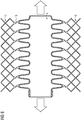
- Figures 3 and 4 illustrate a general functional principle of a cylindrical bellows 4.
- the bellows 4 comprises a corrugated portion 11 and two smooth end portions 12, 13.
- the geometry of the bellows 4 makes it flexible and gives it the capability of elongating when a pressure 14 is applied on its internal surface.
- Figure 4 illustrates the longitudinal elongation 15 of the bellows 4 in case of an application of an internal pressure 14.
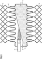
- the first part 6 and the second part 5 of the support structure 1 are lattice-shaped and connect the bellows 4 with the building plate 3 respectively the printed part 2. Connection is made by means of geometries 16 that are breakable if the bellows 4 expands/elongates.
- Figure 5 illustrates the lattice-shaped first part 6 and second part 5 as well as the connecting geometries 16.
- Figure 6 illustrates a breaking of the geometries 16 when the bellows 4 is elongating due to an internal application of pressure 14.
- the support structure 1 according to the invention allows a predictable breaking of connection between the printed part 2 and the building plate 3 when the bellows 4 is deformed.
- a support structure 1 according to the invention is arranged on a building plate 3 by means of the three-dimensional printing system. Thereby, the support structure 1 is connected to the building plate 3 by chemical and/or physical adhesion.
- the part 2 is printed on the support structure 1, strictly speaking on the second part 5 of the support structure 1, by means of a three-dimensional printing system, wherein the support structure 1 connects the building plate 3 to the printed part 2.
- FIG. 7 shows the bellows 4 filled completely with the powder.
- Figure 8 illustrates a removal of the powder 17 by means of the pipe connector 8, using e.g. pressurized air or a vacuum cleaner.
- a conduit 18 conveying a pressurized fluid is connected to the pipe connector 8 of the bellows 4. Pressure is applied to the fluid which fills an interior of the bellows 4. The bellows 4 elongates due to the applied pressure 14. Thereby, the connections 16 are broken and the printed part 2 is freed from the building plate 3.
- the printed part 2 can be detached from the building plate 3.
Landscapes
- Engineering & Computer Science (AREA)
- Chemical & Material Sciences (AREA)
- Materials Engineering (AREA)
- Manufacturing & Machinery (AREA)
- Physics & Mathematics (AREA)
- Optics & Photonics (AREA)
- Mechanical Engineering (AREA)
- Robotics (AREA)
- Printing Methods (AREA)
Priority Applications (5)
| Application Number | Priority Date | Filing Date | Title |
|---|---|---|---|
| EP18151831.7A EP3511164A1 (fr) | 2018-01-16 | 2018-01-16 | Structure de support pour impression tridimensionnelle |
| US16/767,335 US20200384694A1 (en) | 2018-01-16 | 2019-01-09 | Support structure for three-dimensional printing |
| PCT/EP2019/050398 WO2019141556A1 (fr) | 2018-01-16 | 2019-01-09 | Structure porteuse destinée à une impression en trois dimensions |
| CN201980008658.8A CN111836720B (zh) | 2018-01-16 | 2019-01-09 | 用于三维打印的支撑结构 |
| EP19701984.7A EP3703949B1 (fr) | 2018-01-16 | 2019-01-09 | Structure de support pour impression tridimensionnelle |
Applications Claiming Priority (1)
| Application Number | Priority Date | Filing Date | Title |
|---|---|---|---|
| EP18151831.7A EP3511164A1 (fr) | 2018-01-16 | 2018-01-16 | Structure de support pour impression tridimensionnelle |
Publications (1)
| Publication Number | Publication Date |
|---|---|
| EP3511164A1 true EP3511164A1 (fr) | 2019-07-17 |
Family
ID=61131916
Family Applications (2)
| Application Number | Title | Priority Date | Filing Date |
|---|---|---|---|
| EP18151831.7A Withdrawn EP3511164A1 (fr) | 2018-01-16 | 2018-01-16 | Structure de support pour impression tridimensionnelle |
| EP19701984.7A Active EP3703949B1 (fr) | 2018-01-16 | 2019-01-09 | Structure de support pour impression tridimensionnelle |
Family Applications After (1)
| Application Number | Title | Priority Date | Filing Date |
|---|---|---|---|
| EP19701984.7A Active EP3703949B1 (fr) | 2018-01-16 | 2019-01-09 | Structure de support pour impression tridimensionnelle |
Country Status (4)
| Country | Link |
|---|---|
| US (1) | US20200384694A1 (fr) |
| EP (2) | EP3511164A1 (fr) |
| CN (1) | CN111836720B (fr) |
| WO (1) | WO2019141556A1 (fr) |
Cited By (2)
| Publication number | Priority date | Publication date | Assignee | Title |
|---|---|---|---|---|
| CN110465660A (zh) * | 2019-07-29 | 2019-11-19 | 浙江大学 | 一种悬垂圆截面流道的轻量化主动支撑结构 |
| EP3797973A1 (fr) * | 2019-09-30 | 2021-03-31 | Siemens Energy Global GmbH & Co. KG | Structure de support améliorée |
Families Citing this family (10)
| Publication number | Priority date | Publication date | Assignee | Title |
|---|---|---|---|---|
| WO2019209310A1 (fr) * | 2018-04-27 | 2019-10-31 | Hewlett-Packard Development Company, L.P. | Retrait de matériau de construction |
| CN112743101B (zh) * | 2020-12-29 | 2023-01-24 | 南京晨光集团有限责任公司 | 一种用于条状或片状结构件slm成形的开裂控制方法 |
| EP4023365A1 (fr) * | 2021-01-05 | 2022-07-06 | Siemens Energy Global GmbH & Co. KG | Stratégie de soutien pour structure additive à paroi mince |
| WO2022187720A1 (fr) | 2021-03-05 | 2022-09-09 | Saint-Gobain Abrasives, Inc. | Articles abrasifs et leurs procédés de formation |
| JP2024509813A (ja) | 2021-03-05 | 2024-03-05 | サンーゴバン アブレイシブズ,インコーポレイティド | 研磨物品及びそれを形成するための方法 |
| CN115194179B (zh) * | 2021-04-12 | 2024-07-05 | 中国航发商用航空发动机有限责任公司 | 支撑结构件及螺旋管路的制造方法 |
| EP4457058A4 (fr) | 2021-12-30 | 2026-01-07 | Saint Gobain Abrasives Inc | Articles abrasifs et leurs procédés de formation |
| CN118591435A (zh) | 2021-12-30 | 2024-09-03 | 圣戈班磨料磨具有限公司 | 磨料制品及其形成方法 |
| US20240068604A1 (en) * | 2022-08-30 | 2024-02-29 | Relativity Space, Inc. | Additively manufactured bellows |
| US20250326036A1 (en) * | 2023-04-24 | 2025-10-23 | Howmedica Osteonics Corp. | Breakaway Covers for Use in Processing Build Structures With Porous Regions |
Citations (4)
| Publication number | Priority date | Publication date | Assignee | Title |
|---|---|---|---|---|
| US20120308805A1 (en) * | 2011-05-31 | 2012-12-06 | Sella Nadav | Solid freeform fabrication of easily removeable support constructions |
| DE102014004870A1 (de) * | 2014-04-04 | 2015-10-08 | Airbus Defence and Space GmbH | Abstützvorrichtung und Fertigungsvorrichtung für ein generatives Fertigungsverfahren, sowie damit durchführbares generatives Fertigungsverfahren |
| EP3067332A1 (fr) | 2013-11-06 | 2016-09-14 | Toray Industries, Inc. | Procédé de fabrication d'une structure tridimensionnelle, procédé de fabrication d'un panneau scintillateur, structure tridimensionnelle et panneau scintillateur |
| WO2016161276A1 (fr) * | 2015-04-03 | 2016-10-06 | Materialise N.V. | Structures de support dans une impression 3d |
Family Cites Families (11)
| Publication number | Priority date | Publication date | Assignee | Title |
|---|---|---|---|---|
| JP3809078B2 (ja) * | 2001-04-10 | 2006-08-16 | 賢三 松尾 | 建物設計支援システム |
| US20150192919A1 (en) * | 2015-03-24 | 2015-07-09 | Caterpillar Inc. | Support members for three dimensional object printing |
| GB201505217D0 (en) | 2015-03-26 | 2015-05-13 | Gripple Ltd | Gripping arrangement |
| KR101644017B1 (ko) * | 2015-04-10 | 2016-07-29 | 제주대학교 산학협력단 | 3차원 프린팅 구조물의 지지 구조 적층 시스템 및 이를 이용한 3차원 프린팅 방법 |
| DK3118394T3 (da) * | 2015-07-13 | 2022-06-20 | Siemens Gamesa Renewable Energy As | Fremgangsmåde til konstruktion af et tårn og en 3D-tårnprintindretning |
| DE102015119746A1 (de) * | 2015-11-16 | 2017-05-18 | Cl Schutzrechtsverwaltungs Gmbh | Verfahren zur Herstellung einer Stützstruktur zur Stützung eines generativ auszubildenden dreidimensionalen Objekts |
| US20170173891A1 (en) * | 2015-12-21 | 2017-06-22 | Stratasys, Inc. | Gravitational supports in additive manufacturing system |
| CA3040921C (fr) * | 2016-12-06 | 2024-02-20 | Markforged, Inc. | Fabrication additive avec alimentation en materiau assoupli a la chaleur |
| CN106853686B (zh) * | 2017-02-24 | 2019-06-28 | 浙江工贸职业技术学院 | 可调远近程传输方式的3d打印机的送丝加热装置 |
| CN206733613U (zh) * | 2017-05-18 | 2017-12-12 | 重庆长教科技有限公司 | 一种新型光固化3d打印机自动加料装置 |
| CN107214962A (zh) * | 2017-06-28 | 2017-09-29 | 宁夏共享模具有限公司 | 一种阵列式3d打印头 |
-
2018
- 2018-01-16 EP EP18151831.7A patent/EP3511164A1/fr not_active Withdrawn
-
2019
- 2019-01-09 EP EP19701984.7A patent/EP3703949B1/fr active Active
- 2019-01-09 WO PCT/EP2019/050398 patent/WO2019141556A1/fr not_active Ceased
- 2019-01-09 CN CN201980008658.8A patent/CN111836720B/zh not_active Expired - Fee Related
- 2019-01-09 US US16/767,335 patent/US20200384694A1/en not_active Abandoned
Patent Citations (4)
| Publication number | Priority date | Publication date | Assignee | Title |
|---|---|---|---|---|
| US20120308805A1 (en) * | 2011-05-31 | 2012-12-06 | Sella Nadav | Solid freeform fabrication of easily removeable support constructions |
| EP3067332A1 (fr) | 2013-11-06 | 2016-09-14 | Toray Industries, Inc. | Procédé de fabrication d'une structure tridimensionnelle, procédé de fabrication d'un panneau scintillateur, structure tridimensionnelle et panneau scintillateur |
| DE102014004870A1 (de) * | 2014-04-04 | 2015-10-08 | Airbus Defence and Space GmbH | Abstützvorrichtung und Fertigungsvorrichtung für ein generatives Fertigungsverfahren, sowie damit durchführbares generatives Fertigungsverfahren |
| WO2016161276A1 (fr) * | 2015-04-03 | 2016-10-06 | Materialise N.V. | Structures de support dans une impression 3d |
Cited By (5)
| Publication number | Priority date | Publication date | Assignee | Title |
|---|---|---|---|---|
| CN110465660A (zh) * | 2019-07-29 | 2019-11-19 | 浙江大学 | 一种悬垂圆截面流道的轻量化主动支撑结构 |
| EP3797973A1 (fr) * | 2019-09-30 | 2021-03-31 | Siemens Energy Global GmbH & Co. KG | Structure de support améliorée |
| WO2021063632A1 (fr) * | 2019-09-30 | 2021-04-08 | Siemens Energy Global GmbH & Co. KG | Structure de support perfectionnée |
| CN114450113A (zh) * | 2019-09-30 | 2022-05-06 | 西门子能源环球有限责任两合公司 | 改进的支撑结构 |
| US12472558B2 (en) | 2019-09-30 | 2025-11-18 | Siemens Energy Global GmbH & Co. KG | Support structure |
Also Published As
| Publication number | Publication date |
|---|---|
| EP3703949B1 (fr) | 2021-08-11 |
| CN111836720A (zh) | 2020-10-27 |
| US20200384694A1 (en) | 2020-12-10 |
| CN111836720B (zh) | 2022-06-21 |
| WO2019141556A1 (fr) | 2019-07-25 |
| EP3703949A1 (fr) | 2020-09-09 |
Similar Documents
| Publication | Publication Date | Title |
|---|---|---|
| EP3703949B1 (fr) | Structure de support pour impression tridimensionnelle | |
| US12146600B2 (en) | Pipe splitting apparatus with replaceable blade | |
| US6671955B2 (en) | Method for treating bodies after separation by breaking | |
| CN103447401A (zh) | 板状部件连结体,板状部件连结方法,及图像形成装置 | |
| WO2015113591A1 (fr) | Dispositif et procédé de détachement d'un premier substrat | |
| US8745833B2 (en) | Method of partially replacing shell plate of tower or vessel | |
| CN100515637C (zh) | 用来制造剖分型轴承结构的方法及加工装置 | |
| EP1112799A3 (fr) | Procédé et appareil pour insérer une électrode dans une machine d'usinage par électroérosion | |
| KR20190091398A (ko) | 관체형 제품 프레스 연속자동화 금형시스템 | |
| SE0950046A1 (sv) | Sammanhängande moduler för rör- eller kabelgenomföringar | |
| JP6635303B2 (ja) | チェーンのピン脱着装置 | |
| US20180318902A1 (en) | Method and device for manufacturing vehicle arm component | |
| JP6917834B2 (ja) | 樹脂管の施工方法、接続治具およびサドル固定治具 | |
| US3559632A (en) | Process and device for cleaving laminated materials | |
| US9327305B2 (en) | Cartridge block for multilayer ceramic screening | |
| WO2018087661A1 (fr) | Joint d'étanchéité auto-adhésif et son procédé de fabrication | |
| JP4485700B2 (ja) | 分割フランジ付き伸縮管継手 | |
| CN103894763A (zh) | 导线的送线焊接装置及方法 | |
| KR20170021195A (ko) | 취성 재료 기판에 있어서의 수직 크랙의 형성 방법 및 취성 재료 기판의 분단 방법 | |
| KR101564588B1 (ko) | 웨이퍼 브레이킹 보조장치 | |
| JPH11245122A (ja) | コンロッドのクラッキング方法およびクラッキング装置 | |
| CN119778358A (zh) | 一种静电吸盘的侧面填胶装置及方法 | |
| CN121156304A (zh) | 一种增材制造内流道支撑结构、增材制造方法及工件 | |
| KR20250170444A (ko) | 배관 절단 장치 | |
| JP2012239935A (ja) | 粘性材塗布装置 |
Legal Events
| Date | Code | Title | Description |
|---|---|---|---|
| PUAI | Public reference made under article 153(3) epc to a published international application that has entered the european phase |
Free format text: ORIGINAL CODE: 0009012 |
|
| AK | Designated contracting states |
Kind code of ref document: A1 Designated state(s): AL AT BE BG CH CY CZ DE DK EE ES FI FR GB GR HR HU IE IS IT LI LT LU LV MC MK MT NL NO PL PT RO RS SE SI SK SM TR |
|
| AX | Request for extension of the european patent |
Extension state: BA ME |
|
| STAA | Information on the status of an ep patent application or granted ep patent |
Free format text: STATUS: THE APPLICATION IS DEEMED TO BE WITHDRAWN |
|
| 18D | Application deemed to be withdrawn |
Effective date: 20200118 |