EP3511238A1 - Système flottant de plate-forme de génération d'énergie marine - Google Patents
Système flottant de plate-forme de génération d'énergie marine Download PDFInfo
- Publication number
- EP3511238A1 EP3511238A1 EP18799657.4A EP18799657A EP3511238A1 EP 3511238 A1 EP3511238 A1 EP 3511238A1 EP 18799657 A EP18799657 A EP 18799657A EP 3511238 A1 EP3511238 A1 EP 3511238A1
- Authority
- EP
- European Patent Office
- Prior art keywords
- pressure
- air
- buoyant bodies
- bellows
- ballast water
- Prior art date
- Legal status (The legal status is an assumption and is not a legal conclusion. Google has not performed a legal analysis and makes no representation as to the accuracy of the status listed.)
- Granted
Links
Images


Classifications
-
- B—PERFORMING OPERATIONS; TRANSPORTING
- B63—SHIPS OR OTHER WATERBORNE VESSELS; RELATED EQUIPMENT
- B63B—SHIPS OR OTHER WATERBORNE VESSELS; EQUIPMENT FOR SHIPPING
- B63B35/00—Vessels or similar floating structures specially adapted for specific purposes and not otherwise provided for
- B63B35/44—Floating buildings, stores, drilling platforms, or workshops, e.g. carrying water-oil separating devices
-
- B—PERFORMING OPERATIONS; TRANSPORTING
- B63—SHIPS OR OTHER WATERBORNE VESSELS; RELATED EQUIPMENT
- B63B—SHIPS OR OTHER WATERBORNE VESSELS; EQUIPMENT FOR SHIPPING
- B63B1/00—Hydrodynamic or hydrostatic features of hulls or of hydrofoils
- B63B1/02—Hydrodynamic or hydrostatic features of hulls or of hydrofoils deriving lift mainly from water displacement
- B63B1/10—Hydrodynamic or hydrostatic features of hulls or of hydrofoils deriving lift mainly from water displacement with multiple hulls
- B63B1/107—Semi-submersibles; Small waterline area multiple hull vessels and the like, e.g. SWATH
-
- B—PERFORMING OPERATIONS; TRANSPORTING
- B63—SHIPS OR OTHER WATERBORNE VESSELS; RELATED EQUIPMENT
- B63B—SHIPS OR OTHER WATERBORNE VESSELS; EQUIPMENT FOR SHIPPING
- B63B13/00—Conduits for emptying or ballasting; Self-bailing equipment; Scuppers
-
- B—PERFORMING OPERATIONS; TRANSPORTING
- B63—SHIPS OR OTHER WATERBORNE VESSELS; RELATED EQUIPMENT
- B63B—SHIPS OR OTHER WATERBORNE VESSELS; EQUIPMENT FOR SHIPPING
- B63B3/00—Hulls characterised by their structure or component parts
- B63B3/02—Hulls assembled from prefabricated sub-units
- B63B3/04—Hulls assembled from prefabricated sub-units with permanently-connected sub-units
- B63B3/06—Hulls assembled from prefabricated sub-units with permanently-connected sub-units the sub-units being substantially identical
-
- B—PERFORMING OPERATIONS; TRANSPORTING
- B63—SHIPS OR OTHER WATERBORNE VESSELS; RELATED EQUIPMENT
- B63B—SHIPS OR OTHER WATERBORNE VESSELS; EQUIPMENT FOR SHIPPING
- B63B43/00—Improving safety of vessels, e.g. damage control, not otherwise provided for
- B63B43/02—Improving safety of vessels, e.g. damage control, not otherwise provided for reducing risk of capsizing or sinking
- B63B43/04—Improving safety of vessels, e.g. damage control, not otherwise provided for reducing risk of capsizing or sinking by improving stability
- B63B43/06—Improving safety of vessels, e.g. damage control, not otherwise provided for reducing risk of capsizing or sinking by improving stability using ballast tanks
-
- B—PERFORMING OPERATIONS; TRANSPORTING
- B63—SHIPS OR OTHER WATERBORNE VESSELS; RELATED EQUIPMENT
- B63B—SHIPS OR OTHER WATERBORNE VESSELS; EQUIPMENT FOR SHIPPING
- B63B5/00—Hulls characterised by their construction of non-metallic material
- B63B5/14—Hulls characterised by their construction of non-metallic material made predominantly of concrete, e.g. reinforced
- B63B5/18—Hulls characterised by their construction of non-metallic material made predominantly of concrete, e.g. reinforced built-up from elements
- B63B5/20—Hulls characterised by their construction of non-metallic material made predominantly of concrete, e.g. reinforced built-up from elements in combination with elements of other materials
-
- B—PERFORMING OPERATIONS; TRANSPORTING
- B63—SHIPS OR OTHER WATERBORNE VESSELS; RELATED EQUIPMENT
- B63B—SHIPS OR OTHER WATERBORNE VESSELS; EQUIPMENT FOR SHIPPING
- B63B5/00—Hulls characterised by their construction of non-metallic material
- B63B5/14—Hulls characterised by their construction of non-metallic material made predominantly of concrete, e.g. reinforced
- B63B5/22—Hulls characterised by their construction of non-metallic material made predominantly of concrete, e.g. reinforced with reinforcing members external to shell
-
- F—MECHANICAL ENGINEERING; LIGHTING; HEATING; WEAPONS; BLASTING
- F03—MACHINES OR ENGINES FOR LIQUIDS; WIND, SPRING, OR WEIGHT MOTORS; PRODUCING MECHANICAL POWER OR A REACTIVE PROPULSIVE THRUST, NOT OTHERWISE PROVIDED FOR
- F03D—WIND MOTORS
- F03D13/00—Assembly, mounting or commissioning of wind motors; Arrangements specially adapted for transporting wind motor components
- F03D13/20—Arrangements for mounting or supporting wind motors; Masts or towers for wind motors
- F03D13/25—Arrangements for mounting or supporting wind motors; Masts or towers for wind motors specially adapted for offshore installation
-
- B—PERFORMING OPERATIONS; TRANSPORTING
- B63—SHIPS OR OTHER WATERBORNE VESSELS; RELATED EQUIPMENT
- B63B—SHIPS OR OTHER WATERBORNE VESSELS; EQUIPMENT FOR SHIPPING
- B63B1/00—Hydrodynamic or hydrostatic features of hulls or of hydrofoils
- B63B1/02—Hydrodynamic or hydrostatic features of hulls or of hydrofoils deriving lift mainly from water displacement
- B63B1/10—Hydrodynamic or hydrostatic features of hulls or of hydrofoils deriving lift mainly from water displacement with multiple hulls
- B63B1/12—Hydrodynamic or hydrostatic features of hulls or of hydrofoils deriving lift mainly from water displacement with multiple hulls the hulls being interconnected rigidly
- B63B2001/128—Hydrodynamic or hydrostatic features of hulls or of hydrofoils deriving lift mainly from water displacement with multiple hulls the hulls being interconnected rigidly comprising underwater connectors between the hulls
-
- B—PERFORMING OPERATIONS; TRANSPORTING
- B63—SHIPS OR OTHER WATERBORNE VESSELS; RELATED EQUIPMENT
- B63B—SHIPS OR OTHER WATERBORNE VESSELS; EQUIPMENT FOR SHIPPING
- B63B35/00—Vessels or similar floating structures specially adapted for specific purposes and not otherwise provided for
- B63B35/44—Floating buildings, stores, drilling platforms, or workshops, e.g. carrying water-oil separating devices
- B63B2035/4433—Floating structures carrying electric power plants
- B63B2035/446—Floating structures carrying electric power plants for converting wind energy into electric energy
-
- B—PERFORMING OPERATIONS; TRANSPORTING
- B63—SHIPS OR OTHER WATERBORNE VESSELS; RELATED EQUIPMENT
- B63B—SHIPS OR OTHER WATERBORNE VESSELS; EQUIPMENT FOR SHIPPING
- B63B2207/00—Buoyancy or ballast means
- B63B2207/02—Variable ballast or buoyancy
-
- B—PERFORMING OPERATIONS; TRANSPORTING
- B63—SHIPS OR OTHER WATERBORNE VESSELS; RELATED EQUIPMENT
- B63B—SHIPS OR OTHER WATERBORNE VESSELS; EQUIPMENT FOR SHIPPING
- B63B2207/00—Buoyancy or ballast means
- B63B2207/04—Pressure equalising or adjusting
-
- B—PERFORMING OPERATIONS; TRANSPORTING
- B63—SHIPS OR OTHER WATERBORNE VESSELS; RELATED EQUIPMENT
- B63B—SHIPS OR OTHER WATERBORNE VESSELS; EQUIPMENT FOR SHIPPING
- B63B2209/00—Energy supply or activating means
- B63B2209/20—Energy supply or activating means wind energy
-
- B—PERFORMING OPERATIONS; TRANSPORTING
- B63—SHIPS OR OTHER WATERBORNE VESSELS; RELATED EQUIPMENT
- B63B—SHIPS OR OTHER WATERBORNE VESSELS; EQUIPMENT FOR SHIPPING
- B63B2221/00—Methods and means for joining members or elements
- B63B2221/02—Methods and means for joining members or elements by welding
-
- F—MECHANICAL ENGINEERING; LIGHTING; HEATING; WEAPONS; BLASTING
- F05—INDEXING SCHEMES RELATING TO ENGINES OR PUMPS IN VARIOUS SUBCLASSES OF CLASSES F01-F04
- F05B—INDEXING SCHEME RELATING TO WIND, SPRING, WEIGHT, INERTIA OR LIKE MOTORS, TO MACHINES OR ENGINES FOR LIQUIDS COVERED BY SUBCLASSES F03B, F03D AND F03G
- F05B2240/00—Components
- F05B2240/90—Mounting on supporting structures or systems
- F05B2240/93—Mounting on supporting structures or systems on a structure floating on a liquid surface
- F05B2240/932—Mounting on supporting structures or systems on a structure floating on a liquid surface which is a catamaran-like structure
-
- F—MECHANICAL ENGINEERING; LIGHTING; HEATING; WEAPONS; BLASTING
- F05—INDEXING SCHEMES RELATING TO ENGINES OR PUMPS IN VARIOUS SUBCLASSES OF CLASSES F01-F04
- F05B—INDEXING SCHEME RELATING TO WIND, SPRING, WEIGHT, INERTIA OR LIKE MOTORS, TO MACHINES OR ENGINES FOR LIQUIDS COVERED BY SUBCLASSES F03B, F03D AND F03G
- F05B2240/00—Components
- F05B2240/90—Mounting on supporting structures or systems
- F05B2240/95—Mounting on supporting structures or systems offshore
-
- Y—GENERAL TAGGING OF NEW TECHNOLOGICAL DEVELOPMENTS; GENERAL TAGGING OF CROSS-SECTIONAL TECHNOLOGIES SPANNING OVER SEVERAL SECTIONS OF THE IPC; TECHNICAL SUBJECTS COVERED BY FORMER USPC CROSS-REFERENCE ART COLLECTIONS [XRACs] AND DIGESTS
- Y02—TECHNOLOGIES OR APPLICATIONS FOR MITIGATION OR ADAPTATION AGAINST CLIMATE CHANGE
- Y02E—REDUCTION OF GREENHOUSE GAS [GHG] EMISSIONS, RELATED TO ENERGY GENERATION, TRANSMISSION OR DISTRIBUTION
- Y02E10/00—Energy generation through renewable energy sources
- Y02E10/70—Wind energy
- Y02E10/72—Wind turbines with rotation axis in wind direction
-
- Y—GENERAL TAGGING OF NEW TECHNOLOGICAL DEVELOPMENTS; GENERAL TAGGING OF CROSS-SECTIONAL TECHNOLOGIES SPANNING OVER SEVERAL SECTIONS OF THE IPC; TECHNICAL SUBJECTS COVERED BY FORMER USPC CROSS-REFERENCE ART COLLECTIONS [XRACs] AND DIGESTS
- Y02—TECHNOLOGIES OR APPLICATIONS FOR MITIGATION OR ADAPTATION AGAINST CLIMATE CHANGE
- Y02E—REDUCTION OF GREENHOUSE GAS [GHG] EMISSIONS, RELATED TO ENERGY GENERATION, TRANSMISSION OR DISTRIBUTION
- Y02E10/00—Energy generation through renewable energy sources
- Y02E10/70—Wind energy
- Y02E10/727—Offshore wind turbines
-
- Y—GENERAL TAGGING OF NEW TECHNOLOGICAL DEVELOPMENTS; GENERAL TAGGING OF CROSS-SECTIONAL TECHNOLOGIES SPANNING OVER SEVERAL SECTIONS OF THE IPC; TECHNICAL SUBJECTS COVERED BY FORMER USPC CROSS-REFERENCE ART COLLECTIONS [XRACs] AND DIGESTS
- Y02—TECHNOLOGIES OR APPLICATIONS FOR MITIGATION OR ADAPTATION AGAINST CLIMATE CHANGE
- Y02P—CLIMATE CHANGE MITIGATION TECHNOLOGIES IN THE PRODUCTION OR PROCESSING OF GOODS
- Y02P70/00—Climate change mitigation technologies in the production process for final industrial or consumer products
- Y02P70/50—Manufacturing or production processes characterised by the final manufactured product
Definitions
- the present invention relates to a flotation system for an offshore power generation platform. More particularly, the present invention relates to a system of maintaining the structure and buoyancy of a buoyant body used in an offshore power generation platform upon wind power or solar power generation at an offshore location at sea.
- Such floating structures are used in offshore plants, container terminals, petroleum stockpiling facilities, offshore parks, or the like, and the scale thereof is also increasing.
- a floating structure is generally made of concrete and is a hollow rectangular parallelepiped-shaped structure.
- partition walls are generally mounted at regular intervals in an inner space thereof to define multiple hollow portions, and these hollow portions serve to create buoyancy of a buoyant body.
- buoyant body In the case of a typical concrete buoyant body, when cracks occur, seawater penetrates into the buoyant body due to water pressure, leading to a reduction in buoyancy. This can lead to a problem that the buoyant body may fail to serve as a stable buoyant body.
- a buoyancy maintaining method of floating a concrete structure as disclosed in Patent Document 1 includes an air bag mounted with a bag portion provided inside a hollow portion of the floating concrete structure and with an air inlet tube extending from the bag portion outwardly of the hollow portion for injecting air into the bag portion, wherein the air is injected into the air bag such that air pressure greater than at least draft pressure is introduced into the bag portion, and the bag portion is made larger in size than at least the hollow portion made in a standard size whereby the bag portion is brought into close contact with the inner surface of the hollow portion due to the air pressure introduced into the bag portion.
- a floating wind turbine platform as disclosed in Patent Document 2 regarding as a system for a floating offshore wind power generation includes: a) at least three stabilizing columns, each column having an upper and a lower end, and an internal volume for containing a ballast fluid; b) a tower having an upper end and a lower end that is coupled to the floating wind turbine platform; c) a turbine rotor coupled to an electrical generator, the turbine rotor and the electrical generator are mounted proximate to the upper end of the tower; d) main beams interconnected to the at least three stabilizing columns; e) water-entrapment plates, each of the plates attached to the lower end of one of the stabilizing columns; and f) a ballast control system for moving the ballast fluid between the internal volumes of the at least three stabilizing columns to adjust a vertical alignment of the tower.
- Patent Document 1 an outer wall of a buoyant body of Patent Document 1 is composed of a considerably thick concrete wall and thus is difficult to be transported to an offshore location. Furthermore, when cracks occur in the concrete wall, compressed air is supplemented into the air bag to prevent seawater from penetrating into the buoyant body. However, this may not effectively cope with a situation where the equilibrium between multiple buoyant bodies floating on the sea surface is upset due to continuous wind or storms. Additionally, Patent Document 1 has a structure in which air pressure corresponding to the draft pressure is injected, leading to a problem that the buoyant body is required to be extremely large in scale to stably float a large and heavy structure.
- Patent Document 2 as a method for maintaining equilibrium between multiple buoyant bodies (columns) when the equilibrium therebetween is upset due to continuous wind, the ballast fluid is used to flow between each of the stabilizing columns, thus maintaining the equilibrium between the buoyant bodies.
- an objective of the present invention is to provide a flotation system for an offshore power generation platform, the system being capable of reducing an overall weight of a buoyant body while maintaining strength thereof against water pressure, thus facilitating transportation to an offshore location at sea.
- Another objective of the present invention is to provide a flotation system for an offshore power generation platform, the system being relatively simple in structure and thus being capable of maintaining equilibrium between buoyant bodies even when the equilibrium is upset due to sea breeze or wind wave.
- Yet another objective of the present invention is to provide a flotation system for an offshore power generation platform, the system enabling easy manufacturing, mass manufacturing, and easy replacement and repair of parts.
- a flotation system for an offshore power generation platform comprising: multiple buoyant bodies each containing a high-pressure air and ballast water therein to create buoyancy; connecting members connecting the multiple buoyant bodies and a platform to each other, the platform on which a power generation facility is provided; ballast water flowing tubes through which the ballast water contained in the multiple buoyant bodies flows with respect to each other; a high-pressure tank supplying the high-pressure air into the multiple buoyant bodies; a compressor replenishing air pressure present in the high-pressure tank; an equilibrium sensor sensing an equilibrium state of each of the multiple buoyant bodies and transmitting a signal; a pressure sensor sensing pressure present in each of the multiple buoyant bodies and transmitting a signal; and a controller 800 controlling, in response to the signals from the equilibrium sensor and the pressure sensor, an amount of air supplied from the high-pressure tank 400 to the buoyant body where the buoyancy is required to increase and an amount of air discharged from the buoyant body where the
- the buoyant body may include: a bellows drum having a space defined therein, the space in which the high-pressure air and the ballast water are contained together; a ballast water inlet/outlet to which each of the ballast water flowing tubes through which the ballast water flows is connected; a high-pressure air inlet having an air inlet valve mounted thereat through which the high-pressure air is introduced from the high-pressure tank; an air outlet having an air outlet valve mounted thereat through which the air contained in the buoyant body is discharged; a sealing plate covering and sealing each upper and lower surface of the bellows drum; and a cover plate covering the sealing plate and to which each of the connecting members is secured.
- the power generation facility may be provided at a center of gravity of a geometrical figure defined by lines virtually connecting central portions of the multiple buoyant bodies to each other.
- the geometrical figure defined by the lines virtually connecting the central portions of the multiple buoyant bodies may be an equilateral triangle, and a wind power tower may be erected vertically at an outer center of the equilateral triangle.
- the bellows drum may be configured such that a bellows thereof is vertical bellows having a multi-layer structure in which ridges and troughs are vertically formed and multiple reinforcement rings are provided at regular intervals in a height direction, the reinforcement rings and the bellows being welded together.
- the bellows drum may be configured such that a bellows thereof is a horizontal bellows having a circumferentially divided structure in which ridges and troughs are horizontally formed, and multiple reinforcement plates are circumferentially provided at regular intervals, the reinforcement plates and the bellows being welded together.
- the bellows drum may be configured such that concrete or a foaming agent is applied on an outer surface thereof to provide surface protection and prevent surface corrosion.
- the flotation system for the offshore power generation platform having the above configuration, it is possible to achieve a weight reduction of the entire system and enable easy manufacturing while sufficiently securing a required strength. Additionally, maintaining equilibrium between the buoyant bodies can be achieved through the relatively simple structure of the system, thus providing a quick responsiveness and reliably ensuring maintenance of equilibrium. Moreover, it is possible to enable easy replacement and repair of parts after long-term use.
- FIG. 1 is a schematic perspective view showing an overall configuration of a flotation system for an offshore power generation platform according to the present invention.
- FIG. 1 shows a simplified main configuration of the system to facilitate understanding
- the system is a huge structure in which a wind power generation facility having a diameter of approximately 10 m and a height of several tens of meters is mounted on the platform, and an interval between buoyant bodies is several tens of meters.
- FIG. 1 exemplarily shows that a wind power generation facility W is provided on a circular platform.
- the present invention is not limited thereto, and a solar power generation facility may be provided thereon. It should be noted that the illustration and the description of various configurations relating to the power generation facility are omitted unless the power generation facility is the subject of the present invention.
- the system shown in FIG. 1 is configured such that three buoyant bodies 100 are interconnected with various structures of a platform 250.
- the three buoyant bodies 100 are arranged such that central portions thereof are virtually connected to each other by lines defining an equilateral triangle.
- the number of the buoyant bodies 100 according to the present invention may vary, such as three, four, five, or more buoyant bodies.
- the three buoyant bodies 100 are arranged in an equilateral triangle configuration defined by the lines virtually connecting the central portions thereof to each other, and the power generation facility W is positioned at the outer center (center of gravity) of the equilateral triangle.
- the platform 250 may be provided on any one of the buoyant bodies 100 and the power generation facility may be provided thereon.
- the flotation system for the offshore power generation platform includes: three buoyant bodies 100 each containing a high pressure-air A and ballast water B therein to create buoyancy; connecting members 200 connecting upper and lower ends of the three buoyant bodies 100 to each other such that the buoyant bodies and the platform 250 on which the wind power generation facility W is provided are connected to each other; three ballast water flowing tubes 300 through which the ballast water B contained in the three buoyant bodies 100 flows with respect to each other; a high-pressure tank 400 supplying the high-pressure air A into the three buoyant bodies 100 and positioned in an inner space of the wind power generation facility W; a compressor 500 replenishing air pressure present in the high-pressure tank 400; an equilibrium sensor 600 sensing an equilibrium state of each of the three buoyant bodies 100 and transmitting a sensing signal; a pressure sensor 700 sensing pressure present in each of the buoyant bodies 100 and transmitting a sensing signal; and a controller 800 controlling, in response to the signals from the equilibrium sensor 600 and the pressure
- the system according to the present invention differs from Patent document 1, which uses a pump for flowing ballast water, in that the high-pressure air is injected into the buoyant body to increase the pressure present therein, causing flow of the ballast water whereby equilibrium between the buoyant bodies is maintained.
- Patent document 1 which uses a pump for flowing ballast water, in that the high-pressure air is injected into the buoyant body to increase the pressure present therein, causing flow of the ballast water whereby equilibrium between the buoyant bodies is maintained.
- the high-pressure tank 400 is configured such that the interior thereof is always maintained at a high pressure state due to the high-pressure air, and when a valve is opened, the high-pressure air is introduced into each buoyant body.
- the equilibrium sensor 600 uses a three-axis acceleration sensor and is provided individually for each buoyant body (referred to as a first equilibrium sensor, a second equilibrium sensor, and a third equilibrium sensor), and is also provided on the platform 250 (an equilibrium sensor attached on the platform 250 will be referred to as a forth equilibrium sensor).
- the acceleration sensor senses the inclination of each of the buoyant bodies 100 and the inclination of the platform 250 and transmits sensing signals to the controller 800.
- the control unit 800 receives signals related to equilibrium from the equilibrium sensors 600 mounted on the buoyant bodies 100 and the platform 250 and when it is determined that the equilibrium is upset, allows the high-pressure air A to be supplied into a lowered buoyant body according to a value calculated by a central processing unit of the controller 800 and allows the high-pressure air A contained in a raised buoyant body to be discharged.
- the lowered buoyant body is a buoyant body requiring buoyancy
- the relatively raised buoyant body is a buoyant body requiring decreased buoyancy
- the high-pressure air is injected into the buoyant body where buoyancy is required to increase, while the high-pressure air contained in the buoyant body where buoyancy is required to be decreased is discharged to the outside, thus maintaining equilibrium between the buoyant bodies.
- Each of the buoyant bodies 100 has the pressure sensor 700 mounted therein, the pressure sensor sensing air pressure present in the buoyant body 100 to transmit the sensing signal to the controller 800.
- the controller 800 receives the signals from the equilibrium sensors and the signals from the pressure sensors and estimates and calculates the amount of high-pressure air and the amount of discharged air to drive related valves.
- the amount of high-pressure air and the amount of discharged air are controlled by the central processing unit of the controller, such that pressure present in the buoyant body which is required for increasing and decreasing buoyancy is estimated, and the high-pressure air is injected or discharged until the estimated pressure is reached.
- the pressure sensors 700 continuously transmit pressure information sensed in real time to the controller 800.
- the controller 800 controls supply of the high-pressure air A into the lowered buoyant body by opening a valve (high-pressure tank valve) of a pipe extending from the high-pressure tank 400 toward the buoyant body 100 and controls discharge of the high-pressure air from the raised buoyant body by opening an air outlet valve provided at an air outlet 140 of the buoyant body.
- a valve high-pressure tank valve
- the system is controlled such that when wind blows for a certain period of time, one of the buoyant bodies 100 is relatively lowered while a different one of the buoyant bodies is relatively raised and thus when equilibrium is upset, air is supplied into the lowered buoyant body so as to be increased in buoyancy, and the raised buoyant body is decreased in buoyancy, whereby it is possible to maintain equilibrium between the buoyant bodies.
- the air outlet valve of the buoyant body where supply of the high-pressure air is required has to be maintained in a closed state to increase buoyancy.
- the high-pressure tank valve When the high-pressure tank valve is opened, the high-pressure air A contained in the high-pressure tank 400, which always maintains higher than the pressure present in the buoyant body 100, is introduced into the lowered buoyant body, causing the ballast water B contained therein to flow into the raised buoyant body.
- the air outlet valve When the air outlet valve is opened, the high-pressure air A contained in the raised buoyant body into which the ballast water B has flowed is discharged to the outside through the air outlet 140. As a result, it is possible for the buoyant bodies 100 to be maintained in equilibrium with each other.
- the respective the equilibrium sensors 600 and the respective pressure sensors 700 continuously transmit the signals related to the equilibrium states and the pressure to the controller 800, and the controller 800 continuously estimates required pressure present in the buoyant bodies to control the amount of air to be introduced and discharged.
- the pressure present in the high-pressure tank 400 is set to always be much larger than the pressure of the high-pressure air A contained in the buoyant body.
- the pressure present in the buoyant body 100 is usually 3 atm, and the pressure present in the high-pressure tank 400 is usually 10 atm. Accordingly, when the high-pressure tank valve is opened, a pressure difference therebetween causes the high-pressure air A to be naturally introduced into the buoyant body 100 from the high-pressure tank 400.
- a predetermined pressure present in the high-pressure tank 400 is lowered.
- a compressor 500 operates to allow compressed air to be introduced into the high-pressure tank 400 such that the pressure present in the high-pressure tank 400 is always maintained at the predetermined pressure.
- FIG. 3 is a sectional view showing a configuration of the buoyant body shown in FIG. 1
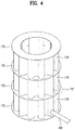
- FIG. 4 is a perspective view showing an appearance of a bellows drum 110 of the buoyant body shown in FIG. 3
- FIG. 5(a) is a main part cross-sectional view showing welding portions at the time of manufacture of the bellows drum.
- the buoyant body 100 shown in FIG. 3 includes: the bellows drum 110 having a space defined therein, the space in which the high-pressure air A and the ballast water B are contained together; a ballast water inlet/outlet 120 to which each of the ballast water flowing tubes 300 through which the ballast water B flows is connected; a high-pressure air inlet 130 having an air inlet valve mounted thereat, the air inlet valve through which the high-pressure air A is introduced from the high-pressure tank 400; the air outlet 140 having the air outlet valve mounted thereat through which the air contained in the buoyant body is discharged; a sealing plate 150 covering and sealing each upper and lower surface of the bellows drum 110; and a cover plate 160 covering the sealing plate 150 and to which each of the connecting members 200 connecting the respective buoyant bodies 100 is secured.
- the configuration and operation of the buoyant bodies 100 are described above, so a description thereof will not be repeated.
- the bellows drum 110 will be described in detail below.
- the bellows drum 100 shown in FIG. 4 is configured such that a bellows thereof is a vertical bellows having a multi-layer structure in which ridges and troughs are having vertically formed, and multiple reinforcement rings 170 are provided at regular intervals in a height direction.
- the reinforcement rings 170 and horizontal surfaces of the bellows are welded together.
- vertical bellows denotes a configuration in which each ridge and each trough are continuous vertically and have a substantially sunflower shape in a plan view.
- the bellows can be referred to as a corrugated tube, and a sectional area thereof is wider than that of a tube having no corrugation. This leads to a reduction in load per unit area, making it possible for the bellows to withstand a relatively large load.
- the system according to the present invention differs from the related art in that the high-pressure air pressure is much larger than the atmospheric pressure is used as air creating buoyancy of the buoyant body so as to reduce a difference between external water pressure and air pressure present in the buoyant body and thus reduce deformation of the buoyant body.
- a bellows shape is the most preferable in order to exert such strength by using a relatively thin steel plate.
- the vertical bellows as described above is slightly weaker to a load applied in a transverse direction in strength than a load applied in the height direction. Due to this, the ring-shaped reinforcement rings 170 are adapted to be provided on the horizontal surfaces of the bellows.
- the bellows drum 110 may be mass manufactured in a shape in which bellows tubes each having a predetermined height are manufactured and the bellows tubes are stacked on top of each other by welding together with the reinforcement rings 170 interposed therebetween.
- FIG. 5(a) is a main part cross-sectional view showing a portion A of FIG. 4 , which shows welding portions.
- FIG. 5(a) which is the cross-sectional view showing the portion A
- a cross section of the bellows tube and a reinforcement ring 170 can be welded together while being arranged in a direction perpendicular to each other.
- FIG. 6 is a perspective view showing a horizontal bellows drum 110 as compared to the vertical bellows shown in FIG. 3 .
- the horizontal bellows drum 110 shown in FIG. 6 is configured such that a bellows tube is divided into multiple bellows tubes arranged in a circumferential direction (circumferentially divided structure) unlike the vertical bellows drum 110 shown in FIG. 3 , and the bellows tubes are secured to each other by welding together with reinforcement plates 180 interposed therebetween.
- the horizontal bellows drum 110 shown in FIG. 6 is configured such that a bellows thereof is a horizontal bellows in which ridges and troughs are horizontally formed.
- the horizontal bellow drum may have high strength against the load applied in the transverse direction while having relatively low strength against the load applied in the height direction.
- the reinforcement plates 180 are adapted to reinforce the strength.
- the reinforcement plates 180 and the bellows tube are in contact with each other vertically, making it possible to facilitate welding as described above and thus to enable mass manufacturing and reduce the number of processes.
- FIG. 7 is a plan view showing a cylindrical bellows drum 110 formed by applying concrete on an outer surface of the bellows drum 110 shown in FIG. 4 .
- the buoyant body 100 is always immersed at a certain depth in seawater and thus may undergo surface corrosion due to seawater after decades of use, leading to a reduction in strength. Due to this, concrete application is adapted to prevent such surface corrosion and to replace expensive corrosion resistant paints.
- a forming agent may be applied on the outer surface of the buoyant body to finish the outer surface, thus preventing surface corrosion of the buoyant body and increasing buoyancy.
- the system according to the present invention may have various power generation facilities such as a wind power generation facility, a solar power generation facility, and the like mounted for offshore power generation.
- the power generation facility may be mounted on any one of multiple buoyant bodies as well as being mounted at a position corresponding to the center of gravity of a geometrical figure defined by lines connecting central portion of the buoyant bodies to each other.
- the ballast water may be various liquids as well as pure water.
- the positions or types of various valves may not be limited.
- the equilibrium sensor may vary in type and mounting position as long as the equilibrium sensor is a sensor which can sense equilibrium, such as a gyroscope, as well as being the three-axis acceleration sensor.
Landscapes
- Engineering & Computer Science (AREA)
- Chemical & Material Sciences (AREA)
- Combustion & Propulsion (AREA)
- Mechanical Engineering (AREA)
- Ocean & Marine Engineering (AREA)
- Sustainable Development (AREA)
- Life Sciences & Earth Sciences (AREA)
- Sustainable Energy (AREA)
- General Engineering & Computer Science (AREA)
- Architecture (AREA)
- Civil Engineering (AREA)
- Structural Engineering (AREA)
- Physics & Mathematics (AREA)
- Fluid Mechanics (AREA)
- Wind Motors (AREA)
Applications Claiming Priority (2)
| Application Number | Priority Date | Filing Date | Title |
|---|---|---|---|
| KR1020170154750A KR101840649B1 (ko) | 2017-11-20 | 2017-11-20 | 해상 발전플랫폼의 부유시스템 |
| PCT/KR2018/003959 WO2019098465A1 (fr) | 2017-11-20 | 2018-04-04 | Système flottant de plate-forme de génération d'énergie marine |
Publications (3)
| Publication Number | Publication Date |
|---|---|
| EP3511238A4 EP3511238A4 (fr) | 2019-07-17 |
| EP3511238A1 true EP3511238A1 (fr) | 2019-07-17 |
| EP3511238B1 EP3511238B1 (fr) | 2020-08-19 |
Family
ID=61900649
Family Applications (1)
| Application Number | Title | Priority Date | Filing Date |
|---|---|---|---|
| EP18799657.4A Not-in-force EP3511238B1 (fr) | 2017-11-20 | 2018-04-04 | Système flottant de plate-forme de génération d'énergie marine |
Country Status (5)
| Country | Link |
|---|---|
| US (1) | US10518849B2 (fr) |
| EP (1) | EP3511238B1 (fr) |
| KR (1) | KR101840649B1 (fr) |
| DK (1) | DK3511238T3 (fr) |
| WO (1) | WO2019098465A1 (fr) |
Families Citing this family (19)
| Publication number | Priority date | Publication date | Assignee | Title |
|---|---|---|---|---|
| US11585313B2 (en) * | 2018-10-04 | 2023-02-21 | Eiric Skaaren | Offshore power system that utilizes pressurized compressed air |
| KR102061034B1 (ko) * | 2018-12-10 | 2019-12-31 | 한국수력원자력 주식회사 | 부유안정성이 향상된 수상 태양광 발전 시스템 |
| US10526056B1 (en) * | 2019-04-29 | 2020-01-07 | Physician Electronic Network, LLC | Generation of electric power using wave motion, wind energy and solar energy |
| US11591051B1 (en) * | 2019-11-21 | 2023-02-28 | NuEnergy Partners, LP | Tendon support buoyancy system and method |
| US12049286B1 (en) * | 2019-11-21 | 2024-07-30 | NuEnergy Partners, LP | Tendon support buoyancy system and method |
| JP7617930B2 (ja) * | 2020-01-23 | 2025-01-20 | オセルギー インク | 浮体式海洋プラットフォーム |
| KR102255985B1 (ko) * | 2020-02-07 | 2021-05-25 | 울산대학교 산학협력단 | 부유식 해상풍력발전장치의 평형 조정장치 |
| KR102293272B1 (ko) * | 2020-04-14 | 2021-08-24 | 김해곤 | 다용도 승하강 수상부유 구조물 |
| KR102346699B1 (ko) * | 2020-06-26 | 2022-01-04 | 울산대학교 산학협력단 | 부유식 해상풍력발전장치 및 그 제조방법 |
| CN112693569A (zh) * | 2021-01-29 | 2021-04-23 | 明阳智慧能源集团股份公司 | 一种适用于漂浮式平台的浮筒 |
| CN113562130A (zh) * | 2021-08-24 | 2021-10-29 | 天津大学 | 一种具有高度自平衡性的浮式风机平台 |
| CN114313125B (zh) * | 2022-01-05 | 2023-06-13 | 四川宏华石油设备有限公司 | 漂浮式基础及其主动压载系统 |
| WO2024013526A1 (fr) * | 2022-07-14 | 2024-01-18 | Frano Zanki | Objet flottant insubmersible ne basculant pas sur les vagues de la mer |
| CN115748800B (zh) * | 2022-12-09 | 2023-06-20 | 北方工业大学 | 一种适用于充气模板的海上风电基础锚固装置 |
| CN115675769A (zh) * | 2022-12-30 | 2023-02-03 | 上海雄程海洋工程股份有限公司 | 坐底式可移动海上平台及其工作方法 |
| TWI863305B (zh) * | 2023-05-26 | 2024-11-21 | 向陽農業生技股份有限公司 | 漂浮載台之框體 |
| US12575517B1 (en) * | 2023-06-29 | 2026-03-17 | Clifford A. Goudey | Variable-displacement spar buoy apparatus for macroalgae farming |
| CN116853426B (zh) * | 2023-08-31 | 2023-12-08 | 山东省科学院海洋仪器仪表研究所 | 一种高稳定性深海浮标平台及其摇摆控制方法 |
| WO2026019171A1 (fr) * | 2024-07-18 | 2026-01-22 | 삼성중공업 주식회사 | Flotteur pour générateur d'énergie éolienne en mer flottant et son procédé d'assemblage |
Family Cites Families (24)
| Publication number | Priority date | Publication date | Assignee | Title |
|---|---|---|---|---|
| FR2544688B1 (fr) * | 1983-04-21 | 1986-01-17 | Arles Const Metalliques | Systeme modulaire de production, de stockage et de chargement d'hydrocarbures au large des cotes |
| US4864958A (en) * | 1987-09-25 | 1989-09-12 | Belinsky Sidney I | Swap type floating platforms |
| FI972025A7 (fi) * | 1997-05-13 | 1998-11-14 | Kvaerner Masa Yards Oy | Seinärakenne |
| US20030140838A1 (en) * | 2002-01-29 | 2003-07-31 | Horton Edward E. | Cellular SPAR apparatus and method |
| JP2005271673A (ja) * | 2004-03-24 | 2005-10-06 | Hitachi Zosen Corp | 浮体構造物における姿勢制御装置 |
| US7281483B1 (en) * | 2006-12-04 | 2007-10-16 | Agr Deepwater Development Systems, Inc | Emergency ballast system for semi-submersible drilling rigs |
| US20100150660A1 (en) * | 2007-03-12 | 2010-06-17 | Nadarajah Nagendran C | Offshore oil production platform |
| KR100939821B1 (ko) | 2007-11-30 | 2010-02-02 | 삼성중공업 주식회사 | 부유식 콘크리트 구조물의 부력 유지방법 |
| JP5022976B2 (ja) * | 2008-04-08 | 2012-09-12 | 五洋建設株式会社 | 洋上風力発電用のスパー型浮体構造およびその製造方法ならびにその設置方法 |
| KR101726988B1 (ko) | 2008-04-23 | 2017-04-14 | 프린시플 파워, 인코포레이티드 | 해안 풍력 터빈의 지지를 위한 워터-엔트랩먼트 플레이트 및 비대칭 무링 시스템을 가진 칼럼-안정화된 해안 플랫폼 |
| KR101122350B1 (ko) * | 2009-12-18 | 2012-03-23 | 에스티엑스조선해양 주식회사 | 쌍동선형 엘엔지 플로터 |
| CN103140644A (zh) * | 2010-04-15 | 2013-06-05 | 霍顿-维森深水公司 | 无条件稳定浮式海上平台 |
| US9810204B2 (en) * | 2010-10-15 | 2017-11-07 | Principle Power, Inc. | Floating wind turbine platform structure with optimized transfer of wave and wind loads |
| WO2012061562A2 (fr) * | 2010-11-03 | 2012-05-10 | Horton Wison Deepwater, Inc. | Tour offshore de forage et / ou de production |
| FR2970938A1 (fr) * | 2011-02-01 | 2012-08-03 | Technip France | Ensemble de support d'une eolienne de production d'electricite en mer |
| US20150130191A1 (en) * | 2011-05-04 | 2015-05-14 | SeaPower Systems, LLC. | Gravity-based energy-storage system and method |
| EP2807373B1 (fr) * | 2012-01-23 | 2019-03-13 | MHI Vestas Offshore Wind A/S | Commande coordonnée d'une éolienne flottante |
| ES2452933B1 (es) * | 2012-10-03 | 2015-03-09 | Tecnica Y Proyectos S A | Sistema de cimentación por gravedad para la instalación de aerogeneradores offshore |
| ES2769353T3 (es) * | 2013-05-20 | 2020-06-25 | Principle Power Inc | Sistema y procedimiento para controlar plataformas de aerogeneradores flotantes marinos |
| KR101571550B1 (ko) * | 2014-04-29 | 2015-11-24 | 삼성중공업 주식회사 | 부유식 해상 풍력발전기 |
| PT3653486T (pt) * | 2014-05-27 | 2022-01-26 | Sea Wind Towers Sl | Estrutura flutuante e método de instalação da mesma |
| US9623935B2 (en) * | 2015-07-01 | 2017-04-18 | John S. Huenefeld | Arrangement for a self-propelled watercraft supported by articulated clusters of spar buoys for the purpose of providing a mobile, wave motion-isolated, floating platform |
| KR20170032574A (ko) * | 2015-09-15 | 2017-03-23 | 삼성중공업 주식회사 | 침몰 방지구조를 갖는 선박 |
| FR3048409B1 (fr) * | 2016-03-02 | 2018-03-23 | IFP Energies Nouvelles | Systeme de stabilisation, en particulier pour un support flottant, avec au moins trois reserves de liquide reliees entre elles |
-
2017
- 2017-11-20 KR KR1020170154750A patent/KR101840649B1/ko active Active
-
2018
- 2018-04-04 DK DK18799657.4T patent/DK3511238T3/da active
- 2018-04-04 EP EP18799657.4A patent/EP3511238B1/fr not_active Not-in-force
- 2018-04-04 WO PCT/KR2018/003959 patent/WO2019098465A1/fr not_active Ceased
- 2018-11-20 US US16/196,295 patent/US10518849B2/en active Active
Also Published As
| Publication number | Publication date |
|---|---|
| WO2019098465A1 (fr) | 2019-05-23 |
| US20190152568A1 (en) | 2019-05-23 |
| EP3511238B1 (fr) | 2020-08-19 |
| US10518849B2 (en) | 2019-12-31 |
| KR101840649B1 (ko) | 2018-03-21 |
| EP3511238A4 (fr) | 2019-07-17 |
| DK3511238T3 (da) | 2020-11-16 |
Similar Documents
| Publication | Publication Date | Title |
|---|---|---|
| US10518849B2 (en) | Flotation system for offshore power generation platform | |
| US10174744B2 (en) | Semi-submersible floating wind turbine platform structure with water entrapment plates | |
| JP2005313665A (ja) | 浮体構造物の姿勢制御装置 | |
| CN101027231A (zh) | 位于海底的贮存器 | |
| CN113879474A (zh) | 半潜式海上风力发电平台及其主动浮态调节方法 | |
| CN103434616B (zh) | 一种水下浮体及其安装方法 | |
| WO2013084878A1 (fr) | Procédé de transport de pièces pour installation d'éolienne flottante | |
| CN111891306B (zh) | 模块化空间桁架结构张力腿式海上浮式平台 | |
| HK1251207A1 (en) | Floating wind turbine platform structure with optimized transfer of wave and wind loads | |
| EP4428030A1 (fr) | Borne de recharge d'hydrogène marine | |
| EP3953248B1 (fr) | Plateforme semi-submersible à colonne unique | |
| CN106677258A (zh) | 一种电厂海上取水头沉箱的安装工艺 | |
| CN111874172B (zh) | 模块化空间桁架结构全浮式海上浮式平台 | |
| KR20190096179A (ko) | 해상 발전구조물의 부유시스템 | |
| CN203372369U (zh) | 一种压力平衡式浮体 | |
| WO2024217873A1 (fr) | Plateforme de turbine éolienne semi-submersible | |
| KR20150144940A (ko) | 부유식 발전 플랜트의 평형수 탱크 | |
| KR20160085984A (ko) | 해상 구조물 계류용 장력유지장치 | |
| CN223408095U (zh) | 模块化漂浮式基础平台及漂浮式风力发电机 | |
| CN222227308U (zh) | 一种管道沉放装置 | |
| EP3333415A1 (fr) | Centrale houlomotrice à dépression | |
| JP5764673B2 (ja) | 浮体式風車設備の部品搬送方法 | |
| US20180163692A1 (en) | Negative-pressure wave generator | |
| JP4895626B2 (ja) | 液面揺動抑制装置および液面揺動抑制方法 | |
| IT202300008592A1 (it) | Piattaforma marina natante modulare senza diretto contatto con l'acqua. |
Legal Events
| Date | Code | Title | Description |
|---|---|---|---|
| STAA | Information on the status of an ep patent application or granted ep patent |
Free format text: STATUS: UNKNOWN |
|
| STAA | Information on the status of an ep patent application or granted ep patent |
Free format text: STATUS: THE INTERNATIONAL PUBLICATION HAS BEEN MADE |
|
| PUAI | Public reference made under article 153(3) epc to a published international application that has entered the european phase |
Free format text: ORIGINAL CODE: 0009012 |
|
| STAA | Information on the status of an ep patent application or granted ep patent |
Free format text: STATUS: REQUEST FOR EXAMINATION WAS MADE |
|
| 17P | Request for examination filed |
Effective date: 20181120 |
|
| A4 | Supplementary search report drawn up and despatched |
Effective date: 20190531 |
|
| AK | Designated contracting states |
Kind code of ref document: A1 Designated state(s): AL AT BE BG CH CY CZ DE DK EE ES FI FR GB GR HR HU IE IS IT LI LT LU LV MC MK MT NL NO PL PT RO RS SE SI SK SM TR |
|
| AX | Request for extension of the european patent |
Extension state: BA ME |
|
| GRAP | Despatch of communication of intention to grant a patent |
Free format text: ORIGINAL CODE: EPIDOSNIGR1 |
|
| STAA | Information on the status of an ep patent application or granted ep patent |
Free format text: STATUS: GRANT OF PATENT IS INTENDED |
|
| RIC1 | Information provided on ipc code assigned before grant |
Ipc: F03D 13/25 20160101ALI20200406BHEP Ipc: B63B 5/20 20060101ALI20200406BHEP Ipc: B63B 43/06 20060101ALI20200406BHEP Ipc: B63B 35/44 20060101AFI20200406BHEP Ipc: B63B 3/06 20060101ALI20200406BHEP |
|
| DAV | Request for validation of the european patent (deleted) | ||
| DAX | Request for extension of the european patent (deleted) | ||
| INTG | Intention to grant announced |
Effective date: 20200428 |
|
| GRAS | Grant fee paid |
Free format text: ORIGINAL CODE: EPIDOSNIGR3 |
|
| GRAA | (expected) grant |
Free format text: ORIGINAL CODE: 0009210 |
|
| STAA | Information on the status of an ep patent application or granted ep patent |
Free format text: STATUS: THE PATENT HAS BEEN GRANTED |
|
| AK | Designated contracting states |
Kind code of ref document: B1 Designated state(s): AL AT BE BG CH CY CZ DE DK EE ES FI FR GB GR HR HU IE IS IT LI LT LU LV MC MK MT NL NO PL PT RO RS SE SI SK SM TR |
|
| REG | Reference to a national code |
Ref country code: CH Ref legal event code: EP |
|
| REG | Reference to a national code |
Ref country code: DE Ref legal event code: R096 Ref document number: 602018007139 Country of ref document: DE |
|
| REG | Reference to a national code |
Ref country code: AT Ref legal event code: REF Ref document number: 1303657 Country of ref document: AT Kind code of ref document: T Effective date: 20200915 |
|
| REG | Reference to a national code |
Ref country code: IE Ref legal event code: FG4D |
|
| REG | Reference to a national code |
Ref country code: NO Ref legal event code: T2 Effective date: 20200819 |
|
| REG | Reference to a national code |
Ref country code: DK Ref legal event code: T3 Effective date: 20201110 |
|
| REG | Reference to a national code |
Ref country code: LT Ref legal event code: MG4D |
|
| REG | Reference to a national code |
Ref country code: NL Ref legal event code: MP Effective date: 20200819 |
|
| PG25 | Lapsed in a contracting state [announced via postgrant information from national office to epo] |
Ref country code: FI Free format text: LAPSE BECAUSE OF FAILURE TO SUBMIT A TRANSLATION OF THE DESCRIPTION OR TO PAY THE FEE WITHIN THE PRESCRIBED TIME-LIMIT Effective date: 20200819 Ref country code: PT Free format text: LAPSE BECAUSE OF FAILURE TO SUBMIT A TRANSLATION OF THE DESCRIPTION OR TO PAY THE FEE WITHIN THE PRESCRIBED TIME-LIMIT Effective date: 20201221 Ref country code: SE Free format text: LAPSE BECAUSE OF FAILURE TO SUBMIT A TRANSLATION OF THE DESCRIPTION OR TO PAY THE FEE WITHIN THE PRESCRIBED TIME-LIMIT Effective date: 20200819 Ref country code: BG Free format text: LAPSE BECAUSE OF FAILURE TO SUBMIT A TRANSLATION OF THE DESCRIPTION OR TO PAY THE FEE WITHIN THE PRESCRIBED TIME-LIMIT Effective date: 20201119 Ref country code: LT Free format text: LAPSE BECAUSE OF FAILURE TO SUBMIT A TRANSLATION OF THE DESCRIPTION OR TO PAY THE FEE WITHIN THE PRESCRIBED TIME-LIMIT Effective date: 20200819 Ref country code: HR Free format text: LAPSE BECAUSE OF FAILURE TO SUBMIT A TRANSLATION OF THE DESCRIPTION OR TO PAY THE FEE WITHIN THE PRESCRIBED TIME-LIMIT Effective date: 20200819 Ref country code: GR Free format text: LAPSE BECAUSE OF FAILURE TO SUBMIT A TRANSLATION OF THE DESCRIPTION OR TO PAY THE FEE WITHIN THE PRESCRIBED TIME-LIMIT Effective date: 20201120 |
|
| REG | Reference to a national code |
Ref country code: AT Ref legal event code: MK05 Ref document number: 1303657 Country of ref document: AT Kind code of ref document: T Effective date: 20200819 |
|
| PG25 | Lapsed in a contracting state [announced via postgrant information from national office to epo] |
Ref country code: LV Free format text: LAPSE BECAUSE OF FAILURE TO SUBMIT A TRANSLATION OF THE DESCRIPTION OR TO PAY THE FEE WITHIN THE PRESCRIBED TIME-LIMIT Effective date: 20200819 Ref country code: PL Free format text: LAPSE BECAUSE OF FAILURE TO SUBMIT A TRANSLATION OF THE DESCRIPTION OR TO PAY THE FEE WITHIN THE PRESCRIBED TIME-LIMIT Effective date: 20200819 Ref country code: NL Free format text: LAPSE BECAUSE OF FAILURE TO SUBMIT A TRANSLATION OF THE DESCRIPTION OR TO PAY THE FEE WITHIN THE PRESCRIBED TIME-LIMIT Effective date: 20200819 Ref country code: RS Free format text: LAPSE BECAUSE OF FAILURE TO SUBMIT A TRANSLATION OF THE DESCRIPTION OR TO PAY THE FEE WITHIN THE PRESCRIBED TIME-LIMIT Effective date: 20200819 Ref country code: IS Free format text: LAPSE BECAUSE OF FAILURE TO SUBMIT A TRANSLATION OF THE DESCRIPTION OR TO PAY THE FEE WITHIN THE PRESCRIBED TIME-LIMIT Effective date: 20201219 |
|
| PG25 | Lapsed in a contracting state [announced via postgrant information from national office to epo] |
Ref country code: RO Free format text: LAPSE BECAUSE OF FAILURE TO SUBMIT A TRANSLATION OF THE DESCRIPTION OR TO PAY THE FEE WITHIN THE PRESCRIBED TIME-LIMIT Effective date: 20200819 Ref country code: CZ Free format text: LAPSE BECAUSE OF FAILURE TO SUBMIT A TRANSLATION OF THE DESCRIPTION OR TO PAY THE FEE WITHIN THE PRESCRIBED TIME-LIMIT Effective date: 20200819 Ref country code: EE Free format text: LAPSE BECAUSE OF FAILURE TO SUBMIT A TRANSLATION OF THE DESCRIPTION OR TO PAY THE FEE WITHIN THE PRESCRIBED TIME-LIMIT Effective date: 20200819 Ref country code: SM Free format text: LAPSE BECAUSE OF FAILURE TO SUBMIT A TRANSLATION OF THE DESCRIPTION OR TO PAY THE FEE WITHIN THE PRESCRIBED TIME-LIMIT Effective date: 20200819 |
|
| REG | Reference to a national code |
Ref country code: DE Ref legal event code: R097 Ref document number: 602018007139 Country of ref document: DE |
|
| PG25 | Lapsed in a contracting state [announced via postgrant information from national office to epo] |
Ref country code: AL Free format text: LAPSE BECAUSE OF FAILURE TO SUBMIT A TRANSLATION OF THE DESCRIPTION OR TO PAY THE FEE WITHIN THE PRESCRIBED TIME-LIMIT Effective date: 20200819 Ref country code: AT Free format text: LAPSE BECAUSE OF FAILURE TO SUBMIT A TRANSLATION OF THE DESCRIPTION OR TO PAY THE FEE WITHIN THE PRESCRIBED TIME-LIMIT Effective date: 20200819 Ref country code: ES Free format text: LAPSE BECAUSE OF FAILURE TO SUBMIT A TRANSLATION OF THE DESCRIPTION OR TO PAY THE FEE WITHIN THE PRESCRIBED TIME-LIMIT Effective date: 20200819 |
|
| PLBE | No opposition filed within time limit |
Free format text: ORIGINAL CODE: 0009261 |
|
| STAA | Information on the status of an ep patent application or granted ep patent |
Free format text: STATUS: NO OPPOSITION FILED WITHIN TIME LIMIT |
|
| PG25 | Lapsed in a contracting state [announced via postgrant information from national office to epo] |
Ref country code: SK Free format text: LAPSE BECAUSE OF FAILURE TO SUBMIT A TRANSLATION OF THE DESCRIPTION OR TO PAY THE FEE WITHIN THE PRESCRIBED TIME-LIMIT Effective date: 20200819 |
|
| 26N | No opposition filed |
Effective date: 20210520 |
|
| PG25 | Lapsed in a contracting state [announced via postgrant information from national office to epo] |
Ref country code: IT Free format text: LAPSE BECAUSE OF FAILURE TO SUBMIT A TRANSLATION OF THE DESCRIPTION OR TO PAY THE FEE WITHIN THE PRESCRIBED TIME-LIMIT Effective date: 20200819 |
|
| PG25 | Lapsed in a contracting state [announced via postgrant information from national office to epo] |
Ref country code: SI Free format text: LAPSE BECAUSE OF FAILURE TO SUBMIT A TRANSLATION OF THE DESCRIPTION OR TO PAY THE FEE WITHIN THE PRESCRIBED TIME-LIMIT Effective date: 20200819 |
|
| PG25 | Lapsed in a contracting state [announced via postgrant information from national office to epo] |
Ref country code: MC Free format text: LAPSE BECAUSE OF FAILURE TO SUBMIT A TRANSLATION OF THE DESCRIPTION OR TO PAY THE FEE WITHIN THE PRESCRIBED TIME-LIMIT Effective date: 20200819 |
|
| PG25 | Lapsed in a contracting state [announced via postgrant information from national office to epo] |
Ref country code: LU Free format text: LAPSE BECAUSE OF NON-PAYMENT OF DUE FEES Effective date: 20210404 |
|
| REG | Reference to a national code |
Ref country code: BE Ref legal event code: MM Effective date: 20210430 |
|
| PG25 | Lapsed in a contracting state [announced via postgrant information from national office to epo] |
Ref country code: LI Free format text: LAPSE BECAUSE OF NON-PAYMENT OF DUE FEES Effective date: 20210430 Ref country code: CH Free format text: LAPSE BECAUSE OF NON-PAYMENT OF DUE FEES Effective date: 20210430 |
|
| PG25 | Lapsed in a contracting state [announced via postgrant information from national office to epo] |
Ref country code: IE Free format text: LAPSE BECAUSE OF NON-PAYMENT OF DUE FEES Effective date: 20210404 |
|
| PG25 | Lapsed in a contracting state [announced via postgrant information from national office to epo] |
Ref country code: IS Free format text: LAPSE BECAUSE OF FAILURE TO SUBMIT A TRANSLATION OF THE DESCRIPTION OR TO PAY THE FEE WITHIN THE PRESCRIBED TIME-LIMIT Effective date: 20201219 |
|
| PG25 | Lapsed in a contracting state [announced via postgrant information from national office to epo] |
Ref country code: BE Free format text: LAPSE BECAUSE OF NON-PAYMENT OF DUE FEES Effective date: 20210430 |
|
| PG25 | Lapsed in a contracting state [announced via postgrant information from national office to epo] |
Ref country code: CY Free format text: LAPSE BECAUSE OF FAILURE TO SUBMIT A TRANSLATION OF THE DESCRIPTION OR TO PAY THE FEE WITHIN THE PRESCRIBED TIME-LIMIT Effective date: 20200819 |
|
| PG25 | Lapsed in a contracting state [announced via postgrant information from national office to epo] |
Ref country code: HU Free format text: LAPSE BECAUSE OF FAILURE TO SUBMIT A TRANSLATION OF THE DESCRIPTION OR TO PAY THE FEE WITHIN THE PRESCRIBED TIME-LIMIT; INVALID AB INITIO Effective date: 20180404 |
|
| PG25 | Lapsed in a contracting state [announced via postgrant information from national office to epo] |
Ref country code: MK Free format text: LAPSE BECAUSE OF FAILURE TO SUBMIT A TRANSLATION OF THE DESCRIPTION OR TO PAY THE FEE WITHIN THE PRESCRIBED TIME-LIMIT Effective date: 20200819 |
|
| PGFP | Annual fee paid to national office [announced via postgrant information from national office to epo] |
Ref country code: GB Payment date: 20240419 Year of fee payment: 7 |
|
| PGFP | Annual fee paid to national office [announced via postgrant information from national office to epo] |
Ref country code: DE Payment date: 20240415 Year of fee payment: 7 |
|
| PGFP | Annual fee paid to national office [announced via postgrant information from national office to epo] |
Ref country code: DK Payment date: 20240418 Year of fee payment: 7 |
|
| PGFP | Annual fee paid to national office [announced via postgrant information from national office to epo] |
Ref country code: NO Payment date: 20240419 Year of fee payment: 7 Ref country code: FR Payment date: 20240418 Year of fee payment: 7 |
|
| PG25 | Lapsed in a contracting state [announced via postgrant information from national office to epo] |
Ref country code: MT Free format text: LAPSE BECAUSE OF FAILURE TO SUBMIT A TRANSLATION OF THE DESCRIPTION OR TO PAY THE FEE WITHIN THE PRESCRIBED TIME-LIMIT Effective date: 20200819 |
|
| REG | Reference to a national code |
Ref country code: DE Ref legal event code: R119 Ref document number: 602018007139 Country of ref document: DE |
|
| REG | Reference to a national code |
Ref country code: DK Ref legal event code: EBP Effective date: 20250430 |
|
| PG25 | Lapsed in a contracting state [announced via postgrant information from national office to epo] |
Ref country code: TR Free format text: LAPSE BECAUSE OF FAILURE TO SUBMIT A TRANSLATION OF THE DESCRIPTION OR TO PAY THE FEE WITHIN THE PRESCRIBED TIME-LIMIT Effective date: 20200819 |
|
| GBPC | Gb: european patent ceased through non-payment of renewal fee |
Effective date: 20250404 |
|
| PG25 | Lapsed in a contracting state [announced via postgrant information from national office to epo] |
Ref country code: DE Free format text: LAPSE BECAUSE OF NON-PAYMENT OF DUE FEES Effective date: 20251104 |
|
| PG25 | Lapsed in a contracting state [announced via postgrant information from national office to epo] |
Ref country code: GB Free format text: LAPSE BECAUSE OF NON-PAYMENT OF DUE FEES Effective date: 20250404 |
|
| PG25 | Lapsed in a contracting state [announced via postgrant information from national office to epo] |
Ref country code: NO Free format text: LAPSE BECAUSE OF NON-PAYMENT OF DUE FEES Effective date: 20250430 |
|
| PG25 | Lapsed in a contracting state [announced via postgrant information from national office to epo] |
Ref country code: FR Free format text: LAPSE BECAUSE OF NON-PAYMENT OF DUE FEES Effective date: 20250430 |
|
| PG25 | Lapsed in a contracting state [announced via postgrant information from national office to epo] |
Ref country code: DK Free format text: LAPSE BECAUSE OF NON-PAYMENT OF DUE FEES Effective date: 20250430 |