EP3511280B1 - Opération de secours dans un système d'ascenseur - Google Patents
Opération de secours dans un système d'ascenseur Download PDFInfo
- Publication number
- EP3511280B1 EP3511280B1 EP18151282.3A EP18151282A EP3511280B1 EP 3511280 B1 EP3511280 B1 EP 3511280B1 EP 18151282 A EP18151282 A EP 18151282A EP 3511280 B1 EP3511280 B1 EP 3511280B1
- Authority
- EP
- European Patent Office
- Prior art keywords
- elevator
- elevator car
- service center
- remote service
- remote
- Prior art date
- Legal status (The legal status is an assumption and is not a legal conclusion. Google has not performed a legal analysis and makes no representation as to the accuracy of the status listed.)
- Active
Links
Images

Classifications
-
- B—PERFORMING OPERATIONS; TRANSPORTING
- B66—HOISTING; LIFTING; HAULING
- B66B—ELEVATORS; ESCALATORS OR MOVING WALKWAYS
- B66B5/00—Applications of checking, fault-correcting, or safety devices in elevators
- B66B5/02—Applications of checking, fault-correcting, or safety devices in elevators responsive to abnormal operating conditions
- B66B5/027—Applications of checking, fault-correcting, or safety devices in elevators responsive to abnormal operating conditions to permit passengers to leave an elevator car in case of failure, e.g. moving the car to a reference floor or unlocking the door
-
- B—PERFORMING OPERATIONS; TRANSPORTING
- B66—HOISTING; LIFTING; HAULING
- B66B—ELEVATORS; ESCALATORS OR MOVING WALKWAYS
- B66B1/00—Control systems of elevators in general
- B66B1/02—Control systems without regulation, i.e. without retroactive action
- B66B1/06—Control systems without regulation, i.e. without retroactive action electric
-
- B—PERFORMING OPERATIONS; TRANSPORTING
- B66—HOISTING; LIFTING; HAULING
- B66B—ELEVATORS; ESCALATORS OR MOVING WALKWAYS
- B66B1/00—Control systems of elevators in general
- B66B1/34—Details, e.g. call counting devices, data transmission from car to control system, devices giving information to the control system
- B66B1/3415—Control system configuration and the data transmission or communication within the control system
- B66B1/3423—Control system configuration, i.e. lay-out
-
- B—PERFORMING OPERATIONS; TRANSPORTING
- B66—HOISTING; LIFTING; HAULING
- B66B—ELEVATORS; ESCALATORS OR MOVING WALKWAYS
- B66B1/00—Control systems of elevators in general
- B66B1/34—Details, e.g. call counting devices, data transmission from car to control system, devices giving information to the control system
- B66B1/3415—Control system configuration and the data transmission or communication within the control system
- B66B1/3446—Data transmission or communication within the control system
- B66B1/3461—Data transmission or communication within the control system between the elevator control system and remote or mobile stations
-
- B—PERFORMING OPERATIONS; TRANSPORTING
- B66—HOISTING; LIFTING; HAULING
- B66B—ELEVATORS; ESCALATORS OR MOVING WALKWAYS
- B66B5/00—Applications of checking, fault-correcting, or safety devices in elevators
- B66B5/0006—Monitoring devices or performance analysers
-
- B—PERFORMING OPERATIONS; TRANSPORTING
- B66—HOISTING; LIFTING; HAULING
- B66B—ELEVATORS; ESCALATORS OR MOVING WALKWAYS
- B66B5/00—Applications of checking, fault-correcting, or safety devices in elevators
- B66B5/0006—Monitoring devices or performance analysers
- B66B5/0018—Devices monitoring the operating condition of the elevator system
-
- B—PERFORMING OPERATIONS; TRANSPORTING
- B66—HOISTING; LIFTING; HAULING
- B66B—ELEVATORS; ESCALATORS OR MOVING WALKWAYS
- B66B5/00—Applications of checking, fault-correcting, or safety devices in elevators
- B66B5/0006—Monitoring devices or performance analysers
- B66B5/0018—Devices monitoring the operating condition of the elevator system
- B66B5/0031—Devices monitoring the operating condition of the elevator system for safety reasons
-
- B—PERFORMING OPERATIONS; TRANSPORTING
- B66—HOISTING; LIFTING; HAULING
- B66B—ELEVATORS; ESCALATORS OR MOVING WALKWAYS
- B66B3/00—Applications of devices for indicating or signalling operating conditions of elevators
- B66B3/002—Indicators
Definitions
- the invention relates to a rescue operation for an elevator system and to an elevator system configured for performing such a rescue operation.
- An elevator system comprises at least one elevator car traveling along a hoistway between a plurality of landings.
- the elevator car may be stopped at a position within the hoistway between the landings.
- passengers may be trapped within the elevator car.
- a qualified mechanic has to visit the site for operating the elevator system in a manual emergency rescue operation in order to free the passengers. Waiting to be released from the elevator car is unpleasant for the passengers trapped within the elevator car.
- US 2007/0261924 A1 discloses a method and a system for executing elevator control actions from a remote terminal in a remote control system.
- a method of performing a rescue operation in an elevator system comprises establishing a data connection between the elevator system and a remote service center and sending an alarm message indicating a malfunction of the elevator system from the elevator system to the remote service center.
- the remote service center requests allowance from the elevator system for performing a remote manual rescue operation.
- the elevator system requests authentication from the remote service center to be allowed initiating an emergency rescue operation.
- a remote manual emergency rescue operation is initiated by the operator at the remote service center via the data connection.
- Performing the remote manual emergency rescue operation includes moving the elevator car over a predetermined distance and/or for a predetermined period of time along the hoistway after a control signal has been received, and stopping the elevator car unless a further control signal indicating to continue moving the elevator car is received via the data connection before the elevator car has been stopped.
- a further control signal indicating to continue moving the elevator car is received via the data connection before the elevator car has been stopped.
- a remote hold signal is issued by the operator and transmitted to the elevator control.
- the remote hold signal need to be generated completely independently of the remote control signal. As long as the remote hold signal is received by the elevator control, the elevator car is moved in correspondence with remote control signal. Once the remote hold signal is no longer received, the elevator control stops the elevator car and does no longer react to the remote control signal. Thus, the remote control signal is not effective anymore.
- Embodiments of the invention further include an elevator system according to claim 9, comprising an elevator car configured for moving along a hoistway, an elevator control configured for controlling the movement of the elevator car, and a communication circuit configured for establishing a data connection between the elevator system and a remote service center.
- the elevator control includes a safety circuit configured for detecting a malfunction of the elevator system.
- the elevator control is configured for sending an alarm message indicating a malfunction of the elevator system via the communication circuit to the remote service center; receiving a request for initiating a manual emergency rescue operation via the communication circuit; checking whether the remote service center and/or an operator at the remote service center is allowed initiating an emergency rescue operation; and initiating a manual emergency rescue operation after a request for initiating a manual emergency rescue operation has been received and the remote service center and/or the operator at the remote service center have been confirmed as being allowed initiating an emergency rescue operation.
- the manual emergency rescue operation in particular may include moving the elevator car along the hoistway to a landing and opening at least one hoistway door and at least one door of the elevator car after the elevator car has been stopped at the landing. This allows passengers trapped within the elevator car to leave the elevator car via the at least one hoistway door.
- Exemplary embodiments of the invention allow an operator at a remote service center to initiate and perform a manual emergency rescue operation in order to free passengers trapped within an elevator car in case of a malfunction of the elevator system. Since there is no need to wait for a mechanic to visit the elevator system in order to initiate and perform the manual emergency rescue operation, the time the passengers have to wait to be released from the elevator car may be considerably reduced. Further, the costs for sending a mechanic to the elevator system in an emergency situation may be saved. A specific authentication procedure is carried out in order to ensure that the remote manual emergency rescue operation is carried out only by authorized and qualified persons.
- the method may include sending status information from the elevator system to the remote service center in addition to the alarm message.
- Said status information may help the operator at the remote service center to determine the cause of the malfunction in order to initiate appropriate countermeasures. It in particular may help the operator to decide whether a remote manual emergency rescue operation can be performed or whether it is necessary to send a mechanic to the elevator system in order to release the passengers from the elevator car.
- the status information from the elevator system obtained by the remote service center may be used by the remote service person to ensure that executing a remote manual rescue operation is safe, e.g. to make sure that there are no persons in the hoistway.
- the additional status information may further help determining which tools and/or spare parts are needed for solving the problem. This may facilitate and speed up the repair process.
- the additional status information may include pictures from at least a portion of the hoistway above and/or below the elevator car.
- the elevator system may comprise at least one camera configured for taking pictures from inside the hoistway.
- the communication circuit may be configured for sending the pictures recorded by the at least one camera via the data connection to the remote service center.
- the at least one camera in particular may be configured for providing real time pictures.
- the at least one camera may provide moving (video) pictures.
- Such moving pictures may be transferred to the remote service center in real time, at least after the alarm message indicating a malfunction has been sent to the remote service center and/or has been received by the remote service center.
- it may be sufficient for the camera to provide still pictures given the camera is able to produce a series of still pictures with sufficient temporal resolution to allow a real time evaluation of the current situation in the hoistway.
- the elevator system may further comprise at least one illumination device configured for illuminating at least a portion of the hoistway.
- the elevator control may be configured to switch on the at least one illumination device when a malfunction has been detected and/or when the at least one camera is activated. Illuminating at least a portion of the hoistway may increase the quality of the pictures recorded by the at least one camera.
- Evaluating pictures from at least a portion of the hoistway above and/or below the elevator car allows the operator in the remote service center to determine whether the space above and/or below the elevator car is empty, or whether there is a person or an obstacle above and/or below the elevator car.
- the pictures allow the operator to decide whether it is safe to move the elevator car in a remote emergency rescue operation or whether it is necessary to send a mechanic to the elevator system, e.g. in order to remove an obstacle from the hoistway before the elevator car may be moved.
- An audio connection may be established between the remote service center and the elevator car in order to allow the operator at the remote service center to communicate with passengers trapped within the elevator car.
- the method may include checking the integrity of the elevator system in order to determine whether the issue, which caused the malfunction, still exists, and to instruct the elevator system to resume normal operation when it is determined that the problem has been solved.
- the integrity check may be carried out once the elevator car has reached a safe landing at the end of the remote manual emergency rescue operation.
- This integrity check procedure may particularly include rebooting the elevator control, e.g. as a final step in case no malfunction has been detected in the integrity check, or as a first step after the elevator car has reached a safe landing, followed by suitable integrity check procedures.
- rebooting the elevator control e.g. as a final step in case no malfunction has been detected in the integrity check, or as a first step after the elevator car has reached a safe landing, followed by suitable integrity check procedures.
- the elevator system may be shut down, and a mechanic may be instructed to visit the elevator system in order to solve the problem.
- the communication circuit may provide additional information to the remote service center. Based on the additional information provided by the communication circuit, the mechanic may take tools and/or spare parts needed for solving the problem with him in order to facilitate and speed up the repair process.
- Authenticating the remote service center and/or the operator may include using an asymmetric encryption mechanism employing a public key and a corresponding private key.
- the elevator control may comprise a decryption circuit, which is configured for decrypting and/or authenticating messages received from the remote service center.
- the decryption circuit in particular may be configured for executing an asymmetric encryption mechanism.
- An asymmetric encryption mechanism allows for a reliable and safe authentication.
- the decryption circuit may comprise a chip, in particular a smart card chip, storing a key, which is needed for encrypting and/or decrypting the messages.
- the chip may be soldered directly on a printed circuit board (PCB).
- the decryption circuit may comprise a smart card reader for reading a key stored on a smart card which is inserted into the smart card reader.
- a smart card reader allows providing the key needed for encrypting and/or decrypting the messages conveniently via smart card. In such a configuration, the key may be changed easily by replacing the smart card.
- the data connection between the elevator system and the remote service center may be established via the Internet, in particular via a virtual private network (VPN) and/or via a virtual cloud established within the Internet.
- the Internet allows for a reliable date connection, which is easy to implement and which allows for the transfer of large amounts of data at low costs. Sending the data via a virtual private network and/or via a virtual cloud reliably prevents unauthorized access to the data.
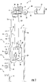
- Figure 1 schematically depicts an elevator system 2 configured for performing a remote manual emergency rescue operation according to an exemplary embodiment of the invention.
- the elevator system 2 comprises an elevator car 6 which is movably suspended within a hoistway 4 extending between a plurality of landings 8 located on different floors.
- the elevator car 6 is movably suspended by means of a tension member 3.
- the tension member 3 for example a rope or belt, is connected to a drive 5, which is configured for driving the tension member 3 in order to move the elevator car 6 along the height of the hoistway 4 between the plurality of landings 8.
- Each landing 8 is provided with an elevator hoistway door (landing door) 10, and the elevator car 6 is provided with an elevator car door 11 allowing passengers 29 to transfer between a landing 8 and the interior of the elevator car 6 when the elevator car 6 is positioned at the respective landing 8.
- the exemplary embodiment of the elevator system 2 shown in Fig. 1 employs a 1:1 roping for suspending the elevator car 6.
- the skilled person easily understands that the type of the roping is not essential for the invention and that different kinds of roping, e.g. a 2:1 roping, may be used as well.
- the elevator system 2 may further include a counterweight (not shown) moving concurrently and in opposite direction with respect to the elevator car 6.
- the elevator system 2 may be an elevator system 2 without a counterweight, as it is shown in Fig. 1 .
- the drive 5 may be any form of drive used in the art, e.g. a traction drive, a hydraulic drive or a linear drive.
- the elevator system 2 may have a machine room or may be a machine room-less elevator system.
- the elevator system 2 may use a tension member 3, as it is shown in Figure 1 , or it may be an elevator system without a tension member 3, comprising e.g. a hydraulic drive or a linear drive (not shown).
- the drive 5 is controlled by an elevator control 13 for moving the elevator car 6 along the hoistway 4 between the different landings 8.
- the elevator control 13 comprises a safety circuit 17, which is configured for monitoring the safety of the elevator system 2.
- the safety circuit 17 in particular may be connected to a safety chain (not shown) comprising a plurality of safety sensor and/or safety switches. In case one of the safety sensors, and/or its corresponding safety switch, indicates an abnormal condition, the respective safety switch will open the safety chain resulting in detection of an emergency situation by the safety circuit 17.
- Input to the elevator control 13 may be provided via landing control panels 7a, which are provided on each landing 8 close to the elevator hoistway doors 10, and/or via a car operation panel 7b provided inside the elevator car 6.
- the landing control panels 7a and the car operation panel 7b may be connected to the elevator control 13 by means of electrical lines, which are not shown in Figure 1 , in particular by an electric bus, e.g. a field bus such as a CAN bus, or by means of wireless data connections.
- an electric bus e.g. a field bus such as a CAN bus
- wireless data connections e.g.
- the elevator system 2 is provided with at least one position sensor 25 configured for detecting the current position (height) of the elevator car 6 within the hoistway 4.
- the position sensor 25 is connected with the elevator control 13 via a signal line 23, or via a wireless connection configured for transmitting the detected position of the elevator car 6 to the elevator control 13.
- a communication circuit 18 provided within, or connected with, the elevator control 13 establishes a data connection 20 between the elevator control 13 and a remote service center 22.
- the data connection 20 between the elevator system 2 and the remote service center 22 may be established via the Internet 30, in particular via a virtual private network (VPN) and/or via a virtual cloud 32 within the Internet.
- the data connection 20 may include a conventional telephone line or a digital line such as ISDN or DSL. It further may include wireless communication including WLAN, GMS, UMTS, LTE, Bluetooth ® etc.
- an alarm message is transmitted from the elevator control 13 via the communication circuit 18 and the data connection 20 to the remote service center 22 (step 110).
- An operator (technical expert) 27 at the remote service center 22 is made aware of the malfunction the elevator system 2 (step 120), e.g. by an optical and/or acoustical signal.
- the operator 27 may request further details of the current status of the elevator system 2 (step 130), which are provided via the communication circuit 18 and the data connection 20 (step 140).
- an audio connection may be established between the remote service center 22 and the elevator car 6 in order to allow the operator 27 at the remote service center 22 to communicate with passengers 29 trapped within the elevator car 6.
- step 150 Upon request from the operator 27 (step 150), pictures from inside the hoistway 4 recorded by cameras 12 arranged on top and/or below the elevator car 6 (see Fig. 1 ) are transmitted to the remote service center 22 (step 160) and displayed to the operator 27.
- the cameras 12 in particular may be configured for providing real time pictures.
- the cameras 12 may provide moving pictures. Such moving pictures may be transferred to the remote service center 22 in real time, at least after the alarm message indicating a malfunction has been sent to the remote service center 22 and/or has been received by the remote service center 22. In some embodiments, it may be sufficient that the cameras 12 provide still pictures given the cameras 12 are able to produce a series of still pictures with sufficient temporal resolution to allow a real time evaluation of the current situation in the hoistway 4.
- the cameras 12 may be attached to the elevator car 6 and/or to the walls 15 of the hoistway 4.
- the cameras 12 may be connected to the elevator control 13 by a camera signal line 16, by the signal line 23 extending between the elevator car 6 and the elevator control 13, or by means of a wireless connection, respectively.
- At least one light source 26, which may be mounted to a wall 15 of the hoistway 4 or to the elevator car 6, may be switched on for illuminating at least a portion of the hoistway 4. Illuminating at least a portion of the hoistway 4 allows the cameras 12 to record pictures of the interior of the hoistway 4 with good quality.
- the pictures displayed to the operator 27 at the remote service center 22 allow the operator 27 to reliably determine whether the space above and/or below the elevator car 6 is empty, or whether there is a person or an obstacle above and/or below the elevator car 6.
- the operator 27 may decide to move the elevator car 6 in a remote manual emergency rescue operation (ERO) in order to free passengers 29 trapped within the elevator car 6 (step 170).
- ERO remote manual emergency rescue operation
- step 180 In case the operator decides for moving the elevator car 6 in an remote manual ERO, he sends a request for allowance to perform a remote manual ERO from the remote service center 22 to the elevator control 13 (step 180).
- the elevator control 13 responds with a request for authentication to the remote service center 22 (step 190).
- the remote service center 22 and/or the operator 27 authenticates itself/himself as being authorized for initiating a remote manual ERO, for example by sending an encrypted message to the elevator control 13 which identifies the remote service center 22 and/or an operator 27 as being authorized for performing a remote manual ERO (step 200).
- the elevator control 13 is provided with a decryption circuit 19 which is configured for decrypting the encrypted message received from the remote service center 22 and for checking the authorization of the remote service center 22 and/or operator 27.
- the encrypted message in particular may be encrypted using a secret (private) key associated with the remote service center 22 and/or operator 27. Further, the encrypted message may be decrypted by a corresponding public key stored within the elevator control 13. For additional safety, the encrypted message additionally may be encrypted using a public key of the elevator control 13 and it may be decrypted with a corresponding private key stored within the elevator control 13.
- the decryption circuit 19 may comprise a chip 34, in particular a smart card chip, storing a key, which is needed for encrypting and/or decrypting the messages.
- the chip 34 may be soldered directly on a printed circuit board (PCB) of the decryption circuit 19.
- the decryption circuit 19 may comprise a smart card reader 36 configured for reading an encryption key stored on a smart card which is inserted into the smart card reader 36.
- a smart card reader 36 allows providing the key needed for encrypting and/or decrypting the messages conveniently via smart card. In such a configuration, the key may be changed easily by replacing the smart card.
- the elevator control 13 switches to the emergency rescue mode (ERO) (step 201) and sends a corresponding message to the remote service center 22 confirming that the ERO has been initiated (step 205).
- ERO emergency rescue mode
- the elevator drive 5 is controlled manually.
- a specific ERO control panel (not shown) provided at the elevator system 2 is used for controlling the elevator car 6 manually to move to a safe landing 8.
- the elevator drive 5 is controlled remotely from the remote service center 22 by sending appropriate commands from the remote service center 22 via the data connection 12 to the elevator control 13.
- the operator 27 controls the elevator drive 5 to move the elevator car 6 upwards or downwards towards a landing 8 by sending appropriate control signals via the data connection 20 (step 210).
- the elevator control 13 continuously sends feedback signals indicating the current position of the elevator car 6 within the hoistway 4 (step 220).
- the elevator car 6 moves only over a predetermined distance D, particularly 10 mm ⁇ D ⁇ 500 mm, more particularly 50 mm ⁇ D ⁇ 250 mm, or over a predetermined time period T, particularly 0,5 s ⁇ T ⁇ 3 s, more particularly 1 s ⁇ T ⁇ 2 s after a remote control signal as been issued by the operator 27.
- a new remote control signal (step 210) has to be sent to the elevator control 13.
- a series of control signals has to be issued.
- a remote hold signal may be transmitted to the elevator control 13 in addition to the remote control signal.
- a remote hold signal is generated completely independently of the remote control signal. As long as the remote hold signal is received by the elevator control 13, the elevator car 6 is moved in correspondence with the remote control signal. Once the remote hold signal is no longer received, the elevator control 13 stops the elevator car 6 and does no longer react to the remote control signal. Thus, the remote control signal is not effective anymore.
- control signals can be transmitted from the remote service center 22 to the elevator control 13 only as long as the data connection 20 is intact, the elevator car 6 stops in case the data connection 20 is interrupted. As a result, an uncontrolled movement of the elevator car 6 is prevented even in case the data connection 20 might be interrupted.
- the operator 27 opens the respective hoistway door 10 and the elevator car door 11 (step 230) in order to allow passengers 29 trapped within the elevator car 6 to leave the elevator car 6.
- the opening of the doors 10, 11 is confirmed by a corresponding message sent from the elevator control 13 to the remote service center 22 (step 240).
- the operator 27 may trigger the safety circuit 17 to check the integrity of the elevator system 2 (step 250) in order to determine whether the issue which has caused the malfunction and the alarm message still exists, or whether the problem has been solved by manually moving the elevator car 6. This check may include rebooting the elevator control 13.
- the operator 27 may terminate the remote manual ERO and instruct the elevator system 2 to resume normal operation (step 270).
- the operator 27 may shut down the elevator system 2 and instruct a mechanic to visit the elevator system 2 in order to solve the problem on site. Based on the information provided by the communication circuit 18, the mechanic may take the tools and/or spare parts needed for solving the problem with him in order to facilitate and speed up the repair process.
Landscapes
- Engineering & Computer Science (AREA)
- Automation & Control Theory (AREA)
- Computer Networks & Wireless Communication (AREA)
- Indicating And Signalling Devices For Elevators (AREA)
- Maintenance And Inspection Apparatuses For Elevators (AREA)
- Structural Engineering (AREA)
Claims (13)
- Procédé d'exécution d'une opération de sauvetage dans un système d'ascenseur (2) comprenant une cabine d'ascenseur (6) se déplaçant le long d'une cage d'ascenseur (4), dans lequel le procédé comprend :l'établissement d'une connexion de données (20) entre le système d'ascenseur (2) et un centre de service à distance (22), et l'envoi d'un message d'alarme indiquant un dysfonctionnement du système d'ascenseur (2) depuis le système d'ascenseur (2) vers le centre de service à distance (22) ;le centre de service à distance (22) demandant une autorisation au système d'ascenseur (2) pour effectuer une opération de sauvetage manuelle à distance ;le système d'ascenseur (2) demandant une authentification au centre de service à distance (22) ;l'authentification du centre de service à distance (22) et/ou d'un opérateur (27) au niveau du centre de service à distance (22) comme étant autorisé à lancer une opération de sauvetage d'urgence ;le lancement d'une opération de sauvetage d'urgence manuelle à distance via la connexion de données (20)caractérisé en ce que l'opération de sauvetage d'urgence manuelle comporte au moins l'un parmi le déplacement de la cabine d'ascenseur (6) sur une distance prédéterminée le long de la cage d'ascenseur (4) et l'arrêt de la cabine d'ascenseur (6) à moins qu'un signal de commande indiquant de continuer à déplacer la cabine d'ascenseur (6) ne soit reçu via la connexion de données (20) avant l'arrêt de la cabine d'ascenseur (6) ;le déplacement de la cabine d'ascenseur (6) pendant une période de temps prédéterminée le long de la cage d'ascenseur (4) et l'arrêt de la cabine d'ascenseur (6) à moins qu'un signal de commande indiquant de continuer à déplacer la cabine d'ascenseur (6) ne soit reçu via la connexion de données (20) avant l'arrêt de la cabine d'ascenseur (6) ; etla transmission d'un signal de maintien à distance à la commande d'ascenseur (13) et le déplacement de la cabine d'ascenseur (6) en correspondance avec un signal de commande à distance uniquement tant que le signal de maintien à distance est reçu.
- Procédé selon la revendication 1, dans lequel l'opération de sauvetage d'urgence manuelle comporte le déplacement de la cabine d'ascenseur (6) vers un palier (8) et l'ouverture d'au moins une porte palière (10) au niveau du palier (8) et d'au moins une porte (11) de la cabine d'ascenseur (6) après que la cabine d'ascenseur (6) a été arrêtée au niveau du palier (8).
- Procédé selon la revendication 1 ou 2, dans lequel le procédé comporte en outre l'envoi d'informations d'état du système d'ascenseur (2) au centre de service à distance (22) en plus du message d'alarme.
- Procédé selon la revendication 3, dans lequel les informations d'état comportent des images animées et/ou fixes d'au moins une partie de la cage d'ascenseur (4) au-dessus et/ou en dessous de la cabine d'ascenseur (6).
- Procédé selon la revendication 4, dans lequel le procédé comporte l'éclairage d'au moins une partie de la cage d'ascenseur (4) .
- Procédé selon l'une quelconque des revendications précédentes, dans lequel le procédé comporte la vérification de l'intégrité du système d'ascenseur (2) et la fin de l'opération de sauvetage d'urgence manuelle à distance en reprenant le fonctionnement normal du système d'ascenseur (2) lorsque l'intégrité du système d'ascenseur (2) a été confirmée.
- Procédé selon l'une quelconque des revendications précédentes, dans lequel l'authentification du centre de service à distance (22) et/ou d'un opérateur (27) comporte l'utilisation d'un mécanisme de cryptage asymétrique employant une clé publique et une clé privée correspondante.
- Procédé selon l'une quelconque des revendications précédentes, dans lequel la connexion de données (20) entre le système d'ascenseur (2) et le centre de service à distance (22) est établie via Internet (30), en particulier via un réseau privé virtuel et/ou via un cloud virtuel (32).
- Système d'ascenseur (2) comprenant :une cabine d'ascenseur (6) configurée pour se déplacer le long d'une cage d'ascenseur (4) ;une commande d'ascenseur (13) configurée pour commander le mouvement de la cabine d'ascenseur (6) ; etun circuit de communication (18) configuré pour établir une connexion de données (20) entre le système d'ascenseur (2) et un centre de service à distance (22) ;dans lequel la commande d'ascenseur (13) comporte un circuit de sécurité (17) configuré pour détecter un dysfonctionnement du système d'ascenseur (2), et dans lequel la commande d'ascenseur (13) est configurée pour effectuer les actions suivantes dans le cas où un dysfonctionnement du système d'ascenseur (2) a été détecté :l'établissement d'une connexion de données (20) entre le système d'ascenseur (2) et un centre de service à distance (22), et l'envoi d'un message d'alarme indiquant un dysfonctionnement du système d'ascenseur (2) via le circuit de communication (18) vers le centre de service à distance (22) ;la réception d'une demande pour lancer une opération de sauvetage d'urgence manuelle via le circuit de communication (18) ;le fait de vérifier si le centre de service à distance (22) et/ou un opérateur (27) au niveau du centre de service à distance (22) est autorisé à lancer une opération de sauvetage d'urgence ; etle lancement d'une opération de sauvetage d'urgence manuelle après que le centre de service à distance (22) et/ou un opérateur (27) au niveau du centre de service à distance (22) ont été confirmés comme étant autorisés à lancer une opération de sauvetage d'urgence ;caractérisé en ce que l'opération de sauvetage d'urgence manuelle comporte au moins l'un parmi le déplacement de la cabine d'ascenseur (6) sur une distance prédéterminée le long de la cage d'ascenseur (4) et l'arrêt de la cabine d'ascenseur (6) à moins qu'un signal de commande indiquant de continuer à déplacer la cabine d'ascenseur (6) ne soit reçu via la connexion de données (20) avant l'arrêt de la cabine d'ascenseur (6) ;le déplacement de la cabine d'ascenseur (6) pendant une période de temps prédéterminée le long de la cage d'ascenseur (4) et l'arrêt de la cabine d'ascenseur (6) à moins qu'un signal de commande indiquant de continuer à déplacer la cabine d'ascenseur (6) ne soit reçu via la connexion de données (20) avant l'arrêt de la cabine d'ascenseur (6) ; etla transmission d'un signal de maintien à distance à la commande d'ascenseur (13) et le déplacement de la cabine d'ascenseur (6) en correspondance avec un signal de commande à distance uniquement tant que le signal de maintien à distance est reçu.
- Système d'ascenseur selon la revendication 9,
comprenant en outre au moins une caméra (12) configurée pour prendre des images animées et/ou fixes depuis l'intérieur de la cage d'ascenseur (4), dans lequel le circuit de communication (18) est configuré pour envoyer les images enregistrées par l'au moins une caméra (12) via le circuit de communication (18) vers le centre de service à distance (22). - Système d'ascenseur (2) selon la revendication 9 ou 10,
comprenant en outre au moins un dispositif d'éclairage (26) qui est configuré pour éclairer au moins une partie de la cage d'ascenseur (4), dans lequel la commande d'ascenseur (13) en particulier est configurée pour allumer l'au moins un dispositif d'éclairage (26) lorsque un dysfonctionnement a été détecté. - Système d'ascenseur (2) selon l'une quelconque des revendications 9 à 11,
comprenant en outre un circuit de décryptage (19), qui est configuré pour décrypter et/ou authentifier des messages reçus du centre de service à distance (22), dans lequel le circuit de décryptage (19) en particulier est configuré pour employer un mécanisme de cryptage asymétrique. - Système d'ascenseur selon la revendication 12,
dans lequel le circuit de décryptage (19) comprend une puce (34), en particulier un puce de carte intelligente (34), stockant une clé, qui est nécessaire pour crypter et/ou décrypter les messages, ou un lecteur de carte intelligente (36) configuré pour lire une clé de cryptage stockée sur une carte intelligente.
Priority Applications (3)
| Application Number | Priority Date | Filing Date | Title |
|---|---|---|---|
| EP18151282.3A EP3511280B1 (fr) | 2018-01-11 | 2018-01-11 | Opération de secours dans un système d'ascenseur |
| US16/241,654 US20190210837A1 (en) | 2018-01-11 | 2019-01-07 | Rescue operation in an elevator system |
| CN201910026553.7A CN110027959B (zh) | 2018-01-11 | 2019-01-11 | 在电梯系统中的解救操作 |
Applications Claiming Priority (1)
| Application Number | Priority Date | Filing Date | Title |
|---|---|---|---|
| EP18151282.3A EP3511280B1 (fr) | 2018-01-11 | 2018-01-11 | Opération de secours dans un système d'ascenseur |
Publications (2)
| Publication Number | Publication Date |
|---|---|
| EP3511280A1 EP3511280A1 (fr) | 2019-07-17 |
| EP3511280B1 true EP3511280B1 (fr) | 2022-08-24 |
Family
ID=60954973
Family Applications (1)
| Application Number | Title | Priority Date | Filing Date |
|---|---|---|---|
| EP18151282.3A Active EP3511280B1 (fr) | 2018-01-11 | 2018-01-11 | Opération de secours dans un système d'ascenseur |
Country Status (3)
| Country | Link |
|---|---|
| US (1) | US20190210837A1 (fr) |
| EP (1) | EP3511280B1 (fr) |
| CN (1) | CN110027959B (fr) |
Families Citing this family (19)
| Publication number | Priority date | Publication date | Assignee | Title |
|---|---|---|---|---|
| ES2882042T3 (es) * | 2018-03-16 | 2021-12-01 | Otis Elevator Co | Operación de rescate automático en un sistema de ascensor |
| US11524864B2 (en) * | 2018-07-25 | 2022-12-13 | Otis Elevator Company | Method for understanding and planning elevator use |
| EP3725722B1 (fr) * | 2019-04-15 | 2024-07-17 | Otis Elevator Company | Systèmes d'ascenseur |
| US11993488B2 (en) * | 2019-09-27 | 2024-05-28 | Otis Elevator Company | Processing service requests in a conveyance system |
| WO2021083884A1 (fr) * | 2019-10-31 | 2021-05-06 | Inventio Ag | Appareil de commande mobile et procédé de télécommande d'une installation d'ascenseur |
| EP3822209B1 (fr) * | 2019-11-18 | 2026-05-06 | Honeywell International Inc. | Système d'ascenseur doté d'un réseau maillé avec émetteur-récepteur proxy |
| EP3835248B1 (fr) * | 2019-12-10 | 2025-10-29 | KONE Corporation | Fonctionnement à distance d'un ascenseur |
| FI3835247T3 (fi) * | 2019-12-10 | 2026-01-30 | Kone Corp | Hissin etäkäyttö |
| AU2021220228A1 (en) * | 2020-02-13 | 2022-09-01 | Inventio Ag | Method of operating a computer-controlled device for establishing a secure data communication in a distributed control system of a passenger transportation arrangement |
| EP3925914B1 (fr) * | 2020-06-18 | 2024-03-27 | KONE Corporation | Procédé d'aide ou de gestion d'une opération de sauvetage |
| CN115734930A (zh) | 2020-06-19 | 2023-03-03 | 三菱电机楼宇解决方案株式会社 | 电梯控制装置、电梯监视系统以及电梯监视方法 |
| CN112723051B (zh) * | 2020-12-23 | 2023-05-02 | 日立楼宇技术(广州)有限公司 | 一种家用电梯远程救援系统、控制方法、装置及存储介质 |
| CN112850410B (zh) * | 2021-03-04 | 2023-05-02 | 通力电梯有限公司 | 用于升降电梯的救援服务中心装置、救援系统和救援方法 |
| KR102634422B1 (ko) * | 2021-03-05 | 2024-02-06 | 미쓰비시 덴키 빌딩 솔루션즈 가부시키가이샤 | 엘리베이터 장치 |
| EP4074641B1 (fr) * | 2021-04-14 | 2024-11-27 | Otis Elevator Company | Dispositif et procédé de commande de sécurité |
| EP4095079B1 (fr) * | 2021-05-28 | 2025-11-12 | Otis Elevator Company | Système d'ascenseur et procédé de restauration du fonctionnement d'une cabine d'ascenseur |
| CN113911871A (zh) * | 2021-10-30 | 2022-01-11 | 大连腾屹信科技有限公司 | 施工升降机安全监控方法和系统 |
| EP4332042B1 (fr) * | 2022-09-05 | 2026-04-29 | Otis Elevator Company | Réglage d'une période de secours |
| CN118387723B (zh) * | 2024-06-28 | 2024-09-27 | 菱王电梯有限公司 | 一种电梯困人救援处理方法、装置、系统及存储介质 |
Family Cites Families (10)
| Publication number | Priority date | Publication date | Assignee | Title |
|---|---|---|---|---|
| EP0731050A3 (fr) * | 1995-03-09 | 1997-02-26 | Otis Elevator Co | Configuration de groupe télécommandée pour système d'ascenseur |
| US6364066B1 (en) * | 2000-04-24 | 2002-04-02 | Otis Elevator Company | Remote rescue of trapped elevator passengers |
| DE10159074A1 (de) * | 2001-12-01 | 2003-06-18 | Schmitt & Sohn Aufzugwerke | Aufzuganlage |
| ZA200307740B (en) * | 2002-10-29 | 2004-07-02 | Inventio Ag | Device and method for remote maintenance of a lift. |
| FI117010B (fi) * | 2004-11-01 | 2006-05-15 | Kone Corp | Hissin kauko-ohjaus |
| DE102007043107A1 (de) * | 2007-09-10 | 2009-03-12 | Franz Xaver Meiller Fahrzeug- Und Maschinenfabrik - Gmbh & Co Kg | Aufzug |
| US8770350B2 (en) * | 2008-12-18 | 2014-07-08 | Otis Elevator Company | Access control system and access control method for a people conveyor control system |
| WO2011111223A1 (fr) * | 2010-03-12 | 2011-09-15 | 三菱電機株式会社 | Dispositif de commande de sécurité d'ascenseur |
| WO2015152918A1 (fr) * | 2014-04-02 | 2015-10-08 | Otis Elevator Company | Panneau opérationnel de cabine amovible |
| WO2018099793A1 (fr) * | 2016-11-30 | 2018-06-07 | Inventio Ag | Configuration d'un droit d'accès à un système de commande d'ascenseur |
-
2018
- 2018-01-11 EP EP18151282.3A patent/EP3511280B1/fr active Active
-
2019
- 2019-01-07 US US16/241,654 patent/US20190210837A1/en not_active Abandoned
- 2019-01-11 CN CN201910026553.7A patent/CN110027959B/zh active Active
Also Published As
| Publication number | Publication date |
|---|---|
| CN110027959A (zh) | 2019-07-19 |
| EP3511280A1 (fr) | 2019-07-17 |
| US20190210837A1 (en) | 2019-07-11 |
| CN110027959B (zh) | 2021-09-28 |
Similar Documents
| Publication | Publication Date | Title |
|---|---|---|
| EP3511280B1 (fr) | Opération de secours dans un système d'ascenseur | |
| CN115402902B (zh) | 用于恢复电梯轿厢的操作的方法和电梯系统 | |
| EP3322660B1 (fr) | Système de commande d'ascenseur | |
| JP2008517855A5 (fr) | ||
| EP1809560A1 (fr) | Commande a distance d'un ascenseur | |
| EP3539913B1 (fr) | Opération de secours automatique dans un système d'ascenseur | |
| AU2018356262C1 (en) | Safety system for a building-related passenger transportation system | |
| US11080429B2 (en) | Safety circuit for an elevator system, device and method of updating such a safety circuit | |
| CN114867676B (zh) | 用于检查的操作电梯的方法 | |
| CN106006240B (zh) | 电梯系统及无线通信方法 | |
| US20180314512A1 (en) | Software updating device | |
| CN112938682A (zh) | 电梯的远程操作 | |
| US20240253946A1 (en) | Elevator system and method of authenticating a computing device to a safety controller of an elevator system | |
| CN116767992A (zh) | 一种物料提升机的安全监控方法及装置 | |
| JP4677356B2 (ja) | エレベータ装置 | |
| JP2005255272A (ja) | エレベータ制御装置 | |
| JP4619829B2 (ja) | エレベータの遠隔救出運転装置 | |
| JP2002284461A (ja) | エレベータの閉じ込め遠隔救出装置 | |
| CN119156338A (zh) | 用于操作电梯以进行维护的方法 | |
| JPH10265144A (ja) | エレベーター | |
| KR20180082713A (ko) | 엘리베이터의 정보수집 시스템 장치 | |
| HK40047858A (en) | Remote operation of an elevator | |
| HK40073729B (zh) | 用於检查的操作电梯的方法 | |
| HK40073729A (en) | Method for operating an elevator for an inspection |
Legal Events
| Date | Code | Title | Description |
|---|---|---|---|
| PUAI | Public reference made under article 153(3) epc to a published international application that has entered the european phase |
Free format text: ORIGINAL CODE: 0009012 |
|
| STAA | Information on the status of an ep patent application or granted ep patent |
Free format text: STATUS: THE APPLICATION HAS BEEN PUBLISHED |
|
| AK | Designated contracting states |
Kind code of ref document: A1 Designated state(s): AL AT BE BG CH CY CZ DE DK EE ES FI FR GB GR HR HU IE IS IT LI LT LU LV MC MK MT NL NO PL PT RO RS SE SI SK SM TR |
|
| AX | Request for extension of the european patent |
Extension state: BA ME |
|
| STAA | Information on the status of an ep patent application or granted ep patent |
Free format text: STATUS: REQUEST FOR EXAMINATION WAS MADE |
|
| 17P | Request for examination filed |
Effective date: 20200109 |
|
| RBV | Designated contracting states (corrected) |
Designated state(s): AL AT BE BG CH CY CZ DE DK EE ES FI FR GB GR HR HU IE IS IT LI LT LU LV MC MK MT NL NO PL PT RO RS SE SI SK SM TR |
|
| GRAP | Despatch of communication of intention to grant a patent |
Free format text: ORIGINAL CODE: EPIDOSNIGR1 |
|
| STAA | Information on the status of an ep patent application or granted ep patent |
Free format text: STATUS: GRANT OF PATENT IS INTENDED |
|
| INTG | Intention to grant announced |
Effective date: 20220318 |
|
| GRAS | Grant fee paid |
Free format text: ORIGINAL CODE: EPIDOSNIGR3 |
|
| GRAA | (expected) grant |
Free format text: ORIGINAL CODE: 0009210 |
|
| STAA | Information on the status of an ep patent application or granted ep patent |
Free format text: STATUS: THE PATENT HAS BEEN GRANTED |
|
| AK | Designated contracting states |
Kind code of ref document: B1 Designated state(s): AL AT BE BG CH CY CZ DE DK EE ES FI FR GB GR HR HU IE IS IT LI LT LU LV MC MK MT NL NO PL PT RO RS SE SI SK SM TR |
|
| REG | Reference to a national code |
Ref country code: CH Ref legal event code: EP |
|
| REG | Reference to a national code |
Ref country code: IE Ref legal event code: FG4D |
|
| REG | Reference to a national code |
Ref country code: AT Ref legal event code: REF Ref document number: 1513540 Country of ref document: AT Kind code of ref document: T Effective date: 20220915 Ref country code: DE Ref legal event code: R096 Ref document number: 602018039579 Country of ref document: DE |
|
| REG | Reference to a national code |
Ref country code: LT Ref legal event code: MG9D |
|
| REG | Reference to a national code |
Ref country code: NL Ref legal event code: MP Effective date: 20220824 |
|
| PG25 | Lapsed in a contracting state [announced via postgrant information from national office to epo] |
Ref country code: SE Free format text: LAPSE BECAUSE OF FAILURE TO SUBMIT A TRANSLATION OF THE DESCRIPTION OR TO PAY THE FEE WITHIN THE PRESCRIBED TIME-LIMIT Effective date: 20220824 Ref country code: RS Free format text: LAPSE BECAUSE OF FAILURE TO SUBMIT A TRANSLATION OF THE DESCRIPTION OR TO PAY THE FEE WITHIN THE PRESCRIBED TIME-LIMIT Effective date: 20220824 Ref country code: PT Free format text: LAPSE BECAUSE OF FAILURE TO SUBMIT A TRANSLATION OF THE DESCRIPTION OR TO PAY THE FEE WITHIN THE PRESCRIBED TIME-LIMIT Effective date: 20221226 Ref country code: NO Free format text: LAPSE BECAUSE OF FAILURE TO SUBMIT A TRANSLATION OF THE DESCRIPTION OR TO PAY THE FEE WITHIN THE PRESCRIBED TIME-LIMIT Effective date: 20221124 Ref country code: NL Free format text: LAPSE BECAUSE OF FAILURE TO SUBMIT A TRANSLATION OF THE DESCRIPTION OR TO PAY THE FEE WITHIN THE PRESCRIBED TIME-LIMIT Effective date: 20220824 Ref country code: LV Free format text: LAPSE BECAUSE OF FAILURE TO SUBMIT A TRANSLATION OF THE DESCRIPTION OR TO PAY THE FEE WITHIN THE PRESCRIBED TIME-LIMIT Effective date: 20220824 Ref country code: LT Free format text: LAPSE BECAUSE OF FAILURE TO SUBMIT A TRANSLATION OF THE DESCRIPTION OR TO PAY THE FEE WITHIN THE PRESCRIBED TIME-LIMIT Effective date: 20220824 Ref country code: FI Free format text: LAPSE BECAUSE OF FAILURE TO SUBMIT A TRANSLATION OF THE DESCRIPTION OR TO PAY THE FEE WITHIN THE PRESCRIBED TIME-LIMIT Effective date: 20220824 |
|
| REG | Reference to a national code |
Ref country code: AT Ref legal event code: MK05 Ref document number: 1513540 Country of ref document: AT Kind code of ref document: T Effective date: 20220824 |
|
| PG25 | Lapsed in a contracting state [announced via postgrant information from national office to epo] |
Ref country code: PL Free format text: LAPSE BECAUSE OF FAILURE TO SUBMIT A TRANSLATION OF THE DESCRIPTION OR TO PAY THE FEE WITHIN THE PRESCRIBED TIME-LIMIT Effective date: 20220824 Ref country code: IS Free format text: LAPSE BECAUSE OF FAILURE TO SUBMIT A TRANSLATION OF THE DESCRIPTION OR TO PAY THE FEE WITHIN THE PRESCRIBED TIME-LIMIT Effective date: 20221224 Ref country code: HR Free format text: LAPSE BECAUSE OF FAILURE TO SUBMIT A TRANSLATION OF THE DESCRIPTION OR TO PAY THE FEE WITHIN THE PRESCRIBED TIME-LIMIT Effective date: 20220824 Ref country code: GR Free format text: LAPSE BECAUSE OF FAILURE TO SUBMIT A TRANSLATION OF THE DESCRIPTION OR TO PAY THE FEE WITHIN THE PRESCRIBED TIME-LIMIT Effective date: 20221125 |
|
| PG25 | Lapsed in a contracting state [announced via postgrant information from national office to epo] |
Ref country code: SM Free format text: LAPSE BECAUSE OF FAILURE TO SUBMIT A TRANSLATION OF THE DESCRIPTION OR TO PAY THE FEE WITHIN THE PRESCRIBED TIME-LIMIT Effective date: 20220824 Ref country code: RO Free format text: LAPSE BECAUSE OF FAILURE TO SUBMIT A TRANSLATION OF THE DESCRIPTION OR TO PAY THE FEE WITHIN THE PRESCRIBED TIME-LIMIT Effective date: 20220824 Ref country code: ES Free format text: LAPSE BECAUSE OF FAILURE TO SUBMIT A TRANSLATION OF THE DESCRIPTION OR TO PAY THE FEE WITHIN THE PRESCRIBED TIME-LIMIT Effective date: 20220824 Ref country code: DK Free format text: LAPSE BECAUSE OF FAILURE TO SUBMIT A TRANSLATION OF THE DESCRIPTION OR TO PAY THE FEE WITHIN THE PRESCRIBED TIME-LIMIT Effective date: 20220824 Ref country code: CZ Free format text: LAPSE BECAUSE OF FAILURE TO SUBMIT A TRANSLATION OF THE DESCRIPTION OR TO PAY THE FEE WITHIN THE PRESCRIBED TIME-LIMIT Effective date: 20220824 Ref country code: AT Free format text: LAPSE BECAUSE OF FAILURE TO SUBMIT A TRANSLATION OF THE DESCRIPTION OR TO PAY THE FEE WITHIN THE PRESCRIBED TIME-LIMIT Effective date: 20220824 |
|
| REG | Reference to a national code |
Ref country code: DE Ref legal event code: R097 Ref document number: 602018039579 Country of ref document: DE |
|
| PG25 | Lapsed in a contracting state [announced via postgrant information from national office to epo] |
Ref country code: SK Free format text: LAPSE BECAUSE OF FAILURE TO SUBMIT A TRANSLATION OF THE DESCRIPTION OR TO PAY THE FEE WITHIN THE PRESCRIBED TIME-LIMIT Effective date: 20220824 Ref country code: EE Free format text: LAPSE BECAUSE OF FAILURE TO SUBMIT A TRANSLATION OF THE DESCRIPTION OR TO PAY THE FEE WITHIN THE PRESCRIBED TIME-LIMIT Effective date: 20220824 |
|
| PG25 | Lapsed in a contracting state [announced via postgrant information from national office to epo] |
Ref country code: AL Free format text: LAPSE BECAUSE OF FAILURE TO SUBMIT A TRANSLATION OF THE DESCRIPTION OR TO PAY THE FEE WITHIN THE PRESCRIBED TIME-LIMIT Effective date: 20220824 |
|
| PLBE | No opposition filed within time limit |
Free format text: ORIGINAL CODE: 0009261 |
|
| STAA | Information on the status of an ep patent application or granted ep patent |
Free format text: STATUS: NO OPPOSITION FILED WITHIN TIME LIMIT |
|
| 26N | No opposition filed |
Effective date: 20230525 |
|
| PG25 | Lapsed in a contracting state [announced via postgrant information from national office to epo] |
Ref country code: SI Free format text: LAPSE BECAUSE OF FAILURE TO SUBMIT A TRANSLATION OF THE DESCRIPTION OR TO PAY THE FEE WITHIN THE PRESCRIBED TIME-LIMIT Effective date: 20220824 |
|
| REG | Reference to a national code |
Ref country code: CH Ref legal event code: PL |
|
| GBPC | Gb: european patent ceased through non-payment of renewal fee |
Effective date: 20230111 |
|
| PG25 | Lapsed in a contracting state [announced via postgrant information from national office to epo] |
Ref country code: LU Free format text: LAPSE BECAUSE OF NON-PAYMENT OF DUE FEES Effective date: 20230111 |
|
| REG | Reference to a national code |
Ref country code: BE Ref legal event code: MM Effective date: 20230131 |
|
| PG25 | Lapsed in a contracting state [announced via postgrant information from national office to epo] |
Ref country code: LI Free format text: LAPSE BECAUSE OF NON-PAYMENT OF DUE FEES Effective date: 20230131 Ref country code: GB Free format text: LAPSE BECAUSE OF NON-PAYMENT OF DUE FEES Effective date: 20230111 Ref country code: CH Free format text: LAPSE BECAUSE OF NON-PAYMENT OF DUE FEES Effective date: 20230131 |
|
| PG25 | Lapsed in a contracting state [announced via postgrant information from national office to epo] |
Ref country code: BE Free format text: LAPSE BECAUSE OF NON-PAYMENT OF DUE FEES Effective date: 20230131 |
|
| PG25 | Lapsed in a contracting state [announced via postgrant information from national office to epo] |
Ref country code: IE Free format text: LAPSE BECAUSE OF NON-PAYMENT OF DUE FEES Effective date: 20230111 |
|
| PG25 | Lapsed in a contracting state [announced via postgrant information from national office to epo] |
Ref country code: IT Free format text: LAPSE BECAUSE OF FAILURE TO SUBMIT A TRANSLATION OF THE DESCRIPTION OR TO PAY THE FEE WITHIN THE PRESCRIBED TIME-LIMIT Effective date: 20220824 |
|
| PG25 | Lapsed in a contracting state [announced via postgrant information from national office to epo] |
Ref country code: MC Free format text: LAPSE BECAUSE OF FAILURE TO SUBMIT A TRANSLATION OF THE DESCRIPTION OR TO PAY THE FEE WITHIN THE PRESCRIBED TIME-LIMIT Effective date: 20220824 |
|
| PG25 | Lapsed in a contracting state [announced via postgrant information from national office to epo] |
Ref country code: MC Free format text: LAPSE BECAUSE OF FAILURE TO SUBMIT A TRANSLATION OF THE DESCRIPTION OR TO PAY THE FEE WITHIN THE PRESCRIBED TIME-LIMIT Effective date: 20220824 |
|
| PG25 | Lapsed in a contracting state [announced via postgrant information from national office to epo] |
Ref country code: BG Free format text: LAPSE BECAUSE OF FAILURE TO SUBMIT A TRANSLATION OF THE DESCRIPTION OR TO PAY THE FEE WITHIN THE PRESCRIBED TIME-LIMIT Effective date: 20220824 |
|
| PG25 | Lapsed in a contracting state [announced via postgrant information from national office to epo] |
Ref country code: BG Free format text: LAPSE BECAUSE OF FAILURE TO SUBMIT A TRANSLATION OF THE DESCRIPTION OR TO PAY THE FEE WITHIN THE PRESCRIBED TIME-LIMIT Effective date: 20220824 |
|
| PG25 | Lapsed in a contracting state [announced via postgrant information from national office to epo] |
Ref country code: CY Free format text: LAPSE BECAUSE OF FAILURE TO SUBMIT A TRANSLATION OF THE DESCRIPTION OR TO PAY THE FEE WITHIN THE PRESCRIBED TIME-LIMIT; INVALID AB INITIO Effective date: 20180111 |
|
| PG25 | Lapsed in a contracting state [announced via postgrant information from national office to epo] |
Ref country code: HU Free format text: LAPSE BECAUSE OF FAILURE TO SUBMIT A TRANSLATION OF THE DESCRIPTION OR TO PAY THE FEE WITHIN THE PRESCRIBED TIME-LIMIT; INVALID AB INITIO Effective date: 20180111 |
|
| PG25 | Lapsed in a contracting state [announced via postgrant information from national office to epo] |
Ref country code: TR Free format text: LAPSE BECAUSE OF FAILURE TO SUBMIT A TRANSLATION OF THE DESCRIPTION OR TO PAY THE FEE WITHIN THE PRESCRIBED TIME-LIMIT Effective date: 20220824 |
|
| PGFP | Annual fee paid to national office [announced via postgrant information from national office to epo] |
Ref country code: FR Payment date: 20251218 Year of fee payment: 9 |
|
| PGFP | Annual fee paid to national office [announced via postgrant information from national office to epo] |
Ref country code: DE Payment date: 20251217 Year of fee payment: 9 |