EP3511517A1 - Ensemble de logement sous-marin - Google Patents
Ensemble de logement sous-marin Download PDFInfo
- Publication number
- EP3511517A1 EP3511517A1 EP18151854.9A EP18151854A EP3511517A1 EP 3511517 A1 EP3511517 A1 EP 3511517A1 EP 18151854 A EP18151854 A EP 18151854A EP 3511517 A1 EP3511517 A1 EP 3511517A1
- Authority
- EP
- European Patent Office
- Prior art keywords
- subsea
- housing
- housing portion
- chamber
- pressure
- Prior art date
- Legal status (The legal status is an assumption and is not a legal conclusion. Google has not performed a legal analysis and makes no representation as to the accuracy of the status listed.)
- Granted
Links
Images



Classifications
-
- H—ELECTRICITY
- H05—ELECTRIC TECHNIQUES NOT OTHERWISE PROVIDED FOR
- H05K—PRINTED CIRCUITS; CASINGS OR CONSTRUCTIONAL DETAILS OF ELECTRIC APPARATUS; MANUFACTURE OF ASSEMBLAGES OF ELECTRICAL COMPONENTS
- H05K5/00—Casings, cabinets or drawers for electric apparatus
- H05K5/02—Details
- H05K5/0247—Electrical details of casings, e.g. terminals, passages for cables or wiring
-
- H—ELECTRICITY
- H04—ELECTRIC COMMUNICATION TECHNIQUE
- H04B—TRANSMISSION
- H04B5/00—Near-field transmission systems, e.g. inductive or capacitive transmission systems
- H04B5/20—Near-field transmission systems, e.g. inductive or capacitive transmission systems characterised by the transmission technique; characterised by the transmission medium
- H04B5/24—Inductive coupling
-
- H—ELECTRICITY
- H04—ELECTRIC COMMUNICATION TECHNIQUE
- H04B—TRANSMISSION
- H04B5/00—Near-field transmission systems, e.g. inductive or capacitive transmission systems
- H04B5/20—Near-field transmission systems, e.g. inductive or capacitive transmission systems characterised by the transmission technique; characterised by the transmission medium
- H04B5/24—Inductive coupling
- H04B5/26—Inductive coupling using coils
-
- H—ELECTRICITY
- H04—ELECTRIC COMMUNICATION TECHNIQUE
- H04B—TRANSMISSION
- H04B5/00—Near-field transmission systems, e.g. inductive or capacitive transmission systems
- H04B5/70—Near-field transmission systems, e.g. inductive or capacitive transmission systems specially adapted for specific purposes
- H04B5/79—Near-field transmission systems, e.g. inductive or capacitive transmission systems specially adapted for specific purposes for data transfer in combination with power transfer
Definitions
- the present invention relates to a subsea housing assembly, to a subsea sensor, and to a subsea connector.
- Subsea housing assemblies are essential parts of most subsea components such as subsea sensors or subsea connectors.
- Subsea sensors such as temperature sensors or pressure sensors are often used in subsea processing facilities.
- Subsea connectors are generally used to connect subsea cable arrangements to subsea devices and are typically exposed to high pressures but are usually not exposed to the same extreme pressures as subsea sensors.
- Both subsea sensors and subsea connectors usually form part of a barrier.
- the barrier may be between a process fluid and the seawater
- the barrier in the case of a subsea connector the barrier may be between the inside of a subsea device and the seawater or between a pressure-compensated chamber and a low pressure chamber, for example a near atmospheric pressure chamber.
- a subsea sensor may for example be mounted to a pipe section through which a process fluid flows, such as a gas, a liquid, or a multiphase fluid which can include gaseous, liquid and solid constituents.
- a process fluid flows
- the process fluid pressure in some applications can be very high, for example in excess of 1,000 or 1,400 bar. While it is important for the process of extracting the process fluid to measure those high pressures with high accuracy it is similarly important to ensure that no process fluid leaks into the seawater under any circumstances.
- European patent application EP 3269921 discusses a subsea housing assembly having a wall 30 providing a separation between a first housing portion 10 and a second housing portion 20 wherein a data communication is being provided between the first and second housing portions, through said wall, by way of inductive coupling 50 as shown in Fig. 1 .
- a subsea housing assembly comprising a subsea housing having a first and a second housing portion.
- the first housing portion comprises a first electrical connection for data communication and the second housing portion comprises a second electrical connection for data communication.
- a wall provides separation between the first housing portion and the second housing portion.
- the subsea housing assembly further comprises an inductive coupler comprising a first coupling section disposed in the first housing portion and a second coupling section disposed in the second housing portion.
- the inductive coupler is configured to provide inductive coupling across the wall for providing at least a data communication between the first electrical connection and the second electrical connection.
- Guide bodies made of soft magnetic material are provided for collecting and guiding the magnetic flux or field created by the first coupling section to the second coupling section and vice versa.
- the wall is a pressure barrier configured to resist a predetermined minimum pressure difference across the wall.
- the inductive coupler may further be configured to inductively supply electrical power from the electrical connection in the second housing portion to the electrical connection in the first housing portion.
- the first and second coupling sections comprise coils that are arranged concentrically.
- the coil in the second housing section may be driven by an AC current that can be modulated for data communication.
- the resulting electromagnetic field is directed by means of the guide body in the second housing section to the coil in the first coupling section in the first housing portion by means of the guide body in the second housing portion and can induce a current in the first coupling section.
- the guide body in the first housing section may further facilitate the guiding of the electromagnetic field towards the first coupling section compared to an arrangement having only one guide body. Electrical power and/or data communication signals (which can include control signals) may thus be transferred into the first housing portion.
- a modulated current can be provided to the coil of the first coupling section creating an alternating electromagnetic field which is directed by means of the guide body in the first housing portion to induce a respective current in the second coupling section, for example for transferring sensor data or the like.
- the guide bodies may each comprise pot core halves.
- the guide bodies may each comprise "E" cores.
- the coils are flat PCB coils and the guide bodies are flat.
- first guide body and the second guide body may be differently shaped.
- the wall is made of a non-magnetic material, preferably a non-magnetic metal, preferably Iconel 625.
- the second housing portion may comprise a pressure compensator providing pressure compensation of the second chamber with the ambient (seawater) pressure.
- the second housing portion may therefor be connected to a subsea cable in form of a medium filled hose, wherein the second chamber is pressure compensated via the medium filled hose.
- the wall may be integrally formed with the first housing body of the first housing portion, wherein the housing body is preferably a single piece metal body.
- the first housing portion may comprise a plurality of housing parts, and the housing parts may preferably be sealed to each other by metal seals.
- the expression "single piece metal body" is not meant to be understood in that the housing portion cannot comprise further elements mounted to such single piece metal body.
- the part of the first housing portion that includes the wall providing the second liquid tight barrier and that is sealed to, e.g., a pipe section (or another part of the first housing portion) is formed integrally from a single piece of material.
- a subsea sensor comprising a subsea housing assembly in accordance with the present invention and further comprising a sensor element disposed in the first housing portion, wherein the first electrical connection is configured for providing communication with the sensor element, and wherein the second electrical connection is configured to provide at least a sensor output of the subsea sensor.
- a subsea connector comprising a subsea housing assembly in accordance with the present invention.
- a data communication can be established through the wall of the subsea housing without using conventional glass penetrators which require a glass to metal sealing and need to be tested at 2.5 times the operating pressure, requiring the entire sensor to be designed to reliably withstand 2.5 times the operating pressure.
- an inductive coupler it should be possible to test at only 1.5 times the operating pressure thereby reducing the design and testing requirements considerably. Additionally, problems associated the manufacture of glass to metal junctions and reduced insulation resistance of such penetrators may be avoided.
- a single electrical line may be provided for power supply and data communication, for example by providing a respective modulation on the power line.
- separate lines may be provided and may be part of the respective electrical connection, for example dedicated lines for power supply and data communication.
- the sensor may only be a passive sensor, and only the electrical power required to read such passive sensor may be transmitted by means of the inductive coupler.
- further electric and/or electronic components may be provided in the first housing portion, for example for operating the sensor element or processing sensor data.
- the inductive coupler's first and second coupling sections preferably provide inductive coupling for both data communication and power transfer.
- the inductive coupler may comprise further coupling sections, for example for separately transferring electrical power and communication signals.
- the first housing portion may for example comprise a sensor assembly including diaphragms, such as a process diaphragm and a sensor diaphragm, a sensor element, medium filled channels or the like and may further include a first pressure barrier that provides separation between the pressure prevailing in such medium filled channels and the first chamber.
- a process diaphragm may transmit the pressure of the process fluid to such medium (e.g. oil) present in the channels, which in turn applies the pressure to a sensor element. Accordingly, if such first pressure barrier fails and process fluid or process fluid pressure is transmitted into the first chamber, such fluid/pressure can be confined to within the first housing portion by means of the wall which constitutes a second pressure barrier.
- the first housing portion may be sealed against a metal body by means of a metal seal, in particular a metal gasket.
- the subsea housing assembly may be part of a subsea sensor, and the first housing portion may be sealed against a pipe section, for example a pipeline section or a flow duct in a Christmas tree or the like.
- the first housing portion may comprise a mounting flange for mounting the subsea housing assembly to such metal body.
- a key advantage of the invention described herein lies in the fact that no special wall design is required in order to facilitate the inductive coupling.
- a flat wall section may for example be chosen for mounting the inductive coupler.
- Fig. 1 is a schematic view of a subsea housing assembly 100 that is part of a subsea sensor 200.
- the subsea housing assembly 100 includes a first housing portion 10 and a second housing portion 20.
- the first housing portion 10 includes a first housing body 12 and a first chamber 11.
- the second housing portion 20 includes a second housing body 22 and a second chamber 21.
- the first and second housing bodies 12, 22 include flanges 18, 28, respectively, by means of which they are fixedly attached to each other. In the present example, both housing portions are bolted together.
- the housing bodies 12, 22 may form a single body such as shown for example in Figs. 3-6 .
- the first housing body 12 substantially surrounds the first chamber 11.
- the first housing portion 10 includes a wall 30 that provides a pressure barrier. This allows a high pressure difference to be applied across the walls of the first housing body 12.
- the wall 30 provides separation between the first chamber 11 and the second chamber 21. Accordingly, a safe and reliable sealing can be provided between the first and second chambers 11, 21 that is capable of withstanding high pressure differences, for example in excess of 1,000 bar or even 2,000 bar.
- the first housing portion 10 may simply be closed, for example by means of a closing plate or the like.
- a closing plate or the like Such configuration may be employed when the subsea housing assembly 100 is used for a subsea canister, such as a subsea electronic canister or a control canister or control module.
- the subsea housing assembly 100 is used for a subsea sensor 200 and a first pressure barrier 17 is provided in the first housing portion 10.
- the first pressure barrier 17 provides sealing of the first chamber 11 towards a part of the first housing portion 10 in which a sensor element 61 is located and exposed to high pressures, such as the high pressure of a process fluid.
- such exposure may be a direct exposure, or an indirect exposure, for example via a respective process diaphragm and a pressure transmission fluid such as oil or the like.
- the first chamber 11 may comprise sensor electronics 62, such as control electronics, data processing electronics and the like.
- the first chamber 11 may be a pressure resistant chamber in which a predefined pressure is maintained, even when the subsea housing assembly 100 is installed at a subsea location.
- Such pressure may be a pressure below 10 bar, it may preferably be a pressure below 5 bar, or even below 1.5 bar.
- a close to atmospheric pressure may prevail in the first chamber 11, which may thus be termed an atmospheric chamber.
- Chamber 11 may be filled with a gas, such as nitrogen, or a gas mixture, such as air or a mixture of nitrogen with other gasses. It may thus be possible to operate conventional electric and electronic components within chamber 11.
- first pressure barrier 17 may for example comprise a feed through for an electric connection to the sensor element 61, or the sensor element 61 may itself be configured so as to constitute a pressure barrier. Under certain conditions, such pressure barrier may fail, thus allowing high pressure fluid to enter chamber 11.
- Wall 30 is constructed such that it provides a second barrier so that the pressure can be confined effectively within the first housing portion 10.
- an inductive coupler 50 comprising a first coupling section 51 and a second coupling section 52 is provided.
- the inductive coupler and the wall section through which the coupling is effected are shown in Fig. 1 in terms of functional blocks only and will be explained in more detail below with reference to Figs. 3 to 6 .
- the first coupling section 51 is disposed in the first chamber 11 and connected to an electrical connection 15 that provides at least data communication, in particular with the sensor element 61 or the sensor electronics 62 in the example of Fig. 1 .
- the second coupling section 52 is disposed in the second chamber 21 and is connected to a second electrical connection 25 in the second housing portion 20.
- the inductive coupler 50 provides at least data communication between the first and second electrical connections 15, 25 across the wall 30. Besides transmitting data communications, the coupler 50 may also be configured to transfer power from the electrical connection 25 to the electrical connection 15.
- Guide bodies 53, 54 are provided and are formed and arranged such that a guiding of the magnetic flux created the coupling sections 51, 52 to the respective other coupling section is effected.
- the wall 30 is made of a non-magnetic metal such as Iconel 625 which is often used to construct housings for subsea components.
- the guide bodies 53, 54 are made of a soft magnetic material such as ferrite which has a high permeability combined with a high bulk resistance.
- the first and second coupling sections 51, 52 may for example be implemented as coils which are preferably arranged coaxially or concentrically.
- An alternating current (AC) provided to the second coupling section 52 may for example create a alternating magnetic field which is guided by a the second guide body 54 towards the first coupling section 51 to therein induce a current which then may be used to provide electric power to electric and electronic components comprised in the first housing portion 10, including sensor electronics 62 and sensor element 61.
- modulation may be provided.
- the current applied to the coil 52 may be modulated, and such modulation will lead to a modulation of the magnetic field, in turn leading to a modulation of the current induced in the first coupling section 51.
- a receiver/transmitter 56 can be provided in the second housing portion 20 and can be coupled to the second electrical connection 25.
- Unit 56 may include a receiver and a transmitter, and it may modulate control signals received on line 41 for transmission via the inductive coupler 50, and it may demodulate signals received from the second coupling section 52 for further transmission via the line 41.
- the transmitter/receiver 56 may also be located at a different position, for example at the other end of line 41, at a topside location, or at a subsea data processing hub.
- a transmitter/receiver 55 is provided in the first housing portion 10 in chamber 11 and is connected to the first electrical connection 15 and the first coupling section 51.
- Unit 55 may for example detect a modulation of a current received from the first coupling section 51 and may provide corresponding control signals to the sensor electronics 62.
- Unit 55 may further receive sensor data from the sensor electronics 62 and may modulate such sensor data onto a signal that is provided to the first coupling section 51, so that an alternating magnetic field is created and guided by the first guide body towards the second coupling section 52 and induces an alternating current therein that is detected and demodulated by transmitter/receiver unit 56. Accordingly, data recorded by the sensor element 61 can be communicated on line 41, without requiring electric wires that penetrate wall 30 which provides the secondary pressure barrier.
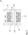
- Inductive couplers 51 and 52 may comprise plural coupling sections, for example some dedicated to the transfer of electrical power and others dedicated to the transfer of data communications as shown for example in Figs. 4 and 5 .
- the second chamber 21 can be a pressure compensated chamber the pressure of which is balanced to the surrounding ambient pressure, in particular the subsea pressure when the housing assembly 100 is installed subsea.
- the differential pressure across the walls of the second housing body 22 is accordingly relatively low.
- the housing body 22 has an opening in which the second coupling section 52 is located. This opening is sealed against the first housing body 12, for example by means of O-ring seals 29. Double seals are preferably provided.
- the second chamber 21 may be filled with a substantially incompressible medium, in particular a dielectric liquid or gel, such as oil or the like.
- a substantially incompressible medium in particular a dielectric liquid or gel, such as oil or the like.
- the electric and electronic components of the unit 56 can be adapted to operate in such environment, or, as mentioned above, unit 56 may be located outside chamber 21, for example in a subsea canister to which the sensor 200 is connected, or topside. Pressure compensation can occur by means of a dedicated pressure compensator forming part of the subsea housing assembly 100 (not shown).
- the subsea housing assembly 100 may be connected to a subsea cable in form of an oil filled hose, wherein the inner volume of such hose is filled with a dielectric liquid (in particular oil) and is pressure compensated against the ambient environment due to the flexibility of the hose.
- Pressure compensation of the second chamber 21 can occur via such hose, for example by allowing a flow communication through the opening 26 between the inner volume of the hose and the chamber 21, or by providing some pressure transmitting element in the opening, such as a membrane or bellows.
- the second chamber 21 may be a pressure resistant chamber.
- a predefined pressure below 10 bar, preferably below 5 bar or below 1.5 bar, such as close to atmospheric pressure may be maintained in chamber 21.
- another wall comprising another inductive coupler or a standard penetrator providing a pressure barrier (not shown) can be provided in the opening 26. Since such wall has to withstand the differential pressure between the interior pressure of chamber 21 and the external subsea pressure when installed subsea, the pressure difference is usually lower compared to the pressure difference that can prevail at barriers potentially exposed to the pressure of process fluid.
- the second housing portion 20 may for example comprise a fitting or connector for providing a connection to a subsea cable.
- a further unit such as a control module or the like, may be mounted directly to the subsea housing assembly 100.
- the insulation resistance would in such case be measured between the metal cage provided by the first and second housing bodies 12, 22 and the respective coupling section 51, 52, so that insulation resistance can be kept high.
- the insulation resistance can also be maintained during high pressure testing.
- a subsea housing assembly 100 that is part of an embodiment of a subsea sensor 200 is illustrated.
- the subsea housing assembly 100 is mounted to a subsea pipe 80 through which a process fluid flows.
- the first housing body 12 is pressed against the subsea pipe 80 by means of the mounting flange 16 and sealed by means of the seal 19 which may for example be a metal gasket. Note that two seals 19 may be provided to provide a double barrier.
- Sensor element 61 may for example measure the temperature and/or the pressure of the process fluid flowing through the pipe section 80, and respective readings may be modulated and transmitted by the transmitter/receiver 55 via the inductive coupler 50.
- a subsea cable in form of an oil filled hose 40 is mounted to the port opening 26 of the second housing portion 20 .
- the subsea cable may form part of the subsea sensor 200 and that a (wet mate or dry mate) connector may be provided at the other end of the subsea cable 40 for connecting the sensor 200 to another subsea device or to a topside installation.
- line 41 of subsea cable 40 is directly connected to electrical connection 25 and second coupling section 52. It will be apparent to those with skills in the art that in other embodiments further electric and electronic components such as the transmitting/receiving unit 56 can be provided.
- the opening 26 may in some embodiments allow a flow communication between the interior of subsea cable 40 and the second chamber 21, while in other embodiments separation may be provided.
- separation can be provided by a pressure transmitting element such as a membrane, or by means of a penetrator or another inductive coupler which allows maintaining a pressure difference across the opening 26.
- FIG. 3 there are shown further details of a first preferred embodiment of the present invention. Again, the explanations provided above with respect to Figs. 1 and 2 apply mutatis mutandis to the embodiment shown in Fig. 3 and only the differences and improvements are discussed in the following.
- first and second coupling sections 51, 52 are shown to be implemented as coils which are preferably arranged coaxially or concentrically.
- the first coil 51 is mounted with a small gap on one side of wall 30 and the second coil 52 is mounted with a small gap on the other side of wall 30. In other embodiments there may be no gap between the coils 51, 52 and wall 30.
- a first guide body 53 is placed on the first coil 51, or the first coil is placed inside the first guide body which is then mounted.
- the first guide body 53 preferably encloses the first coil 51 except where the first coil faces the wall 30 so as to capture as much of the magnetic field emanating from the first coil 51 as possible and direct the same through the wall 30 towards the second coil 52, thereby utilizing more of the generated field and thus increasing the efficiency inductive coupler.
- a preferred shape for the first guide body 53 is known as the pot core. More precisely, essentially half a pot core is used for the first guide 53, with the second guide body 54 essentially providing the other half. Such pot cores are well known to those with skills in the art. Sample shapes are for example shown in https://en.wikipedia.org/wiki/Magnetic_core#Pot_core.
- a second guide body 54 is placed on the second coil 52.
- the second guide body 54 preferably encloses the second coil 52 except where the second coil faces the wall 30 so as to capture as much of the magnetic field emanating from the second coil 52 as possible and direct the same through the wall 30 to the first coil 51.
- the two guide bodies 53, 54 form an overall guide body for guiding the magnetic flux or field in that the guide body at the receiving coil directs the flux or field received through the wall towards the receiving coil.
- both guide bodies Preferably essentially the same shape is used for both guide bodies and both guide bodies are preferably arranged concentrically or coaxially and symmetrical with reference to wall 30. Such symmetry makes for easier production and the most homogenous distribution of the magnetic field.
- E Another preferred shape for the guide bodies 53, 54 is known as the "E” core.
- Variants of the "E” core are known as the EFD core or the ETD core.
- Sample “E” cores are for example shown in https://en.wikipedia.org/wiki/Magnetic_core#"E"_core.
- the pot core may be preferable because it may capture the magnetic field emanating from the coils more completely.
- a pot core requires more space and it may thus be preferable to implement an "E" core depending on a given housing or wall design.
- Fig. 4 there is shown an arrangement comprising two coil systems A, B for providing electrical signals or power across the wall 30.
- the explanations provided above with respect to Figs. 1 , 2 and 3 apply mutatis mutandis to the embodiment shown in Fig. 4 and only the differences and improvements are discussed in the following.
- a first coil system A comprises a first coil 51A, a second coil 52A, a first guide body 53A, and a second guide body 54A which may be configured as described with reference to Fig. 3 .
- a second coil system B comprising first coil 51B, a second coil 52B, a first guide body 53B, and a second guide body 54B may be implemented similar to or different from the first coil system A.
- the outer dimensions of both coil systems are similar.
- the coils in both systems may be similar or different, for example by having a similar or different numbers of windings resulting in similar or different inductances.
- a single coil set may generally be sufficient to transmit data and power into and data out of the first chamber 11, for example by employing a time multiplex scheme.
- Providing a second set of coils provides a variety of additional design choices. For example distinct paths (and adapted coil sets) may be provided for transmitting power and/or control data into the first chamber and/or for transmitting sensor data out of the first chamber.
- coil set A may be adapted for transmitting power into the first chamber 11
- coil set B may be adapted for transmitting data out of the first chamber 11. In such a configuration it may be advantageous to adapt the parameters of the coil sets in accordance with what they need to transmit (power or data).
- the second coil set may be provided as a redundancy measure, noting that subsea sensors and connectors typically need to be designed for extremely long lifetimes, e.g. in excess of 20 or 30 years.
- the coil sets A and B are shown to be arranged next to each other. In other embodiments the coil sets may also be arranged around the same cores, as for example shown in Fig. 5 , where the coils of the coil sets share the guide bodies.
- the first coils 51A, 51B of the coil sets A and B are mounted inside the first guide body 53 and the second coils 52A, 52B of the coil sets A and B are mounted inside the second guide body 54.
- the coils may be similar or different, for example by having a similar or different numbers of windings resulting in similar or different inductances.
- the advantage of the arrangement shown in Fig. 5 is that the available space can by utilized for large guide bodies whereas in the arrangement shown in Fig. 4 the guide bodies need to share the available space.
- the parameters of the coil sets may be adapted to the coil's purpose.
- the first coil set A may be dedicated to the energy transmission and may be adapted to have a bigger inductance so as to allow better transmissions at low frequencies.
- Fig. 6 there is shown an arrangement suitable for thinner walls comprising planar coils 51, 52 manufactured in a most cost effective manner using PCB manufacturing processes.
- the guide bodies 53, 54 are flat and placed on the PCB coils. With this method multiple coils (i.e. multiple channels) may be realized on one PCB substrate at very low extra cost.
- the transmission may preferably be effected using higher frequencies, for example frequencies above 10kHz or even above 100kHz, in some configurations even above 1MHz.
- the guide bodies may be wrapped around the edges of the PCB (not shown).
- planar guide bodies may in embodiments be shaped so as to enhance the guiding of the magnetic field, for example by providing a planar "E" core.
- Sample shapes are for example shown in https://en.wikipedia.org/wiki/Magnetic_core#Planar_core.
- planar (or flat) coils may also be employed which generally provide higher inductances but maintain the low planar profile where the height of the inductive coupler structure is limited.
- the subsea housing assembly 100 is described above primarily with respect to the use in a subsea sensor 200 which may be attached to a pipe section exposed to process fluid pressures of 1000 bar or more, yet it is to be understood that it may also be used in other applications, in particular where the integrity of a pressure barrier is of importance but where the operating pressures are lower, for example in other subsea equipment such as connectors or canisters exposed to seawater pressures of approximately 100 bar at 1000 m water depth or approximately 300 bar at 3000 m water depth.
- Electrical penetrators are a key design concern, particularly for connectors, and with the present invention it may be possible to replace at least some of the electrical penetrators by an inductive penetrator enclosed in a subsea housing in accordance with the present invention.
- Other applications may include the application in a subsea control unit where the integrity of a one atmospheric chamber needs to be ensured. Other applications are equally conceivable.
Landscapes
- Engineering & Computer Science (AREA)
- Computer Networks & Wireless Communication (AREA)
- Signal Processing (AREA)
- Microelectronics & Electronic Packaging (AREA)
- Measuring Fluid Pressure (AREA)
Priority Applications (1)
| Application Number | Priority Date | Filing Date | Title |
|---|---|---|---|
| EP18151854.9A EP3511517B1 (fr) | 2018-01-16 | 2018-01-16 | Ensemble de logement sous-marin |
Applications Claiming Priority (1)
| Application Number | Priority Date | Filing Date | Title |
|---|---|---|---|
| EP18151854.9A EP3511517B1 (fr) | 2018-01-16 | 2018-01-16 | Ensemble de logement sous-marin |
Publications (2)
| Publication Number | Publication Date |
|---|---|
| EP3511517A1 true EP3511517A1 (fr) | 2019-07-17 |
| EP3511517B1 EP3511517B1 (fr) | 2020-05-27 |
Family
ID=60997362
Family Applications (1)
| Application Number | Title | Priority Date | Filing Date |
|---|---|---|---|
| EP18151854.9A Active EP3511517B1 (fr) | 2018-01-16 | 2018-01-16 | Ensemble de logement sous-marin |
Country Status (1)
| Country | Link |
|---|---|
| EP (1) | EP3511517B1 (fr) |
Cited By (3)
| Publication number | Priority date | Publication date | Assignee | Title |
|---|---|---|---|---|
| WO2021116323A1 (fr) | 2019-12-12 | 2021-06-17 | Siemens Aktiengesellschaft | Connecteur sous-marin |
| US11066889B2 (en) | 2018-03-13 | 2021-07-20 | Siemens Energy AS | Subsea assembly |
| WO2021239773A2 (fr) | 2020-05-26 | 2021-12-02 | Siemens Energy AS | Couplage électrique |
Families Citing this family (1)
| Publication number | Priority date | Publication date | Assignee | Title |
|---|---|---|---|---|
| GB2629986A (en) * | 2022-03-30 | 2024-11-13 | Halliburton Energy Services Inc | Sensor assembly for wireless transfer of data and power in a wellbore |
Citations (5)
| Publication number | Priority date | Publication date | Assignee | Title |
|---|---|---|---|---|
| US5455573A (en) * | 1994-04-22 | 1995-10-03 | Panex Corporation | Inductive coupler for well tools |
| WO2014123425A1 (fr) * | 2013-02-06 | 2014-08-14 | Aker Subsea As | Vanne sous-marine |
| WO2015139953A1 (fr) * | 2014-03-19 | 2015-09-24 | Siemens Aktiengesellschaft | Dispositif de commutation de puissance |
| WO2017023812A1 (fr) * | 2015-07-31 | 2017-02-09 | Cameron International Corporation | Système et procédé permettant la transmission sans contact d'énergie et de données |
| EP3269921A1 (fr) | 2016-07-14 | 2018-01-17 | Siemens Aktiengesellschaft | Ensemble de logement sous-marin |
-
2018
- 2018-01-16 EP EP18151854.9A patent/EP3511517B1/fr active Active
Patent Citations (5)
| Publication number | Priority date | Publication date | Assignee | Title |
|---|---|---|---|---|
| US5455573A (en) * | 1994-04-22 | 1995-10-03 | Panex Corporation | Inductive coupler for well tools |
| WO2014123425A1 (fr) * | 2013-02-06 | 2014-08-14 | Aker Subsea As | Vanne sous-marine |
| WO2015139953A1 (fr) * | 2014-03-19 | 2015-09-24 | Siemens Aktiengesellschaft | Dispositif de commutation de puissance |
| WO2017023812A1 (fr) * | 2015-07-31 | 2017-02-09 | Cameron International Corporation | Système et procédé permettant la transmission sans contact d'énergie et de données |
| EP3269921A1 (fr) | 2016-07-14 | 2018-01-17 | Siemens Aktiengesellschaft | Ensemble de logement sous-marin |
Cited By (5)
| Publication number | Priority date | Publication date | Assignee | Title |
|---|---|---|---|---|
| US11066889B2 (en) | 2018-03-13 | 2021-07-20 | Siemens Energy AS | Subsea assembly |
| WO2021116323A1 (fr) | 2019-12-12 | 2021-06-17 | Siemens Aktiengesellschaft | Connecteur sous-marin |
| CN114829738A (zh) * | 2019-12-12 | 2022-07-29 | 西门子能源环球有限责任两合公司 | 海底连接器 |
| US12248033B2 (en) | 2019-12-12 | 2025-03-11 | Siemens Energy Global GmbH & Co. KG | Subsea connector |
| WO2021239773A2 (fr) | 2020-05-26 | 2021-12-02 | Siemens Energy AS | Couplage électrique |
Also Published As
| Publication number | Publication date |
|---|---|
| EP3511517B1 (fr) | 2020-05-27 |
Similar Documents
| Publication | Publication Date | Title |
|---|---|---|
| US11656106B2 (en) | Subsea housing assembly | |
| EP3511517B1 (fr) | Ensemble de logement sous-marin | |
| EP3511519B1 (fr) | Ensemble de logement sous-marin | |
| US9217327B2 (en) | Transmission system for communication between downhole elements | |
| EP3740647B1 (fr) | Ensemble de logement sous-marin | |
| EP1451445B1 (fr) | Dispositif et procede de couplage electrique | |
| US20060022786A1 (en) | Armored flat cable signalling and instrument power acquisition | |
| US11746604B2 (en) | Subsea housing assembly and subsea sensor | |
| US7847671B1 (en) | Subsea data and power transmission inductive coupler and subsea cone penetrating tool | |
| US11686162B2 (en) | Wireless electrical feedthrough wetmate connector | |
| WO2018185338A1 (fr) | Système capteur | |
| BR112020013499B1 (pt) | Montagem de alojamento submarino e sensor submarino | |
| EP3701228A1 (fr) | Système capteur |
Legal Events
| Date | Code | Title | Description |
|---|---|---|---|
| PUAI | Public reference made under article 153(3) epc to a published international application that has entered the european phase |
Free format text: ORIGINAL CODE: 0009012 |
|
| STAA | Information on the status of an ep patent application or granted ep patent |
Free format text: STATUS: THE APPLICATION HAS BEEN PUBLISHED |
|
| AK | Designated contracting states |
Kind code of ref document: A1 Designated state(s): AL AT BE BG CH CY CZ DE DK EE ES FI FR GB GR HR HU IE IS IT LI LT LU LV MC MK MT NL NO PL PT RO RS SE SI SK SM TR |
|
| AX | Request for extension of the european patent |
Extension state: BA ME |
|
| STAA | Information on the status of an ep patent application or granted ep patent |
Free format text: STATUS: REQUEST FOR EXAMINATION WAS MADE |
|
| RIN1 | Information on inventor provided before grant (corrected) |
Inventor name: LUDWIG, KLAUS Inventor name: GOETZ, JUERGEN |
|
| 17P | Request for examination filed |
Effective date: 20190819 |
|
| RBV | Designated contracting states (corrected) |
Designated state(s): AL AT BE BG CH CY CZ DE DK EE ES FI FR GB GR HR HU IE IS IT LI LT LU LV MC MK MT NL NO PL PT RO RS SE SI SK SM TR |
|
| RIN1 | Information on inventor provided before grant (corrected) |
Inventor name: LUDWIG, KLAUS Inventor name: GOETZ, JUERGEN |
|
| RIC1 | Information provided on ipc code assigned before grant |
Ipc: E21B 33/038 20060101AFI20191202BHEP Ipc: H04B 5/00 20060101ALI20191202BHEP |
|
| GRAP | Despatch of communication of intention to grant a patent |
Free format text: ORIGINAL CODE: EPIDOSNIGR1 |
|
| STAA | Information on the status of an ep patent application or granted ep patent |
Free format text: STATUS: GRANT OF PATENT IS INTENDED |
|
| INTG | Intention to grant announced |
Effective date: 20200114 |
|
| GRAS | Grant fee paid |
Free format text: ORIGINAL CODE: EPIDOSNIGR3 |
|
| GRAA | (expected) grant |
Free format text: ORIGINAL CODE: 0009210 |
|
| STAA | Information on the status of an ep patent application or granted ep patent |
Free format text: STATUS: THE PATENT HAS BEEN GRANTED |
|
| AK | Designated contracting states |
Kind code of ref document: B1 Designated state(s): AL AT BE BG CH CY CZ DE DK EE ES FI FR GB GR HR HU IE IS IT LI LT LU LV MC MK MT NL NO PL PT RO RS SE SI SK SM TR |
|
| REG | Reference to a national code |
Ref country code: GB Ref legal event code: FG4D |
|
| REG | Reference to a national code |
Ref country code: CH Ref legal event code: EP |
|
| REG | Reference to a national code |
Ref country code: AT Ref legal event code: REF Ref document number: 1274733 Country of ref document: AT Kind code of ref document: T Effective date: 20200615 |
|
| REG | Reference to a national code |
Ref country code: DE Ref legal event code: R096 Ref document number: 602018004790 Country of ref document: DE |
|
| REG | Reference to a national code |
Ref country code: NO Ref legal event code: T2 Effective date: 20200527 Ref country code: LT Ref legal event code: MG4D |
|
| PG25 | Lapsed in a contracting state [announced via postgrant information from national office to epo] |
Ref country code: FI Free format text: LAPSE BECAUSE OF FAILURE TO SUBMIT A TRANSLATION OF THE DESCRIPTION OR TO PAY THE FEE WITHIN THE PRESCRIBED TIME-LIMIT Effective date: 20200527 Ref country code: SE Free format text: LAPSE BECAUSE OF FAILURE TO SUBMIT A TRANSLATION OF THE DESCRIPTION OR TO PAY THE FEE WITHIN THE PRESCRIBED TIME-LIMIT Effective date: 20200527 Ref country code: LT Free format text: LAPSE BECAUSE OF FAILURE TO SUBMIT A TRANSLATION OF THE DESCRIPTION OR TO PAY THE FEE WITHIN THE PRESCRIBED TIME-LIMIT Effective date: 20200527 Ref country code: GR Free format text: LAPSE BECAUSE OF FAILURE TO SUBMIT A TRANSLATION OF THE DESCRIPTION OR TO PAY THE FEE WITHIN THE PRESCRIBED TIME-LIMIT Effective date: 20200828 Ref country code: IS Free format text: LAPSE BECAUSE OF FAILURE TO SUBMIT A TRANSLATION OF THE DESCRIPTION OR TO PAY THE FEE WITHIN THE PRESCRIBED TIME-LIMIT Effective date: 20200927 Ref country code: PT Free format text: LAPSE BECAUSE OF FAILURE TO SUBMIT A TRANSLATION OF THE DESCRIPTION OR TO PAY THE FEE WITHIN THE PRESCRIBED TIME-LIMIT Effective date: 20200928 |
|
| REG | Reference to a national code |
Ref country code: NL Ref legal event code: MP Effective date: 20200527 |
|
| PG25 | Lapsed in a contracting state [announced via postgrant information from national office to epo] |
Ref country code: RS Free format text: LAPSE BECAUSE OF FAILURE TO SUBMIT A TRANSLATION OF THE DESCRIPTION OR TO PAY THE FEE WITHIN THE PRESCRIBED TIME-LIMIT Effective date: 20200527 Ref country code: LV Free format text: LAPSE BECAUSE OF FAILURE TO SUBMIT A TRANSLATION OF THE DESCRIPTION OR TO PAY THE FEE WITHIN THE PRESCRIBED TIME-LIMIT Effective date: 20200527 Ref country code: HR Free format text: LAPSE BECAUSE OF FAILURE TO SUBMIT A TRANSLATION OF THE DESCRIPTION OR TO PAY THE FEE WITHIN THE PRESCRIBED TIME-LIMIT Effective date: 20200527 Ref country code: BG Free format text: LAPSE BECAUSE OF FAILURE TO SUBMIT A TRANSLATION OF THE DESCRIPTION OR TO PAY THE FEE WITHIN THE PRESCRIBED TIME-LIMIT Effective date: 20200827 |
|
| REG | Reference to a national code |
Ref country code: AT Ref legal event code: MK05 Ref document number: 1274733 Country of ref document: AT Kind code of ref document: T Effective date: 20200527 |
|
| PG25 | Lapsed in a contracting state [announced via postgrant information from national office to epo] |
Ref country code: NL Free format text: LAPSE BECAUSE OF FAILURE TO SUBMIT A TRANSLATION OF THE DESCRIPTION OR TO PAY THE FEE WITHIN THE PRESCRIBED TIME-LIMIT Effective date: 20200527 Ref country code: AL Free format text: LAPSE BECAUSE OF FAILURE TO SUBMIT A TRANSLATION OF THE DESCRIPTION OR TO PAY THE FEE WITHIN THE PRESCRIBED TIME-LIMIT Effective date: 20200527 |
|
| PG25 | Lapsed in a contracting state [announced via postgrant information from national office to epo] |
Ref country code: ES Free format text: LAPSE BECAUSE OF FAILURE TO SUBMIT A TRANSLATION OF THE DESCRIPTION OR TO PAY THE FEE WITHIN THE PRESCRIBED TIME-LIMIT Effective date: 20200527 Ref country code: CZ Free format text: LAPSE BECAUSE OF FAILURE TO SUBMIT A TRANSLATION OF THE DESCRIPTION OR TO PAY THE FEE WITHIN THE PRESCRIBED TIME-LIMIT Effective date: 20200527 Ref country code: AT Free format text: LAPSE BECAUSE OF FAILURE TO SUBMIT A TRANSLATION OF THE DESCRIPTION OR TO PAY THE FEE WITHIN THE PRESCRIBED TIME-LIMIT Effective date: 20200527 Ref country code: DK Free format text: LAPSE BECAUSE OF FAILURE TO SUBMIT A TRANSLATION OF THE DESCRIPTION OR TO PAY THE FEE WITHIN THE PRESCRIBED TIME-LIMIT Effective date: 20200527 Ref country code: SM Free format text: LAPSE BECAUSE OF FAILURE TO SUBMIT A TRANSLATION OF THE DESCRIPTION OR TO PAY THE FEE WITHIN THE PRESCRIBED TIME-LIMIT Effective date: 20200527 Ref country code: EE Free format text: LAPSE BECAUSE OF FAILURE TO SUBMIT A TRANSLATION OF THE DESCRIPTION OR TO PAY THE FEE WITHIN THE PRESCRIBED TIME-LIMIT Effective date: 20200527 Ref country code: IT Free format text: LAPSE BECAUSE OF FAILURE TO SUBMIT A TRANSLATION OF THE DESCRIPTION OR TO PAY THE FEE WITHIN THE PRESCRIBED TIME-LIMIT Effective date: 20200527 Ref country code: RO Free format text: LAPSE BECAUSE OF FAILURE TO SUBMIT A TRANSLATION OF THE DESCRIPTION OR TO PAY THE FEE WITHIN THE PRESCRIBED TIME-LIMIT Effective date: 20200527 |
|
| RAP2 | Party data changed (patent owner data changed or rights of a patent transferred) |
Owner name: SIEMENS ENERGY AS |
|
| PG25 | Lapsed in a contracting state [announced via postgrant information from national office to epo] |
Ref country code: PL Free format text: LAPSE BECAUSE OF FAILURE TO SUBMIT A TRANSLATION OF THE DESCRIPTION OR TO PAY THE FEE WITHIN THE PRESCRIBED TIME-LIMIT Effective date: 20200527 Ref country code: SK Free format text: LAPSE BECAUSE OF FAILURE TO SUBMIT A TRANSLATION OF THE DESCRIPTION OR TO PAY THE FEE WITHIN THE PRESCRIBED TIME-LIMIT Effective date: 20200527 |
|
| REG | Reference to a national code |
Ref country code: DE Ref legal event code: R097 Ref document number: 602018004790 Country of ref document: DE |
|
| REG | Reference to a national code |
Ref country code: NO Ref legal event code: CREP Representative=s name: ONSAGERS AS, POSTBOKS 1813, VIKA, 0123 OSLO, NORGE Ref country code: NO Ref legal event code: CHAD Owner name: SIEMENS ENERGY AS, NO |
|
| PLBE | No opposition filed within time limit |
Free format text: ORIGINAL CODE: 0009261 |
|
| STAA | Information on the status of an ep patent application or granted ep patent |
Free format text: STATUS: NO OPPOSITION FILED WITHIN TIME LIMIT |
|
| REG | Reference to a national code |
Ref country code: CH Ref legal event code: NV Representative=s name: SIEMENS SCHWEIZ AG, CH |
|
| 26N | No opposition filed |
Effective date: 20210302 |
|
| PG25 | Lapsed in a contracting state [announced via postgrant information from national office to epo] |
Ref country code: SI Free format text: LAPSE BECAUSE OF FAILURE TO SUBMIT A TRANSLATION OF THE DESCRIPTION OR TO PAY THE FEE WITHIN THE PRESCRIBED TIME-LIMIT Effective date: 20200527 |
|
| REG | Reference to a national code |
Ref country code: GB Ref legal event code: 732E Free format text: REGISTERED BETWEEN 20210520 AND 20210526 |
|
| REG | Reference to a national code |
Ref country code: DE Ref legal event code: R119 Ref document number: 602018004790 Country of ref document: DE |
|
| PG25 | Lapsed in a contracting state [announced via postgrant information from national office to epo] |
Ref country code: MC Free format text: LAPSE BECAUSE OF FAILURE TO SUBMIT A TRANSLATION OF THE DESCRIPTION OR TO PAY THE FEE WITHIN THE PRESCRIBED TIME-LIMIT Effective date: 20200527 |
|
| REG | Reference to a national code |
Ref country code: CH Ref legal event code: PL |
|
| PG25 | Lapsed in a contracting state [announced via postgrant information from national office to epo] |
Ref country code: LU Free format text: LAPSE BECAUSE OF NON-PAYMENT OF DUE FEES Effective date: 20210116 |
|
| REG | Reference to a national code |
Ref country code: BE Ref legal event code: MM Effective date: 20210131 |
|
| PG25 | Lapsed in a contracting state [announced via postgrant information from national office to epo] |
Ref country code: FR Free format text: LAPSE BECAUSE OF NON-PAYMENT OF DUE FEES Effective date: 20210131 |
|
| PG25 | Lapsed in a contracting state [announced via postgrant information from national office to epo] |
Ref country code: LI Free format text: LAPSE BECAUSE OF NON-PAYMENT OF DUE FEES Effective date: 20210131 Ref country code: DE Free format text: LAPSE BECAUSE OF NON-PAYMENT OF DUE FEES Effective date: 20210803 Ref country code: CH Free format text: LAPSE BECAUSE OF NON-PAYMENT OF DUE FEES Effective date: 20210131 |
|
| PG25 | Lapsed in a contracting state [announced via postgrant information from national office to epo] |
Ref country code: IE Free format text: LAPSE BECAUSE OF NON-PAYMENT OF DUE FEES Effective date: 20210116 |
|
| PG25 | Lapsed in a contracting state [announced via postgrant information from national office to epo] |
Ref country code: BE Free format text: LAPSE BECAUSE OF NON-PAYMENT OF DUE FEES Effective date: 20210131 |
|
| PG25 | Lapsed in a contracting state [announced via postgrant information from national office to epo] |
Ref country code: CY Free format text: LAPSE BECAUSE OF FAILURE TO SUBMIT A TRANSLATION OF THE DESCRIPTION OR TO PAY THE FEE WITHIN THE PRESCRIBED TIME-LIMIT Effective date: 20200527 |
|
| PG25 | Lapsed in a contracting state [announced via postgrant information from national office to epo] |
Ref country code: HU Free format text: LAPSE BECAUSE OF FAILURE TO SUBMIT A TRANSLATION OF THE DESCRIPTION OR TO PAY THE FEE WITHIN THE PRESCRIBED TIME-LIMIT; INVALID AB INITIO Effective date: 20180116 |
|
| PG25 | Lapsed in a contracting state [announced via postgrant information from national office to epo] |
Ref country code: MK Free format text: LAPSE BECAUSE OF FAILURE TO SUBMIT A TRANSLATION OF THE DESCRIPTION OR TO PAY THE FEE WITHIN THE PRESCRIBED TIME-LIMIT Effective date: 20200527 |
|
| PG25 | Lapsed in a contracting state [announced via postgrant information from national office to epo] |
Ref country code: TR Free format text: LAPSE BECAUSE OF FAILURE TO SUBMIT A TRANSLATION OF THE DESCRIPTION OR TO PAY THE FEE WITHIN THE PRESCRIBED TIME-LIMIT Effective date: 20200527 |
|
| PG25 | Lapsed in a contracting state [announced via postgrant information from national office to epo] |
Ref country code: MT Free format text: LAPSE BECAUSE OF FAILURE TO SUBMIT A TRANSLATION OF THE DESCRIPTION OR TO PAY THE FEE WITHIN THE PRESCRIBED TIME-LIMIT Effective date: 20200527 |
|
| PGFP | Annual fee paid to national office [announced via postgrant information from national office to epo] |
Ref country code: GB Payment date: 20260126 Year of fee payment: 9 |
|
| PGFP | Annual fee paid to national office [announced via postgrant information from national office to epo] |
Ref country code: NO Payment date: 20260120 Year of fee payment: 9 |