EP3512029B1 - Flexible sekundärbatterie - Google Patents
Flexible sekundärbatterie Download PDFInfo
- Publication number
- EP3512029B1 EP3512029B1 EP17877575.5A EP17877575A EP3512029B1 EP 3512029 B1 EP3512029 B1 EP 3512029B1 EP 17877575 A EP17877575 A EP 17877575A EP 3512029 B1 EP3512029 B1 EP 3512029B1
- Authority
- EP
- European Patent Office
- Prior art keywords
- electrode
- coating layer
- secondary battery
- active material
- flexible secondary
- Prior art date
- Legal status (The legal status is an assumption and is not a legal conclusion. Google has not performed a legal analysis and makes no representation as to the accuracy of the status listed.)
- Active
Links
Images


Classifications
-
- H—ELECTRICITY
- H01—ELECTRIC ELEMENTS
- H01M—PROCESSES OR MEANS, e.g. BATTERIES, FOR THE DIRECT CONVERSION OF CHEMICAL ENERGY INTO ELECTRICAL ENERGY
- H01M4/00—Electrodes
- H01M4/02—Electrodes composed of, or comprising, active material
- H01M4/36—Selection of substances as active materials, active masses, active liquids
- H01M4/362—Composites
- H01M4/366—Composites as layered products
-
- H—ELECTRICITY
- H01—ELECTRIC ELEMENTS
- H01M—PROCESSES OR MEANS, e.g. BATTERIES, FOR THE DIRECT CONVERSION OF CHEMICAL ENERGY INTO ELECTRICAL ENERGY
- H01M4/00—Electrodes
- H01M4/02—Electrodes composed of, or comprising, active material
- H01M4/64—Carriers or collectors
- H01M4/70—Carriers or collectors characterised by shape or form
- H01M4/78—Shapes other than plane or cylindrical, e.g. helical
-
- H—ELECTRICITY
- H01—ELECTRIC ELEMENTS
- H01M—PROCESSES OR MEANS, e.g. BATTERIES, FOR THE DIRECT CONVERSION OF CHEMICAL ENERGY INTO ELECTRICAL ENERGY
- H01M10/00—Secondary cells; Manufacture thereof
- H01M10/05—Accumulators with non-aqueous electrolyte
- H01M10/058—Construction or manufacture
-
- H—ELECTRICITY
- H01—ELECTRIC ELEMENTS
- H01M—PROCESSES OR MEANS, e.g. BATTERIES, FOR THE DIRECT CONVERSION OF CHEMICAL ENERGY INTO ELECTRICAL ENERGY
- H01M10/00—Secondary cells; Manufacture thereof
- H01M10/05—Accumulators with non-aqueous electrolyte
- H01M10/058—Construction or manufacture
- H01M10/0587—Construction or manufacture of accumulators having only wound construction elements, i.e. wound positive electrodes, wound negative electrodes and wound separators
-
- H—ELECTRICITY
- H01—ELECTRIC ELEMENTS
- H01M—PROCESSES OR MEANS, e.g. BATTERIES, FOR THE DIRECT CONVERSION OF CHEMICAL ENERGY INTO ELECTRICAL ENERGY
- H01M10/00—Secondary cells; Manufacture thereof
- H01M10/42—Methods or arrangements for servicing or maintenance of secondary cells or secondary half-cells
- H01M10/4235—Safety or regulating additives or arrangements in electrodes, separators or electrolyte
-
- H—ELECTRICITY
- H01—ELECTRIC ELEMENTS
- H01M—PROCESSES OR MEANS, e.g. BATTERIES, FOR THE DIRECT CONVERSION OF CHEMICAL ENERGY INTO ELECTRICAL ENERGY
- H01M4/00—Electrodes
- H01M4/02—Electrodes composed of, or comprising, active material
- H01M4/36—Selection of substances as active materials, active masses, active liquids
-
- H—ELECTRICITY
- H01—ELECTRIC ELEMENTS
- H01M—PROCESSES OR MEANS, e.g. BATTERIES, FOR THE DIRECT CONVERSION OF CHEMICAL ENERGY INTO ELECTRICAL ENERGY
- H01M4/00—Electrodes
- H01M4/02—Electrodes composed of, or comprising, active material
- H01M4/62—Selection of inactive substances as ingredients for active masses, e.g. binders, fillers
- H01M4/628—Inhibitors, e.g. gassing inhibitors, corrosion inhibitors
-
- H—ELECTRICITY
- H01—ELECTRIC ELEMENTS
- H01M—PROCESSES OR MEANS, e.g. BATTERIES, FOR THE DIRECT CONVERSION OF CHEMICAL ENERGY INTO ELECTRICAL ENERGY
- H01M4/00—Electrodes
- H01M4/02—Electrodes composed of, or comprising, active material
- H01M4/64—Carriers or collectors
- H01M4/66—Selection of materials
- H01M4/661—Metal or alloys, e.g. alloy coatings
-
- H—ELECTRICITY
- H01—ELECTRIC ELEMENTS
- H01M—PROCESSES OR MEANS, e.g. BATTERIES, FOR THE DIRECT CONVERSION OF CHEMICAL ENERGY INTO ELECTRICAL ENERGY
- H01M4/00—Electrodes
- H01M4/02—Electrodes composed of, or comprising, active material
- H01M2004/025—Electrodes composed of, or comprising, active material with shapes other than plane or cylindrical
-
- H—ELECTRICITY
- H01—ELECTRIC ELEMENTS
- H01M—PROCESSES OR MEANS, e.g. BATTERIES, FOR THE DIRECT CONVERSION OF CHEMICAL ENERGY INTO ELECTRICAL ENERGY
- H01M4/00—Electrodes
- H01M4/02—Electrodes composed of, or comprising, active material
-
- H—ELECTRICITY
- H01—ELECTRIC ELEMENTS
- H01M—PROCESSES OR MEANS, e.g. BATTERIES, FOR THE DIRECT CONVERSION OF CHEMICAL ENERGY INTO ELECTRICAL ENERGY
- H01M4/00—Electrodes
- H01M4/02—Electrodes composed of, or comprising, active material
- H01M4/13—Electrodes for accumulators with non-aqueous electrolyte, e.g. for lithium-accumulators; Processes of manufacture thereof
-
- Y—GENERAL TAGGING OF NEW TECHNOLOGICAL DEVELOPMENTS; GENERAL TAGGING OF CROSS-SECTIONAL TECHNOLOGIES SPANNING OVER SEVERAL SECTIONS OF THE IPC; TECHNICAL SUBJECTS COVERED BY FORMER USPC CROSS-REFERENCE ART COLLECTIONS [XRACs] AND DIGESTS
- Y02—TECHNOLOGIES OR APPLICATIONS FOR MITIGATION OR ADAPTATION AGAINST CLIMATE CHANGE
- Y02E—REDUCTION OF GREENHOUSE GAS [GHG] EMISSIONS, RELATED TO ENERGY GENERATION, TRANSMISSION OR DISTRIBUTION
- Y02E60/00—Enabling technologies; Technologies with a potential or indirect contribution to GHG emissions mitigation
- Y02E60/10—Energy storage using batteries
-
- Y—GENERAL TAGGING OF NEW TECHNOLOGICAL DEVELOPMENTS; GENERAL TAGGING OF CROSS-SECTIONAL TECHNOLOGIES SPANNING OVER SEVERAL SECTIONS OF THE IPC; TECHNICAL SUBJECTS COVERED BY FORMER USPC CROSS-REFERENCE ART COLLECTIONS [XRACs] AND DIGESTS
- Y02—TECHNOLOGIES OR APPLICATIONS FOR MITIGATION OR ADAPTATION AGAINST CLIMATE CHANGE
- Y02P—CLIMATE CHANGE MITIGATION TECHNOLOGIES IN THE PRODUCTION OR PROCESSING OF GOODS
- Y02P70/00—Climate change mitigation technologies in the production process for final industrial or consumer products
- Y02P70/50—Manufacturing or production processes characterised by the final manufactured product
Definitions
- the present disclosure relates to a flexible secondary battery. More particularly, the present disclosure relates to a flexible secondary battery which is freely deformable and has improved flexibility.
- secondary batteries have been increasingly in use in various industrial fields.
- secondary batteries have been diversified in terms of output, capacity and structure.
- a secondary battery in general, includes an electrode assembly obtained by applying an active material to the surface of a plate-like current collector to form a cathode and an anode and interposing a separator between the cathode and the anode.
- the electrode assembly is received generally in a cylindrical or prismatic metallic can or a pouch type casing including an aluminum sheet together with a liquid electrolyte or solid electrolyte.
- the electrode assembly may have a jelly-roll shape in which sheet-type cathodes/separators/anodes are wound, or a structure in which a plurality of unit electrodes having a thin plate shape are stacked successively. Therefore, the structure of an electrode (cathode and anode) in the electrode assembly essentially has a plate-like shape.
- Such a plate-like electrode structure is advantageous in that it can realize a high degree of integration upon winding or stacking of an electrode assembly.
- it has a limitation in structural deformation depending on needs in industrial fields.
- such a plate-like electrode structure has some problems, since it is sensitive to a change in volume of an electrode during charging/discharging, does not allow easy emission of gases generated in a cell toward the outside, and may cause a large difference in potential from one electrode to another electrode.
- a cylindrical battery, coin battery or prismatic battery has a specific shape, it is not freely deformable, has a limitation in use, and is not amenable to free deformation, such as distortion or bending, in response to the purpose of use a battery.
- WO 2018/111016 A1 relates to a cable-type secondary battery comprising: a cable-type core part; a cathode wire and an anode wire wound around the outer surface of the cable-type core part.
- KR 10-2016-0055755 is concerned with a battery comprising an electrode assembly comprising a first electrode including one or two fibrous first structure; and a second electrode including one or two fibrous second structure spirally surrounding the first structure.
- KR 10-2007-0009231 provides a thread-type battery prepared by the steps of: forming thread-type positive electrode and negative electrode into thread and subjecting the prepared thread to protective coating.
- the present disclosure is designed to solve the problems of the related art, and therefore the present disclosure is directed to providing a flexible secondary battery which is easily deformable and has an improved structure so as to maintain the stability and high performance of a second battery.
- the flexible batteries according to the following embodiments.
- a flexible secondary battery which includes:
- each of the first electrode current collector and the second electrode current collector independently includes: stainless steel; aluminum; nickel; titanium; baked carbon; copper; stainless steel surface-treated with carbon, nickel, titanium or silver; aluminum-cadmium alloy; non-conductive polymer surface-treated with a conductive material; conductive polymer; metal paste containing metal powder of Ni, Al, Au, Ag, Al, Pd/Ag, Cr, Ta, Cu, Ba or ITO; or carbon paste containing carbon powder of graphite, carbon black or carbon nanotube.
- the flexible secondary battery of the first or the second embodiment wherein the first electrode is a cathode or anode and the second electrode is an anode or cathode corresponding to the first electrode.
- the flexible secondary battery of any one of the first to the third embodiments wherein when the first electrode is an anode and the second electrode is a cathode, the first electrode active material includes any one active material particle selected from the group consisting of natural graphite, artificial graphite or carbonaceous materials; metals (Me) of lithium-containing titanium composite oxide (LTO), Si, Sn, Li, Zn, Mg, Cd, Ce, Ni or Fe; alloys including the metal (Me); oxides (MeOx) of the metals (Me); and composites of the metals (Me) with carbon, or a combination of two or more of them, and the second electrode active material includes any one active material particle selected from the group consisting of LiCoO 2 , LiNiO 2 , LiMn 2 O 4 , LiCoPO 4 , LiFePO 4 , LiNiMnCoO 2 and LiNi 1-x-y-z Co x M1 y M2
- the first electrode active material of the flexible secondary battery of any one of the first to the fourth embodiments may include any one active material particle selected from the group consisting of LiCoO 2 , LiNiO 2 , LiMn 2 O 4 , LiCoPO 4 , LiFePO 4 , LiNiMnCoO 2 and LiNi 1-x-y-z Co x M1 y M2 z O 2 (wherein each of M1 and M2 independently represents any one selected from the group consisting of Al, Ni, Co, Fe, Mn, V, Cr, Ti, W, Ta, Mg and Mo, each of x, y and z independently represents the atomic fraction of an element forming the oxide and 0 ⁇ x ⁇ 0.5, 0 ⁇ y ⁇ 0.5, 0 ⁇ z ⁇ 0.5 and 0 ⁇ x + y + z ⁇ 1), or a combination of two or more of them, or a combination of two or more of them,
- each of the first insulation coating layer and the second insulation coating layer independently includes a porous polymer coating layer; an inorganic solid-state electrolyte coating layer; an organic solid-state coating layer; or a polyolefin foam separator.
- the flexible secondary battery of any one of the first to the fifth embodiments wherein the third insulation coating layer includes a porous polymer coating layer; an inorganic solid-state electrolyte coating layer; an organic solid-state coating layer; or a polyolefin foam separator.
- the flexible secondary battery according to the present disclosure includes the first electrode and the second electrode, which have a longitudinally extended shape and are disposed alternately in contact with each other, and thus can improve the flexibility of the battery. Therefore, it is possible to reduce the risk of a short-circuit caused by deformation, unlike a foil type electrode which may form a sharp portion by deformation to cause a short-circuit.
- the force applied to the electrode active material layers may be dispersed, thereby contributing to prevention of the separation of an active material layer from a current collector.
- the flexible secondary battery according to the present disclosure includes: a first electrode including a first electrode current collector extended longitudinally, a first electrode active material layer formed on an outside of the first electrode current collector, and a first insulation coating layer formed on an outside of the first electrode active material layer; and a second electrode including a second electrode current collector extended longitudinally, a second electrode active material layer formed on an outside of the second electrode current collector, and a second insulation coating layer formed on an outside of the second electrode active material layer, wherein the first electrode and the second electrode are helically wound in contact with each other such that they are disposed alternately in parallel with each other on the same circumference.
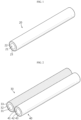
- each of the electrodes (the first electrode and the second electrode) in the flexible secondary battery according to the present disclosure is provided with an electrode current collector 21 extended longitudinally, an electrode active material layer 22 formed on the outside of the electrode current collector 21, and an insulation coating layer 23 formed on the outside of the first electrode active material layer 22.
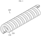
- a first electrode 30 including a first electrode current collector 31 extended longitudinally, a first electrode active material layer 32 formed on the outside of the first electrode current collector 31, and a first insulation coating layer 33 formed on the outside of the first electrode active material layer 32; and a second electrode 40 including a second electrode current collector 41 extended longitudinally, a second electrode active material layer 42 formed on the outside of the second electrode current collector 41, and a second insulation coating layer 43 formed on the outside of the second electrode active material layer 42 are prepared, and then the first electrode 30, 110 and the second electrode 40, 120 are wound so that they are disposed alternately in contact with each other. In this manner, it is possible to form the flexible secondary battery 100 according to the present disclosure.
- the first electrode and the second electrode are extended longitudinally, and have a structure in which they are wound spirally so that they are disposed alternately in contact with each other.
- 'spiral' may be interchanged with 'helix', means a shape which winds diagonally in a certain range, and generally refers to a shape similar to the shape of a general spring.
- the flexible secondary battery does not have a concentric circular shape in which one of the first electrode and the second electrode is disposed at the inside and the other is disposed at the outside so that one electrode is surrounded with the other electrode present at the outside, but has a shape in which the first electrode and the second electrode are aligned alternately in parallel with each other on the same circumference.
- a separator layer (separator, electrolyte layer, etc.) is disposed between the internal electrode and the external electrode in order to impart insulation property between both electrodes.
- a space is present while the external electrode surrounds the internal electrode.
- the internal electrode and the external electrode show a different range of extension/shrinking due to their different bending radii, friction occurs while they are spaced apart from each other to release stress, and the separator may be damaged or the electrode active material may be separated, resulting in generation of a short-circuit undesirably between the electrodes at such a spaced portion.
- the surfaces (winding surfaces) on which the first electrode and the second electrode are wound are disposed on the same circumferential surface, and thus the electrodes move within the same bending radius upon the bending of the battery, thereby preventing stimulation in the vertical direction.
- the first electrode and the second electrode of the flexible secondary battery according to the present disclosure are disposed in contact with each other, flexibility is improved significantly, thereby preventing the insulation coating layers from being damaged by the friction of the first insulating layer and the second insulating layer, even when the battery is subjected to bending repeatedly. Therefore, it is possible to prevent short-circuit between electrodes, which occurs in the above-mentioned battery structures according to the related art.
- the cross-section of the first electrode current collector and that of the second electrode current collector are not particularly limited but may have a circular, ellipsoidal or polygonal shape, and particular examples of the polygonal shape may include a triangular, quadrangular or hexagonal shape.
- Each of the first electrode current collector and the second electrode current collector may be prepared preferably by using stainless steel, aluminum, nickel, titanium, baked carbon, copper, stainless steel surface-treated with carbon, nickel, titanium or silver, aluminum-cadmium alloy, a non-conductive polymer surface-treated with a conductive material, or a conductive polymer.
- the current collector functions to collect the electrons generated by the electrochemical reaction of an electrode active material or to supply the electrons required for electrochemical reaction.
- a metal such as copper or aluminum is used as a current collector.
- a polymer conductor including a conductive polymer or a non-conductive polymer surface-treated with a conductive material it is possible to obtain relatively higher flexibility as compared to a metal such as copper or aluminum.
- Conductive materials that may be used include polyacetylene, polyaniline, polypyrrole, polythiophene, polysulfur nitride, indium tin oxide (ITO), copper, silver, palladium and nickel.
- Conductive polymers that may be used include polyacetylene, polyaniline, polypyrrole, polythiophene and polysulfur nitride.
- the non-conductive polymer used for a current collector is not particularly limited.
- the first electrode may be a cathode and the second electrode may be an anode. Otherwise, the first electrode may be an anode and the second electrode may be a cathode. Therefore, it is possible to select a material for the first electrode active material layer or the second electrode active material layer adequately depending on the particular type of each electrode.
- the first electrode active material layer becomes an anode active material layer
- non-limiting examples thereof include natural graphite, artificial graphite or carbonaceous materials; metals (Me) such as lithium-containing titanium composite oxide (LTO), Si, Sn, Li, Zn, Mg, Cd, Ce, Ni or Fe; alloys including the metal (Me); oxides (MeOx) of the metals (Me); composites of the metals (Me) with carbon; or the like.
- metals (Me) such as lithium-containing titanium composite oxide (LTO), Si, Sn, Li, Zn, Mg, Cd, Ce, Ni or Fe
- the second electrode active material layer becomes a cathode active material layer
- non-limiting examples thereof include LiCoO 2 , LiNiO 2 , LiMn 2 O 4 , LiCoPO 4 , LiFePO 4 , LiNiMnCoO 2 , LiNi 1-x-y-z Co x M1 y M2 z O 2
- each of M1 and M2 independently represents any one selected from the group consisting of Al, Ni, Co, Fe, Mn, V, Cr, Ti, W, Ta, Mg and Mo
- each of x, y and z independently represents the atomic fraction of an element forming the oxide and 0 ⁇ x ⁇ 0.5, 0 ⁇ y ⁇ 0.5, 0 ⁇ z ⁇ 0.5 and 0 ⁇ x + y + z ⁇ 1), or the like.
- the first electrode active material layer becomes a cathode active material layer and the second electrode active material layer becomes an anode active material layer.
- the electrode active material layer further includes a binder and a conductive material, besides the electrode active materials, and may be bound with the current collector to form an electrode.
- a binder allows binding of the electrode active material to the current collector to prevent separation, when the electrode is deformed by folding or severe bending due to external force.
- the conductive material may include any one selected from the group consisting of carbon black, acetylene black, Ketjen black, carbon fiber, carbon nanotube and graphene, or a combination of two or more of them, but is not limited thereto.
- the binder may be any one selected from the group consisting of polyvinylidene fluoride (PVDF), polyvinylidene fluoride-co-hexafluoropropylene, polyvinylidene fluoride-co-trichloroethylene, polybutyl acrylate, polymethyl methacrylate, polyacrylonitrile, polyvinylpyrrolidone, polyvinylacetate, polyethylene-co-vinyl acetate, polyethylene oxide, polyarylate, cellulose acetate, cellulose acetate butyrate, cellulose acetate propionate, cyanoethylpullulan, cyanoethylpolyvinylalcohol, cyanoethylcellulose, cyanoethyl sucrose, pullulan, carboxymethyl cellulose, styrene-butadiene rubber, acrylonitrile-styrene-butadiene copolymer and polyimide, or a combination thereof, but is not limited
- the insulation coating layer functions as a protective coating layer which prevents separation of the active material of the active material layer by imparting flexibility to the electrode, even when the electrode is bent severely.
- the flexible secondary battery according to the present disclosure it is possible to eliminate a separator layer (separator or electrolyte), which, otherwise, should be interposed between an internal electrode and an external electrode in the conventional battery having a structure of an internal electrode and an external electrode surrounding the same.
- a separator layer separator or electrolyte
- the flexible secondary battery according to the present disclosure is freely deformable and has a certain degree of elasticity by virtue of the presence of such insulation coating layers, and thus has excellent flexibility. Further, while a currently used foil type electrode forms a sharp portion by deformation and the portion may infiltrate into an electrolyte layer to cause a short-circuit, the flexible secondary battery according to the present disclosure is not easily folded or bent and is not susceptible to formation of a sharp portion upon deformation to prevent the problem of a short-circuit.
- each of the first insulation coating layer and the second insulation coating layer may independently include a porous polymer coating layer; inorganic solid-state electrolyte coating layer; organic solid-state coating layer; or a polyolefin foam separator.
- the porous polymer coating layer is a polymer film having pores formed by a phase separation of a polymer, and particular examples of the polymer include polyvinylidene fluoride (PVDF), polyvinylidene fluoride-co-hexafluoropropylene, polyvinylidene fluoride-co-trichloroethylene, or the like.
- PVDF polyvinylidene fluoride
- PVDF polyvinylidene fluoride-co-hexafluoropropylene
- polyvinylidene fluoride-co-trichloroethylene or the like.
- the inorganic solid-state coating layer is a coating layer formed by applying a solid electrolyte composition including an inorganic solid electrolyte and a polymer binder.
- the inorganic solid electrolyte includes a metal that belongs to Group 1 or Group 2 in the Periodic Table, and generally has metal ion (preferably, lithium ion) conductivity but has no electron conductivity.
- the inorganic solid electrolyte may be selected from the solid electrolyte materials applied to solid-state secondary batteries, and particular examples of the solid electrolyte materials include a sulfide-based inorganic solid electrolyte, oxide-based inorganic solid electrolyte, or the like.
- the sulfide-based inorganic solid electrolyte preferably contains sulfur (S), includes a metal that belongs to Group 1 or Group 2 in the Periodic Table, and has ion conductivity and electron insulating property.
- S sulfur
- a lithium ion conductive inorganic solid electrolyte satisfying the composition represented by the following Chemical Formula 1 may be used.
- Each of a-d represents the compositional ratio of each element, wherein a : b : c : d satisfies 1-12 : 0-0.2 : 1 : 2-9.
- the compositional ratio of each element may be controlled by adjusting the mixing amount of a starting compound when preparing the sulfide-based solid electrolyte.
- the sulfide-based inorganic solid electrolyte may be amorphous (vitreous), may be in a crystalized form (vitreous ceramic), or may be in a partially crystalized form.
- the ratio of Li 2 S to P 2 S 5 is the molar ratio of Li 2 S : P 2 O 5 and may be preferably 65 : 35-85 : 15, more preferably 68 : 32-75 : 25.
- the ratio of Li 2 S to P 2 S 5 is within the above-defined range, it is possible to obtain higher lithium ion conductivity.
- the lithium ion conductivity may be preferably 1 ⁇ 10 -4 S/cm or more, more preferably 1 ⁇ 10 -3 S/cm or more.
- Particular examples of such compounds include one obtained by using a composition containing sulfide of an element of Group 13-Group 15.
- the sulfide-based inorganic solid electrolyte include Li 2 S-P 2 S 5 , Li 2 S-GeS 2 , Li 2 S-GeS 2 -ZnS, Li 2 S-Ga 2 S 3 , Li 2 S-GeS 2 -Ga 2 S 3 , Li 2 S-GeS 2 -P 2 S 5 , Li 2 S-GeS 2 -Sb 2 S 5 , Li 2 S-GeS 2 -Al 2 S 3 , Li 2 S-SiS 2 , Li 2 S-Al 2 S 3 , Li 2 S-SiS 2 -Al 2 S 3 , Li 2 S-SiS 2 -P 2 S 5 , Li 2 S-SiS 2 -LiI, Li 2 S-SiS 2 -Li 4 SiO 4 , Li 2 S-SiS 2 -Li 3 PO 4 , Li 10 GeP 2 S 12 , or the like.
- a crystalline and/or amorphous composition including Li 2 S-P 2 S 5 , Li 2 S-GeS 2 -Ga 2 S 3 , Li 2 S-GeS 2 -P 2 S 5 , Li 2 S-SiS 2 -P 2 S 5 , Li 2 S-SiS 2 -Li 4 SiO 4 or Li 2 S-SiS 2 -Li 3 PO 4 is preferred, since it has high lithium ion conductivity.
- amorphization may include a mechanical milling process and a melt quenching process.
- a mechanical milling process is preferred, since it allows treatment at room temperature, and thus simplifies the preparation process.
- the oxide-based inorganic solid electrolyte contains an oxygen atom (O), includes a metal that belongs to Group 1 or Group 2 in the Periodic Table, and preferably has ion conductivity and electron insulating property.
- O oxygen atom
- a phosphorus-based compound containing Li, P and O is preferred and particular examples thereof include LiPON, LiPOD (wherein D is at least one selected from Ti, V, Cr, Mn, Fe, Co, Ni, Cu, Zr, Nb, Mo, Ru, Ag, Ta, W, Pt, Au, etc.).
- LiAON (wherein A is Si, B, Ge, Al, C, Ga, etc.) may be used preferably.
- Li 1+xb+yb (Al,Ga) xb (Ti,Ge) 2-xb Si yb P 3-yb O 12 (wherein 0 ⁇ xb ⁇ 1, 0 ⁇ yb ⁇ 1) is preferred, since it has high lithium ion conductivity, is chemically stable and can be handled with ease.
- Such compounds may be used alone or in combination.
- the oxide-based solid electrolyte preferably has a lithium ion conductivity of 1 ⁇ 10 -6 S/cm or more, more preferably 1 ⁇ 10 -5 S/cm or more, and most preferably 5 ⁇ 10 -5 S/cm or more.
- Binder polymers that may be used in the inorganic solid-state electrolyte coating layer include amide bond-containing polymers, such as polyamide and polyacrylamide; imide bond-containing polymers such as polyimide; urethane bond-containing polymers such as polyurethane; rubber such as nitrile butadiene rubber (NBR), butadiene rubber and butylene rubber; polyacrylates; poly(styrene-butadiene-styrene); or the like.
- the organic solid-state coating layer may include a polar non-crosslinked polymer, oxide-based non-crosslinked polymer, polymer crosslinked structure, or a combination of two or more of them.
- polar non-crosslinked polymers may include, but are not limited to: polyvinyl chloride, polyvinylidene fluoride, polyvinylidene fluoride-co-hexafluoropropylene, polyethylene imine, polymethacrylate, polybutyl acrylate, polyvinyl alcohol, polyvinyl pyrrolidone, polyvinyl acetate, ethylene-co-vinyl acetate, phosphate polymers, polyagitation lysine, polymers containing an ionically dissociatable group, or a combination of two or more of them.
- the oxide-based non-crosslinked polymers include polyethylene oxide, polypropylene oxide, polyoxymethylene, polydimethyl siloxane, polyethylene sulfide, derivatives thereof, or a combination of two or more of them, but are not limited thereto.
- the polymer crosslinked structures include polymers of a monomer having two or more functional groups or copolymers of a monomer having two or more functional groups with a polymer monomer having one functional group.
- the monomer having two or more functional groups include, but are not limited to: trimethylolpropane ethoxylate triacrylate, polyethylene glycol dimethacrylate, polyethylene glycol diacrylate, divinyl benzene, polyester dimethacrylate, divinyl ether, trimethylolpropane, trimethylolpropane trimethacrylate, ethoxylated bisphenol A dimethacrylate, or a combination of two or more of them.
- the monomer having one functional group include, but are not limited to: methyl methacrylate, ethyl methacrylate, butyl methacrylate, methyl acrylate, butyl acrylate, ethylene glycol methyl ether acrylate, ethylene glycol methyl ether methacrylate, acrylonitrile, vinyl acetate, vinyl chloride, vinyl fluoride, or a combination of two or more of them.
- the polyolefin foam separator may be formed by applying a coating solution containing a foaming agent in a liquid phase of polyolefin to the exterior of an electrode active material layer, followed by drying and foaming, to obtain a foam separator layer.
- the polyolefin may include polyethylene, polypropylene, or the like.
- the insulation coating layer may further include a lithium salt.
- a lithium salt can improve ion conductivity and reaction rate, and particular examples thereof include LiCl, LiBr, LiI, LiClO 4 , LiBF 4 , LiB 10 Cl 10 , LiPF 6 , LiCF 3 SO 3 , LiCF 3 CO 2 , LiAsF 6 , LiSbF 6 , LiAlCl4, CH 3 SO 3 Li, CF 3 SO 3 Li, (CF 3 SO2) 2 NLi, (FSO 2 ) 2 NLi, lithium chloroborate, lower aliphatic lithium carboxylate and lithium tetraphenylborate.
- a first electrode 200 including a first electrode current collector 210 extended longitudinally, a first electrode active material layer 220 formed on the outside of the first electrode current collector, and a first insulation coating layer 230 formed on the outside of the first electrode active material layer; and a second electrode 300 including a second electrode current collector 310 extended longitudinally, a second electrode active material layer 320 formed on the outside of the second electrode current collector, and a second insulation coating layer 330 formed on the outside of the second electrode active material layer, wherein the first electrode and the second electrode are wound in such a manner that they are disposed alternately in contact with each other.
- the flexible secondary battery may be provided with a cover member 400 which surrounds the outside of the first electrode and the second electrode.
- the cover member is an insulator and is formed to surround the electrode assembly in order to protect the electrodes from moisture in the air and external impact.
- the cover member may include a conventional polymer resin and particular examples thereof include PVC, HDPE or epoxy resin.
- the flexible secondary battery is further provided with a third insulation coating layer which surrounds both the first electrode and the second electrode.
- the third insulation coating layer may include the porous polymer coating layer, inorganic solid-state electrolyte coating layer, organic solid-state coating layer, or the polyolefin foam separator as described above.
- the first electrode and the second electrode are not spaced apart from each other even under continuous bending of the secondary battery, and are maintained as one pair at the originally aligned position, as compared to a flexible secondary battery including a first electrode and a second electrode adjacent thereto and having no insulation coating layer surrounding the electrodes.
- a flexible secondary battery including a first electrode and a second electrode adjacent thereto and having no insulation coating layer surrounding the electrodes.
- a first electrode 30 including a first electrode current collector 31 extended longitudinally, a first electrode active material layer 32 formed on the outside of the first electrode current collector 31, and a first insulation coating layer 33 formed on the outside of the first electrode active material layer 32; and a second electrode 40 including a second electrode current collector 41 extended longitudinally, a second electrode active material layer 42 formed on the outside of the second electrode current collector 41, and a second insulation coating layer 43 formed on the outside of the second electrode active material layer 42 are prepared, the first electrode 30, 110 and the second electrode 40, 120 are disposed with a predetermined interval, and then a third insulation coating layer 50, 130 surrounding both electrodes is formed. Then, the first electrode 30, 110 and the second electrode 40, 120 are wound spirally to form the flexible secondary battery 100 shown in FIG. 8 , in which the first electrode 30, 110 and the second electrode 40, 120 are disposed alternately according to the present invention.
- the cross-section of the third insulation coating layer 50, 130 may be an elliptical ( FIG. 5 ), rectangular ( FIG. 6 ) or peanut-like shape ( FIG. 7 ) and other shapes, such as a circular shape, square shape or various polygonal shapes including a triangular shape may be used.
- the flexible secondary battery according to the present invention may be further provided with a cover member 400 surrounding the exterior of the third insulation coating layer 50, 130.
- an active material layer is formed on the surface of a first electrode current collector having an elongated wire shape whose cross-section perpendicular to the longitudinal direction has a circular, elliptical or a polygonal shape.
- any conventional coating processes may be used for forming the first electrode active material layer.
- the active material layer may be coated intermittently so as to maintain a predetermined interval.
- a first insulation coating layer is formed to surround the first electrode active material layer.
- the first insulation coating layer may be applied through various processes applicable in the art by using an insulation coating layer composition (coating solution) containing materials for forming the insulation coating layer.
- an insulation coating layer composition coating solution
- an extrusion coating process facilitates manufacture of the battery.
- the extruder generally includes a hopper 1, cylinder 2 and a die 5.
- a general extrusion coating process includes introducing a coating material to the hopper of the extruder, allowing the cylinder to maintain a predetermined temperature, and rotating the screw 3 in the cylinder 2, while the coating material is molten, to push out the coating solution and to allow the coating solution to pass through the die 5 mounted in front of the cylinder so that it may be coated on the substrate.
- the flexible secondary battery has a characteristic shape in that it is elongated in the longitudinal direction as compared to its horizontal section and has a desired horizontal section. Thus, it is suitable to apply a continuous coating process based on extrusion coating.
- the electrode slurry is introduced to the hopper 1 of the extruder and the screw 3 in the cylinder is rotated to perform mixing and to push out the electrode slurry so that the electrode slurry may pass through the die 5 mounted in front of the cylinder 2 and may be extruded and coated onto the current collector supplied to the extruder, thereby providing an electrode which is the first electrode (anode or cathode) and the second electrode (cathode or anode) extended longitudinally.
- the current collector for forming the electrode may have a wire-like shape.
- the type of a die depending on the shape of a current collector is not particularly limited. However, when the current collector has a wire-like shape, it may be passed through a pipe-like O-die (see FIG.
- the electrode slurry injected to the extruder is supplied through a coating material supplying unit 11 and discharged through the O-die 10.
- the discharged electrode slurry is extrusion coated on the wire-like current collector 12 inserted through the lateral surface of the O-die.
- each of the first insulation coating layer and the second insulation coating layer may have a thickness of 5-150 ⁇ m.
- the first electrode and the second electrode are wound spirally in the longitudinal direction while they are in contact with each other to form an electrode assembly in which the first electrode and the second electrode are disposed alternately on the same circumferential surface.
- the cover member is an insulator and is formed on the outermost surface in order to protect the battery from moisture in the air and external impact.
- the cover member may include a conventional polymer resin and particular examples thereof include polyvinyl chloride (PVC), high-density polyethylene (HDPE) or epoxy resin.
- the flexible secondary battery according to the present disclosure is further provided with a third insulation coating layer surrounding both the first electrode and the second electrode.
- the third insulation coating layer may be formed by forming two holes in the extruder as shown in FIG. 11 so that two coating substrates may be introduced to the extruder, introducing the first electrode and the second electrode to each of the holes and introducing the third insulation coating layer material as the coating material.
- a mixture of natural graphite/acetylene black/PVDF 70/5/25 was mixed with N-methylpyrrolidone (NMP) as a solvent to obtain slurry for an anode active material, which, in turn, was coated onto a wire-like current collector made of copper and having a diameter of 125 ⁇ m, thereby forming an anode active material layer.
- NMP N-methylpyrrolidone
- NMP N-methylpyrrolidone
- PEO Polyethylene oxide
- Mw weight average molecular weight
- AN acetonitrile
- LiFSI, FSO 2 ) 2 NLi lithium bis(fluorosulfonyl) imide
- PEGDA polyethylene glycol diacrylate
- BPO benzoyl peroxide
- the prepared composition for forming an insulation coating layer was coated onto each of the anode active material layer and the cathode active material layer.
- the coating was carried out through extrusion coating.
- the composition for forming an insulation coating layer was introduced to the hopper of an extruder.
- the cylinder of the extruder was maintained at a temperature of 50°C and the screw rotation speed was maintained at 60-70 rpm.
- the current collector having the anode active material layer was supplied to the O-die (see FIG. 11 ) of the extruder at a rate of 3 m/minute so that the outer surface of the anode active material layer might be extrusion coated with the composition for forming an insulation coating layer.
- the coating composition was dried in the chamber of a dryer at 100°C and subjected to vacuum drying at the same temperature for 12 hours to obtain an anode (first electrode) provided with a first insulation coating layer.
- the first insulation coating layer had a thickness of about 20 ⁇ m.
- the prepared anode and cathode were allowed to be in contact with each other, they were wound spirally in the longitudinal direction to form a spring-shaped electrode assembly including the anode and the cathode disposed alternately on the same circumferential surface.
- the obtained electrode assembly was surrounded with a cover member made of polyvinyl chloride (PVC) resin to obtain a flexible secondary battery.
- PVC polyvinyl chloride
- a mixture of natural graphite/acetylene black/PVDF 70/5/25 was mixed with N-methylpyrrolidone (NMP) as a solvent to obtain slurry for an anode active material, which, in turn, was coated onto a wire-like current collector made of copper and having a diameter of 125 ⁇ m, thereby forming an anode active material layer.
- NMP N-methylpyrrolidone
- NMP N-methylpyrrolidone
- PEO Polyethylene oxide
- Mw weight average molecular weight
- AN acetonitrile
- LiFSI, FSO 2 ) 2 NLi lithium bis(fluorosulfonyl) imide
- PEGDA polyethylene glycol diacrylate
- BPO benzoyl peroxide
- the prepared composition for forming an insulation coating layer was coated onto each of the anode active material layer and the cathode active material layer.
- the coating was carried out through extrusion coating.
- the composition for forming an insulation coating layer was introduced to the hopper of an extruder.
- the cylinder of the extruder was maintained at a temperature of 50°C and the screw rotation speed was maintained at 60-70 rpm.
- the current collector having the anode active material layer was supplied to the O-die (see FIG. 11 ) of the extruder at a rate of 3 m/minute so that the outer surface of the anode active material layer might be extrusion coated with the composition for forming an insulation coating layer.
- the coating composition was dried in the chamber of a dryer at 100°C and subjected to vacuum drying at the same temperature for 12 hours to obtain an anode (first electrode) provided with a first insulation coating layer.
- the first insulation coating layer had a thickness of about 20 ⁇ m.
- the composition for forming an insulation coating layer was introduced to the hopper of the extruder, the cylinder of the extruder was maintained at a temperature of 50°C and the screw rotation speed was maintained at 60-70 rpm.
- the anode and the cathode was supplied to the O-die (see FIG. 11 ) of the extruder having two holes (inlets) spaced apart from each other by a predetermined distance at a rate of 3 m/minute so that the outer surfaces of the anode and cathode might be extrusion coated totally with the composition for forming an insulation coating layer.
- the coating composition was dried in the chamber of a dryer at 100°C and subjected to vacuum drying at the same temperature for 12 hours to form the third insulation coating layer surrounding both the anode and the cathode.
- the anode and the cathode having the third insulation coating layer were wound spirally together in the longitudinal direction to form a spring-shaped electrode assembly including the anode and the cathode disposed alternately on the same circumferential surface.
- the obtained electrode assembly was surrounded with a cover member made of polyvinyl chloride (PVC) resin to obtain a flexible secondary battery.
- PVC polyvinyl chloride
Landscapes
- Chemical & Material Sciences (AREA)
- Chemical Kinetics & Catalysis (AREA)
- Electrochemistry (AREA)
- General Chemical & Material Sciences (AREA)
- Engineering & Computer Science (AREA)
- Manufacturing & Machinery (AREA)
- Composite Materials (AREA)
- Materials Engineering (AREA)
- Secondary Cells (AREA)
- Battery Electrode And Active Subsutance (AREA)
- Cell Electrode Carriers And Collectors (AREA)
- Cell Separators (AREA)
Claims (11)
- Flexible Sekundärbatterie, umfassend:eine erste Elektrode, die einen ersten Elektroden-Stromabnehmer, der sich in Längsrichtung erstreckt, eine erste Elektroden-Aktivmaterialschicht, die auf einer Außenseite des ersten Elektroden-Stromabnehmers gebildet ist, und eine erste Isolierungs-Beschichtungsschicht, die auf einer Außenseite der ersten Elektroden-Aktivmaterialschicht gebildet ist, umfasst; undeine zweite Elektrode, die einen zweiten Elektroden-Stromabnehmer, der sich in Längsrichtung erstreckt, eine zweite Elektroden-Aktivmaterialschicht, die auf einer Außenseite des zweiten Elektroden-Stromabnehmers gebildet ist, und eine zweite Isolierungs-Beschichtungsschicht, die auf einer Außenseite der zweiten Elektroden-Aktivmaterialschicht gebildet ist, umfasst,worin jede von der ersten und der zweiten Isolierungs-Beschichtungsschicht als eine elektrische Isolierungsschicht fungiert, die einen Kurzschluss zwischen der ersten Elektrode und der zweiten Elektrode vermeidet, und fungiert, um einen Kanal zu bilden, durch den Lithium-Ionen zwischen beiden Elektroden transportiert werden können;worin die erste Elektrode und die zweite Elektrode in Kontakt miteinander so helikal gewickelt sind, dass sie alternierend parallel zueinander um den gleichen Umfang angeordnet sind;worin die flexible Sekundärbatterie ferner eine dritte Isolierungs-Beschichtungsschicht, die sowohl die erste Elektrode als auch die zweite Elektrode umgibt, umfasst; undworin die dritte Isolierungs-Beschichtungsschicht eine helikal gewickelte Struktur in Kontakt mit der ersten Elektrode und der zweiten Elektrode ist.
- Flexible Sekundärbatterie gemäß Anspruch 1, worin jeder von dem ersten Elektroden-Stromabnehmer und dem zweiten Elektroden-Stromabnehmer unabhängig umfasst: Edelstahl; Aluminium; Nickel; Titan; gebrannten Kohlenstoff; Kupfer; Edelstahl, der mit Kohlenstoff, Nickel, Titan oder Silber oberflächenbehandelt ist; eine Aluminium-Kadmium-Legierung; ein nicht-leitfähiges Polymer, das mit einem leitfähigen Material oberflächenbehandelt ist; ein leifähiges Polymer; eine Metallpaste, die ein Metallpulver aus Ni, Al, Au, Ag, Al, Pd/Ag, Cr, Ta, Cu, Ba oder ITO enthält; oder eine Kohlenstoffpaste, die Kohlenstoffpulver aus Graphit, Ruß oder Kohlenstoff-Nanoröhrchen enthält.
- Flexible Sekundärbatterie gemäß Anspruch 1, worin die erste Elektrode eine Kathode oder Anode ist und die zweite Elektrode entsprechend der ersten Elektrode eine Anode oder Kathode ist.
- Flexible Sekundärbatterie gemäß Anspruch 1, worin, wenn die erste Elektrode eine Anode ist und die zweite Elektrode eine Kathode ist, das erste Elektroden-Aktivmaterial irgendeinen Aktivmaterialpartikel umfasst, ausgewählt aus der Gruppe bestehend aus natürlichem Graphit, künstlichem Graphit oder kohlenstoffhaltigen Materialien; Metallen (Me) von lithiumhaltigem Titan-Kompositoxid (LTO), Si, Sn, Li, Zn, Mg, Cd, Ce, Ni oder Fe; Legierungen, die das Metall (Me) umfassen; Oxide (MeOx) des Metalls (Me); und Komposite des Metalls (Me) mit Kohlenstoff, oder eine Kombination von zwei oder mehr hiervon, und
das zweite Elektroden-Aktivmaterial irgendeinen Aktivmaterialpartikel umfasst, ausgewählt aus der Gruppe bestehend aus LiCoO2, LiNiO2, LiMn2O4, LiCoPO4, LiFePO4, LiNiMnCoO2 und LiNi1-x-y-zCoxM1yM2zO2 (worin jedes von M1 und M2 unabhängig irgendeines darstellt, das ausgewählt ist aus der Gruppe bestehend aus Al, Ni, Co, Fe, Mn, V, Cr, Ti, W, Ta, Mg und Mo, jedes von x, y und z unabhängig den Atomanteil eines Elements, das das Oxid bildet, darstellt, und 0 ≤ x < 0,5, 0 ≤ y < 0,5, 0 ≤ z < 0,5 und 0 < x+y+z ≤ 1 gilt), oder eine Kombination von zwei oder mehr hiervon. - Flexible Sekundärbatterie gemäß Anspruch 1, worin jede von der ersten Isolierungs-Beschichtungsschicht und der zweiten Isolierungs-Beschichtungsschicht unabhängig eine poröse Polymer-Beschichtungsschicht; eine anorganische Festelektrolyt-Beschichtungsschicht; eine organische Festphasen-Beschichtungsschicht oder einen Polyolefin-Schaum-Separator umfasst.
- Flexible Sekundärbatterie gemäß Anspruch 1, worin die dritte Isolierungs-Beschichtungsschicht eine poröse Polymer-Beschichtungsschicht; eine anorganische Festelektrolyt-Beschichtungsschicht; eine organische Festphasen-Beschichtungsschicht; oder einen Polyolefin-Schaum-Separator umfasst.
- Flexible Sekundärbatterie gemäß Anspruch 1, worin ein Querschnitt der dritten Isolierungs-Beschichtungsschicht eine elliptische Form, eine Rechteckform oder eine erdnussartige Form aufweist.
- Flexible Sekundärbatterie gemäß Anspruch 1, worin, wenn die Batterie gebogen wird, die erste Elektrode und die zweite Elektrode sich innerhalb des gleichen Biegeradius bewegen.
- Flexible Sekundärbatterie gemäß Anspruch 1, worin die Batterie keine(n) Separator oder Elektrolytschicht zwischen der ersten Elektrode und der zweiten Elektrode umfasst.
- Flexible Sekundärbatterie gemäß Anspruch 1, ferner umfassend eine Abdeckung, die eine Außenfläche der dritten Isolierungs-Beschichtungsschicht umgibt.
- Flexible Sekundärbatterie gemäß Anspruch 1, worin die erste Elektrode und die zweite Elektrode in parallelen Federformen mit dem gleichen Umfang, die miteinander in Kontakt stehen, gewickelt sind.
Applications Claiming Priority (2)
| Application Number | Priority Date | Filing Date | Title |
|---|---|---|---|
| KR20160167907 | 2016-12-09 | ||
| PCT/KR2017/014489 WO2018106093A1 (ko) | 2016-12-09 | 2017-12-11 | 플렉서블 이차전지 |
Publications (3)
| Publication Number | Publication Date |
|---|---|
| EP3512029A1 EP3512029A1 (de) | 2019-07-17 |
| EP3512029A4 EP3512029A4 (de) | 2019-10-23 |
| EP3512029B1 true EP3512029B1 (de) | 2024-03-06 |
Family
ID=62491240
Family Applications (1)
| Application Number | Title | Priority Date | Filing Date |
|---|---|---|---|
| EP17877575.5A Active EP3512029B1 (de) | 2016-12-09 | 2017-12-11 | Flexible sekundärbatterie |
Country Status (8)
| Country | Link |
|---|---|
| US (1) | US11316168B2 (de) |
| EP (1) | EP3512029B1 (de) |
| JP (1) | JP7034412B2 (de) |
| KR (1) | KR102140308B1 (de) |
| CN (1) | CN109891659B (de) |
| ES (1) | ES2977757T3 (de) |
| HU (1) | HUE066488T2 (de) |
| WO (1) | WO2018106093A1 (de) |
Families Citing this family (7)
| Publication number | Priority date | Publication date | Assignee | Title |
|---|---|---|---|---|
| US12046708B2 (en) * | 2017-11-03 | 2024-07-23 | Renata Sa | Foldable flexible assembling of cells for a lithium-ion battery and current collector with carbon based conductive material |
| DE102018221904A1 (de) * | 2018-12-17 | 2020-06-18 | Robert Bosch Gmbh | Elektrodeneinheit für eine Batteriezelle, Batteriezelle und Verfahren zur Herstellung einer Elektrodeneinheit |
| KR102804521B1 (ko) * | 2019-11-22 | 2025-05-07 | 주식회사 엘지에너지솔루션 | 플렉서블 이차전지 |
| JP7149317B2 (ja) * | 2020-11-19 | 2022-10-06 | 本田技研工業株式会社 | 固体電池 |
| JP7136943B2 (ja) * | 2021-01-20 | 2022-09-13 | 本田技研工業株式会社 | 固体電池 |
| JPWO2023073467A1 (de) * | 2021-10-26 | 2023-05-04 | ||
| US12347864B2 (en) | 2022-08-05 | 2025-07-01 | Honda Motor Co., Ltd. | Additives for self-standing electrodes |
Family Cites Families (21)
| Publication number | Priority date | Publication date | Assignee | Title |
|---|---|---|---|---|
| JPH10247520A (ja) | 1997-02-28 | 1998-09-14 | Japan Storage Battery Co Ltd | 非水電解質電池 |
| JP4449164B2 (ja) | 2000-05-16 | 2010-04-14 | 株式会社デンソー | 非水電解液二次電池用電極およびその製造方法、並びに非水電解液二次電池 |
| JP2003208918A (ja) | 2002-01-15 | 2003-07-25 | Matsushita Electric Ind Co Ltd | 電池の製造方法 |
| JP2006244921A (ja) | 2005-03-04 | 2006-09-14 | Sanyo Electric Co Ltd | 非水電解質二次電池用セパレータ及びこのセパレータを用いた非水電解質二次電池 |
| KR100742739B1 (ko) * | 2005-07-15 | 2007-07-25 | 경상대학교산학협력단 | 직조가 쉬운 실 형태의 가변형 전지 |
| KR101283488B1 (ko) * | 2010-02-01 | 2013-07-12 | 주식회사 엘지화학 | 케이블형 이차전지 |
| KR20110127972A (ko) * | 2010-05-20 | 2011-11-28 | 주식회사 엘지화학 | 금속 코팅된 고분자 집전체를 갖는 케이블형 이차전지 |
| KR20120012613A (ko) | 2010-08-02 | 2012-02-10 | 삼성전자주식회사 | 냉장고 및 그 제어방법 |
| KR101072292B1 (ko) | 2010-08-14 | 2011-10-11 | 주식회사 샤인 | 섬유상의 구조체들을 포함하는 전극 조립체 및 이를 포함하는 전지 |
| KR101363388B1 (ko) | 2011-03-11 | 2014-02-14 | 주식회사 엘지화학 | 케이블형 이차전지 |
| US9812730B2 (en) | 2011-08-02 | 2017-11-07 | Johnson & Johnson Vision Care, Inc. | Biocompatible wire battery |
| CN103814471A (zh) | 2011-09-19 | 2014-05-21 | 株式会社Lg化学 | 线缆型二次电池 |
| WO2014021691A1 (ko) * | 2012-08-03 | 2014-02-06 | (주)오렌지파워 | 음극재, 음극 조립체, 이차 전지 및 이들의 제조 방법 |
| CN103346356B (zh) * | 2013-07-09 | 2015-07-08 | 田秀君 | 一种锂离子电池其制备方法和锂离子电池组 |
| KR101530678B1 (ko) | 2014-01-06 | 2015-06-22 | 주식회사 엘지화학 | 금속 코팅된 고분자 집전체를 갖는 케이블형 이차전지 |
| CN103904357B (zh) | 2014-03-09 | 2016-03-02 | 宁国市龙晟柔性储能材料科技有限公司 | 一种可拉伸的线状锂离子电池及其制备方法 |
| FR3023980A1 (fr) | 2014-07-16 | 2016-01-22 | Commissariat Energie Atomique | Batterie filaire et procede de realisation d'une batterie filaire |
| JP5952878B2 (ja) | 2014-11-06 | 2016-07-13 | エルジー・ケム・リミテッド | ケーブル型二次電池 |
| CN105047999B (zh) * | 2015-07-31 | 2017-07-07 | 复旦大学 | 具有高能量密度和高功率密度的纤维状杂化储能器件及其制备方法 |
| KR101704528B1 (ko) | 2016-05-02 | 2017-02-09 | 주식회사 제낙스 | 섬유상의 구조체들을 포함하는 전극 조립체 및 이를 포함하는 전지 |
| CN108713273B (zh) * | 2016-12-14 | 2021-07-13 | 株式会社Lg化学 | 线缆型二次电池 |
-
2017
- 2017-12-11 HU HUE17877575A patent/HUE066488T2/hu unknown
- 2017-12-11 CN CN201780065285.9A patent/CN109891659B/zh active Active
- 2017-12-11 WO PCT/KR2017/014489 patent/WO2018106093A1/ko not_active Ceased
- 2017-12-11 ES ES17877575T patent/ES2977757T3/es active Active
- 2017-12-11 US US16/331,024 patent/US11316168B2/en active Active
- 2017-12-11 EP EP17877575.5A patent/EP3512029B1/de active Active
- 2017-12-11 KR KR1020170169738A patent/KR102140308B1/ko active Active
- 2017-12-11 JP JP2019520850A patent/JP7034412B2/ja active Active
Also Published As
| Publication number | Publication date |
|---|---|
| JP7034412B2 (ja) | 2022-03-14 |
| ES2977757T3 (es) | 2024-08-29 |
| EP3512029A1 (de) | 2019-07-17 |
| US11316168B2 (en) | 2022-04-26 |
| HUE066488T2 (hu) | 2024-08-28 |
| KR20180066882A (ko) | 2018-06-19 |
| WO2018106093A1 (ko) | 2018-06-14 |
| CN109891659B (zh) | 2022-05-10 |
| CN109891659A (zh) | 2019-06-14 |
| KR102140308B1 (ko) | 2020-07-31 |
| JP2019537207A (ja) | 2019-12-19 |
| US20190267633A1 (en) | 2019-08-29 |
| EP3512029A4 (de) | 2019-10-23 |
Similar Documents
| Publication | Publication Date | Title |
|---|---|---|
| EP3512029B1 (de) | Flexible sekundärbatterie | |
| KR101115922B1 (ko) | 케이블형 이차전지의 제조방법 | |
| EP3567667B1 (de) | Flexible sekundärbatterie | |
| KR101322695B1 (ko) | 케이블형 이차전지 | |
| KR101470559B1 (ko) | 케이블형 이차전지용 음극 및 그를 포함하는 케이블형 이차전지 | |
| KR101440939B1 (ko) | 이차전지용 전극, 그를 포함하는 이차전지 및 케이블형 이차전지 | |
| KR101322693B1 (ko) | 케이블형 이차전지 | |
| EP3244476B1 (de) | Kabelartige sekundärbatterie | |
| EP3678247B1 (de) | Flexible sekundärbatterie mit zweipoliger elektrode | |
| CN111527627B (zh) | 制造负极的方法以及由此获得的负极 | |
| KR20140076517A (ko) | 이차전지용 전극, 그를 포함하는 이차전지 및 케이블형 이차전지 | |
| US10770758B2 (en) | Cable-type secondary battery including winding core having guide portions | |
| EP3863105B1 (de) | Sekundärbatterie | |
| KR101404059B1 (ko) | 케이블형 이차전지 및 그의 제조방법 | |
| EP3883024A1 (de) | Flexible elektrode, diese enthaltende sekundärbatterie und flexible sekundärbatterie | |
| EP3349291B1 (de) | Kabelsekundärbatterie | |
| KR101351898B1 (ko) | 케이블형 이차전지 및 그의 제조방법 | |
| KR101590580B1 (ko) | 케이블형 이차전지용 음극 및 그를 포함하는 케이블형 이차전지 | |
| US10586968B2 (en) | Cable-type secondary battery |
Legal Events
| Date | Code | Title | Description |
|---|---|---|---|
| STAA | Information on the status of an ep patent application or granted ep patent |
Free format text: STATUS: THE INTERNATIONAL PUBLICATION HAS BEEN MADE |
|
| PUAI | Public reference made under article 153(3) epc to a published international application that has entered the european phase |
Free format text: ORIGINAL CODE: 0009012 |
|
| STAA | Information on the status of an ep patent application or granted ep patent |
Free format text: STATUS: REQUEST FOR EXAMINATION WAS MADE |
|
| 17P | Request for examination filed |
Effective date: 20190412 |
|
| AK | Designated contracting states |
Kind code of ref document: A1 Designated state(s): AL AT BE BG CH CY CZ DE DK EE ES FI FR GB GR HR HU IE IS IT LI LT LU LV MC MK MT NL NO PL PT RO RS SE SI SK SM TR |
|
| AX | Request for extension of the european patent |
Extension state: BA ME |
|
| A4 | Supplementary search report drawn up and despatched |
Effective date: 20190925 |
|
| RIC1 | Information provided on ipc code assigned before grant |
Ipc: H01M 4/13 20100101ALN20190919BHEP Ipc: H01M 4/78 20060101ALI20190919BHEP Ipc: H01M 10/0587 20100101AFI20190919BHEP Ipc: H01M 4/36 20060101ALI20190919BHEP Ipc: H01M 4/02 20060101ALN20190919BHEP |
|
| DAV | Request for validation of the european patent (deleted) | ||
| DAX | Request for extension of the european patent (deleted) | ||
| STAA | Information on the status of an ep patent application or granted ep patent |
Free format text: STATUS: EXAMINATION IS IN PROGRESS |
|
| RAP1 | Party data changed (applicant data changed or rights of an application transferred) |
Owner name: LG ENERGY SOLUTION LTD. |
|
| 17Q | First examination report despatched |
Effective date: 20220117 |
|
| RAP3 | Party data changed (applicant data changed or rights of an application transferred) |
Owner name: LG ENERGY SOLUTION, LTD. |
|
| REG | Reference to a national code |
Ref legal event code: R079 Free format text: PREVIOUS MAIN CLASS: H01M0010058000 Ipc: H01M0010058700 Ref country code: DE Ref legal event code: R079 Ref document number: 602017079865 Country of ref document: DE Free format text: PREVIOUS MAIN CLASS: H01M0010058000 Ipc: H01M0010058700 |
|
| GRAJ | Information related to disapproval of communication of intention to grant by the applicant or resumption of examination proceedings by the epo deleted |
Free format text: ORIGINAL CODE: EPIDOSDIGR1 |
|
| GRAP | Despatch of communication of intention to grant a patent |
Free format text: ORIGINAL CODE: EPIDOSNIGR1 |
|
| GRAP | Despatch of communication of intention to grant a patent |
Free format text: ORIGINAL CODE: EPIDOSNIGR1 |
|
| STAA | Information on the status of an ep patent application or granted ep patent |
Free format text: STATUS: GRANT OF PATENT IS INTENDED |
|
| RIC1 | Information provided on ipc code assigned before grant |
Ipc: H01M 4/13 20100101ALN20231009BHEP Ipc: H01M 4/02 20060101ALN20231009BHEP Ipc: H01M 4/36 20060101ALI20231009BHEP Ipc: H01M 4/78 20060101ALI20231009BHEP Ipc: H01M 10/0587 20100101AFI20231009BHEP |
|
| RIC1 | Information provided on ipc code assigned before grant |
Ipc: H01M 4/13 20100101ALN20231018BHEP Ipc: H01M 4/02 20060101ALN20231018BHEP Ipc: H01M 4/36 20060101ALI20231018BHEP Ipc: H01M 4/78 20060101ALI20231018BHEP Ipc: H01M 10/0587 20100101AFI20231018BHEP |
|
| INTG | Intention to grant announced |
Effective date: 20231106 |
|
| GRAS | Grant fee paid |
Free format text: ORIGINAL CODE: EPIDOSNIGR3 |
|
| GRAA | (expected) grant |
Free format text: ORIGINAL CODE: 0009210 |
|
| STAA | Information on the status of an ep patent application or granted ep patent |
Free format text: STATUS: THE PATENT HAS BEEN GRANTED |
|
| P01 | Opt-out of the competence of the unified patent court (upc) registered |
Effective date: 20240104 |
|
| AK | Designated contracting states |
Kind code of ref document: B1 Designated state(s): AL AT BE BG CH CY CZ DE DK EE ES FI FR GB GR HR HU IE IS IT LI LT LU LV MC MK MT NL NO PL PT RO RS SE SI SK SM TR |
|
| REG | Reference to a national code |
Ref country code: GB Ref legal event code: FG4D |
|
| REG | Reference to a national code |
Ref country code: CH Ref legal event code: EP |
|
| REG | Reference to a national code |
Ref country code: IE Ref legal event code: FG4D |
|
| REG | Reference to a national code |
Ref country code: DE Ref legal event code: R096 Ref document number: 602017079865 Country of ref document: DE |
|
| REG | Reference to a national code |
Ref country code: LT Ref legal event code: MG9D |
|
| PG25 | Lapsed in a contracting state [announced via postgrant information from national office to epo] |
Ref country code: LT Free format text: LAPSE BECAUSE OF FAILURE TO SUBMIT A TRANSLATION OF THE DESCRIPTION OR TO PAY THE FEE WITHIN THE PRESCRIBED TIME-LIMIT Effective date: 20240306 |
|
| REG | Reference to a national code |
Ref country code: NL Ref legal event code: MP Effective date: 20240306 |
|
| PG25 | Lapsed in a contracting state [announced via postgrant information from national office to epo] |
Ref country code: GR Free format text: LAPSE BECAUSE OF FAILURE TO SUBMIT A TRANSLATION OF THE DESCRIPTION OR TO PAY THE FEE WITHIN THE PRESCRIBED TIME-LIMIT Effective date: 20240607 |
|
| PG25 | Lapsed in a contracting state [announced via postgrant information from national office to epo] |
Ref country code: RS Free format text: LAPSE BECAUSE OF FAILURE TO SUBMIT A TRANSLATION OF THE DESCRIPTION OR TO PAY THE FEE WITHIN THE PRESCRIBED TIME-LIMIT Effective date: 20240606 Ref country code: HR Free format text: LAPSE BECAUSE OF FAILURE TO SUBMIT A TRANSLATION OF THE DESCRIPTION OR TO PAY THE FEE WITHIN THE PRESCRIBED TIME-LIMIT Effective date: 20240306 |
|
| PG25 | Lapsed in a contracting state [announced via postgrant information from national office to epo] |
Ref country code: RS Free format text: LAPSE BECAUSE OF FAILURE TO SUBMIT A TRANSLATION OF THE DESCRIPTION OR TO PAY THE FEE WITHIN THE PRESCRIBED TIME-LIMIT Effective date: 20240606 Ref country code: NO Free format text: LAPSE BECAUSE OF FAILURE TO SUBMIT A TRANSLATION OF THE DESCRIPTION OR TO PAY THE FEE WITHIN THE PRESCRIBED TIME-LIMIT Effective date: 20240606 Ref country code: LT Free format text: LAPSE BECAUSE OF FAILURE TO SUBMIT A TRANSLATION OF THE DESCRIPTION OR TO PAY THE FEE WITHIN THE PRESCRIBED TIME-LIMIT Effective date: 20240306 Ref country code: HR Free format text: LAPSE BECAUSE OF FAILURE TO SUBMIT A TRANSLATION OF THE DESCRIPTION OR TO PAY THE FEE WITHIN THE PRESCRIBED TIME-LIMIT Effective date: 20240306 Ref country code: GR Free format text: LAPSE BECAUSE OF FAILURE TO SUBMIT A TRANSLATION OF THE DESCRIPTION OR TO PAY THE FEE WITHIN THE PRESCRIBED TIME-LIMIT Effective date: 20240607 Ref country code: FI Free format text: LAPSE BECAUSE OF FAILURE TO SUBMIT A TRANSLATION OF THE DESCRIPTION OR TO PAY THE FEE WITHIN THE PRESCRIBED TIME-LIMIT Effective date: 20240306 Ref country code: BG Free format text: LAPSE BECAUSE OF FAILURE TO SUBMIT A TRANSLATION OF THE DESCRIPTION OR TO PAY THE FEE WITHIN THE PRESCRIBED TIME-LIMIT Effective date: 20240306 |
|
| REG | Reference to a national code |
Ref country code: AT Ref legal event code: MK05 Ref document number: 1664437 Country of ref document: AT Kind code of ref document: T Effective date: 20240306 |
|
| REG | Reference to a national code |
Ref country code: HU Ref legal event code: AG4A Ref document number: E066488 Country of ref document: HU |
|
| REG | Reference to a national code |
Ref country code: ES Ref legal event code: FG2A Ref document number: 2977757 Country of ref document: ES Kind code of ref document: T3 Effective date: 20240829 |
|
| PG25 | Lapsed in a contracting state [announced via postgrant information from national office to epo] |
Ref country code: SE Free format text: LAPSE BECAUSE OF FAILURE TO SUBMIT A TRANSLATION OF THE DESCRIPTION OR TO PAY THE FEE WITHIN THE PRESCRIBED TIME-LIMIT Effective date: 20240306 Ref country code: LV Free format text: LAPSE BECAUSE OF FAILURE TO SUBMIT A TRANSLATION OF THE DESCRIPTION OR TO PAY THE FEE WITHIN THE PRESCRIBED TIME-LIMIT Effective date: 20240306 |
|
| PG25 | Lapsed in a contracting state [announced via postgrant information from national office to epo] |
Ref country code: NL Free format text: LAPSE BECAUSE OF FAILURE TO SUBMIT A TRANSLATION OF THE DESCRIPTION OR TO PAY THE FEE WITHIN THE PRESCRIBED TIME-LIMIT Effective date: 20240306 |
|
| PG25 | Lapsed in a contracting state [announced via postgrant information from national office to epo] |
Ref country code: NL Free format text: LAPSE BECAUSE OF FAILURE TO SUBMIT A TRANSLATION OF THE DESCRIPTION OR TO PAY THE FEE WITHIN THE PRESCRIBED TIME-LIMIT Effective date: 20240306 |
|
| PG25 | Lapsed in a contracting state [announced via postgrant information from national office to epo] |
Ref country code: IS Free format text: LAPSE BECAUSE OF FAILURE TO SUBMIT A TRANSLATION OF THE DESCRIPTION OR TO PAY THE FEE WITHIN THE PRESCRIBED TIME-LIMIT Effective date: 20240706 |
|
| PG25 | Lapsed in a contracting state [announced via postgrant information from national office to epo] |
Ref country code: PT Free format text: LAPSE BECAUSE OF FAILURE TO SUBMIT A TRANSLATION OF THE DESCRIPTION OR TO PAY THE FEE WITHIN THE PRESCRIBED TIME-LIMIT Effective date: 20240708 Ref country code: SM Free format text: LAPSE BECAUSE OF FAILURE TO SUBMIT A TRANSLATION OF THE DESCRIPTION OR TO PAY THE FEE WITHIN THE PRESCRIBED TIME-LIMIT Effective date: 20240306 |
|
| PG25 | Lapsed in a contracting state [announced via postgrant information from national office to epo] |
Ref country code: CZ Free format text: LAPSE BECAUSE OF FAILURE TO SUBMIT A TRANSLATION OF THE DESCRIPTION OR TO PAY THE FEE WITHIN THE PRESCRIBED TIME-LIMIT Effective date: 20240306 Ref country code: EE Free format text: LAPSE BECAUSE OF FAILURE TO SUBMIT A TRANSLATION OF THE DESCRIPTION OR TO PAY THE FEE WITHIN THE PRESCRIBED TIME-LIMIT Effective date: 20240306 |
|
| PG25 | Lapsed in a contracting state [announced via postgrant information from national office to epo] |
Ref country code: AT Free format text: LAPSE BECAUSE OF FAILURE TO SUBMIT A TRANSLATION OF THE DESCRIPTION OR TO PAY THE FEE WITHIN THE PRESCRIBED TIME-LIMIT Effective date: 20240306 |
|
| PG25 | Lapsed in a contracting state [announced via postgrant information from national office to epo] |
Ref country code: PL Free format text: LAPSE BECAUSE OF FAILURE TO SUBMIT A TRANSLATION OF THE DESCRIPTION OR TO PAY THE FEE WITHIN THE PRESCRIBED TIME-LIMIT Effective date: 20240306 |
|
| PG25 | Lapsed in a contracting state [announced via postgrant information from national office to epo] |
Ref country code: SK Free format text: LAPSE BECAUSE OF FAILURE TO SUBMIT A TRANSLATION OF THE DESCRIPTION OR TO PAY THE FEE WITHIN THE PRESCRIBED TIME-LIMIT Effective date: 20240306 |
|
| PG25 | Lapsed in a contracting state [announced via postgrant information from national office to epo] |
Ref country code: SM Free format text: LAPSE BECAUSE OF FAILURE TO SUBMIT A TRANSLATION OF THE DESCRIPTION OR TO PAY THE FEE WITHIN THE PRESCRIBED TIME-LIMIT Effective date: 20240306 Ref country code: SK Free format text: LAPSE BECAUSE OF FAILURE TO SUBMIT A TRANSLATION OF THE DESCRIPTION OR TO PAY THE FEE WITHIN THE PRESCRIBED TIME-LIMIT Effective date: 20240306 Ref country code: RO Free format text: LAPSE BECAUSE OF FAILURE TO SUBMIT A TRANSLATION OF THE DESCRIPTION OR TO PAY THE FEE WITHIN THE PRESCRIBED TIME-LIMIT Effective date: 20240306 Ref country code: PT Free format text: LAPSE BECAUSE OF FAILURE TO SUBMIT A TRANSLATION OF THE DESCRIPTION OR TO PAY THE FEE WITHIN THE PRESCRIBED TIME-LIMIT Effective date: 20240708 Ref country code: PL Free format text: LAPSE BECAUSE OF FAILURE TO SUBMIT A TRANSLATION OF THE DESCRIPTION OR TO PAY THE FEE WITHIN THE PRESCRIBED TIME-LIMIT Effective date: 20240306 Ref country code: IS Free format text: LAPSE BECAUSE OF FAILURE TO SUBMIT A TRANSLATION OF THE DESCRIPTION OR TO PAY THE FEE WITHIN THE PRESCRIBED TIME-LIMIT Effective date: 20240706 Ref country code: EE Free format text: LAPSE BECAUSE OF FAILURE TO SUBMIT A TRANSLATION OF THE DESCRIPTION OR TO PAY THE FEE WITHIN THE PRESCRIBED TIME-LIMIT Effective date: 20240306 Ref country code: CZ Free format text: LAPSE BECAUSE OF FAILURE TO SUBMIT A TRANSLATION OF THE DESCRIPTION OR TO PAY THE FEE WITHIN THE PRESCRIBED TIME-LIMIT Effective date: 20240306 Ref country code: AT Free format text: LAPSE BECAUSE OF FAILURE TO SUBMIT A TRANSLATION OF THE DESCRIPTION OR TO PAY THE FEE WITHIN THE PRESCRIBED TIME-LIMIT Effective date: 20240306 |
|
| PG25 | Lapsed in a contracting state [announced via postgrant information from national office to epo] |
Ref country code: IT Free format text: LAPSE BECAUSE OF FAILURE TO SUBMIT A TRANSLATION OF THE DESCRIPTION OR TO PAY THE FEE WITHIN THE PRESCRIBED TIME-LIMIT Effective date: 20240306 |
|
| REG | Reference to a national code |
Ref country code: DE Ref legal event code: R097 Ref document number: 602017079865 Country of ref document: DE |
|
| PG25 | Lapsed in a contracting state [announced via postgrant information from national office to epo] |
Ref country code: IT Free format text: LAPSE BECAUSE OF FAILURE TO SUBMIT A TRANSLATION OF THE DESCRIPTION OR TO PAY THE FEE WITHIN THE PRESCRIBED TIME-LIMIT Effective date: 20240306 |
|
| PLBE | No opposition filed within time limit |
Free format text: ORIGINAL CODE: 0009261 |
|
| STAA | Information on the status of an ep patent application or granted ep patent |
Free format text: STATUS: NO OPPOSITION FILED WITHIN TIME LIMIT |
|
| PG25 | Lapsed in a contracting state [announced via postgrant information from national office to epo] |
Ref country code: DK Free format text: LAPSE BECAUSE OF FAILURE TO SUBMIT A TRANSLATION OF THE DESCRIPTION OR TO PAY THE FEE WITHIN THE PRESCRIBED TIME-LIMIT Effective date: 20240306 |
|
| PG25 | Lapsed in a contracting state [announced via postgrant information from national office to epo] |
Ref country code: DK Free format text: LAPSE BECAUSE OF FAILURE TO SUBMIT A TRANSLATION OF THE DESCRIPTION OR TO PAY THE FEE WITHIN THE PRESCRIBED TIME-LIMIT Effective date: 20240306 |
|
| 26N | No opposition filed |
Effective date: 20241209 |
|
| PG25 | Lapsed in a contracting state [announced via postgrant information from national office to epo] |
Ref country code: SI Free format text: LAPSE BECAUSE OF FAILURE TO SUBMIT A TRANSLATION OF THE DESCRIPTION OR TO PAY THE FEE WITHIN THE PRESCRIBED TIME-LIMIT Effective date: 20240306 |
|
| PG25 | Lapsed in a contracting state [announced via postgrant information from national office to epo] |
Ref country code: MC Free format text: LAPSE BECAUSE OF FAILURE TO SUBMIT A TRANSLATION OF THE DESCRIPTION OR TO PAY THE FEE WITHIN THE PRESCRIBED TIME-LIMIT Effective date: 20240306 |
|
| REG | Reference to a national code |
Ref country code: CH Ref legal event code: PL |
|
| PG25 | Lapsed in a contracting state [announced via postgrant information from national office to epo] |
Ref country code: LU Free format text: LAPSE BECAUSE OF NON-PAYMENT OF DUE FEES Effective date: 20241211 |
|
| PG25 | Lapsed in a contracting state [announced via postgrant information from national office to epo] |
Ref country code: CH Free format text: LAPSE BECAUSE OF NON-PAYMENT OF DUE FEES Effective date: 20241231 |
|
| PG25 | Lapsed in a contracting state [announced via postgrant information from national office to epo] |
Ref country code: IE Free format text: LAPSE BECAUSE OF NON-PAYMENT OF DUE FEES Effective date: 20241211 |
|
| PGFP | Annual fee paid to national office [announced via postgrant information from national office to epo] |
Ref country code: DE Payment date: 20251120 Year of fee payment: 9 |
|
| PGFP | Annual fee paid to national office [announced via postgrant information from national office to epo] |
Ref country code: GB Payment date: 20251120 Year of fee payment: 9 |
|
| PGFP | Annual fee paid to national office [announced via postgrant information from national office to epo] |
Ref country code: HU Payment date: 20251216 Year of fee payment: 9 Ref country code: FR Payment date: 20251125 Year of fee payment: 9 |
|
| PGFP | Annual fee paid to national office [announced via postgrant information from national office to epo] |
Ref country code: BE Payment date: 20251120 Year of fee payment: 9 |
|
| PGFP | Annual fee paid to national office [announced via postgrant information from national office to epo] |
Ref country code: ES Payment date: 20260122 Year of fee payment: 9 |