EP3512030B1 - Dispositif de fixation pour essai d'accumulateur - Google Patents
Dispositif de fixation pour essai d'accumulateur Download PDFInfo
- Publication number
- EP3512030B1 EP3512030B1 EP18831175.7A EP18831175A EP3512030B1 EP 3512030 B1 EP3512030 B1 EP 3512030B1 EP 18831175 A EP18831175 A EP 18831175A EP 3512030 B1 EP3512030 B1 EP 3512030B1
- Authority
- EP
- European Patent Office
- Prior art keywords
- magnetic force
- fixing device
- secondary battery
- permanent magnet
- cylindrical permanent
- Prior art date
- Legal status (The legal status is an assumption and is not a legal conclusion. Google has not performed a legal analysis and makes no representation as to the accuracy of the status listed.)
- Active
Links
Images



Classifications
-
- G—PHYSICS
- G01—MEASURING; TESTING
- G01R—MEASURING ELECTRIC VARIABLES; MEASURING MAGNETIC VARIABLES
- G01R31/00—Arrangements for testing electric properties; Arrangements for locating electric faults; Arrangements for electrical testing characterised by what is being tested not provided for elsewhere
- G01R31/36—Arrangements for testing, measuring or monitoring the electrical condition of accumulators or electric batteries, e.g. capacity or state of charge [SoC]
- G01R31/382—Arrangements for monitoring battery or accumulator variables, e.g. SoC
-
- B—PERFORMING OPERATIONS; TRANSPORTING
- B25—HAND TOOLS; PORTABLE POWER-DRIVEN TOOLS; MANIPULATORS
- B25B—TOOLS OR BENCH DEVICES NOT OTHERWISE PROVIDED FOR, FOR FASTENING, CONNECTING, DISENGAGING, OR HOLDING
- B25B11/00—Work holders not covered by any preceding group in the subclass, e.g. magnetic work holders, vacuum work holders
- B25B11/002—Magnetic work holders
-
- H—ELECTRICITY
- H01—ELECTRIC ELEMENTS
- H01M—PROCESSES OR MEANS, e.g. BATTERIES, FOR THE DIRECT CONVERSION OF CHEMICAL ENERGY INTO ELECTRICAL ENERGY
- H01M10/00—Secondary cells; Manufacture thereof
- H01M10/42—Methods or arrangements for servicing or maintenance of secondary cells or secondary half-cells
- H01M10/425—Structural combination with electronic components, e.g. electronic circuits integrated to the outside of the casing
-
- H—ELECTRICITY
- H01—ELECTRIC ELEMENTS
- H01M—PROCESSES OR MEANS, e.g. BATTERIES, FOR THE DIRECT CONVERSION OF CHEMICAL ENERGY INTO ELECTRICAL ENERGY
- H01M10/00—Secondary cells; Manufacture thereof
- H01M10/42—Methods or arrangements for servicing or maintenance of secondary cells or secondary half-cells
- H01M10/4285—Testing apparatus
-
- H—ELECTRICITY
- H01—ELECTRIC ELEMENTS
- H01M—PROCESSES OR MEANS, e.g. BATTERIES, FOR THE DIRECT CONVERSION OF CHEMICAL ENERGY INTO ELECTRICAL ENERGY
- H01M10/00—Secondary cells; Manufacture thereof
- H01M10/42—Methods or arrangements for servicing or maintenance of secondary cells or secondary half-cells
- H01M10/44—Methods for charging or discharging
-
- H—ELECTRICITY
- H01—ELECTRIC ELEMENTS
- H01M—PROCESSES OR MEANS, e.g. BATTERIES, FOR THE DIRECT CONVERSION OF CHEMICAL ENERGY INTO ELECTRICAL ENERGY
- H01M10/00—Secondary cells; Manufacture thereof
- H01M10/42—Methods or arrangements for servicing or maintenance of secondary cells or secondary half-cells
- H01M10/48—Accumulators combined with arrangements for measuring, testing or indicating the condition of cells, e.g. the level or density of the electrolyte
-
- Y—GENERAL TAGGING OF NEW TECHNOLOGICAL DEVELOPMENTS; GENERAL TAGGING OF CROSS-SECTIONAL TECHNOLOGIES SPANNING OVER SEVERAL SECTIONS OF THE IPC; TECHNICAL SUBJECTS COVERED BY FORMER USPC CROSS-REFERENCE ART COLLECTIONS [XRACs] AND DIGESTS
- Y02—TECHNOLOGIES OR APPLICATIONS FOR MITIGATION OR ADAPTATION AGAINST CLIMATE CHANGE
- Y02E—REDUCTION OF GREENHOUSE GAS [GHG] EMISSIONS, RELATED TO ENERGY GENERATION, TRANSMISSION OR DISTRIBUTION
- Y02E60/00—Enabling technologies; Technologies with a potential or indirect contribution to GHG emissions mitigation
- Y02E60/10—Energy storage using batteries
Definitions
- the present invention relates to a fixing device for a secondary battery test.
- Secondary batteries are rechargeable unlike primarily batteries, and also, the possibility of compact size and high capacity is high. Thus, recently, many studies on secondary batteries are being carried out. As technology development and demands for mobile devices increase, the demands for secondary batteries as energy sources are rapidly increasing.
- Secondary batteries are classified into coin type batteries, cylindrical type batteries, prismatic type batteries, and pouch type batteries according to a shape of a battery case.
- an electrode assembly mounted in a battery case is a chargeable and dischargeable power generating device having a structure in which an electrode and a separator are stacked.
- the electrode assembly may be approximately classified into a jelly-roll type electrode assembly in which a separator is interposed between a positive electrode and a negative electrode, each of which is provided as the form of a sheet coated with an active material, and then, the positive electrode, the separator, and the negative electrode are wound, a stacked type electrode assembly in which a plurality of positive and negative electrodes with a separator therebetween are sequentially stacked, and a stack/folding type electrode assembly in which stacked type unit cells are wound together with a separation film having a long length.
- the secondary battery may move while the nail passes through the secondary battery, and thus, it may be difficult to accurately perform the nail penetration test.
- FIG. 1 is a plan view illustrating a measured portion of a secondary battery that is used for a nail penetration test.
- One aspect of the present invention is to provide a fixing device for a secondary battery test, which is capable of preventing the secondary battery from moving when the secondary battery is tested.
- a fixing device for a secondary battery test is claimed in claim 1. It comprises a seating stage on which the secondary battery to be tested is seated and which is provided as a magnetic body, a cover unit provided as a magnetic body to cover the secondary battery, and a magnetic force generation unit providing magnetic force to the seating stage and the cover unit, wherein, when the magnetic force is transmitted from the magnetic force generation unit to the seating stage and the cover unit, attractive magnetic force is generated between the cover unit and the seating stage to fix the secondary battery disposed between the cover unit and the seating stage without moving.
- the secondary battery may be fixed to be prevented from moving when the secondary battery is tested, thereby improving the test reliability.
- the secondary battery between the cover unit and the stage may be fixed through the attractive magnetic force between the cover unit and the stage, which receive the magnetic force from the magnetic force generation unit.
- the movement of the secondary battery, which occurs when the nail passes through the secondary battery during the nail penetration test may be effectively prevented from occurring to improve the reliability of the nail test.
- the secondary battery disposed between the cover unit and the stage is fixed through the attractive magnetic force between the cover unit and the stage, the secondary battery having the various shapes and sizes may be easily fixed without being damaged.
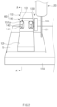
- FIG. 2 is a conceptual front view perspective view of a fixing device for a secondary battery test according to an embodiment of the present invention
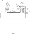
- FIG. 3 is a cross-sectional view taken along line A-A' of FIG. 1 .
- a fixing device 100 for a secondary battery test comprises a seating stage 110 on which a secondary battery 10 is seated, a cover unit 120 covering the secondary battery 10, and a magnetic force generation unit 130 providing magnetic force to the seating stage 110 and the cover unit 120 and fixes the secondary battery 10 so as not to move.
- the fixing device 100 for the secondary battery test according to an embodiment of the present invention may further comprise a vertical moving unit 160 for allowing the cover unit 120 to be coupled to be vertically movable.
- the secondary battery 10 to be tested by using the fixing device for the secondary battery test may comprise a battery case 11 having an accommodation space therein and an electrode assembly 12 accommodated in the accommodation space of the battery case 11.
- the electrode assembly 12 may be a chargeable and dischargeable power generation element and have a structure in which an electrode 12c and a separator 12d are combined and alternately stacked.
- the electrode 12c may comprise a positive electrode 12a and a negative electrode 12b.
- the electrode assembly 12 may have a structure in which the positive electrode 12a/the separator 12d/the negative electrode 12b are alternately stacked.
- the separator 12d may be disposed between the positive electrode 12a and the negative electrode 12b and also disposed outside the positive electrode 12a and outside the negative electrode 12b.
- the separator 12d may be disposed to surround the entire electrode assembly 12 in which the positive electrode 12a/the separator 12d/the negative electrode 12b are stacked.
- the separator 12d is made of an insulation material to electrically insulate the positive electrode 12a from the negative electrode 12b.
- the separator 12d may be made of, for example, a polyolefin-based resin film such as polyethylene or polypropylene having micropores.
- the seating stage 110 may have a planar seating surface to seat the secondary battery 10 for the test thereon.
- the seating stage 110 may have, for example, a rectangular block shape.
- the seating stage 110 is provided as a magnetic body.
- the seating stage 110 is provided as a ferromagnetic body made of a metal material.
- the seating stage 110 may comprise one or more of iron (Fe), nickel (Ni), or cobalt (Co).
- the cover unit 120 is provided as a magnetic body covering the secondary battery 10.
- the cover unit 120 is provided as a ferromagnetic body made of a metal material.
- the cover unit 120 may comprise one or more of iron (Fe), nickel (Ni), or cobalt (Co).
- the cover unit 120 may have, for example, a rectangular block shape.
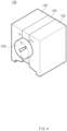
- FIG. 4 is a perspective view of the magnetic force generation unit in the fixing device for the secondary battery test according to an embodiment of the present invention
- FIG. 5 is an exploded perspective view of the magnetic force generation unit in the fixing device for the secondary battery test according to an embodiment of the present invention.
- FIG. 6 is a front view illustrating a state in which magnetism of the magnetic force generation unit 130 is turned off in the fixing device 100 for the secondary battery test according to an embodiment of the present invention
- FIG. 7 is a front view illustrating a state in which the magnetism of the magnetic force generation unit 130 is turned on in the fixing device 100 for the secondary battery test according to an embodiment of the present invention.
- the magnetic force generation unit 130 provides the magnetic force to the seating stage 110 and the cover unit 120.
- attractive magnetic force is generated between the cover unit 120 and the seating stage 110, which receive the magnetic force from the magnetic force generation unit 130 to fix the secondary battery 10 disposed between the cover unit 120 and the seating stage 110 without moving.
- the magnetic force generation unit 130 has one side seated on the seating stage 110 and the other side on which the cover unit 120 is disposed to be vertically movable. Thus, the magnetic force generated in the magnetic force generation unit 130 is transmitted to the seating stage 110 and the cover unit 120.
- the magnetic force generation unit 130 comprises a pair of ferromagnetic blocks 132 and 133, a cylindrical permanent magnet 131 rotatably provided between the pair of ferromagnetic blocks 132 and 133, and a non-magnetic block 134 disposed between the pair of ferromagnetic blocks 132 and 133 to rotatably support the cylindrical permanent magnet 131.
- the magnetic force generation unit 130 may further comprise an adjustment part 135 on an end of the cylindrical permanent magnet 131.
- the ferromagnetic blocks 132 and 133 may be provided in a pair and thus disposed on both sides of the non-magnetic block 134.
- Each of the ferromagnetic blocks 132 and 133 may be made of one or more of Fe, Ni, and Co.
- the non-magnetic block 134 may be made of one or more of aluminum (Al), copper (Cu), and gold (Au).
- Both sides of the cylindrical permanent magnet 131 in a lateral direction of a rotation axis C thereof may respectively have magnetism of an N pole and an S pole, which have opposite polarities.
- the magnetism of the magnetic force generation unit 130 is turned on/off.
- a mounting hole 136 may be formed so that the cylindrical permanent magnet 131 is rotatably mounted over the non-magnetic block 134 and the pair of ferromagnetic blocks 132 and 133.
- the mounting hole 136 may have a shape corresponding to that of the cylindrical permanent magnet 131.
- the cylindrical permanent magnet 131 may rotate along an inner wall of the mounting hole 136 so that both sides of the cylindrical permanent magnet 131 alternately face the non-magnetic block 134 and the pair of ferromagnetic blocks 132 and 133.
- the adjustment part 135 may be disposed on an end of the cylindrical permanent magnet 131 and also disposed outside the mounting hole 136.
- the cylindrical permanent magnet 131 may equally rotate as the adjustment part 135 rotates.
- the adjustment part 135 rotates to allow the cylindrical permanent magnet 131 to rotate, the magnetism of the magnetic force generation unit 130 may be easily turned on/off.
- the adjustment part 135 rotates to allow the cylindrical permanent magnet 131 to rotate, when each of ends 131a and 132b of the N pole and the S pole of the cylindrical permanent magnet 131 is disposed to face the non-magnetic block 134, the magnetism of the magnetic force generation unit 130 may be turned off.
- the adjustment part 135 rotates to allow the cylindrical permanent magnet 131 to rotate, when each of ends 131a and 132b of the N pole and the S pole of the cylindrical permanent magnet 131 is disposed to face the pair of ferromagnetic blocks 132 and133, the magnetism of the magnetic force generation unit 130 may be turned on.
- the ends 131a and 132 of the N pole and the S pole of the cylindrical permanent magnet 131 are respectively disposed to face the pair of ferromagnetic blocks 132 and 133 so that the magnetism of the magnetic force generation unit 130 is turned on to fix the secondary battery 10 through the cover unit 120 and the seating stage 110.
- magnetic force is generated in a direction in which the cover unit 120 and the seating stage 110 are attractive to each other to fix the secondary battery 10.
- the cover unit 120 may be vertically movably coupled to the magnetic force generation unit 130 through the vertical moving unit 160.
- the vertical moving unit 160 may comprise a guide part 150 fixed to the magnetic force generation unit 130 and a movable block 140 coupled to the guide part 150.
- a guide protrusion 151 may protrude from the guide part 150.
- the guide protrusion 151 may protrude in a direction in which the movable block 140 is disposed.
- the movable block 140 may have one side that is vertically movably coupled to the guide part 150 and the other side to which the cover unit 120 is fixed.
- the movable block 140 may have a guide hole 141, into which the guide protrusion 151 is inserted, in a vertical direction. Thus, the movable block 140 may vertically move by being guided by the guide protrusion 151.
- the guide protrusion 151 may comprise a body 151b disposed in the guide hole 141 and an end 151a protruding to the outside of the guide hole 141.
- the end 151a of the guide protrusion 151 may have a size greater than that of the guide hole 141 to prevent the movable block 140 from being separated from the guide part 150.
- the movable block 140 may comprise an accommodation protrusion 142 along an edge of the guide hole 141 so that the end 151a of the guide protrusion 151 is accommodated. That is, a stepped portion may be formed along the edge of the guide hole 141 of the movable block 140 to provide an accommodation part 142 into which the end 151a of the guide protrusion 151 is accommodated.
- the accommodation part 143 into which the end 151a of the guide protrusion 151 is accommodated may have a width corresponding to that of the end 151a of the guide protrusion 151.
- the width of the guide hole 141 may correspond to that of the body 151b of the guide protrusion 151.
- the fixing device 100 for the secondary battery fixes the secondary battery 10 disposed between the cover unit 120 and the seating stage 110 through the attractive magnetic force between the cover unit 120 and the seating stage 110, which receive the magnetic force from the magnetic force generation unit 130.
- movement such as lifting of the secondary battery 10 is suppressed when the nail 21 passes through the secondary battery 10 to prevent secondary short circuit from occurring. That is, when the test in which the nail 21 passes through the secondary battery 10 is performed, the secondary battery 10 may be shaken by an impact to cause the secondary short circuit, thereby significantly deteriorating the reliability with respect to results of the test.
- a secondary battery was fixed by using a fixing device comprising a seating stage provided as a magnetic body, a cover unit provided as a magnetic body and covering the secondary battery, and a magnetic force generation unit, and then, a nail penetration test of the secondary battery was performed.
- the rest conditions are the same as Embodiment 1, except that there is no separate fixing device for fixing the secondary battery.
- FIG. 8 is a cross-sectional view of a fixing device for a secondary battery test according to another embodiment of the present invention
- FIG. 9 is a cross-sectional view of a magnetic force generation unit in the fixing device for the secondary battery test according to another embodiment of the present invention.
- a fixed device 200 for a secondary battery test may comprise a seating stage 110 on which a secondary battery 10 is seated, a cover unit 120 covering the secondary battery 10, a magnetic force generation unit 230 providing magnetic force to the seating stage 110 and cover unit 120, and a moving unit 160 for allowing the cover unit 120 to be coupled to be vertically movable.
- the fixing device 200 for the secondary battery test may comprise non-magnetic bodies 231b and 231c disposed on both sides of a cylindrical permanent magnet 231 of the magnetic force generation unit 230.
- the fixing device 200 for the secondary battery test according to another embodiment of the present invention is different in the configuration of the cylindrical permanent magnet 231 from the fixing device 100 for the secondary battery test according to the foregoing embodiment.
- contents of this embodiment which are duplicated with those according to the forgoing embodiment, will be briefly described, and also, differences therebetween will be mainly described.
- the magnetic force generation unit 230 may comprise a pair of ferromagnetic blocks 232 and 233, a cylindrical permanent magnet 231 rotatably provided between the pair of ferromagnetic blocks 232 and 233, and a non-magnetic block 234 disposed between the pair of ferromagnetic blocks 232 and 233 to rotatably support the cylindrical permanent magnet 231.
- Both sides of the cylindrical permanent magnet 231 in a lateral direction of a rotation axis C thereof may respectively have magnetism of an N pole and an S pole, which have opposite polarities.
- the cylindrical permanent magnet 231 may be divided into, for example, three parts.
- a permanent magnet 231a may be disposed at a central portion of the cylindrical permanent magnet 231, and the non-magnetic bodies 231b and 231c may be respectively disposed on both sides of the permanent magnet 231a.
- the non-magnetic bodies 231b and 231c disposed on both sides of the permanent magnet 231a may face ferromagnetic blocks 232 and 233.
- a more complete non-magnetic state may be easily formed.
- the fixing device for the secondary battery test according to the present invention is not limited thereto. It will be understood by those of ordinary skill in the art that various changes in form and details may be made therein without departing from scope of the invention.
Landscapes
- Engineering & Computer Science (AREA)
- Manufacturing & Machinery (AREA)
- Chemical & Material Sciences (AREA)
- Chemical Kinetics & Catalysis (AREA)
- Electrochemistry (AREA)
- General Chemical & Material Sciences (AREA)
- Mechanical Engineering (AREA)
- Physics & Mathematics (AREA)
- General Physics & Mathematics (AREA)
- Microelectronics & Electronic Packaging (AREA)
- Secondary Cells (AREA)
- Battery Mounting, Suspending (AREA)
- Charge And Discharge Circuits For Batteries Or The Like (AREA)
Claims (11)
- Dispositif de fixation pour un test d'accumulateur, comprenant :un étage de placement sur lequel l'accumulateur à tester est placé et qui est prévu sous la forme d'un corps ferromagnétique constitué d'un matériau métallique ;une unité de recouvrement prévue sous la forme d'un corps ferromagnétique constitué d'un matériau métallique pour recouvrir l'accumulateur ; etune unité de génération de force magnétique fournissant une force magnétique à l'étage de placement et à l'unité de recouvrement et comprenant une paire de blocs ferromagnétiques etun aimant permanent cylindrique prévu de manière rotative entre la paire de blocs ferromagnétiques,dans lequel, pendant la rotation de l'aimant permanent cylindrique, le magnétisme de l'unité de génération de force magnétique est activé/désactivé, et un bloc non magnétique est disposé entre la paire de blocs ferromagnétiques pour supporter de manière rotative l'aimant permanent cylindrique, etdans lequel l'unité de génération de force magnétique présente un côté placé sur l'étage de placement et l'autre côté sur lequel l'unité de recouvrement est prévue pour être verticalement mobile et la force magnétique générée dans la partie de génération de force magnétique est transmise à l'étage de placement et à l'unité de recouvrement ;et dans lequel, lorsque la force magnétique est transmise de l'unité de génération de force magnétique à l'étage de placement et à l'unité de recouvrement, une force magnétique d'attraction est générée entre l'unité de recouvrement et l'unité de placement pour fixer l'accumulateur disposé entre l'unité de recouvrement et l'étage de placement sans mouvement.
- Dispositif de fixation selon la revendication 1, dans lequel un trou de montage est formé de sorte que l'aimant permanent cylindrique soit monté de manière rotative sur le bloc non magnétique et la paire de blocs ferromagnétiques, et
pendant la rotation de l'aimant permanent cylindrique, les deux côtés de l'aimant permanent cylindrique font alternativement face au bloc non magnétique et à la paire de blocs ferromagnétiques. - Dispositif de fixation selon la revendication 1, dans lequel les deux côtés de l'aimant permanent cylindrique dans une direction latérale d'un axe de rotation de celui-ci présentent un magnétisme d'un pôle N et d'un pôle S, qui présentent des polarités opposées.
- Dispositif de fixation selon la revendication 1, dans lequel, pendant la rotation de l'aimant permanent magnétique, lorsque chacune des extrémités des pôles N et S de l'aimant permanent cylindrique est disposée pour faire face au bloc non magnétique, le magnétisme de l'unité de génération de force magnétique est désactivé, et
lorsque les extrémités des pôles N et S de l'aimant permanent cylindrique sont disposées respectivement pour faire face à la paire de blocs ferromagnétiques, le magnétisme de l'unité de génération de force magnétique est activé. - Dispositif de fixation selon la revendication 1, dans lequel chacun des blocs ferromagnétiques comprend un ou plusieurs parmi le Fe, le Ni et le Co.
- Dispositif de fixation selon la revendication 1, dans lequel le bloc non magnétique comprend un ou plusieurs parmi l'Al, le Cu et l'Au.
- Dispositif de fixation selon la revendication 1, dans lequel chacun de l'étage de placement et de l'unité de recouvrement comprend un ou plusieurs parmi le Fe, le Ni et le Co.
- Dispositif de fixation selon la revendication 1, comprenant en outre une unité à mouvement vertical (160) pour permettre à l'unité de recouvrement d'être couplée verticalement de manière mobile à l'unité de génération de force magnétique,
dans lequel l'unité à mouvement vertical comprend :une partie de guidage fixée à l'unité de génération de force magnétique ;un bloc mobile ayant un côté couplé verticalement de manière mobile à la partie de guidage et l'autre côté auquel l'unité de recouvrement est fixée. - Dispositif de fixation selon la revendication 8, dans lequel une saillie de guidage est disposée sur la partie de guidage, et
le bloc mobile présente un trou de guidage, dans lequel la saillie de guidage est insérée, dans une direction verticale de manière à être verticalement mobile en étant guidée par la saillie de guidage. - Dispositif de fixation selon la revendication 9, dans lequel une extrémité de la saillie de guidage a une taille supérieure à une largeur du trou de guidage pour empêcher le bloc mobile d'être séparé de la partie de guidage.
- Dispositif de fixation selon la revendication 10, dans lequel le bloc mobile comprend une saillie de logement le long d'un bord du trou de guidage de sorte que l'extrémité de la saillie de guidage soit logée.
Applications Claiming Priority (3)
| Application Number | Priority Date | Filing Date | Title |
|---|---|---|---|
| KR20170087843 | 2017-07-11 | ||
| KR1020180078398A KR102164255B1 (ko) | 2017-07-11 | 2018-07-05 | 이차전지 시험용 고정장치 |
| PCT/KR2018/007824 WO2019013535A1 (fr) | 2017-07-11 | 2018-07-10 | Dispositif de fixation pour essai d'accumulateur |
Publications (3)
| Publication Number | Publication Date |
|---|---|
| EP3512030A1 EP3512030A1 (fr) | 2019-07-17 |
| EP3512030A4 EP3512030A4 (fr) | 2019-10-30 |
| EP3512030B1 true EP3512030B1 (fr) | 2023-03-29 |
Family
ID=65277812
Family Applications (1)
| Application Number | Title | Priority Date | Filing Date |
|---|---|---|---|
| EP18831175.7A Active EP3512030B1 (fr) | 2017-07-11 | 2018-07-10 | Dispositif de fixation pour essai d'accumulateur |
Country Status (3)
| Country | Link |
|---|---|
| US (1) | US11041909B2 (fr) |
| EP (1) | EP3512030B1 (fr) |
| KR (1) | KR102164255B1 (fr) |
Families Citing this family (4)
| Publication number | Priority date | Publication date | Assignee | Title |
|---|---|---|---|---|
| KR102261757B1 (ko) * | 2020-06-22 | 2021-06-08 | (주) 인텍플러스 | 배터리 전극 검사 시스템 |
| US20230100761A1 (en) * | 2021-09-27 | 2023-03-30 | Lenovo (United States) Inc. | Thermal runaway pin-point heating test |
| KR102699592B1 (ko) * | 2022-08-31 | 2024-08-27 | 김승환 | 수면청소로봇 무선충전장치 |
| CN115508680B (zh) * | 2022-11-09 | 2023-05-02 | 溧阳市明之盛科技有限公司 | 汽车动力电池极柱绝缘检测方法及其装置 |
Family Cites Families (15)
| Publication number | Priority date | Publication date | Assignee | Title |
|---|---|---|---|---|
| JPS61280735A (ja) * | 1985-06-04 | 1986-12-11 | Matsushita Electric Ind Co Ltd | 軸一体成形樹脂磁石回転子の製造方法 |
| KR20010109588A (ko) | 2000-05-31 | 2001-12-12 | 신동희 | 휴대폰용 2차 전지팩의 시험용 지그 |
| JP2006134599A (ja) | 2004-11-02 | 2006-05-25 | Sanyo Electric Co Ltd | 電池モジュールの検査方法と電池モジュール |
| EP2040241B1 (fr) | 2007-09-12 | 2015-12-02 | Shinko Engineering Research Corporation | Système d'expérience et d'éducation employant une pluralité d'unités |
| JP3169620U (ja) | 2011-03-25 | 2011-08-11 | 株式会社山本金属製作所 | 熱伝対付破壊測定器具 |
| KR20130067782A (ko) | 2011-12-14 | 2013-06-25 | 한국항공우주연구원 | 충격 시험기의 릴리즈 장치 |
| KR101528001B1 (ko) | 2012-06-22 | 2015-06-10 | 주식회사 엘지화학 | 이차전지용 전극조립체, 그 제조방법 및 이를 이용한 이차전지 |
| KR102192244B1 (ko) | 2013-12-30 | 2020-12-17 | 삼성디스플레이 주식회사 | 기판 이송장치 |
| US9853267B2 (en) * | 2014-02-03 | 2017-12-26 | Ursatech Ltd. | Intumescent battery housing |
| KR101783921B1 (ko) * | 2014-10-31 | 2017-10-10 | 주식회사 엘지화학 | 전지 평가 장치 |
| KR102308634B1 (ko) | 2015-03-05 | 2021-10-05 | 삼성에스디아이 주식회사 | 이차 전지의 용접용 지그 |
| KR101764299B1 (ko) | 2015-05-06 | 2017-08-03 | 주식회사 엘지화학 | 이차전지 관통 실험용 네일 및 이를 이용한 이차전지 관통 실험 장치 |
| JP2016219267A (ja) | 2015-05-21 | 2016-12-22 | 日本電気株式会社 | 非水電解液二次電池 |
| KR101927257B1 (ko) | 2015-09-09 | 2018-12-10 | 주식회사 엘지화학 | 이차 전지의 못 관통 시험 장치 및 방법 |
| DE102015119434A1 (de) | 2015-11-11 | 2017-05-11 | Airbus Operations Gmbh | Haltevorrichtung, Montagesystem und Verfahren zum Halten von Bauteilen während der Montage |
-
2018
- 2018-07-05 KR KR1020180078398A patent/KR102164255B1/ko active Active
- 2018-07-10 EP EP18831175.7A patent/EP3512030B1/fr active Active
- 2018-07-10 US US16/465,897 patent/US11041909B2/en active Active
Also Published As
| Publication number | Publication date |
|---|---|
| EP3512030A1 (fr) | 2019-07-17 |
| EP3512030A4 (fr) | 2019-10-30 |
| US20190302187A1 (en) | 2019-10-03 |
| US11041909B2 (en) | 2021-06-22 |
| KR102164255B1 (ko) | 2020-10-12 |
| KR20190006913A (ko) | 2019-01-21 |
Similar Documents
| Publication | Publication Date | Title |
|---|---|---|
| US11041909B2 (en) | Fixing device for secondary battery test | |
| US20200189400A1 (en) | Battery module, battery pack comprising battery module, and vehicle comprising battery pack | |
| KR101705308B1 (ko) | 전극 탭 고정 지그 및 이를 포함하는 이차 전지 충방전 장치 | |
| KR101651712B1 (ko) | 이차전지 | |
| KR102245128B1 (ko) | 파우치 성형 장치 및 방법 | |
| US20150214569A1 (en) | Battery module assembly and manufacturing method therefor | |
| US11824152B2 (en) | Apparatus and method for manufacturing unit cell | |
| KR20140036438A (ko) | 이차전지 셀의 이송 캐리어 | |
| KR101888207B1 (ko) | 전지 셀 적층 지그 | |
| JP7037725B2 (ja) | 密閉型電池 | |
| KR20150084270A (ko) | 리튬 이차전지의 제조방법 | |
| JP2018125239A (ja) | 角型二次電池 | |
| US20200168875A1 (en) | Secondary battery | |
| CN107210390B (zh) | 电池单池和电池系统 | |
| KR20240082973A (ko) | 배터리 어셈블리 | |
| US20150255772A1 (en) | Separator for secondary battery electrode assembly and secondary battery including the same | |
| KR101888208B1 (ko) | 전지 셀 적층 지그 | |
| CN109863638B (zh) | 用于二次电池测试的固定装置 | |
| KR102162723B1 (ko) | 절곡된 한 개의 분리막으로 이루어진 단위셀을 포함하고 있는 전극조립체 | |
| KR20160094620A (ko) | 전지셀의 실링부를 절곡하기 위한 장치 | |
| CN107636884B (zh) | 用于运行可充电的电池组电池的方法和电池组控制设备 | |
| JP2022074786A (ja) | 充放電装置の薄型二次電池との接続機構 | |
| KR20210074505A (ko) | 이차전지 | |
| CN113661398B (zh) | 测量单元电芯的性能的方法和测量二次电池的性能的方法 | |
| KR20160087252A (ko) | 이차 전지용 카트리지 및 이를 포함하는 배터리 모듈 |
Legal Events
| Date | Code | Title | Description |
|---|---|---|---|
| STAA | Information on the status of an ep patent application or granted ep patent |
Free format text: STATUS: THE INTERNATIONAL PUBLICATION HAS BEEN MADE |
|
| PUAI | Public reference made under article 153(3) epc to a published international application that has entered the european phase |
Free format text: ORIGINAL CODE: 0009012 |
|
| STAA | Information on the status of an ep patent application or granted ep patent |
Free format text: STATUS: REQUEST FOR EXAMINATION WAS MADE |
|
| 17P | Request for examination filed |
Effective date: 20190410 |
|
| AK | Designated contracting states |
Kind code of ref document: A1 Designated state(s): AL AT BE BG CH CY CZ DE DK EE ES FI FR GB GR HR HU IE IS IT LI LT LU LV MC MK MT NL NO PL PT RO RS SE SI SK SM TR |
|
| AX | Request for extension of the european patent |
Extension state: BA ME |
|
| REG | Reference to a national code |
Ref country code: DE Ref legal event code: R079 Ref document number: 602018047853 Country of ref document: DE Free format text: PREVIOUS MAIN CLASS: H01M0010420000 Ipc: B25B0011000000 |
|
| A4 | Supplementary search report drawn up and despatched |
Effective date: 20190930 |
|
| RIC1 | Information provided on ipc code assigned before grant |
Ipc: B25B 11/00 20060101AFI20190924BHEP Ipc: H01M 10/42 20060101ALI20190924BHEP |
|
| DAV | Request for validation of the european patent (deleted) | ||
| DAX | Request for extension of the european patent (deleted) | ||
| RAP1 | Party data changed (applicant data changed or rights of an application transferred) |
Owner name: LG ENERGY SOLUTION LTD. |
|
| RAP3 | Party data changed (applicant data changed or rights of an application transferred) |
Owner name: LG ENERGY SOLUTION, LTD. |
|
| GRAP | Despatch of communication of intention to grant a patent |
Free format text: ORIGINAL CODE: EPIDOSNIGR1 |
|
| STAA | Information on the status of an ep patent application or granted ep patent |
Free format text: STATUS: GRANT OF PATENT IS INTENDED |
|
| INTG | Intention to grant announced |
Effective date: 20221018 |
|
| GRAS | Grant fee paid |
Free format text: ORIGINAL CODE: EPIDOSNIGR3 |
|
| GRAA | (expected) grant |
Free format text: ORIGINAL CODE: 0009210 |
|
| STAA | Information on the status of an ep patent application or granted ep patent |
Free format text: STATUS: THE PATENT HAS BEEN GRANTED |
|
| AK | Designated contracting states |
Kind code of ref document: B1 Designated state(s): AL AT BE BG CH CY CZ DE DK EE ES FI FR GB GR HR HU IE IS IT LI LT LU LV MC MK MT NL NO PL PT RO RS SE SI SK SM TR |
|
| REG | Reference to a national code |
Ref country code: CH Ref legal event code: EP |
|
| REG | Reference to a national code |
Ref country code: DE Ref legal event code: R096 Ref document number: 602018047853 Country of ref document: DE |
|
| REG | Reference to a national code |
Ref country code: AT Ref legal event code: REF Ref document number: 1556343 Country of ref document: AT Kind code of ref document: T Effective date: 20230415 |
|
| REG | Reference to a national code |
Ref country code: IE Ref legal event code: FG4D |
|
| REG | Reference to a national code |
Ref country code: LT Ref legal event code: MG9D |
|
| PG25 | Lapsed in a contracting state [announced via postgrant information from national office to epo] |
Ref country code: RS Free format text: LAPSE BECAUSE OF FAILURE TO SUBMIT A TRANSLATION OF THE DESCRIPTION OR TO PAY THE FEE WITHIN THE PRESCRIBED TIME-LIMIT Effective date: 20230329 Ref country code: NO Free format text: LAPSE BECAUSE OF FAILURE TO SUBMIT A TRANSLATION OF THE DESCRIPTION OR TO PAY THE FEE WITHIN THE PRESCRIBED TIME-LIMIT Effective date: 20230629 Ref country code: LV Free format text: LAPSE BECAUSE OF FAILURE TO SUBMIT A TRANSLATION OF THE DESCRIPTION OR TO PAY THE FEE WITHIN THE PRESCRIBED TIME-LIMIT Effective date: 20230329 Ref country code: LT Free format text: LAPSE BECAUSE OF FAILURE TO SUBMIT A TRANSLATION OF THE DESCRIPTION OR TO PAY THE FEE WITHIN THE PRESCRIBED TIME-LIMIT Effective date: 20230329 Ref country code: HR Free format text: LAPSE BECAUSE OF FAILURE TO SUBMIT A TRANSLATION OF THE DESCRIPTION OR TO PAY THE FEE WITHIN THE PRESCRIBED TIME-LIMIT Effective date: 20230329 |
|
| REG | Reference to a national code |
Ref country code: NL Ref legal event code: MP Effective date: 20230329 |
|
| REG | Reference to a national code |
Ref country code: AT Ref legal event code: MK05 Ref document number: 1556343 Country of ref document: AT Kind code of ref document: T Effective date: 20230329 |
|
| PG25 | Lapsed in a contracting state [announced via postgrant information from national office to epo] |
Ref country code: SE Free format text: LAPSE BECAUSE OF FAILURE TO SUBMIT A TRANSLATION OF THE DESCRIPTION OR TO PAY THE FEE WITHIN THE PRESCRIBED TIME-LIMIT Effective date: 20230329 Ref country code: NL Free format text: LAPSE BECAUSE OF FAILURE TO SUBMIT A TRANSLATION OF THE DESCRIPTION OR TO PAY THE FEE WITHIN THE PRESCRIBED TIME-LIMIT Effective date: 20230329 Ref country code: GR Free format text: LAPSE BECAUSE OF FAILURE TO SUBMIT A TRANSLATION OF THE DESCRIPTION OR TO PAY THE FEE WITHIN THE PRESCRIBED TIME-LIMIT Effective date: 20230630 Ref country code: FI Free format text: LAPSE BECAUSE OF FAILURE TO SUBMIT A TRANSLATION OF THE DESCRIPTION OR TO PAY THE FEE WITHIN THE PRESCRIBED TIME-LIMIT Effective date: 20230329 |
|
| PG25 | Lapsed in a contracting state [announced via postgrant information from national office to epo] |
Ref country code: SM Free format text: LAPSE BECAUSE OF FAILURE TO SUBMIT A TRANSLATION OF THE DESCRIPTION OR TO PAY THE FEE WITHIN THE PRESCRIBED TIME-LIMIT Effective date: 20230329 Ref country code: RO Free format text: LAPSE BECAUSE OF FAILURE TO SUBMIT A TRANSLATION OF THE DESCRIPTION OR TO PAY THE FEE WITHIN THE PRESCRIBED TIME-LIMIT Effective date: 20230329 Ref country code: PT Free format text: LAPSE BECAUSE OF FAILURE TO SUBMIT A TRANSLATION OF THE DESCRIPTION OR TO PAY THE FEE WITHIN THE PRESCRIBED TIME-LIMIT Effective date: 20230731 Ref country code: ES Free format text: LAPSE BECAUSE OF FAILURE TO SUBMIT A TRANSLATION OF THE DESCRIPTION OR TO PAY THE FEE WITHIN THE PRESCRIBED TIME-LIMIT Effective date: 20230329 Ref country code: EE Free format text: LAPSE BECAUSE OF FAILURE TO SUBMIT A TRANSLATION OF THE DESCRIPTION OR TO PAY THE FEE WITHIN THE PRESCRIBED TIME-LIMIT Effective date: 20230329 Ref country code: AT Free format text: LAPSE BECAUSE OF FAILURE TO SUBMIT A TRANSLATION OF THE DESCRIPTION OR TO PAY THE FEE WITHIN THE PRESCRIBED TIME-LIMIT Effective date: 20230329 |
|
| PG25 | Lapsed in a contracting state [announced via postgrant information from national office to epo] |
Ref country code: SK Free format text: LAPSE BECAUSE OF FAILURE TO SUBMIT A TRANSLATION OF THE DESCRIPTION OR TO PAY THE FEE WITHIN THE PRESCRIBED TIME-LIMIT Effective date: 20230329 Ref country code: PL Free format text: LAPSE BECAUSE OF FAILURE TO SUBMIT A TRANSLATION OF THE DESCRIPTION OR TO PAY THE FEE WITHIN THE PRESCRIBED TIME-LIMIT Effective date: 20230329 Ref country code: IS Free format text: LAPSE BECAUSE OF FAILURE TO SUBMIT A TRANSLATION OF THE DESCRIPTION OR TO PAY THE FEE WITHIN THE PRESCRIBED TIME-LIMIT Effective date: 20230729 |
|
| REG | Reference to a national code |
Ref country code: DE Ref legal event code: R097 Ref document number: 602018047853 Country of ref document: DE |
|
| PG25 | Lapsed in a contracting state [announced via postgrant information from national office to epo] |
Ref country code: DK Free format text: LAPSE BECAUSE OF FAILURE TO SUBMIT A TRANSLATION OF THE DESCRIPTION OR TO PAY THE FEE WITHIN THE PRESCRIBED TIME-LIMIT Effective date: 20230329 Ref country code: CZ Free format text: LAPSE BECAUSE OF FAILURE TO SUBMIT A TRANSLATION OF THE DESCRIPTION OR TO PAY THE FEE WITHIN THE PRESCRIBED TIME-LIMIT Effective date: 20230329 |
|
| PLBE | No opposition filed within time limit |
Free format text: ORIGINAL CODE: 0009261 |
|
| STAA | Information on the status of an ep patent application or granted ep patent |
Free format text: STATUS: NO OPPOSITION FILED WITHIN TIME LIMIT |
|
| PG25 | Lapsed in a contracting state [announced via postgrant information from national office to epo] |
Ref country code: MC Free format text: LAPSE BECAUSE OF FAILURE TO SUBMIT A TRANSLATION OF THE DESCRIPTION OR TO PAY THE FEE WITHIN THE PRESCRIBED TIME-LIMIT Effective date: 20230329 |
|
| PG25 | Lapsed in a contracting state [announced via postgrant information from national office to epo] |
Ref country code: MC Free format text: LAPSE BECAUSE OF FAILURE TO SUBMIT A TRANSLATION OF THE DESCRIPTION OR TO PAY THE FEE WITHIN THE PRESCRIBED TIME-LIMIT Effective date: 20230329 |
|
| REG | Reference to a national code |
Ref country code: CH Ref legal event code: PL |
|
| 26N | No opposition filed |
Effective date: 20240103 |
|
| REG | Reference to a national code |
Ref country code: BE Ref legal event code: MM Effective date: 20230731 |
|
| PG25 | Lapsed in a contracting state [announced via postgrant information from national office to epo] |
Ref country code: LU Free format text: LAPSE BECAUSE OF NON-PAYMENT OF DUE FEES Effective date: 20230710 |
|
| PG25 | Lapsed in a contracting state [announced via postgrant information from national office to epo] |
Ref country code: LU Free format text: LAPSE BECAUSE OF NON-PAYMENT OF DUE FEES Effective date: 20230710 |
|
| REG | Reference to a national code |
Ref country code: IE Ref legal event code: MM4A |
|
| PG25 | Lapsed in a contracting state [announced via postgrant information from national office to epo] |
Ref country code: CH Free format text: LAPSE BECAUSE OF NON-PAYMENT OF DUE FEES Effective date: 20230731 |
|
| PG25 | Lapsed in a contracting state [announced via postgrant information from national office to epo] |
Ref country code: SI Free format text: LAPSE BECAUSE OF FAILURE TO SUBMIT A TRANSLATION OF THE DESCRIPTION OR TO PAY THE FEE WITHIN THE PRESCRIBED TIME-LIMIT Effective date: 20230329 |
|
| PG25 | Lapsed in a contracting state [announced via postgrant information from national office to epo] |
Ref country code: SI Free format text: LAPSE BECAUSE OF FAILURE TO SUBMIT A TRANSLATION OF THE DESCRIPTION OR TO PAY THE FEE WITHIN THE PRESCRIBED TIME-LIMIT Effective date: 20230329 Ref country code: IT Free format text: LAPSE BECAUSE OF FAILURE TO SUBMIT A TRANSLATION OF THE DESCRIPTION OR TO PAY THE FEE WITHIN THE PRESCRIBED TIME-LIMIT Effective date: 20230329 Ref country code: BE Free format text: LAPSE BECAUSE OF NON-PAYMENT OF DUE FEES Effective date: 20230731 |
|
| PG25 | Lapsed in a contracting state [announced via postgrant information from national office to epo] |
Ref country code: IE Free format text: LAPSE BECAUSE OF NON-PAYMENT OF DUE FEES Effective date: 20230710 |
|
| PG25 | Lapsed in a contracting state [announced via postgrant information from national office to epo] |
Ref country code: IE Free format text: LAPSE BECAUSE OF NON-PAYMENT OF DUE FEES Effective date: 20230710 |
|
| PG25 | Lapsed in a contracting state [announced via postgrant information from national office to epo] |
Ref country code: BG Free format text: LAPSE BECAUSE OF FAILURE TO SUBMIT A TRANSLATION OF THE DESCRIPTION OR TO PAY THE FEE WITHIN THE PRESCRIBED TIME-LIMIT Effective date: 20230329 |
|
| P01 | Opt-out of the competence of the unified patent court (upc) registered |
Free format text: CASE NUMBER: APP_53508/2024 Effective date: 20240926 |
|
| PG25 | Lapsed in a contracting state [announced via postgrant information from national office to epo] |
Ref country code: BG Free format text: LAPSE BECAUSE OF FAILURE TO SUBMIT A TRANSLATION OF THE DESCRIPTION OR TO PAY THE FEE WITHIN THE PRESCRIBED TIME-LIMIT Effective date: 20230329 |
|
| PGFP | Annual fee paid to national office [announced via postgrant information from national office to epo] |
Ref country code: GB Payment date: 20250624 Year of fee payment: 8 |
|
| PGFP | Annual fee paid to national office [announced via postgrant information from national office to epo] |
Ref country code: FR Payment date: 20250624 Year of fee payment: 8 |
|
| PG25 | Lapsed in a contracting state [announced via postgrant information from national office to epo] |
Ref country code: CY Free format text: LAPSE BECAUSE OF FAILURE TO SUBMIT A TRANSLATION OF THE DESCRIPTION OR TO PAY THE FEE WITHIN THE PRESCRIBED TIME-LIMIT; INVALID AB INITIO Effective date: 20180710 |
|
| PG25 | Lapsed in a contracting state [announced via postgrant information from national office to epo] |
Ref country code: HU Free format text: LAPSE BECAUSE OF FAILURE TO SUBMIT A TRANSLATION OF THE DESCRIPTION OR TO PAY THE FEE WITHIN THE PRESCRIBED TIME-LIMIT; INVALID AB INITIO Effective date: 20180710 |
|
| PGFP | Annual fee paid to national office [announced via postgrant information from national office to epo] |
Ref country code: DE Payment date: 20250624 Year of fee payment: 8 |
|
| PG25 | Lapsed in a contracting state [announced via postgrant information from national office to epo] |
Ref country code: TR Free format text: LAPSE BECAUSE OF FAILURE TO SUBMIT A TRANSLATION OF THE DESCRIPTION OR TO PAY THE FEE WITHIN THE PRESCRIBED TIME-LIMIT Effective date: 20230329 |