EP3512058A1 - Chaîne de protection de câble - Google Patents
Chaîne de protection de câble Download PDFInfo
- Publication number
- EP3512058A1 EP3512058A1 EP18211345.6A EP18211345A EP3512058A1 EP 3512058 A1 EP3512058 A1 EP 3512058A1 EP 18211345 A EP18211345 A EP 18211345A EP 3512058 A1 EP3512058 A1 EP 3512058A1
- Authority
- EP
- European Patent Office
- Prior art keywords
- cable
- sidewalls
- protective device
- floor
- opposed
- Prior art date
- Legal status (The legal status is an assumption and is not a legal conclusion. Google has not performed a legal analysis and makes no representation as to the accuracy of the status listed.)
- Withdrawn
Links
- 230000001681 protective effect Effects 0.000 claims abstract description 27
- 239000011800 void material Substances 0.000 claims abstract description 15
- 229910052751 metal Inorganic materials 0.000 claims description 7
- 239000002184 metal Substances 0.000 claims description 7
- 229920000642 polymer Polymers 0.000 claims description 6
- -1 polypropylene Polymers 0.000 claims description 4
- 239000004698 Polyethylene Substances 0.000 claims description 2
- 239000004743 Polypropylene Substances 0.000 claims description 2
- 229920000573 polyethylene Polymers 0.000 claims description 2
- 229920001155 polypropylene Polymers 0.000 claims description 2
- 230000015572 biosynthetic process Effects 0.000 abstract 1
- 239000004020 conductor Substances 0.000 description 8
- XEEYBQQBJWHFJM-UHFFFAOYSA-N Iron Chemical compound [Fe] XEEYBQQBJWHFJM-UHFFFAOYSA-N 0.000 description 4
- 229910045601 alloy Inorganic materials 0.000 description 4
- 239000000956 alloy Substances 0.000 description 4
- 238000000034 method Methods 0.000 description 3
- 230000003287 optical effect Effects 0.000 description 3
- 239000004033 plastic Substances 0.000 description 3
- 229920003023 plastic Polymers 0.000 description 3
- 230000002028 premature Effects 0.000 description 3
- 230000001012 protector Effects 0.000 description 3
- 229910052782 aluminium Inorganic materials 0.000 description 2
- XAGFODPZIPBFFR-UHFFFAOYSA-N aluminium Chemical compound [Al] XAGFODPZIPBFFR-UHFFFAOYSA-N 0.000 description 2
- 238000010276 construction Methods 0.000 description 2
- 229910052742 iron Inorganic materials 0.000 description 2
- 230000000717 retained effect Effects 0.000 description 2
- JHWNWJKBPDFINM-UHFFFAOYSA-N Laurolactam Chemical compound O=C1CCCCCCCCCCCN1 JHWNWJKBPDFINM-UHFFFAOYSA-N 0.000 description 1
- 229920000299 Nylon 12 Polymers 0.000 description 1
- 239000002131 composite material Substances 0.000 description 1
- 239000000463 material Substances 0.000 description 1
- 150000002739 metals Chemical class 0.000 description 1
- 229920001778 nylon Polymers 0.000 description 1
Images


Classifications
-
- H—ELECTRICITY
- H02—GENERATION; CONVERSION OR DISTRIBUTION OF ELECTRIC POWER
- H02G—INSTALLATION OF ELECTRIC CABLES OR LINES, OR OF COMBINED OPTICAL AND ELECTRIC CABLES OR LINES
- H02G11/00—Arrangements of electric cables or lines between relatively-movable parts
- H02G11/006—Arrangements of electric cables or lines between relatively-movable parts using extensible carrier for the cable, e.g. self-coiling spring
-
- F—MECHANICAL ENGINEERING; LIGHTING; HEATING; WEAPONS; BLASTING
- F16—ENGINEERING ELEMENTS AND UNITS; GENERAL MEASURES FOR PRODUCING AND MAINTAINING EFFECTIVE FUNCTIONING OF MACHINES OR INSTALLATIONS; THERMAL INSULATION IN GENERAL
- F16G—BELTS, CABLES, OR ROPES, PREDOMINANTLY USED FOR DRIVING PURPOSES; CHAINS; FITTINGS PREDOMINANTLY USED THEREFOR
- F16G13/00—Chains
- F16G13/12—Hauling- or hoisting-chains so called ornamental chains
- F16G13/16—Hauling- or hoisting-chains so called ornamental chains with arrangements for holding electric cables, hoses, or the like
-
- H—ELECTRICITY
- H02—GENERATION; CONVERSION OR DISTRIBUTION OF ELECTRIC POWER
- H02G—INSTALLATION OF ELECTRIC CABLES OR LINES, OR OF COMBINED OPTICAL AND ELECTRIC CABLES OR LINES
- H02G3/00—Installations of electric cables or lines or protective tubing therefor in or on buildings, equivalent structures or vehicles
- H02G3/02—Details
- H02G3/04—Protective tubing or conduits, e.g. cable ladders or cable troughs
- H02G3/0406—Details thereof
- H02G3/0418—Covers or lids; Their fastenings
-
- H—ELECTRICITY
- H02—GENERATION; CONVERSION OR DISTRIBUTION OF ELECTRIC POWER
- H02G—INSTALLATION OF ELECTRIC CABLES OR LINES, OR OF COMBINED OPTICAL AND ELECTRIC CABLES OR LINES
- H02G3/00—Installations of electric cables or lines or protective tubing therefor in or on buildings, equivalent structures or vehicles
- H02G3/02—Details
- H02G3/04—Protective tubing or conduits, e.g. cable ladders or cable troughs
- H02G3/0462—Tubings, i.e. having a closed section
- H02G3/0475—Tubings, i.e. having a closed section formed by a succession of articulated units
Definitions
- a retaining element such as L-shaped or C-shape parts are provided on a radius area of the cable chain to protect the cable contained therein.
- the retaining element is tethered to the protective cable chain, and in some embodiments, is hingedly connected to the protective cable chain.
- the relatively moving parts may be part of the same machine, may be located on different machines, or may extend between a fixed element and a moving part.
- a chain protector comprising interconnected chain links into which the cable will rest.
- the cable can be any type of cable, such as one bearing one or more electrical conductors or optical conductors; and combinations thereof; and may have the conductors arranged in twisted, braided, concentric or other configurations.
- the links may comprise two parallel sidewalls having a bottom wall connected to, and spacing the sidewalls from one another, to form a void therebetween.
- a plurality of similar links may be interconnected so as to form a chain having a continuous void therein.
- the cable is situated so as to be protected on three sides by the two spaced sidewalls and the bottom wall.
- the chain so formed may be advanced or retracted by driving with a cog or chain gear, as the respectively moving parts which are connected to the cable relatively move in relation to one another, or may just flex without any driving mechanism.
- a retaining element which can take the shape of a C- or an L-shaped element, which is designed to bridge the open end of the two parallel sidewalls of the chain opposite the bottom wall is provided.
- the retaining element associated with the links that made up the protective cable chain.
- the C- or the L-shaped element is integrally connected to one of the sidewalls by a tether.
- the retaining element, in the form of the L-shaped element is hingedly connected by a living hinge, such that the L-shaped element may be rotated about the living hinge thousands, and up-to hundreds-of-thousands of times, without failure.
- the distal ends of the C-shaped element; or at least one end of the L-shaped element, opposite the hinge side is provided with an element to interlock the retaining element with one, or both of the sidewalls, so as to remain in a closed, locked position to secure the cable within the void bounded by the two parallel sidewalls, the bottom wall, and the retaining element.
- the link comprises a polymeric material, which is molded to shape, so as to provide the L-shaped element as an integral part of one of the sidewalls.
- FIG. 1 shows the combination of a cable and protective chain 10.
- Cable 12 is shown with multiple conductors 13, 14, 15, 16 and 17, each terminating in a plug 18, 19, 20, 21 and 22, respectively. This arrangement of the cable 12 is for illustrative purposes only and should not be viewed as limiting.
- the cable 12 may take other forms, such as having fewer or more conductors, the presence or absence of plugs, sockets, or other terminal endings.
- the cable 12 may also be formed of electrical conductors, such as metallic wires, optical connectors, for example light pipes, or other forms of optical conductors, and combinations thereof.
- FIG. 1 also illustrates a cable chain 24, with the cable 12 contained in a void formed by various elements of the cable chain 24.
- the area A may be formed as a radius.
- the radius "r” may be about a cog or chain gear (not shown) or a natural radius "r” formed in the absence of a cog or chain gear as when the relative movement of the two parts between which the cable chain and cable contained therein forms such a radius "r".
- each link can be formed of metal, plastic, or composite construction.
- Plastics can be selected from any suitable polymer, such as polypropylene or polyethylene; nylons, such as Nylon 12; as well as other suitable plastics.
- metals, iron and its alloys, aluminum and its alloys can be used.
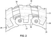
- each link comprise a retaining element, such as the L-shaped element 30, it is not required that each link be provided with a retaining element, especially where the cable chain is of extended length.
- FIG. 3 is an enlarged view of a portion of FIG. 2 to show more detail of the link construction.
- Link 27 comprises two upstanding sidewalls 32, 34 joined together by floor 35.
- Floor 35 both positions sidewalls 32, 34 in relation to each other, and also positions sidewalls 32, 34 generally orthogonal to the floor.
- the cable chain 24 might provide some protection to a cable inserted into a void formed between sidewalls 32, 34 and floor 35, a cable placed therein is prone to damage by not being retained in such void between sidewalls 32, 34 and floor 35.
- a retaining element shown as L-shaped element 30, is provided to secure the cable within the void to prevent the possibility of damage to the cable during flexing thereof.
- the retaining element illustrated as the L-shaped element 30, may be attached to one of the sidewalls, here 32, so as to be pivotably moveable with regard to the sidewall 32 by reason of hinges 36, 37 at the juncture of L-shaped element 30 with the sidewall 32.
- Hinges 36, 37 are of the so-called “butterfly" hinge design to assure bi-stable pivot action, although other hinge forms may be substituted. If the sidewall 32 and L-shaped element 30 are formed of a molded polymer, the hinges 36, 37 may be integrally formed with the sidewall 32 and L-shaped element 30 into what is known in the art as a "living hinge.”
- a living hinge has an exceptionally long lifespan of thousands, if not hundreds-of-thousands, of rotations before failure.
- a locking element may be provided at the end of L-shaped element 30 distal to the hinge.
- locking element 38 is provided as a boss which is designed to interfit into groove 39 on the sidewall 34.
- L-shaped element 30 When rotated about hinges 36, 37 on the sidewall 32, L-shaped element 30 will lock with the sidewall 34, as shown in transparent portion of FIG. 2 by means of locking element 38 locking into groove 39 on the sidewall 34.
- boss and groove may be interchanged without departing from the teachings of a lock.
- alternative elements may be substituted for the boss and groove in order to lock the L-shaped element to the sidewall.
- the retaining element may also take the form of a C-shaped element, with locking elements on each end of the C-shape so as to lock with each of sidewalls 32 and 34 as the C-shape bridges the open end of sidewalls 32, 34.
- the retaining element for example L-shaped element 30 completes the capture of cable 12 in the void formed between sidewalls 32, 34 on the one hand and floor 35 and L-shaped element 30 on the other hand.
- the retaining element in the form of a C-shaped element, can be locked into place with each or sidewalls 32, 34, thereby also capturing cable 12 in the void formed between the opposed sidewalls 32, 34, floor 35 and the opposed retaining element 30.
- Cable 12 is now safely secured within the cable chain 24 and protected from impingement on the relatively moving parts; or other stationary part during advancement; or retraction of the relatively moving parts; or from premature flexing of the cable; or otherwise lifting of the cable from the cable chain protector.
- Holes 40, 41 may be provided in each of sidewalls 32, 34, respectively for the purpose of permitting pins (only one of which is shown) at 42 from an adjacent link to interfit into its respective hole 40, 41 to secure the links together.
- Pin 42 may be formed of the same types of polymers used to form the individual links.
- Other manners of linking the individual links may be provided, such as a single pin that engages with each of holes 40, 41. However, the use of a single pin which bridges holes 40, 41 would diminish the area of the void into which the cable 12 must fit. Therefore, it is not preferred.
- the individual links 26, 27, 28, etc. are formed of metal, the pins may be formed as rivets.
- L-shaped member 30 may also be formed of metal and in that instance, hinges 36, 37 may comprise ordinary hinge pins.
- a stopper 31 is provided so as to limit the degree of rotation of each link with its adjacent link, so as to prevent excessive degree of rotation of the cable chain 24 upon itself and thereby preventing damage to the cable 12 contained therein.
Landscapes
- Engineering & Computer Science (AREA)
- General Engineering & Computer Science (AREA)
- Mechanical Engineering (AREA)
- Electric Cable Arrangement Between Relatively Moving Parts (AREA)
- Architecture (AREA)
- Civil Engineering (AREA)
- Structural Engineering (AREA)
- Details Of Indoor Wiring (AREA)
Applications Claiming Priority (2)
| Application Number | Priority Date | Filing Date | Title |
|---|---|---|---|
| US201862616630P | 2018-01-12 | 2018-01-12 | |
| US15/960,943 US10823256B2 (en) | 2018-01-12 | 2018-04-24 | Cable protection chain |
Publications (1)
| Publication Number | Publication Date |
|---|---|
| EP3512058A1 true EP3512058A1 (fr) | 2019-07-17 |
Family
ID=64664164
Family Applications (1)
| Application Number | Title | Priority Date | Filing Date |
|---|---|---|---|
| EP18211345.6A Withdrawn EP3512058A1 (fr) | 2018-01-12 | 2018-12-10 | Chaîne de protection de câble |
Country Status (5)
| Country | Link |
|---|---|
| US (1) | US10823256B2 (fr) |
| EP (1) | EP3512058A1 (fr) |
| JP (1) | JP2019124352A (fr) |
| CN (1) | CN110030328A (fr) |
| TW (1) | TW201930750A (fr) |
Families Citing this family (8)
| Publication number | Priority date | Publication date | Assignee | Title |
|---|---|---|---|---|
| EP3591776B1 (fr) * | 2018-07-05 | 2022-01-05 | TRUMPF Medizin Systeme GmbH + Co. KG | Système de routage de câble |
| CN111168729A (zh) * | 2020-01-09 | 2020-05-19 | 杨西望 | 一种往复数据活动定位运动控制系统 |
| JP7625580B2 (ja) * | 2020-03-25 | 2025-02-03 | 日本キヤリア株式会社 | 配線保護構造、および空気調和機の室内ユニット |
| TWI895428B (zh) * | 2020-05-27 | 2025-09-01 | 德商易格斯股份有限公司 | 具有可撓性接頭連接器的拖鏈,以及用於該拖鏈的側板和接頭連接器 |
| KR102443329B1 (ko) * | 2020-05-28 | 2022-09-15 | 주식회사 이엘코퍼레이션 | 케이블 체인 |
| DE202020105121U1 (de) * | 2020-09-04 | 2021-10-07 | Igus Gmbh | Teilungssteg zur Innenaufteilung einer Energieführungskette |
| DE202021101925U1 (de) | 2021-04-09 | 2022-08-25 | Igus Gmbh | Energieführungskette mit Gleitkufe und nachrüstbare Gleitkufe hierfür |
| DE202021104228U1 (de) * | 2021-08-06 | 2022-09-07 | Igus Gmbh | System zur Abstützung einer beweglichen Leitungsaufnahmeeinrichtung, Energieführungskette oder dgl. |
Citations (7)
| Publication number | Priority date | Publication date | Assignee | Title |
|---|---|---|---|---|
| DE3714056C1 (en) * | 1987-04-28 | 1988-08-25 | Murr Plastik Gmbh | Energy management chain |
| JPH1028310A (ja) * | 1996-07-05 | 1998-01-27 | Aiwa Sangyo Kk | ケーブル類の移動案内装置 |
| WO1998040644A1 (fr) * | 1997-03-13 | 1998-09-17 | Kabelschlepp Gmbh | Element de protection muni d'un couvercle pouvant etre place dans deux differentes positions stables |
| EP1010558A2 (fr) * | 1998-12-15 | 2000-06-21 | DaimlerChrysler Corporation | Système de porte glissante pour véhicules |
| US20030145575A1 (en) * | 2002-02-05 | 2003-08-07 | Mendenhall Jefferson S. | Chain links and cable carrier chains containing same |
| US20170037985A1 (en) * | 2015-08-04 | 2017-02-09 | Lite-On Electronics (Guangzhou) Limited | Chain and chain device |
| US20170108082A1 (en) * | 2014-03-24 | 2017-04-20 | Igus Gmbh | Line guide device with one-piece hinge, a corresponding chain link and a hinge band |
Family Cites Families (12)
| Publication number | Priority date | Publication date | Assignee | Title |
|---|---|---|---|---|
| DE7800098U1 (de) | 1978-01-03 | 1978-05-18 | Rehau Plastiks Ag & Co, 8673 Rehau | Leitungskanal aus Kunststoff für Kabel |
| DE3318365A1 (de) * | 1983-05-20 | 1984-11-22 | Kabelschlepp Gmbh, 5900 Siegen | Energiefuehrungskette |
| DE10118328A1 (de) * | 2001-04-12 | 2002-11-21 | Kabelschlepp Gmbh | Verfahren zur Herstellung eines Kettengliedes sowie Kettenglied einer Energieführungskette |
| DE102004022512A1 (de) * | 2004-05-05 | 2005-12-01 | Kabelschlepp Gmbh | Kettenglied für eine Energieführungskette sowie Energieführungskette mit erweitertem Nutzungsquerschnitt |
| JP4476204B2 (ja) * | 2005-09-29 | 2010-06-09 | 株式会社椿本チエイン | ケーブル類保護案内装置 |
| JP4722207B2 (ja) | 2009-08-06 | 2011-07-13 | 株式会社椿本チエイン | ケーブル類保護案内装置 |
| DE202011004785U1 (de) * | 2011-04-01 | 2011-07-07 | igus GmbH, 51147 | Energieführungskette mit deformierbaren Gelenkelementen |
| DE202011101573U1 (de) * | 2011-05-30 | 2012-09-04 | Tsubaki Kabelschlepp GmbH | Bauteil für ein Leitungsführungssystem umfassend zumindest eine Leitungsführungseinrichtung sowie eine entsprechende Leitungsführungseinrichtung und Leitungsführungssystem |
| TWM427481U (en) * | 2011-12-26 | 2012-04-21 | Kang Yang Hardware Entpr Co Ltd | Guiding protection device for cable and pipe |
| JP6060064B2 (ja) * | 2013-11-11 | 2017-01-11 | 株式会社椿本チエイン | ケーブル類保護案内装置 |
| DE202014104075U1 (de) * | 2014-09-01 | 2014-09-09 | Igus Gmbh | Leitungsführungseinrichtung |
| CN206246603U (zh) * | 2016-11-24 | 2017-06-13 | 立讯精密工业股份有限公司 | 拖链 |
-
2018
- 2018-04-24 US US15/960,943 patent/US10823256B2/en active Active
- 2018-10-25 TW TW107137827A patent/TW201930750A/zh unknown
- 2018-11-07 CN CN201811317295.XA patent/CN110030328A/zh active Pending
- 2018-12-10 EP EP18211345.6A patent/EP3512058A1/fr not_active Withdrawn
- 2018-12-28 JP JP2018247141A patent/JP2019124352A/ja active Pending
Patent Citations (7)
| Publication number | Priority date | Publication date | Assignee | Title |
|---|---|---|---|---|
| DE3714056C1 (en) * | 1987-04-28 | 1988-08-25 | Murr Plastik Gmbh | Energy management chain |
| JPH1028310A (ja) * | 1996-07-05 | 1998-01-27 | Aiwa Sangyo Kk | ケーブル類の移動案内装置 |
| WO1998040644A1 (fr) * | 1997-03-13 | 1998-09-17 | Kabelschlepp Gmbh | Element de protection muni d'un couvercle pouvant etre place dans deux differentes positions stables |
| EP1010558A2 (fr) * | 1998-12-15 | 2000-06-21 | DaimlerChrysler Corporation | Système de porte glissante pour véhicules |
| US20030145575A1 (en) * | 2002-02-05 | 2003-08-07 | Mendenhall Jefferson S. | Chain links and cable carrier chains containing same |
| US20170108082A1 (en) * | 2014-03-24 | 2017-04-20 | Igus Gmbh | Line guide device with one-piece hinge, a corresponding chain link and a hinge band |
| US20170037985A1 (en) * | 2015-08-04 | 2017-02-09 | Lite-On Electronics (Guangzhou) Limited | Chain and chain device |
Also Published As
| Publication number | Publication date |
|---|---|
| US20190219135A1 (en) | 2019-07-18 |
| JP2019124352A (ja) | 2019-07-25 |
| TW201930750A (zh) | 2019-08-01 |
| US10823256B2 (en) | 2020-11-03 |
| CN110030328A (zh) | 2019-07-19 |
Similar Documents
| Publication | Publication Date | Title |
|---|---|---|
| EP3512058A1 (fr) | Chaîne de protection de câble | |
| KR101515742B1 (ko) | 에너지 유도 체인 | |
| CN102913590B (zh) | 线缆类保护引导装置 | |
| DE60209644T2 (de) | Schutzabdeckung für einen Batterieverbindungsabschnitt | |
| RU2160399C2 (ru) | Направляющая цепь для энергетических линий | |
| US7591128B2 (en) | Cable protection and guide device | |
| US7520122B2 (en) | Cable protection and guide device | |
| US9150168B2 (en) | Sliding door wire harness routing structure | |
| US7204075B2 (en) | Cable or the like protection and guide device | |
| EP2975699B1 (fr) | Partie de boîtier pour connecteur électrique enfichable | |
| US9819112B2 (en) | Retaining block and modular plug insert | |
| US6641423B1 (en) | Anchoring system for box of connectors mounted in service boxes | |
| US6029437A (en) | Cable/hose handling chain | |
| US9199105B1 (en) | Safety hook | |
| US11118720B2 (en) | Cable protector | |
| US11898621B2 (en) | Wire guide device having link members surrounding wire | |
| MX2008012440A (es) | Ensamble de conector electrico con auxiliar de empalme y una cubierta de funda de alambre. | |
| EP3436655B1 (fr) | Raccord de liaison | |
| WO2015198126A1 (fr) | Dispositif de chaîne de gainage | |
| KR20140081667A (ko) | 케이블류 보호안내장치 | |
| US20180283427A1 (en) | Link extension connector | |
| ES2539949T3 (es) | Conector eléctrico que tiene una palanca con escudo protector | |
| US20220397214A1 (en) | Guiding device for long object | |
| US7119273B2 (en) | Cables or the like protection and guide device | |
| US9865975B2 (en) | Hinged connector door assembly |
Legal Events
| Date | Code | Title | Description |
|---|---|---|---|
| PUAI | Public reference made under article 153(3) epc to a published international application that has entered the european phase |
Free format text: ORIGINAL CODE: 0009012 |
|
| AK | Designated contracting states |
Kind code of ref document: A1 Designated state(s): AL AT BE BG CH CY CZ DE DK EE ES FI FR GB GR HR HU IE IS IT LI LT LU LV MC MK MT NL NO PL PT RO RS SE SI SK SM TR |
|
| AX | Request for extension of the european patent |
Extension state: BA ME |
|
| STAA | Information on the status of an ep patent application or granted ep patent |
Free format text: STATUS: THE APPLICATION IS DEEMED TO BE WITHDRAWN |
|
| 18D | Application deemed to be withdrawn |
Effective date: 20200118 |