EP3512280B1 - Verfahren und vorrichtung für ressourcenzuweisung - Google Patents
Verfahren und vorrichtung für ressourcenzuweisung Download PDFInfo
- Publication number
- EP3512280B1 EP3512280B1 EP17854841.8A EP17854841A EP3512280B1 EP 3512280 B1 EP3512280 B1 EP 3512280B1 EP 17854841 A EP17854841 A EP 17854841A EP 3512280 B1 EP3512280 B1 EP 3512280B1
- Authority
- EP
- European Patent Office
- Prior art keywords
- information
- control channel
- level
- resource
- base station
- Prior art date
- Legal status (The legal status is an assumption and is not a legal conclusion. Google has not performed a legal analysis and makes no representation as to the accuracy of the status listed.)
- Active
Links
Images





Classifications
-
- H—ELECTRICITY
- H04—ELECTRIC COMMUNICATION TECHNIQUE
- H04W—WIRELESS COMMUNICATION NETWORKS
- H04W72/00—Local resource management
- H04W72/20—Control channels or signalling for resource management
- H04W72/23—Control channels or signalling for resource management in the downlink direction of a wireless link, i.e. towards a terminal
-
- H—ELECTRICITY
- H04—ELECTRIC COMMUNICATION TECHNIQUE
- H04L—TRANSMISSION OF DIGITAL INFORMATION, e.g. TELEGRAPHIC COMMUNICATION
- H04L41/00—Arrangements for maintenance, administration or management of data switching networks, e.g. of packet switching networks
- H04L41/08—Configuration management of networks or network elements
- H04L41/0803—Configuration setting
-
- H—ELECTRICITY
- H04—ELECTRIC COMMUNICATION TECHNIQUE
- H04L—TRANSMISSION OF DIGITAL INFORMATION, e.g. TELEGRAPHIC COMMUNICATION
- H04L5/00—Arrangements affording multiple use of the transmission path
- H04L5/0001—Arrangements for dividing the transmission path
- H04L5/0003—Two-dimensional division
- H04L5/0005—Time-frequency
- H04L5/0007—Time-frequency the frequencies being orthogonal, e.g. OFDM(A) or DMT
-
- H—ELECTRICITY
- H04—ELECTRIC COMMUNICATION TECHNIQUE
- H04L—TRANSMISSION OF DIGITAL INFORMATION, e.g. TELEGRAPHIC COMMUNICATION
- H04L5/00—Arrangements affording multiple use of the transmission path
- H04L5/003—Arrangements for allocating sub-channels of the transmission path
- H04L5/0053—Allocation of signalling, i.e. of overhead other than pilot signals
-
- H—ELECTRICITY
- H04—ELECTRIC COMMUNICATION TECHNIQUE
- H04L—TRANSMISSION OF DIGITAL INFORMATION, e.g. TELEGRAPHIC COMMUNICATION
- H04L5/00—Arrangements affording multiple use of the transmission path
- H04L5/0091—Signalling for the administration of the divided path, e.g. signalling of configuration information
- H04L5/0092—Indication of how the channel is divided
-
- H—ELECTRICITY
- H04—ELECTRIC COMMUNICATION TECHNIQUE
- H04L—TRANSMISSION OF DIGITAL INFORMATION, e.g. TELEGRAPHIC COMMUNICATION
- H04L5/00—Arrangements affording multiple use of the transmission path
- H04L5/0091—Signalling for the administration of the divided path, e.g. signalling of configuration information
- H04L5/0094—Indication of how sub-channels of the path are allocated
-
- H—ELECTRICITY
- H04—ELECTRIC COMMUNICATION TECHNIQUE
- H04W—WIRELESS COMMUNICATION NETWORKS
- H04W72/00—Local resource management
- H04W72/04—Wireless resource allocation
-
- H—ELECTRICITY
- H04—ELECTRIC COMMUNICATION TECHNIQUE
- H04W—WIRELESS COMMUNICATION NETWORKS
- H04W72/00—Local resource management
- H04W72/04—Wireless resource allocation
- H04W72/044—Wireless resource allocation based on the type of the allocated resource
- H04W72/0453—Resources in frequency domain, e.g. a carrier in FDMA
-
- H—ELECTRICITY
- H04—ELECTRIC COMMUNICATION TECHNIQUE
- H04W—WIRELESS COMMUNICATION NETWORKS
- H04W72/00—Local resource management
- H04W72/20—Control channels or signalling for resource management
-
- H—ELECTRICITY
- H04—ELECTRIC COMMUNICATION TECHNIQUE
- H04W—WIRELESS COMMUNICATION NETWORKS
- H04W88/00—Devices specially adapted for wireless communication networks, e.g. terminals, base stations or access point devices
- H04W88/08—Access point devices
Definitions
- the present invention relates to the field of communications technologies, and in particular, to a resource configuration method and an apparatus.
- Wireless communications is a communication mode in which information is exchanged by using a feature that an electromagnetic wave signal is propagated in free space.
- Wireless communications technologies develop fastest and are most widely applied in the communications field, and have penetrated into all aspects of people's lives and work. All of 3G, 4G, 5G, WLAN, Bluetooth, a wideband satellite system, a digital television, and the like are applications of the wireless communications technologies.
- In a wireless communications system there are limited wireless channels, and wireless channels are also extremely valuable resources. To improve a capacity of the system, channel resources need to be allocated properly. Because a data volume of downlink transmission is far greater than a data volume of uplink transmission, it is particularly important to properly allocate downlink channel resources.
- Allocating frequency domain resources of downlink channels is allocating frequency domain resources of downlink system bandwidth.
- a basic unit of the downlink system bandwidth in frequency domain is a resource block (RB).
- RBG resource block group
- downlink resources can be allocated for a terminal only based on location information of frequency domain resources of the entire system bandwidth.
- a value of the UE bandwidth may be less than a value of the system bandwidth.
- PDSCH physical downlink shared channel
- NOKIA ET AL "On two-level DL control channel design for shorter TTI operation", 3GPP DRAFT; TSG-RAN WG1 Meeting #86, R1-167082, Gothenburg, Sweden, August 22-26, 2016 discusses two-level DL control channel design.
- the content of slow-DCI (downlink control information) is transmitted at most once per subframe and its content applies to more than one sTTI, while fast-DCI is transmitted in sPDCCH and its content applies only to a specific sTTI.
- this application discloses a resource configuration method and an apparatus. Specific technical solutions include the following.
- this application provides a resource configuration method, according to claim 1.
- this application further provides a base station, according to claim 2.
- Embodiments of this application may be applied to various communications systems, for example, an LTE system, or other wireless communications systems that use various wireless access technologies, for example, systems that use access technologies such as code division multiple access, frequency division multiple access, time division multiple access, orthogonal frequency division multiple access, and single carrier frequency division multiple access, and a subsequent evolved system, for example, a fifth generation 5G system.
- LTE Long Term Evolution
- 5G fifth generation 5G system
- the embodiments of this application may be applied to a wireless communications system that includes a network device and a terminal device (terminal device or terminal equipment). Specifically, the embodiments of the present invention may be applied to data transmission between the terminal device and the network device.
- the terminal device may be a device that provides a user with voice and/or data connectivity, a handheld device with a wireless connection function, or another processing device connected to a wireless modem.
- a wireless terminal may communicate with one or more core networks through a radio access network (RAN).
- the wireless terminal may be a mobile terminal, such as a mobile phone (also referred to as a "cellular" phone) or a computer with a mobile terminal, for example, may be a portable, pocket-sized, handheld, computer built-in, or in-vehicle mobile apparatus, which exchanges voice and/or data with the radio access network.
- the wireless terminal may be a device such as a personal communications service (PCS) phone, a cordless telephone, a Session Initiation Protocol (SIP) phone, a wireless local loop (WLL) station, or a personal digital assistant (PDA).
- the wireless terminal may be also referred to as a system, a subscriber unit (SU), a subscriber station (SS), a mobile station (MS), a remote station (RS), an access point (AP), a remote terminal (RT), an access terminal (AT), a user terminal (UT), a user agent (UA), a user device, or user equipment (UE).
- PCS personal communications service
- SIP Session Initiation Protocol
- WLL wireless local loop
- PDA personal digital assistant
- the wireless terminal may be also referred to as a system, a subscriber unit (SU), a subscriber station (SS), a mobile station (MS), a remote station (RS), an access point (AP), a remote terminal (RT), an access terminal (AT), a
- the network device may be a base station, an enhanced base station, a relay having a scheduling function, a device having a base station function, or the like.
- the base station may be an evolved NodeB (eNB) in an LTE system, or a base station in another system. This is not limited in the embodiments of the present invention.
- eNB evolved NodeB
- a basic unit in frequency domain is a subcarrier, and a subcarrier spacing is 15 kHz.
- downlink system bandwidth is represented by N RB DL , and expressed in number of resource blocks (RB).
- Each RB includes 12 contiguous subcarriers in frequency domain and six or seven consecutive OFDM symbols in time domain.
- FIG. 1 is a schematic diagram of a downlink time-frequency resource grid.
- Each element in the resource grid is referred to as a resource element (RE).
- the RE is a smallest physical resource, and includes one subcarrier within one OFDM symbol.
- a basic time unit of downlink resource scheduling in LTE is one downlink subframe. Scheduling within one downlink subframe involves two RBs that are consecutive in time.
- a downlink subframe is divided into a control region and a data region.
- a physical downlink shared channel (PDSCH) is transmitted in a data region of a downlink subframe, and is a downlink channel in LTE that bears major data transmission.
- An LTE time-frequency resource used by the PDSCH also includes an RB.
- a terminal device needs to first demodulate a physical downlink control channel (PDCCH).
- the PDCCH is transmitted in a control region of the downlink subframe.
- Downlink control information (DCI) carried by the PDCCH contains information that can indicate a location of an RB used by the PDSCH in frequency domain, that is, downlink resource allocation information.
- a base station In an LTE system, a base station usually uses three resource allocation types.
- the three resource allocation types are type 0, type 1, and type 2.
- the base station determines, based on a selected PDCCH DCI format and a configuration of a related bit in DCI, a resource allocation type used by a PDSCH.
- a specific configuration process is as follows.
- Resource allocation type 0 In resource allocation type 0, the base station uses a bitmap (bitmap) in DCI in a PDCCH to indicate a location of a resource block group (RBG) allocated to a PDSCH.
- the RBG is a group of RBs that are contiguous in frequency domain. In other words, each RBG includes a same quantity of RBs.
- An RBG size is related to downlink system bandwidth N RB DL . A relationship is shown in the following Table 1. Table 1 Relationship between the RBG size and the system bandwidth System bandwidth RBG size N RB DL P ⁇ 10 1 11-26 2 27-63 3 64-110 4
- the RBG size corresponding to the system bandwidth is P, and a total quantity of resource overheads occupied by the system bandwidth may be expressed in ⁇ N RB DL / P ⁇ .
- a corresponding bitmap totally includes ⁇ N RB DL / P ⁇ bits. Each bit is corresponding to one RBG, a most significant bit represents RBG 0, and a least significant bit represents RBG ⁇ N RB DL / P ⁇ ⁇ 1 . If an RBG is allocated to a PDSCH, a corresponding bit in the bitmap is set to 1; otherwise, a corresponding bit in the bitmap is set to 0.
- Resource allocation type 1 In resource allocation type 1, all RBGs of system bandwidth are divided into P subsets. P is an RBG size. Each RBG subset p (0 ⁇ p ⁇ P) includes all RBGs that start from an RBG numbered p and whose numbers are at an interval of P. RB resources allocated to a PDSCH must be of a same RBG subset. A value of the RBG subset p may be set by using DCI in a PDCCH. The DCI in the PDCCH indicates, by using a bitmap, locations of the RB resources allocated to the PDSCH. Each bit in the bitmap is corresponding to one RB in an RBG subset.
- Resource allocation type 2 In resource allocation type 2, resources allocated to a PDSCH are RBs that are contiguous in frequency domain. In DCI in a PDCCH resource, resource allocation information includes a starting RB allocation position and a length of continuously allocated RBs.
- resource allocation type 1 because a resource scheduling granularity is relatively large, a minimum unit of resource scheduling is an RBG, each RBG includes a plurality of RBs, and for relatively large system bandwidth, a time-frequency resource cannot be allocated on a per RB basis, a resource waste may be resulted when a system load is relatively low; for resource allocation type 1, because each resource allocation cannot cover all RBs of system bandwidth, and a quantity and locations of schedulable RBs are restricted, resource allocation type 1 is not suitable for a case in which PDSCH bandwidth is relatively large; and for resource allocation type 2, because resources that need to be allocated to a PDSCH are RBs that are contiguous in frequency domain, only allocation of RBs that are contiguous in frequency domain is supported, and arbitrary RB allocation is not supported.
- resource allocation types 0, 1, and 2 are all restricted by some conditions.
- UE bandwidth value is restricted by a system bandwidth value.
- bandwidth of UE is less than the system bandwidth, if a PDSCH resource to be received by the UE is still scheduled based on the RBG size that is related to the system bandwidth, flexibility of UE resource scheduling is restricted, and frequency selection performance is affected.
- the channel structure includes a level-1 control channel and a level-2 control channel.
- the level-1 control channel is located in a control region of a subframe, and the level-2 control channel is located in a data region of the subframe.
- DCI carried by the level-1 control channel may be used to indicate resource allocation information of a PDSCH.
- a time-frequency resource of the level-2 control channel is mapped onto a resource to which the PDSCH belongs, and transmitted to a terminal along with the PDSCH.
- the level-2 control channel also includes DCI that is used to carry some other control information.
- the DCI includes related information such as a modulation and coding scheme, initial transmission, or retransmission.
- the level-1 control channel is carried by a downlink control channel, and available time-frequency resources are relatively scarce, whereas the level-2 control channel is carried by a downlink data channel, and available time-frequency resources are relatively sufficient.
- the level-1 control channel is used to indicate resource allocation information, information indication overheads that need to be used are relatively large, and a capacity of the level-1 control channel is affected. Therefore, on a premise that the control channels of two levels are used, overheads of downlink resource allocation information in the level-1 control channel are reduced, and flexibility of PDSCH resource scheduling is improved.
- an embodiment of this application provides a resource configuration method, applied to a two-level control channel structure that includes a level-1 control channel and a level-2 control channel.
- the method includes the following steps.
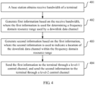
- Step 401 A base station obtains receive bandwidth of a terminal. Optionally, the base station also receives channel state information (CSI) of the terminal.
- CSI channel state information
- Step 402 The base station generates first information based on the receive bandwidth, where the first information is used for determining a frequency domain resource range used by a downlink data channel.
- the receive bandwidth includes at least one first resource element.
- a bandwidth size of each first resource allocation unit is corresponding to a subband within the receive bandwidth.
- the base station evenly divides the receive bandwidth into several subbands based on the size of the first resource allocation unit.
- the first resource element may be a first-type RBG.
- a size of the first-type RBG may be set to P 1 based on a predefined or semi-statically configured size of the first-type RBG.
- the base station may correlate a value of the size P 1 of the first-type RBG to receive bandwidth N RB UE of UE, and pre-define a correspondence between the value of the size P 1 of the first-type RBG and the receive bandwidth N RB UE of the UE.
- the following Table 2 shows a possible correspondence between the size of the first-type RBG and the receive bandwidth of the UE.
- Table 2 Correspondence between the size of the first-type RBG and the receive bandwidth of the UE Receive bandwidth of UE Size of a first-type RBG N RB DL P 1 ⁇ 16 2 17-64 4 65-128 8 129-256 16
- the UE After the UE accesses an LTE system, the UE reports a receive bandwidth capability of the UE to the base station, and the base station determines a value of P 1 based on a correspondence between the receive bandwidth capability of the UE and the size of the first-type RBG.
- the base station After obtaining the channel state information and the receive bandwidth of the terminal, the base station determines the size of the first resource allocation unit and a location of a frequency domain resource of the downlink data channel configured to the terminal, and determines the first information based on the size of the first resource allocation unit and the location of the frequency domain resource of the downlink data channel configured to the terminal.
- the first information includes first indication information, second indication information, and first configuration information.
- the first indication information is used to indicate a bitmap of the frequency domain resource range on the receive bandwidth.
- the bitmap includes at least one bit, and each of the at least one bit indicates one first resource element.
- the second information indicates the location of the downlink data channel within the frequency domain resource range.
- the first configuration information is used for configuring a size of a second resource element. After generating the first information, the base station adds the first information to DCI in the level-1 control channel.
- Step 403 The base station generates second information based on the first information, where the second information is used to indicate a location of the downlink data channel within the frequency domain resource range, and the base station adds the generated second information to DCI in the level-2 control channel.
- Step 404 The base station sends the first information to the terminal through the level-1 control channel, and sends the second information to the terminal through the level-2 control channel.
- the base station first sends the level-1 control channel that carries the first information to the terminal, then sends the level-2 control channel that carries the second information to the terminal, and also sends a downlink data resource to the terminal.
- step 402 that the base station determines the size of the first resource element based on the receive bandwidth includes:
- a process in which the base station generates the first information includes: The base station configures the first-type RBG based on information such as the received receive bandwidth of the terminal and the CSI.
- the base station divides operating receive bandwidth N RB UE of the UE into ⁇ N RB UE / P 1 ⁇ bandwidth regions based on the size of the first-type RBG.
- a size of each bandwidth region in frequency domain is P 1 RBs that are contiguous in frequency domain, where P 1 is the size of the first-type RBG.
- the base station indicates, in the DCI in the level-1 control channel and by using the first indication information, a location, on the receive bandwidth of the UE, of a bandwidth region set in which a PDSCH resource allocated to the UE is located.
- a bitmap totally includes ⁇ N RB UE / P 1 ⁇ bits. Each bit is corresponding to one first-type RBG, a most significant bit represents first-type RBG 0, and a least significant bit represents first-type RBG ⁇ N RB UE / P 1 ⁇ ⁇ 1 . If an RB in a first-type RBG is allocated as a PDSCH resource of UE, a corresponding bit in the bitmap is set to 1; otherwise, a corresponding bit in the bitmap is set to 0.
- the first information generated by the base station includes the second indication information.
- the second indication information may be information required by the first information for indicating a size of a time-frequency resource of the level-2 control channel, and specifically includes the following information bits: a quantity of OFDM symbols occupied by the level-2 control channel: 1 or 2 bits, for example, as shown in the following Table 3.
- Table 3 Table of a correspondence between OFDM symbol information and a quantity of OFDM symbols Bit value 00 01 10 11 Quantity of OFDM symbols 1 2 3 4
- the second indication information further includes a quantity of control channel elements (CCE) used by the level-2 control channel, for example, 2 bits.
- CCE control channel elements
- the level-2 control channel is mapped onto a downlink time-frequency resource based on a CCE structure.
- Each CCE includes a fixed quantity of REs, for example, including 36 REs, for example, as shown in Table 4.
- Table 4 Table of a correspondence between CCE information and a quantity of CCEs Bit value 00 01 10 11 Quantity of CCEs 1 2 4 8
- the first information includes the first configuration information.
- the first configuration information is used as a 2-bit information field in the level-1 control channel.
- the information field is used for configuring a size P 2 of a second-type RBG, for example, as shown in Table 5.
- Table 5 Table of a correspondence between the first configuration information and the size of the second-type RBG Bit value 00 01 10 11 P 2 1 2 4 8
- the base station flexibly configures a value of the size P 2 of the second-type RBG, that is, P 2 PRBs that are contiguous in frequency domain, based on a bandwidth size of the PDSCH resource scheduled to the UE.
- the size of the second-type RBG should be less than the size of the first-type RBG, that is, P 2 ⁇ P 1 .
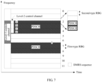
- one first-type RBG includes a plurality of second-type RBGs. As shown in FIG. 6 , one first-type RBG includes four second-type RBGs.
- the base station allocates, in the bandwidth region set in which the PDSCH resource is located, the PDSCH resource by using the second-type RBG as a resource allocation unit.
- the base station sends, to the terminal, the generated level-1 control channel, the generated level-2 control channel, and the location of the frequency domain resource of the downlink data channel configured to the terminal.
- the terminal receives and demodulates the level-1 control channel, and obtains the first information in the level-1 control channel, or obtains the first indication information, the second indication information, and the first configuration information in the DCI in the level-1 control channel. Then, the terminal performs blind detection on the level-2 control channel based on the obtained information.
- the UE obtains, based on the second indication information in the DCI in the level-1 control channel, sizes of resources occupied by the level-2 control channel in time domain and in frequency domain, and further obtains a DMRS sequence value used for demodulating the level-2 control channel.
- the UE determines, based on a location of a first bit that is set to 1 and that is in the bitmap in the DCI in the level-1 control channel, a bandwidth region in which a starting resource mapping position of the level-2 control channel is located, and obtains a value of a size of a resource allocation unit of the bandwidth region based on the first configuration information, that is, the value of the size P 2 of the second-type RBG.
- One bandwidth region includes ⁇ P 1 / P 2 ⁇ second-type RBGs, and the level-2 control channel may perform starting-position mapping on each of these second-type RBGs. Therefore, the UE demodulates the level-2 control channel at locations of the ⁇ P 1 / P 2 ⁇ second-type RBGs by using a DMRS sequence. That is, a maximum quantity of blind detection operations performed by the UE on the level-2 control channel is ⁇ P 1 / P 2 ⁇ .
- the size P 2 of the second-type RBG is set to 4, and a corresponding DMRS sequence used for demodulating the level-2 control channel is "abed".
- a horizontal coordinate represents time domain, and a longitudinal axis represents frequency domain.
- a first bit coded 1 in the bitmap is in a third bit in the bitmap.
- the bandwidth region in which the starting resource mapping position of the level-2 control channel is located is first-type RBG 2.
- This embodiment of this application provides the method for allocating a PDSCH resource through joint indication by using control channels of two levels.
- a downlink resource allocation unit that is, the size of the second-type RBG, can be configured based on a downlink resource scheduling status, thereby improving flexibility of PDSCH resource allocation; and bandwidth regions are obtained through division based on the level-1 control channel, and the level-2 control channel further indicates a resource allocation location within a bandwidth region set, thereby reducing indication information overheads in the level-1 control channel and also reducing information indication overheads used for resource allocation in the control channels.
- the bitmap information is equivalent to the resource allocation information.
- the 48 bits are overheads used by the level-1 control channel in the LTE system for the resource allocation information. In other words, the overheads are 48 bits.
- the bitmap information is resource allocation information in the level-1 control channel, that is, the generated first information.
- the first information includes the first indication information.
- the 12 bits are overheads used by the level-1 control channel for the resource allocation information. In other words, the overheads are 12 bits. If locations of frequency domain resources of a PDSCH are shown in the figure, the bitmap information in the DCI in the level-1 control channel is "001110111000".
- the configured size P 2 of the second-type RBG is set to 4. The UE obtains a value of P 2 from the 2-bit first configuration information.
- bitmap in the DCI in the level-1 control channel is "001110111000"
- L 6 bits coded "1"
- the frequency domain resources of the PDSCH are in bandwidth regions of first-type RBGs 2, 3, 4, 6, 7, and 8.
- Bitmap information is resource allocation information in the level-2 control channel, that is, third indication information.
- the 24 bits are overheads used by the level-2 control channel for the resource allocation information.
- required channel overheads are: the overheads of the level-1 control channel (that is, the first indication information): 12 bits; overheads of the first configuration information: 2 bits; and overheads of the third indication information: 24 bits. Total overheads of the three are 38 bits.
- the total overheads occupying the control channels are 38 bits, and are less than 48 bits used when only the level-1 control channel is used to indicate PDSCH resource allocation information, thereby effectively reducing information indication overheads used by the control channel for resource allocation.
- this embodiment further provides a resource receiving method, applied to a terminal device.
- the method includes the following steps.
- Step 801 A terminal receives a level-1 control channel and a level-2 control channel that are sent by a base station.
- Step 802 The terminal demodulates the level-1 control channel, to obtain first information, where the first information is used for determining a frequency domain resource range used by a downlink data channel, and the first information includes first indication information, second indication information, and first configuration information.
- Step 803 The terminal demodulates the level-2 control channel based on the first information, to obtain second information from the level-2 control channel, where the second information is used to indicate a location of a downlink data resource within the frequency domain resource range.
- Step 804 The terminal determines a location of the downlink data resource in frequency domain based on the second information and the first information.
- the first information includes the second indication information
- that the terminal demodulates the level-2 control channel based on the first information, to obtain second information includes: obtaining, by the terminal based on the second indication information, sizes of resources occupied by the level-2 control channel in time domain and frequency domain; and demodulating the level-2 control channel based on the second indication information, and generating the second information, where the second information includes third indication information, and the third indication information is used to indicate a bitmap of the downlink data channel within the frequency domain resource range.
- the terminal after receiving and demodulating the level-2 control channel, the terminal, for example, UE, obtains the third indication information in the second information in the level-2 control channel, and obtains PDSCH resource allocation information based on the first indication information and the first configuration information in the first information.
- the UE determines, based on a location of a bit that is coded "1" and that is in a bitmap in DCI in the level-1 control channel, a location of a bandwidth region set, on receive bandwidth of the UE, in which a PDSCH resource is located.
- Each bandwidth region has ⁇ P 1 / P 2 ⁇ second-type RBGs. If the bitmap in the DCI in the level-1 control channel totally has L bits coded "1", the bandwidth region set totally has ⁇ LP 1 / P 2 ⁇ second-type RBGs. In this case, a bitmap in DCI in the level-2 control channel totally includes ⁇ LP 1 / P 2 ⁇ bits.
- Each bit is corresponding to one second-type RBG, a most significant bit represents second-type RBG 0, and a least significant bit represents RBG ⁇ LP 1 / P 2 ⁇ ⁇ 1 . If a second-type RBG in the bandwidth region set is allocated as a PDSCH resource of UE, a corresponding bit in the bitmap in the DCI in the level-2 control channel is set to 1; otherwise, a corresponding bit in the bitmap in the DCI in the level-2 control channel is set to 0.
- the UE determines a location of the PDSCH resource in frequency domain based on the location of the bandwidth region set, on the receive bandwidth of the UE, in which the PDSCH resource is located, and based on a location of the PDSCH resource in the bandwidth region set.
- bitmap in the DCI (that is, the first indication information) in the level-1 control channel is "001110111000”
- L 6 bits coded "1"
- each first-type RBG represents one bandwidth region
- first-type RBGs 2, 3, 4, 6, 7, and 8 form the bandwidth region set.
- PDSCH resources allocated to the UE are second-type RBGs 2-11 and 15-23.
- the second information further includes second configuration information, and the second configuration information is used to indicate a manner in which a downlink data channel resource scheduled by the base station to the terminal next time is allocated.
- the terminal obtains, based on an indication of the information field, a manner in which a PDSCH resource scheduled by the base station to the UE next time is allocated.
- a PDSCH resource is allocated to the UE through the level-1 control channel.
- resource allocation methods of resource allocation type 0, type 1, and type 2 in an LTE system may be used in the level-1 control channel.
- a PDSCH resource is allocated to the UE through joint indication by using control channels of two levels.
- Resource allocation methods are method procedures of step 401 to step 404 and step 801 to step 804 in the foregoing embodiments.
- the base station may alternatively set the value of the information bit based on a status of next PDSCH resource scheduling.
- a current PDSCH resource allocation manner may be predefined or may be set by using a higher layer signaling indication.
- a resource configuration method is further provided.
- locations of downlink data channels within a shared frequency domain resource range are indicated for a group of terminals by using a level-1 control channel.
- the method includes the following steps.
- Step 901 A base station obtains receive bandwidth reported by a plurality of terminals.
- the base station obtains channel state information CSI and receive bandwidth information of the terminals, and determines a first resource allocation unit, that is, a size of a first-type RBG, based on the receive bandwidth.
- the base station determines, based on the CSI of the terminal UEs, sizes and frequency-domain locations of PDSCH resources scheduled to the terminals.
- Step 902 The base station groups the plurality of terminals based on the receive bandwidth, and configures a same level-1 control channel for terminals in a same group.
- the base station groups the different accessed UEs based on the receive bandwidth of the UEs and a PDSCH resource scheduling status.
- the base station classifies these UEs into a group.
- the base station configures a same level-1 control channel for the UEs in the group, as shown in FIG. 10 , and divides the receive bandwidth into bandwidth regions for the UEs in the group based on the same size of the first-type RBG.
- the size of the first-type RBG may be determined by using the method described in step 401 to step 404 in the foregoing embodiment.
- Step 903 The base station generates, based on channel state information and receive bandwidth information, first information that is used for determining a frequency domain resource range used by downlink data channels.
- Second information is generated based on the channel information, locations of frequency domain resources of downlink data channels configured to the terminals, and the first information.
- the second information is mainly used to indicate a location of a frequency domain resource occupied by a downlink data resource within the first range.
- a difference between this step and the foregoing embodiment is that a bitmap in DCI in the level-1 control channel is used to indicate a location, on the UE receive bandwidth, of a bandwidth region set in which PDSCH resources of all the UEs in the group are located.
- Step 904 The base station generates second information based on the first information and the channel state information, where the second information is used to indicate a location of a downlink data resource within the frequency domain resource range.
- Step 905 The base station sends the unique level-1 control channel to the terminals in the group.
- Step 906 The base station sends, to each terminal in the same group, a level-2 control channel and a PDSCH resource corresponding to each terminal, where the level-1 control channel includes the first information, and the level-2 control channel includes the second information.
- Step 907 After receiving downlink channels of the same group, including the level-1 control channel, the level-2 control channels, and the PDSCH resources, the terminals demodulate the level-1 control channel, to obtain the second information from the level-1 control channel, where the second information includes first indication information, second indication information, and first configuration information.
- the terminals After receiving downlink channels of the same group, including the level-1 control channel, the level-2 control channels, and the PDSCH resources, the terminals demodulate the level-1 control channel, to obtain the second information from the level-1 control channel, where the second information includes first indication information, second indication information, and first configuration information.
- Each terminal in the group performs, based on the second information, blind detection on the level-2 control channel that belongs to the terminal.
- the UEs classified into the same group After receiving and demodulating the level-1 control channel, the UEs classified into the same group obtain bitmap information in the DCI.
- the bitmap indicates the bandwidth region set in which the PDSCH resources of all the UEs in the group are located. Therefore, in a bandwidth region corresponding to each bit set to "1" in the bitmap, there may be a starting resource location of a level-2 control channel of UE in the group. In this case, each UE in the group may need to perform blind detection on a level-2 control channel in the bandwidth region corresponding to each bit set to "1" in the bitmap.
- a blind detection method is the same as that described in step 801 to step 804 in the foregoing embodiment.
- Step 908 Each terminal demodulates the level-2 control channel based on the first information, to obtain third indication information from the level-2 control channel.
- Each terminal determines a location of a downlink data channel resource in frequency domain based on the third indication information, the first indication information, and the first configuration information.
- Step 909 Each terminal obtains allocation information about the PDSCH frequency domain resource based on the third indication information, the first indication information, and the first configuration information.
- the foregoing method further includes step 910: Further obtain second configuration information by performing blind detection on the second information.
- the second configuration information is used for determining a manner in which a PDSCH frequency domain resource scheduled by the base station to the terminal next time is allocated.
- the base station groups the plurality of terminals, and further when configuring a resource location in frequency domain for each terminal, uses the same level-1 control channel to indicate, simultaneously for a group of terminals, for example, for a plurality of UEs, the location of the bandwidth region set in which the PDSCH resource is located, thereby preventing the base station from generating the first information in the level-1 control channel for each terminal, and further reducing overheads of the level-1 control channel.
- the method provided in this aspect has the following improvement: PDSCH resource allocation information is no longer terminal-UE-specific, and some of resource allocation information may simultaneously indicate frequency domain location regions in which PDSCHs of a plurality of terminals are located. Therefore, overheads of resource allocation information are further reduced.
- This application further provides a base station, as shown in FIG. 11 , applied to a two-level control channel structure that includes a level-1 control channel and a level-2 control channel.
- the base station includes a transceiver 1101 and a processor 1102.
- the transceiver 1101 includes at least one communications interface and/or an I/O interface.
- the base station further includes a communications bus 1103 and a memory 1104.
- the transceiver 1101 is configured to obtain receive bandwidth of a terminal.
- the processor 1102 is configured to generate first information based on the receive bandwidth, where the first information is used for determining a frequency domain resource range used by a downlink data channel.
- the processor 1102 is further configured to generate second information based on the first information, where the second information is used to indicate a location of the downlink data channel within the frequency domain resource range.
- the transceiver 1101 is further configured to: send the first information to the terminal through the level-1 control channel, and send the second information to the terminal through the level-2 control channel.
- the receive bandwidth includes at least one first resource element; and the processor 1102 is further specifically configured to: determine a size of the first resource element based on the receive bandwidth; determine, based on the size of the first resource element, a location of the first resource element occupied within the frequency domain resource range; and generate the first information based on the location of the first resource element and the size of the first resource element.
- the processor 1102 is further configured to determine the size of the first resource element based on a predefined correspondence between the receive bandwidth and the size of the first resource element; and is further configured to: configure the size of the first resource element in a dynamic or semi-static manner by using radio resource control higher layer signaling.
- each of the at least one first resource element includes a plurality of second resource elements, and the first information further includes first configuration information used for configuring a size of the second resource element.
- the processor 1102 is further specifically configured to: determine, based on the size of the second resource element, a location of the downlink data channel in the second resource element occupied within the frequency domain resource range.
- the second information includes third indication information.
- the third indication information is used to indicate a bitmap of the downlink data channel within the frequency domain resource range.
- the bitmap includes at least one bit, and each of the at least one bit indicates one second resource element. That the first information is used for determining a frequency domain resource range used by a downlink data channel includes: the first information includes first indication information, where the first indication information is used to indicate a bitmap of the frequency domain resource range on the receive bandwidth; and the bitmap includes at least one bit, and each of the at least one bit indicates one first resource element.
- the first information further includes second indication information.
- the second indication information is used to indicate configuration information of the level-2 control channel.
- the second indication information includes a quantity of OFDM symbols occupied by the level-2 control channel and a quantity of control channel elements used by the level-2 control channel.
- the second information further includes second configuration information, and the second configuration information is used to indicate a manner in which a downlink data channel resource scheduled by the base station to the terminal next time is allocated.
- the transceiver 1101 and the processor 1102 of the base station in this embodiment may alternatively be a transceiver unit and a processing unit, respectively.
- the transceiver unit and the processing unit are configured to perform all functions of the transceiver 1101 and the processor 1102 in this embodiment, respectively.
- the terminal includes a transceiver 1201 and a processor 1202.
- the transceiver 1201 includes at least one communications interface and/or an I/O interface.
- the terminal further includes a communications bus 1203 and a memory 1204.
- the transceiver 1201 is configured to receive a level-1 control channel and a level-2 control channel that are sent by a base station.
- the processor 1202 is configured to demodulate the level-1 control channel, to obtain first information, where the first information is used for determining a frequency domain resource range used by a downlink data channel.
- the processor 1202 is further configured to demodulate the level-2 control channel based on the first information, to obtain second information from the level-2 control channel, where the second information is used to indicate a location of a downlink data resource within the frequency domain resource range.
- the processor 1202 is further configured to determine a location of the downlink data resource in frequency domain based on the second information and the first information.
- the first information includes second indication information
- the processor 1202 is further specifically configured to: obtain, based on the second indication information, sizes of resources occupied by the level-2 control channel in time domain and frequency domain; and demodulate the level-2 control channel based on the second indication information, and generate the second information, where the second information includes third indication information, and the third indication information is used to indicate a bitmap of the downlink data channel within the frequency domain resource range.
- the processor 1202 is further configured to determine, based on the second configuration information, a manner in which a downlink data channel resource scheduled by the base station to the processor 1202 next time is allocated.
- the transceiver 1201 and the processor 1202 of the terminal in this embodiment may alternatively be a transceiver unit and a processing unit, respectively.
- the transceiver unit and the processing unit are configured to perform all functions of the transceiver 1201 and the processor 1202 in this embodiment, respectively.
- This application further provides a resource configuration system.
- the system includes a base station and a terminal, and is applied to a two-level control channel structure that includes a level-1 control channel and a level-2 control channel.
- the base station is configured to: obtain receive bandwidth of the terminal; generate first information based on the receive bandwidth, where the first information is used for determining a frequency domain resource range used by a downlink data channel; generate second information based on the first information, where the second information is used to indicate a location of the downlink data channel within the frequency domain resource range; and send the first information to the terminal through the level-1 control channel, and send the second information to the terminal through the level-2 control channel.
- the terminal is configured to: receive a level-1 control channel and a level-2 control channel that are sent by the base station; demodulate the level-1 control channel, to obtain first information, where the first information is used for determining a frequency domain resource range used by a downlink data channel; demodulate the level-2 control channel based on the first information, to obtain second information from the level-2 control channel, where the second information is used to indicate a location of a downlink data resource within the frequency domain resource range; and determine a location of the downlink data resource in frequency domain based on the second information and the first information.
- the base station is further configured to: obtain receive bandwidth reported by a plurality of terminals; and group the plurality of terminals based on the receive bandwidth, and configure a same level-1 control channel for terminals in a same group; and the base station is further configured to generate first information and second information based on channel state information and receive bandwidth information, where the second information is used to indicate a location of a downlink data resource within a frequency domain resource range.
- the base station is further configured to send the level-1 control channel to the terminals in the group, and send a level-2 control channel to each terminal in the same group, so that after receiving and demodulating the level-1 control channel, each terminal obtains the first information, performs blind detection on the level-2 control channel based on the first information, and obtains a location of a PDSCH resource in frequency domain, thereby avoiding that the base station generates the first information in the level-1 control channel for each terminal, and further reducing overheads of the level-1 control channel.
- the processor may be a general-purpose central processing unit (CPU), a microprocessor, an application-specific integrated circuit (ASIC), or one or more integrated circuits configured to control program execution in the solutions of the present invention.
- CPU central processing unit
- ASIC application-specific integrated circuit
- the memory may be a read-only memory (ROM) or another type of static storage device capable of storing static information and instructions, or a random access memory (RAM) or another type of dynamic storage device capable of storing information and instructions; or may be an electrically erasable programmable read-only memory (EEPROM), a compact disc read-only memory (CD-ROM) or another compact disc storage, an optical disc storage (including a compressed optical disc, a laser disc, an optical disc, a digital universal optical disc, a blue-ray optical disc, and the like), a magnetic disk storage medium or another magnetic storage device, or any other medium capable of carrying or storing expected program code in a form of instructions or data structures and capable of being accessed by a computer, but is not limited thereto.
- the memory may independently exist, or may be integrated into the processor.
- the memory is configured to store application program code used to execute the solutions of the present invention, where the application program code is executed under control of the processor.
- the processor is configured to execute the application program code stored in the memory.
- the "unit” may be an application-specific integrated circuit (ASIC), a circuit, a processor that executes one or more software or firmware programs and a memory, an integrated logic circuit, and/or another device that can provide the foregoing functions.
- ASIC application-specific integrated circuit
- the embodiments of the present invention further provide a computer storage medium, configured to store a computer software instruction used by the resource configuration method and the resource receiving method shown in FIG. 4 , FIG. 8 , or FIG. 9 .
- the computer storage medium includes a program used to execute the foregoing method embodiments. After the stored program is executed, a feedback parameter can be sent.
- the embodiments of the present invention may be provided as a method, an apparatus (device), or a computer program product. Therefore, the present invention may use a form of hardware only embodiments, software only embodiments, or embodiments with a combination of software and hardware. Moreover, the present invention may use a form of a computer program product that is implemented on one or more computer-usable storage media (including but not limited to a disk memory, a CD-ROM, an optical memory, and the like) that include computer-usable program code.
- the computer program is stored/distributed in an appropriate medium, provided with other hardware or as a part of hardware, or may be distributed in another form such as in the Internet or in another wired or wireless telecommunications system.
- These computer program instructions may be provided for a general-purpose computer, a dedicated computer, an embedded processor, or a processor of any other programmable data processing device to generate a machine, so that the instructions executed by a computer or a processor of any other programmable data processing device generate an apparatus for implementing a specified function in one or more processes in the flowcharts and/or in one or more blocks in the block diagrams.
- These computer program instructions may alternatively be stored in a computer-readable memory that can instruct the computer or any other programmable data processing device to work in a specific manner, so that the instructions stored in the computer-readable memory generate an artifact that includes an instruction apparatus.
- the instruction apparatus implements a specified function in one or more processes in the flowcharts and/or in one or more blocks in the block diagrams.
- These computer program instructions may alternatively be loaded onto a computer or another programmable data processing device, so that a series of operations and steps are performed on the computer or the another programmable device, thereby generating computer-implemented processing. Therefore, the instructions executed on the computer or the another programmable device provide steps for implementing a specified function in one or more processes in the flowcharts and/or in one or more blocks in the block diagrams.
Landscapes
- Engineering & Computer Science (AREA)
- Signal Processing (AREA)
- Computer Networks & Wireless Communication (AREA)
- Mobile Radio Communication Systems (AREA)
Claims (8)
- Ressourcenkonfigurationsverfahren, das auf eine zweistufige Steuerkanalstruktur angewendet wird, die einen Steuerkanal der Stufe 1 und einen Steuerkanal der Stufe 2 umfasst, wobei das Verfahren Folgendes umfasst:Erhalten (401) der Empfangsbandbreite eines Terminals durch eine Basisstation;Erzeugen (402) erster Informationen durch die Basisstation basierend auf der Empfangsbandbreite, wobei die ersten Informationen zum Bestimmen eines von einem Downlink-Datenkanal verwendeten Frequenzbereichs-Ressourcenbereichs verwendet werden;Erzeugen (403) von zweiten Informationen durch die Basisstation auf der Grundlage der ersten Informationen, wobei die zweiten Informationen verwendet werden, um einen Ort des Downlink-Datenkanals innerhalb des Frequenzbereichs-Ressourcenbereichs anzuzeigen;Senden (404) der ersten Informationen durch die Basisstation an das Endgerät über den Steuerkanal der Ebene 1 und Senden der zweiten Informationen an das Endgerät über den Steuerkanal der Ebene 2,wobei die Empfangsbandbreite mindestens ein erstes Ressourcenelement umfasst; das Verfahren dadurch gekennzeichnet ist, dassdas Erzeugen erster Informationen auf Grundlage der Empfangsbandbreite Folgendes umfasst:Bestimmen einer Größe des ersten Ressourcenelements durch die Basisstation basierend auf der Empfangsbandbreite;Bestimmen, durch die Basisstation, basierend auf der Größe des ersten Ressourcenelements, eines Orts des ersten Ressourcenelements, das innerhalb des Frequenzbereichs der Ressourcen belegt ist; undGenerieren der ersten Informationen durch die Basisstation basierend auf dem Ort des ersten Ressourcenelements und der Größe des ersten Ressourcenelements.
- Basisstation, die auf eine zweistufige Steuerkanalstruktur angewendet wird, die einen Steuerkanal der Stufe 1 und einen Steuerkanal der Stufe 2 umfasst, wobei die Basisstation eine Sende-/Empfangseinheit (1101) und einen Prozessor (1102) umfasst;die Sende-/Empfangseinheit (1101) dazu konfiguriert ist, die Empfangsbandbreite eines Endgeräts zu erhalten;die Verarbeitungseinheit (1102) dazu konfiguriert ist, erste Informationen basierend auf der Empfangsbandbreite zu erzeugen, wobei die ersten Informationen zum Bestimmen eines von einem Downlink-Datenkanal verwendeten Frequenzbereichs-Ressourcenbereichs verwendet werden;die Verarbeitungseinheit (1102) ferner dazu konfiguriert ist, zweite Informationen basierend auf den ersten Informationen zu erzeugen, wobei die zweiten Informationen dazu verwendet werden, einen Ort des Downlink-Datenkanals innerhalb des Frequenzbereichs-Ressourcenbereichs anzugeben; unddie Sende-/Empfangseinheit (1101) ferner dazu konfiguriert ist, die ersten Informationen über den Level-1-Steuerkanal an das Endgerät zu senden und die zweiten Informationen über den Level-2-Steuerkanal an das Endgerät zu senden,wobei die Empfangsbandbreite mindestens ein erstes Ressourcenelement umfasst; die Basisstation dadurch gekennzeichnet ist, dassdie Verarbeitungseinheit ferner speziell konfiguriert ist zum: Bestimmen einer Größe des ersten Ressourcenelements basierend auf der Empfangsbandbreite; basierend auf der Größe des ersten Ressourcenelements, Bestimmen eines Ortes des ersten Ressourcenelements innerhalb des Frequenzbereichs-Ressourcenbereichs; und basierend auf dem Ort des ersten Ressourcenelements und der Größe des ersten Ressourcenelements, Erzeugen der ersten Informationen.
- Basisstation nach Anspruch 2, wobei die Verarbeitungseinheit ferner dazu konfiguriert ist, die Größe des ersten Ressourcenelements basierend auf einer vordefinierten Entsprechung zwischen der Empfangsbandbreite und der Größe des ersten Ressourcenelements zu bestimmen.
- Basisstation nach Anspruch 2, wobei
die Verarbeitungseinheit ferner konfiguriert ist zum: Konfigurieren der Größe des ersten Ressourcenelements durch Verwendung einer Radio Resource Control-Signalisierung auf höherer Ebene dynamisch oder halbstatisch. - Basisstation nach Anspruch 2, wobei jedes des mindestens einen ersten Ressourcenelements eine Vielzahl von zweiten Ressourcenelementen umfasst und die ersten Informationen ferner erste Konfigurationsinformationen umfassen, die zum Konfigurieren einer Größe des zweiten Ressourcenelements verwendet werden; und
die Verarbeitungseinheit ferner speziell dazu konfiguriert ist, basierend auf der Größe des zweiten Ressourcenelements einen Ort des Downlink-Datenkanals im zweiten Ressourcenelement zu bestimmen, der innerhalb des Frequenzbereichs-Ressourcenbereichs belegt ist. - Basisstation nach Anspruch 5, wobei die zweiten Informationen dritte Angabeinformationen umfassen; und
die dritte Angabeinformation wird verwendet, um eine Bitmap des Downlink-Datenkanals innerhalb des Frequenzbereichsressourcenbereichs anzuzeigen, wobei die Bitmap innerhalb des Frequenzbereichs-Ressourcenbereichs mindestens ein Bit umfasst und jedes der mindestens einen Bits zeigt ein zweites Ressourcenelement an. - Basisstation nach Anspruch 6, wobei die zweiten Angabeinformationen Folgendes umfassen:
eine Anzahl von OFDM-Symbolen, die vom Level-2-Steuerkanal belegt werden, und eine Anzahl von Steuerkanalelementen, die vom Level-2-Steuerkanal verwendet werden. - Basisstation nach einem der Ansprüche 2 bis 7, wobei die zweiten Informationen ferner zweite Konfigurationsinformationen umfassen und die zweiten Konfigurationsinformationen verwendet werden, um eine Art und Weise anzugeben, in der eine von der Basisstation geplante Downlink-Datenkanalressource dem Endgerät beim nächsten Mal zugeteilt wird.
Applications Claiming Priority (2)
| Application Number | Priority Date | Filing Date | Title |
|---|---|---|---|
| CN201610872083.2A CN107889233B (zh) | 2016-09-29 | 2016-09-29 | 一种资源配置的方法及装置 |
| PCT/CN2017/103391 WO2018059391A1 (zh) | 2016-09-29 | 2017-09-26 | 一种资源配置的方法及装置 |
Publications (3)
| Publication Number | Publication Date |
|---|---|
| EP3512280A1 EP3512280A1 (de) | 2019-07-17 |
| EP3512280A4 EP3512280A4 (de) | 2019-09-04 |
| EP3512280B1 true EP3512280B1 (de) | 2024-09-25 |
Family
ID=61763131
Family Applications (1)
| Application Number | Title | Priority Date | Filing Date |
|---|---|---|---|
| EP17854841.8A Active EP3512280B1 (de) | 2016-09-29 | 2017-09-26 | Verfahren und vorrichtung für ressourcenzuweisung |
Country Status (4)
| Country | Link |
|---|---|
| US (1) | US11044147B2 (de) |
| EP (1) | EP3512280B1 (de) |
| CN (2) | CN107889233B (de) |
| WO (1) | WO2018059391A1 (de) |
Families Citing this family (13)
| Publication number | Priority date | Publication date | Assignee | Title |
|---|---|---|---|---|
| WO2019051695A1 (zh) * | 2017-09-13 | 2019-03-21 | Oppo广东移动通信有限公司 | 一种资源指示方法、设备和计算机存储介质 |
| JP7305625B2 (ja) * | 2018-05-11 | 2023-07-10 | 株式会社Nttドコモ | 端末、無線通信方法、基地局及びシステム |
| WO2020061950A1 (zh) * | 2018-09-27 | 2020-04-02 | Oppo广东移动通信有限公司 | 通信方法、终端设备和网络设备 |
| CN115175356B (zh) * | 2018-12-29 | 2025-06-13 | 华为技术有限公司 | 用于确定控制资源集合的频域位置的方法及相关设备 |
| US10986566B2 (en) * | 2019-01-28 | 2021-04-20 | Verizon Patent And Licensing Inc. | Systems and methods for bandwidth part selection initiated by a user equipment |
| CN112566246B (zh) * | 2019-09-10 | 2024-02-27 | 中磊电子股份有限公司 | 主控基站及资源分配指示方法 |
| US11523377B2 (en) * | 2020-02-14 | 2022-12-06 | T-Mobile Usa, Inc. | LTE resource allocation controller |
| CN111615201B (zh) * | 2020-04-15 | 2024-02-06 | 北京云智软通信息技术有限公司 | Coreset资源分配和指示方法及设备 |
| US11800552B1 (en) * | 2020-06-05 | 2023-10-24 | Space Exploration Technologies Corp. | System and method of providing a medium access control scheduler |
| CN114765862B (zh) * | 2021-01-12 | 2025-03-14 | 大唐移动通信设备有限公司 | 波束指示方法、装置及处理器可读存储介质 |
| US20240073961A1 (en) * | 2021-01-12 | 2024-02-29 | Beijing Xiaomi Mobile Software Co., Ltd. | Access resource determination method, access resource determination apparatus and storage medium |
| CN117242724B (zh) * | 2022-04-12 | 2025-04-29 | 北京小米移动软件有限公司 | 信息传输方法、装置、通信设备和存储介质 |
| WO2023197264A1 (zh) * | 2022-04-14 | 2023-10-19 | 北京小米移动软件有限公司 | 资源配置的方法、装置、通信设备及存储介质 |
Family Cites Families (15)
| Publication number | Priority date | Publication date | Assignee | Title |
|---|---|---|---|---|
| GB2464987A (en) | 2008-11-03 | 2010-05-05 | Nec Corp | Methods for designating resource allocation |
| US8467799B2 (en) * | 2009-08-20 | 2013-06-18 | Samsung Electronics Co., Ltd. | Method and system for assigning physical uplink control channel (PUCCH) resources |
| CN102724757B (zh) * | 2011-03-30 | 2017-11-07 | 中兴通讯股份有限公司 | 一种控制信道信息处理方法和系统 |
| CN102448175B (zh) * | 2012-01-18 | 2015-08-12 | 中兴通讯股份有限公司 | 一种长期演进系统中分配资源块组的方法及装置 |
| CN103220796B (zh) * | 2012-01-21 | 2016-09-21 | 电信科学技术研究院 | 一种下行数据传输方法及其设备 |
| CN103369675B (zh) * | 2012-04-06 | 2016-01-27 | 华为技术有限公司 | 一种资源配置方法和装置 |
| US20170251465A1 (en) * | 2015-03-09 | 2017-08-31 | Telefonaktiebolaget Lm Ericsson (Publ) | Reducing reference signals when communicating multiple sub-subframes between a base station and a wireless terminal |
| WO2017018761A1 (ko) * | 2015-07-24 | 2017-02-02 | 엘지전자 주식회사 | 제어 정보 수신 방법 및 사용자기기와, 제어 정보 수신 방법 및 기지국 |
| HUE053508T2 (hu) * | 2015-11-03 | 2021-07-28 | Ericsson Telefon Ab L M | Eljárások és berendezés ütemezéshez felfelé irányuló kapcsolatban |
| US10397946B2 (en) * | 2015-12-17 | 2019-08-27 | Lg Electronics Inc. | Uplink reference signal transmitting or receiving method in wireless communication system, and apparatus therefor |
| US10594465B2 (en) * | 2016-02-22 | 2020-03-17 | Huawei Technologies Co., Ltd. | System and method for flexible channelization |
| KR101959123B1 (ko) * | 2016-05-12 | 2019-07-04 | 아서스테크 컴퓨터 인코포레이션 | 무선 통신 시스템에서의 서로 다른 전송 시간 간격들을 통한 제어 채널들의 원활한 탐지 |
| EP3456126B1 (de) * | 2016-05-13 | 2022-03-02 | Telefonaktiebolaget LM Ericsson (publ) | Konfiguration von uplink-übertragungen für eine drahtlose vorrichtung |
| WO2017194707A1 (en) * | 2016-05-13 | 2017-11-16 | Telefonaktiebolaget Lm Ericsson (Publ) | Allocation of resources to a wireless device |
| US20190181991A1 (en) * | 2016-05-13 | 2019-06-13 | Telefonaktiebolaget Lm Ericsson (Publ) | Granting Resources To A Wireless Device |
-
2016
- 2016-09-29 CN CN201610872083.2A patent/CN107889233B/zh active Active
- 2016-09-29 CN CN202010399355.8A patent/CN111885716A/zh not_active Withdrawn
-
2017
- 2017-09-26 WO PCT/CN2017/103391 patent/WO2018059391A1/zh not_active Ceased
- 2017-09-26 EP EP17854841.8A patent/EP3512280B1/de active Active
-
2019
- 2019-03-28 US US16/367,510 patent/US11044147B2/en active Active
Also Published As
| Publication number | Publication date |
|---|---|
| CN107889233A (zh) | 2018-04-06 |
| US11044147B2 (en) | 2021-06-22 |
| CN107889233B (zh) | 2020-05-08 |
| EP3512280A4 (de) | 2019-09-04 |
| EP3512280A1 (de) | 2019-07-17 |
| US20190229986A1 (en) | 2019-07-25 |
| WO2018059391A1 (zh) | 2018-04-05 |
| CN111885716A (zh) | 2020-11-03 |
Similar Documents
| Publication | Publication Date | Title |
|---|---|---|
| US11044147B2 (en) | Resource configuration method and apparatus | |
| EP3595364B1 (de) | Ressourcenzuweisungsverfahren, netzwerkvorrichtung und endgerätevorrichtung | |
| EP3661294B1 (de) | Verfahren, vorrichtung und system zur anpassung einer frequenzdomänenressource und zum senden von anzeigeinformationen | |
| EP3334228B1 (de) | Ressourcenzuweisungsverfahren und -vorrichtung | |
| US20180192409A1 (en) | Frequency spectrum resource allocation method and apparatus | |
| CN106413105B (zh) | 一种资源传输的指示方法、装置、网络侧设备及终端 | |
| EP3606236B1 (de) | Verfahren und vorrichtung zur bestimmung einer transportblockgrösse | |
| US11765741B2 (en) | Radio communication method, chip, and system | |
| EP4468802A1 (de) | Datenübertragungsverfahren und -vorrichtung sowie speichermedium, endgerät und netzwerkvorrichtung | |
| CN110089171B (zh) | 传输信息的方法、网络设备和终端设备 | |
| EP3565166B1 (de) | Verfahren zum senden und empfangen von downlink-steuerinformationen und vorrichtung | |
| US20140307692A1 (en) | Transmitter, method and terminal for allocating resources, and method of receiving resource allocation information | |
| US20220376847A1 (en) | Methods and apparatus for multiple component carrier physical downlink shared channel scheduling in wireless communication | |
| CN113647163B (zh) | 一种通信方法及设备 | |
| EP3941132A1 (de) | Verfahren und vorrichtung zur blinddetektion | |
| EP4593493A1 (de) | Uplink-übertragungsverfahren und kommunikationsvorrichtung | |
| EP2870811B1 (de) | Verfahren und netzwerkknoten zur zuweisung von ressourcen eines uplink-subframes | |
| US11196529B2 (en) | Indication method, processing method, and apparatus | |
| CN110547011B (zh) | 无线通信的方法、终端设备和网络设备 | |
| US11546123B2 (en) | Wireless communication method and device | |
| US20180270034A1 (en) | Data Transmission Method, And Apparatus | |
| EP3573395B1 (de) | Kommunikationsverfahren und -vorrichtung | |
| US20250105960A1 (en) | Method for determining transport block size, and device | |
| US12395303B2 (en) | Resource configuration method and apparatus | |
| US20190261334A1 (en) | Transmission control method, apparatus, and system, and storage medium |
Legal Events
| Date | Code | Title | Description |
|---|---|---|---|
| STAA | Information on the status of an ep patent application or granted ep patent |
Free format text: STATUS: THE INTERNATIONAL PUBLICATION HAS BEEN MADE |
|
| PUAI | Public reference made under article 153(3) epc to a published international application that has entered the european phase |
Free format text: ORIGINAL CODE: 0009012 |
|
| STAA | Information on the status of an ep patent application or granted ep patent |
Free format text: STATUS: REQUEST FOR EXAMINATION WAS MADE |
|
| 17P | Request for examination filed |
Effective date: 20190408 |
|
| AK | Designated contracting states |
Kind code of ref document: A1 Designated state(s): AL AT BE BG CH CY CZ DE DK EE ES FI FR GB GR HR HU IE IS IT LI LT LU LV MC MK MT NL NO PL PT RO RS SE SI SK SM TR |
|
| AX | Request for extension of the european patent |
Extension state: BA ME |
|
| REG | Reference to a national code |
Ref country code: DE Ref legal event code: R079 Free format text: PREVIOUS MAIN CLASS: H04W0072040000 Ipc: H04L0005000000 |
|
| A4 | Supplementary search report drawn up and despatched |
Effective date: 20190801 |
|
| RIC1 | Information provided on ipc code assigned before grant |
Ipc: H04L 5/00 20060101AFI20190726BHEP |
|
| DAV | Request for validation of the european patent (deleted) | ||
| DAX | Request for extension of the european patent (deleted) | ||
| STAA | Information on the status of an ep patent application or granted ep patent |
Free format text: STATUS: EXAMINATION IS IN PROGRESS |
|
| 17Q | First examination report despatched |
Effective date: 20210730 |
|
| RIC1 | Information provided on ipc code assigned before grant |
Ipc: H04W 72/04 20090101ALI20240417BHEP Ipc: H04L 5/00 20060101AFI20240417BHEP |
|
| GRAP | Despatch of communication of intention to grant a patent |
Free format text: ORIGINAL CODE: EPIDOSNIGR1 |
|
| STAA | Information on the status of an ep patent application or granted ep patent |
Free format text: STATUS: GRANT OF PATENT IS INTENDED |
|
| INTG | Intention to grant announced |
Effective date: 20240529 |
|
| GRAS | Grant fee paid |
Free format text: ORIGINAL CODE: EPIDOSNIGR3 |
|
| GRAA | (expected) grant |
Free format text: ORIGINAL CODE: 0009210 |
|
| STAA | Information on the status of an ep patent application or granted ep patent |
Free format text: STATUS: THE PATENT HAS BEEN GRANTED |
|
| AK | Designated contracting states |
Kind code of ref document: B1 Designated state(s): AL AT BE BG CH CY CZ DE DK EE ES FI FR GB GR HR HU IE IS IT LI LT LU LV MC MK MT NL NO PL PT RO RS SE SI SK SM TR |
|
| REG | Reference to a national code |
Ref country code: GB Ref legal event code: FG4D |
|
| REG | Reference to a national code |
Ref country code: CH Ref legal event code: EP |
|
| P01 | Opt-out of the competence of the unified patent court (upc) registered |
Free format text: CASE NUMBER: APP_48755/2024 Effective date: 20240827 |
|
| REG | Reference to a national code |
Ref country code: DE Ref legal event code: R096 Ref document number: 602017085122 Country of ref document: DE |
|
| REG | Reference to a national code |
Ref country code: IE Ref legal event code: FG4D |
|
| REG | Reference to a national code |
Ref country code: LT Ref legal event code: MG9D |
|
| PG25 | Lapsed in a contracting state [announced via postgrant information from national office to epo] |
Ref country code: NO Free format text: LAPSE BECAUSE OF FAILURE TO SUBMIT A TRANSLATION OF THE DESCRIPTION OR TO PAY THE FEE WITHIN THE PRESCRIBED TIME-LIMIT Effective date: 20241225 |
|
| PG25 | Lapsed in a contracting state [announced via postgrant information from national office to epo] |
Ref country code: GR Free format text: LAPSE BECAUSE OF FAILURE TO SUBMIT A TRANSLATION OF THE DESCRIPTION OR TO PAY THE FEE WITHIN THE PRESCRIBED TIME-LIMIT Effective date: 20241226 Ref country code: FI Free format text: LAPSE BECAUSE OF FAILURE TO SUBMIT A TRANSLATION OF THE DESCRIPTION OR TO PAY THE FEE WITHIN THE PRESCRIBED TIME-LIMIT Effective date: 20240925 |
|
| PG25 | Lapsed in a contracting state [announced via postgrant information from national office to epo] |
Ref country code: BG Free format text: LAPSE BECAUSE OF FAILURE TO SUBMIT A TRANSLATION OF THE DESCRIPTION OR TO PAY THE FEE WITHIN THE PRESCRIBED TIME-LIMIT Effective date: 20240925 |
|
| PG25 | Lapsed in a contracting state [announced via postgrant information from national office to epo] |
Ref country code: LV Free format text: LAPSE BECAUSE OF FAILURE TO SUBMIT A TRANSLATION OF THE DESCRIPTION OR TO PAY THE FEE WITHIN THE PRESCRIBED TIME-LIMIT Effective date: 20240925 |
|
| PG25 | Lapsed in a contracting state [announced via postgrant information from national office to epo] |
Ref country code: RS Free format text: LAPSE BECAUSE OF FAILURE TO SUBMIT A TRANSLATION OF THE DESCRIPTION OR TO PAY THE FEE WITHIN THE PRESCRIBED TIME-LIMIT Effective date: 20241225 |
|
| REG | Reference to a national code |
Ref country code: NL Ref legal event code: MP Effective date: 20240925 |
|
| PG25 | Lapsed in a contracting state [announced via postgrant information from national office to epo] |
Ref country code: RS Free format text: LAPSE BECAUSE OF FAILURE TO SUBMIT A TRANSLATION OF THE DESCRIPTION OR TO PAY THE FEE WITHIN THE PRESCRIBED TIME-LIMIT Effective date: 20241225 Ref country code: NO Free format text: LAPSE BECAUSE OF FAILURE TO SUBMIT A TRANSLATION OF THE DESCRIPTION OR TO PAY THE FEE WITHIN THE PRESCRIBED TIME-LIMIT Effective date: 20241225 Ref country code: LV Free format text: LAPSE BECAUSE OF FAILURE TO SUBMIT A TRANSLATION OF THE DESCRIPTION OR TO PAY THE FEE WITHIN THE PRESCRIBED TIME-LIMIT Effective date: 20240925 Ref country code: GR Free format text: LAPSE BECAUSE OF FAILURE TO SUBMIT A TRANSLATION OF THE DESCRIPTION OR TO PAY THE FEE WITHIN THE PRESCRIBED TIME-LIMIT Effective date: 20241226 Ref country code: FI Free format text: LAPSE BECAUSE OF FAILURE TO SUBMIT A TRANSLATION OF THE DESCRIPTION OR TO PAY THE FEE WITHIN THE PRESCRIBED TIME-LIMIT Effective date: 20240925 Ref country code: BG Free format text: LAPSE BECAUSE OF FAILURE TO SUBMIT A TRANSLATION OF THE DESCRIPTION OR TO PAY THE FEE WITHIN THE PRESCRIBED TIME-LIMIT Effective date: 20240925 |
|
| REG | Reference to a national code |
Ref country code: AT Ref legal event code: MK05 Ref document number: 1727551 Country of ref document: AT Kind code of ref document: T Effective date: 20240925 |
|
| PG25 | Lapsed in a contracting state [announced via postgrant information from national office to epo] |
Ref country code: NL Free format text: LAPSE BECAUSE OF FAILURE TO SUBMIT A TRANSLATION OF THE DESCRIPTION OR TO PAY THE FEE WITHIN THE PRESCRIBED TIME-LIMIT Effective date: 20240925 |
|
| REG | Reference to a national code |
Ref country code: DE Ref legal event code: R119 Ref document number: 602017085122 Country of ref document: DE |
|
| PG25 | Lapsed in a contracting state [announced via postgrant information from national office to epo] |
Ref country code: IS Free format text: LAPSE BECAUSE OF FAILURE TO SUBMIT A TRANSLATION OF THE DESCRIPTION OR TO PAY THE FEE WITHIN THE PRESCRIBED TIME-LIMIT Effective date: 20250125 Ref country code: PT Free format text: LAPSE BECAUSE OF FAILURE TO SUBMIT A TRANSLATION OF THE DESCRIPTION OR TO PAY THE FEE WITHIN THE PRESCRIBED TIME-LIMIT Effective date: 20250127 |
|
| PG25 | Lapsed in a contracting state [announced via postgrant information from national office to epo] |
Ref country code: SM Free format text: LAPSE BECAUSE OF FAILURE TO SUBMIT A TRANSLATION OF THE DESCRIPTION OR TO PAY THE FEE WITHIN THE PRESCRIBED TIME-LIMIT Effective date: 20240925 Ref country code: RO Free format text: LAPSE BECAUSE OF FAILURE TO SUBMIT A TRANSLATION OF THE DESCRIPTION OR TO PAY THE FEE WITHIN THE PRESCRIBED TIME-LIMIT Effective date: 20240925 |
|
| PG25 | Lapsed in a contracting state [announced via postgrant information from national office to epo] |
Ref country code: ES Free format text: LAPSE BECAUSE OF FAILURE TO SUBMIT A TRANSLATION OF THE DESCRIPTION OR TO PAY THE FEE WITHIN THE PRESCRIBED TIME-LIMIT Effective date: 20240925 |
|
| PG25 | Lapsed in a contracting state [announced via postgrant information from national office to epo] |
Ref country code: EE Free format text: LAPSE BECAUSE OF FAILURE TO SUBMIT A TRANSLATION OF THE DESCRIPTION OR TO PAY THE FEE WITHIN THE PRESCRIBED TIME-LIMIT Effective date: 20240925 Ref country code: AT Free format text: LAPSE BECAUSE OF FAILURE TO SUBMIT A TRANSLATION OF THE DESCRIPTION OR TO PAY THE FEE WITHIN THE PRESCRIBED TIME-LIMIT Effective date: 20240925 |
|
| PG25 | Lapsed in a contracting state [announced via postgrant information from national office to epo] |
Ref country code: CZ Free format text: LAPSE BECAUSE OF FAILURE TO SUBMIT A TRANSLATION OF THE DESCRIPTION OR TO PAY THE FEE WITHIN THE PRESCRIBED TIME-LIMIT Effective date: 20240925 Ref country code: PL Free format text: LAPSE BECAUSE OF FAILURE TO SUBMIT A TRANSLATION OF THE DESCRIPTION OR TO PAY THE FEE WITHIN THE PRESCRIBED TIME-LIMIT Effective date: 20240925 |
|
| PG25 | Lapsed in a contracting state [announced via postgrant information from national office to epo] |
Ref country code: SK Free format text: LAPSE BECAUSE OF FAILURE TO SUBMIT A TRANSLATION OF THE DESCRIPTION OR TO PAY THE FEE WITHIN THE PRESCRIBED TIME-LIMIT Effective date: 20240925 Ref country code: IT Free format text: LAPSE BECAUSE OF FAILURE TO SUBMIT A TRANSLATION OF THE DESCRIPTION OR TO PAY THE FEE WITHIN THE PRESCRIBED TIME-LIMIT Effective date: 20240925 |
|
| REG | Reference to a national code |
Ref country code: CH Ref legal event code: PL |
|
| PG25 | Lapsed in a contracting state [announced via postgrant information from national office to epo] |
Ref country code: LU Free format text: LAPSE BECAUSE OF NON-PAYMENT OF DUE FEES Effective date: 20240926 |
|
| PG25 | Lapsed in a contracting state [announced via postgrant information from national office to epo] |
Ref country code: MC Free format text: LAPSE BECAUSE OF FAILURE TO SUBMIT A TRANSLATION OF THE DESCRIPTION OR TO PAY THE FEE WITHIN THE PRESCRIBED TIME-LIMIT Effective date: 20240925 |
|
| PG25 | Lapsed in a contracting state [announced via postgrant information from national office to epo] |
Ref country code: DE Free format text: LAPSE BECAUSE OF NON-PAYMENT OF DUE FEES Effective date: 20250401 |
|
| PG25 | Lapsed in a contracting state [announced via postgrant information from national office to epo] |
Ref country code: DK Free format text: LAPSE BECAUSE OF FAILURE TO SUBMIT A TRANSLATION OF THE DESCRIPTION OR TO PAY THE FEE WITHIN THE PRESCRIBED TIME-LIMIT Effective date: 20240925 |
|
| REG | Reference to a national code |
Ref country code: BE Ref legal event code: MM Effective date: 20240930 |
|
| PG25 | Lapsed in a contracting state [announced via postgrant information from national office to epo] |
Ref country code: BE Free format text: LAPSE BECAUSE OF NON-PAYMENT OF DUE FEES Effective date: 20240930 |
|
| PG25 | Lapsed in a contracting state [announced via postgrant information from national office to epo] |
Ref country code: CH Free format text: LAPSE BECAUSE OF NON-PAYMENT OF DUE FEES Effective date: 20240930 |
|
| PG25 | Lapsed in a contracting state [announced via postgrant information from national office to epo] |
Ref country code: IE Free format text: LAPSE BECAUSE OF NON-PAYMENT OF DUE FEES Effective date: 20240926 |
|
| PLBE | No opposition filed within time limit |
Free format text: ORIGINAL CODE: 0009261 |
|
| STAA | Information on the status of an ep patent application or granted ep patent |
Free format text: STATUS: NO OPPOSITION FILED WITHIN TIME LIMIT |
|
| 26N | No opposition filed |
Effective date: 20250626 |
|
| PG25 | Lapsed in a contracting state [announced via postgrant information from national office to epo] |
Ref country code: SE Free format text: LAPSE BECAUSE OF FAILURE TO SUBMIT A TRANSLATION OF THE DESCRIPTION OR TO PAY THE FEE WITHIN THE PRESCRIBED TIME-LIMIT Effective date: 20240925 |
|
| PGFP | Annual fee paid to national office [announced via postgrant information from national office to epo] |
Ref country code: GB Payment date: 20250807 Year of fee payment: 9 |
|
| PG25 | Lapsed in a contracting state [announced via postgrant information from national office to epo] |
Ref country code: FR Free format text: LAPSE BECAUSE OF NON-PAYMENT OF DUE FEES Effective date: 20241125 |
|
| PG25 | Lapsed in a contracting state [announced via postgrant information from national office to epo] |
Ref country code: HR Free format text: LAPSE BECAUSE OF FAILURE TO SUBMIT A TRANSLATION OF THE DESCRIPTION OR TO PAY THE FEE WITHIN THE PRESCRIBED TIME-LIMIT Effective date: 20240925 |
|
| PG25 | Lapsed in a contracting state [announced via postgrant information from national office to epo] |
Ref country code: CY Free format text: LAPSE BECAUSE OF FAILURE TO SUBMIT A TRANSLATION OF THE DESCRIPTION OR TO PAY THE FEE WITHIN THE PRESCRIBED TIME-LIMIT; INVALID AB INITIO Effective date: 20170926 |
|
| PG25 | Lapsed in a contracting state [announced via postgrant information from national office to epo] |
Ref country code: HU Free format text: LAPSE BECAUSE OF FAILURE TO SUBMIT A TRANSLATION OF THE DESCRIPTION OR TO PAY THE FEE WITHIN THE PRESCRIBED TIME-LIMIT; INVALID AB INITIO Effective date: 20170926 |