EP3514085A1 - Unité de transport et d'alimentation pour préformés - Google Patents
Unité de transport et d'alimentation pour préformés Download PDFInfo
- Publication number
- EP3514085A1 EP3514085A1 EP18152394.5A EP18152394A EP3514085A1 EP 3514085 A1 EP3514085 A1 EP 3514085A1 EP 18152394 A EP18152394 A EP 18152394A EP 3514085 A1 EP3514085 A1 EP 3514085A1
- Authority
- EP
- European Patent Office
- Prior art keywords
- conveyor belt
- preforms
- transport
- feed unit
- sensor
- Prior art date
- Legal status (The legal status is an assumption and is not a legal conclusion. Google has not performed a legal analysis and makes no representation as to the accuracy of the status listed.)
- Granted
Links
Images

Classifications
-
- B—PERFORMING OPERATIONS; TRANSPORTING
- B65—CONVEYING; PACKING; STORING; HANDLING THIN OR FILAMENTARY MATERIAL
- B65G—TRANSPORT OR STORAGE DEVICES, e.g. CONVEYORS FOR LOADING OR TIPPING, SHOP CONVEYOR SYSTEMS OR PNEUMATIC TUBE CONVEYORS
- B65G43/00—Control devices, e.g. for safety, warning or fault-correcting
- B65G43/08—Control devices operated by article or material being fed, conveyed or discharged
-
- B—PERFORMING OPERATIONS; TRANSPORTING
- B29—WORKING OF PLASTICS; WORKING OF SUBSTANCES IN A PLASTIC STATE IN GENERAL
- B29C—SHAPING OR JOINING OF PLASTICS; SHAPING OF MATERIAL IN A PLASTIC STATE, NOT OTHERWISE PROVIDED FOR; AFTER-TREATMENT OF THE SHAPED PRODUCTS, e.g. REPAIRING
- B29C31/00—Handling, e.g. feeding of the material to be shaped, storage of plastics material before moulding; Automation, i.e. automated handling lines in plastics processing plants, e.g. using manipulators or robots
- B29C31/008—Handling preformed parts, e.g. inserts
-
- B—PERFORMING OPERATIONS; TRANSPORTING
- B29—WORKING OF PLASTICS; WORKING OF SUBSTANCES IN A PLASTIC STATE IN GENERAL
- B29C—SHAPING OR JOINING OF PLASTICS; SHAPING OF MATERIAL IN A PLASTIC STATE, NOT OTHERWISE PROVIDED FOR; AFTER-TREATMENT OF THE SHAPED PRODUCTS, e.g. REPAIRING
- B29C49/00—Blow-moulding, i.e. blowing a preform or parison to a desired shape within a mould; Apparatus therefor
- B29C49/02—Combined blow-moulding and manufacture of the preform or the parison
- B29C49/06—Injection blow-moulding
-
- B—PERFORMING OPERATIONS; TRANSPORTING
- B29—WORKING OF PLASTICS; WORKING OF SUBSTANCES IN A PLASTIC STATE IN GENERAL
- B29C—SHAPING OR JOINING OF PLASTICS; SHAPING OF MATERIAL IN A PLASTIC STATE, NOT OTHERWISE PROVIDED FOR; AFTER-TREATMENT OF THE SHAPED PRODUCTS, e.g. REPAIRING
- B29C49/00—Blow-moulding, i.e. blowing a preform or parison to a desired shape within a mould; Apparatus therefor
- B29C49/42—Component parts, details or accessories; Auxiliary operations
- B29C49/4205—Handling means, e.g. transfer, loading or discharging means
- B29C49/42093—Transporting apparatus, e.g. slides, wheels or conveyors
- B29C49/42101—Conveyors, e.g. flat conveyor or clamping between two bands
-
- B—PERFORMING OPERATIONS; TRANSPORTING
- B65—CONVEYING; PACKING; STORING; HANDLING THIN OR FILAMENTARY MATERIAL
- B65G—TRANSPORT OR STORAGE DEVICES, e.g. CONVEYORS FOR LOADING OR TIPPING, SHOP CONVEYOR SYSTEMS OR PNEUMATIC TUBE CONVEYORS
- B65G47/00—Article or material-handling devices associated with conveyors; Methods employing such devices
- B65G47/34—Devices for discharging articles or materials from conveyor
- B65G47/46—Devices for discharging articles or materials from conveyor and distributing, e.g. automatically, to desired points
- B65G47/51—Devices for discharging articles or materials from conveyor and distributing, e.g. automatically, to desired points according to unprogrammed signals, e.g. influenced by supply situation at destination
- B65G47/5104—Devices for discharging articles or materials from conveyor and distributing, e.g. automatically, to desired points according to unprogrammed signals, e.g. influenced by supply situation at destination for articles
-
- B—PERFORMING OPERATIONS; TRANSPORTING
- B65—CONVEYING; PACKING; STORING; HANDLING THIN OR FILAMENTARY MATERIAL
- B65G—TRANSPORT OR STORAGE DEVICES, e.g. CONVEYORS FOR LOADING OR TIPPING, SHOP CONVEYOR SYSTEMS OR PNEUMATIC TUBE CONVEYORS
- B65G47/00—Article or material-handling devices associated with conveyors; Methods employing such devices
- B65G47/52—Devices for transferring articles or materials between conveyors i.e. discharging or feeding devices
- B65G47/68—Devices for transferring articles or materials between conveyors i.e. discharging or feeding devices adapted to receive articles arriving in one layer from one conveyor lane and to transfer them in individual layers to more than one conveyor lane or to one broader conveyor lane, or vice versa, e.g. combining the flows of articles conveyed by more than one conveyor
- B65G47/682—Devices for transferring articles or materials between conveyors i.e. discharging or feeding devices adapted to receive articles arriving in one layer from one conveyor lane and to transfer them in individual layers to more than one conveyor lane or to one broader conveyor lane, or vice versa, e.g. combining the flows of articles conveyed by more than one conveyor from a single conveyor lane consisting of one conveyor or several adjacent conveyors
-
- B—PERFORMING OPERATIONS; TRANSPORTING
- B29—WORKING OF PLASTICS; WORKING OF SUBSTANCES IN A PLASTIC STATE IN GENERAL
- B29C—SHAPING OR JOINING OF PLASTICS; SHAPING OF MATERIAL IN A PLASTIC STATE, NOT OTHERWISE PROVIDED FOR; AFTER-TREATMENT OF THE SHAPED PRODUCTS, e.g. REPAIRING
- B29C49/00—Blow-moulding, i.e. blowing a preform or parison to a desired shape within a mould; Apparatus therefor
- B29C49/02—Combined blow-moulding and manufacture of the preform or the parison
- B29C2049/023—Combined blow-moulding and manufacture of the preform or the parison using inherent heat of the preform, i.e. 1 step blow moulding
-
- B—PERFORMING OPERATIONS; TRANSPORTING
- B29—WORKING OF PLASTICS; WORKING OF SUBSTANCES IN A PLASTIC STATE IN GENERAL
- B29K—INDEXING SCHEME ASSOCIATED WITH SUBCLASSES B29B, B29C OR B29D, RELATING TO MOULDING MATERIALS OR TO MATERIALS FOR MOULDS, REINFORCEMENTS, FILLERS OR PREFORMED PARTS, e.g. INSERTS
- B29K2105/00—Condition, form or state of moulded material or of the material to be shaped
- B29K2105/25—Solid
- B29K2105/253—Preform
-
- B—PERFORMING OPERATIONS; TRANSPORTING
- B65—CONVEYING; PACKING; STORING; HANDLING THIN OR FILAMENTARY MATERIAL
- B65G—TRANSPORT OR STORAGE DEVICES, e.g. CONVEYORS FOR LOADING OR TIPPING, SHOP CONVEYOR SYSTEMS OR PNEUMATIC TUBE CONVEYORS
- B65G2201/00—Indexing codes relating to handling devices, e.g. conveyors, characterised by the type of product or load being conveyed or handled
- B65G2201/02—Articles
- B65G2201/0235—Containers
- B65G2201/0244—Bottles
-
- B—PERFORMING OPERATIONS; TRANSPORTING
- B65—CONVEYING; PACKING; STORING; HANDLING THIN OR FILAMENTARY MATERIAL
- B65G—TRANSPORT OR STORAGE DEVICES, e.g. CONVEYORS FOR LOADING OR TIPPING, SHOP CONVEYOR SYSTEMS OR PNEUMATIC TUBE CONVEYORS
- B65G2203/00—Indexing code relating to control or detection of the articles or the load carriers during conveying
- B65G2203/04—Detection means
- B65G2203/042—Sensors
- B65G2203/044—Optical
Definitions
- the invention relates to a transport and feed unit for preforms, in particular for PET bottles, wherein the transport and feed unit can be fed with preforms at its upstream end and feeds the preforms to a conveyor unit arranged at the downstream end of the transport and feed unit.
- U1 is a device for supplying preforms or preforms made of thermoplastic material with a support ring in the region of the open end to a blow molding machine for producing hollow bodies, with a ground-mounted silo for disorderly receiving multiple preforms, one of the preforms in one with the open end up-facing position-aligning and single-row forming sorters, a slant conveyor moving the preforms randomly from the silo to the roller sorter, and having a downwardly inclined slide supporting the support rings, which receives a plurality of open-ended upwardly facing preforms in a row and feeds them by means of downdraft of the blow molding machine, wherein the roller sorter is placed close to the ground and between the roller sorter and the elevated upper end of the chute, a preform raising elevator is turned on.
- the silo is periodically filled from above, by means of a corresponding tilting device by pouring supplied in boxes preforms.
- a disadvantage of this solution is that the preforms can be damaged or scratched by the bulk material or the impact in the silo and that in this case a very high noise level is generated.
- a device for feeding a conveyor system with a large amount of parts, such as preforms or hollow bodies comprises a tilting device with a pivotable tilting part and a device for intermediate storage of the parts, wherein the device for intermediate storage is a silo with a liftable cover and the tilting device has a mechanical connection and force transmission element which is connected to the liftable cover of the silo , Even with this solution, it may be due to the bulk material to damage / scratches on the preforms and to an increased noise level.
- a transport and feed unit for preforms in particular for PET bottles, specified, which is fed at its upstream end with preforms and the preforms of a arranged at the downstream end of the transport and feed unit conveyor unit feeding, wherein the transport and feed unit comprises a first conveyor belt and a second conveyor belt, wherein at the downstream end of the first conveyor belt a funnel-like device is provided, through which the preforms arrive on the second conveyor belt, which are the preforms of the arranged at its downstream end conveyor unit supplies.
- This solution is particularly suitable for high transport speeds (i.e., over 50,000 preforms per hour). However, it is relatively complex and costly.
- a transport and feed unit for preforms for preforms, in particular for PET bottles, wherein the transport and feed unit can be fed with preforms at its upstream end and supplies the preforms to a conveyor unit arranged at the downstream end of the transport and feed unit, wherein the transport and feed unit comprises a first conveyor belt and a second conveyor belt, the second conveyor belt being disposed at the downstream end of the first conveyor belt, the first conveyor belt feeding the preforms to the second conveyor belt, the second conveyor belt holding the preforms at its downstream end arranged feed unit supplies and wherein in the upstream end region (ie in the inlet) of the second conveyor belt, a distance sensor is arranged.
- the conveyor unit is presently not part of the claimed transport and feed unit.
- the first conveyor belt and the second conveyor belt are arranged at right angles to each other. On This way, a space-saving installation can be achieved.
- a bevel is arranged at the downstream end of the first conveyor belt, over which slide the preforms on the second conveyor belt.
- the slope is intended to ensure the smoothest possible transition of the preforms from the first to the second conveyor belt and for a good distribution of the preforms on the second conveyor belt.
- the slope also includes a dirt separation, preferably in the form of slots, so that dirt or impurities can not get onto the second conveyor belt.
- the slope extends at least over the entire width of the first conveyor belt and more preferably approximately to the middle of the second conveyor belt.
- a uniform distribution of the preforms on the second conveyor belt is achieved lengthwise and preferably one, optional and variable, narrowing or narrowing of the second conveyor belt.
- the distance sensor can be displaced laterally along the rear wall of the second conveyor belt.
- a first sensor (preferably in the form of a light barrier) is arranged in the upstream end region of the first conveyor belt. If the first sensor or the first light barrier no preforms detected more, the tilting device moves back to its original or loading position to receive a new box or a new batch of preforms.
- a second sensor (preferably in the form of a light barrier) is arranged between the first sensor and the downstream end region of the first conveyor belt. If the second sensor or the second light barrier does not detect any preforms, the tilting device regularly provided for feeding the first conveyor belt can again move into the pouring position and tilt a new batch of preforms onto the belt without the risk of backlogging or rolling back of Preforms is given.
- the first conveyor belt always moves at its normal transport speed.
- the tilting device is presently not part of the claimed transport and feed unit.
- a third sensor (preferably in the form of a light barrier) is arranged in the downstream end region of the first conveyor belt. If the third sensor detects no preforms in its area, the first conveyor belt is driven to drive faster to deliver preforms from behind.
- the (adjustable) distance sensor monitors when the second conveyor belt is free of preforms over the width of the first conveyor belt (possibly also approximately to the level of the downstream end of the slope). As long as this is not the case no further preforms are delivered to the second conveyor belt by the first conveyor belt. That is, when the third sensor detects preforms in its area and the distance sensor (still) preforms in the range of the width of the first conveyor belt (possibly also before the downstream end of the slope) detected on the second conveyor belt, the first conveyor belt is stopped.
- the first conveyor belt is restarted to deliver preforms. This is to prevent heaps or that subsequent preforms fall on the other preforms and scratch them and thereby additionally generate noise.
- the preform carpet on the first conveyor is thus controlled by the speed.
- the drive of the first conveyor belt insofar comprises a start-stop mechanism.
- a further sensor is arranged in the region of the downstream end of the slope. With this sensor, the speed of the second conveyor belt can be controlled. When the sensor is free (i.e., when it detects no preforms in its area), the speed of the second conveyor is increased, such as via a frequency converter.
- the other sensor should preferably be mounted near the transfer to the backpack silo, so that no preforms are "shot" into the backpack silo when switching to fast operation.
- the frequency converter setting may be selected to provide fast, slow, or consistent belt speed.
- the sensors are configured as light barriers. This form of sensors has proven to be particularly reliable and efficient for the underlying application. All sensors are otherwise connected to a conventional control.
- the first conveyor belt is fed via a tilting device arranged at its upstream end. This has proved to be advantageous in connection with the described speed control of the first conveyor belt.
- the second conveyor belt brings the preforms into a buffer device, preferably designed as a backpack silo, which is connected upstream of the conveyor unit.
- This buffer device ensures that the conveyor unit or the high-level conveyor can continue to supply preforms to downstream units if a correspondingly large gap arises on the second (and possibly also the first) conveyor belt.
- the backpack silo or the buffer device has a maximum level sensor with preforms. If the maximum level is reached, the second conveyor belt and possibly also the first conveyor belt is stopped.
- the backpack silo or the buffer device can additionally also have a minimum sensor. When the minimum level is reached, the second and possibly also the first conveyor belt is driven at a higher speed.
- the first conveyor belt is designed as a soft belt. In this way, damage and / or scratches of the preforms are avoided when pouring onto the first conveyor belt and it can be additionally reduced noise.
- the second (transverse) conveyor belt can be designed as a soft band accordingly.
- the first conveyor belt has a length between 2000 mm and 3000 mm, preferably between 2250 mm and 2750 mm. Further preferably, the first conveyor belt has a width of 1500 mm to 3500 mm, preferably from 2000 mm to 3000 mm.
- the second conveyor belt has a length between 2000 mm and 5000 mm, preferably between 2500 mm and 4000 mm. Further preferably, the second conveyor belt has a width of 200 mm to 1000 mm, preferably from 200 to 500 mm.
- first conveyor belt By using the sensors described above or the corresponding control / regulating mechanism, in particular a relatively short first conveyor belt can be used. Above all, it is not necessary to provide an additional (longitudinal) conveyor belt adjoining the first conveyor belt in order to sufficiently pull apart the quantity of preforms in front of the second (transverse) conveyor belt with a view to continuous operation as far as possible.
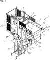
- Fig. 1 an arrangement consisting of an inventive transport and feed unit 1 with upstream tilting device 2 and downstream high conveyor 7 is illustrated. Such an arrangement is regularly part of a conveyor system with which preforms are transferred to a stretch blow molding machine.
- the tilting device 2 is charged with preforms (for example with a cardboard box full of preforms), which are then tilted onto the first conveyor belt 3 of the transport and feed unit 1 according to the invention.
- preforms for example with a cardboard box full of preforms
- the first conveyor belt 3 brings the preforms up to the slope 5, via which the preforms reach the second conveyor belt 4.
- the slope 5 comprises a dirt deposit, preferably in the form of slots, so that dirt or impurities can not reach the second conveyor belt 4.
- the preforms are preferably placed in a buffer device, here in the form of a backpack silo 6. The preforms then enter the conveyor unit or the high-level conveyor 7 via the backpack silo.
- the stretch blow molding machine can also be preceded by an inspection and ejection unit, in which the preforms are separated and checked for possible damage and, if necessary, sorted out.
- the area of the transport and feed unit 1 according to the invention with the grid parts 14 placed on the side walls 15 and the backstop 17 at the upstream end of the first conveyor belt 3 should cooperate with the tilting device 2 such that no preforms are formed when the first conveyor belt 3 is loaded with the preforms fall down laterally or remain at the interface between the tilting device 2 and the first conveyor belt 3 or roll back.
- the tilting device 2 is arranged in a frame 13 and is driven by a drive 18.
- the height of fall of the preforms of the tilting device 2 on the first conveyor belt 3, which is regularly formed as a soft belt, in the inventive transport and feeding device 1 is preferably less than 100 mm, so that the preforms carry by the bulking no damage / scratches off and the Noise level can be kept low.
- the preforms are brought to the slope 5 in the transport direction T1 by means of the first conveyor belt 3.
- the first conveyor belt 3 is driven by a drive 10 and supported by a frame 12.
- covers can also be provided above the first conveyor belt 3.
- a slope 5 is provided, which ensures that the preforms arrive as smoothly as possible on the second conveyor belt 4.
- the second conveyor belt 4 brings the preforms to the backpack silo 6, which is upstream of the high conveyor 7.
- the high conveyor is supported by a frame 11.
- the senor S1 is arranged in the starting region of the first conveyor belt 3, the sensor S2 in the middle region of the first conveyor belt 3, and the sensor S3 in the end region of the first conveyor belt 3 (i.e., each above the first conveyor belt 3 in the side wall 15).
- the sensors S1, S2 and S3 are preferably designed as light barriers and connected to a conventional controller (not shown).
- the tilting device 2 is accordingly activated to drive to the loading or starting position in order to receive a new box or a new batch of preforms.
- the tilting device 2 If the first sensor S1 (or the first light barrier) no longer detects preforms in its area, the tilting device 2 returns to its original or loading position in order to be fitted with new preforms.
- a second sensor S2 is arranged between the first sensor S1 and the downstream end region of the first conveyor belt 3, a second sensor S2 is arranged.
- the tilting device 2 is driven back to the pouring position and a new batch of preforms is tilted onto the first conveyor belt 3, without the risk of backwater or a rolling back of preforms is given.
- the first conveyor belt 3 in this case always moves at its normal transport speed.
- a third sensor S3 is arranged in the downstream end region of the first conveyor belt 3. If the third sensor detects no preforms in its area, the first conveyor belt 3 is driven to drive faster to nachzuarrin from behind preforms.
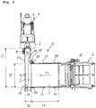
- the adjustable distance sensor SD scans the preforms on the second conveyor belt 4 and thus monitors when the second conveyor belt 4 over the width B1 of the first conveyor belt 3 (possibly also up to approximately the level of the downstream end of the slope 5, ie the lateral bevel 5a ) is free of preforms. As long as this is not the case, no further preforms are delivered to the second conveyor belt 4 by the first conveyor belt 3.
- the first conveyor belt 3 is restarted to deliver preforms.
- the preform carpet on the first conveyor belt 3 is thus controlled by the speed.
- the drive 10 of the first conveyor belt insofar comprises a start-stop mechanism.
- a further sensor S4 is preferably arranged in the region of the downstream end of the bevel 5.
- the speed of the second conveyor belt 4 can be regulated.
- the speed of the second conveyor 4 is increased.
- the speed of the second conveyor 4 is lowered. In this way, an optimally uniform regulation of the preform amount can be ensured without loss of time.
- the (further) sensor S4 should preferably be mounted near the transfer to the backpack silo 6, so that no preforms are "injected” into the backpack silo 6 when switching over to fast operation.
- the Frequency converter setting may be selected so that a fast, slow or constant belt speed is possible.
- the bevel 5 extends at least over the entire width B1 of the first conveyor belt 3 and more preferably approximately to the middle or to half of the width B2 of the second conveyor belt 4.
- the distance sensor SD can in this regard, depending on the preform size laterally along the rear wall 19 are added.
- the rear wall 19 is preferably designed to be folded down in order to be able to serve the same in a reversing operation of the second conveyor belt 4 for emptying.
- the slope 5 usually has a length which is slightly larger than the width B1 of the first conveyor belt 3, since the slope 5 at its downstream end still has a lateral bevel 5a, from which the preforms T2 slipping obliquely forward to ensure a smoother movement of the preform carpet on the second conveyor belt 4.
- the length L1 of the first conveyor belt 3 is between 2000 mm and 3000 mm, preferably between 2250 mm and 2750 mm.
- the width B1 of the first conveyor belt 3 is between 1500 mm and 3500 mm, preferably between 2000 mm and 3000 mm.
- the length L2 of the second conveyor belt 4 is between 2000 mm and 5000 mm, preferably between 2500 mm and 4000 mm.
- the width B2 of the second conveyor belt 4 is between 200 mm and 1000 mm, preferably between 200 and 500 mm.
- Fig. 3 can be seen again in the side view, the arrangement of the sensor S4 in the side wall 16 of the second conveyor belt 4 and the arrangement of the maximum sensor S5 and the minimum sensor S6 in the side wall of the backpack silo. 6
- the backpack silo 6 functions as a buffer device and ensures that the high-level conveyor 7 can continue to supply preforms to downstream units if a correspondingly large gap arises on the first or second conveyor belt.
- the backpack silo 6 has at least one maximum sensor S5 for the filling level with preforms. If the maximum level is reached, the second conveyor belt 4 and possibly also the first conveyor belt 3 is stopped. If the maximum sensor S5 is free, it will continue to be conveyed.
- the backpack silo 6 may optionally have a minimum sensor S6. When the minimum level is reached, the second and possibly also the first conveyor belt 3, 4 are driven at a higher speed, so that the high-level conveyor 7 can be supplied as continuously as possible with preforms.
Landscapes
- Engineering & Computer Science (AREA)
- Mechanical Engineering (AREA)
- Manufacturing & Machinery (AREA)
- Robotics (AREA)
- Control Of Conveyors (AREA)
- Blow-Moulding Or Thermoforming Of Plastics Or The Like (AREA)
- Processing And Handling Of Plastics And Other Materials For Molding In General (AREA)
Priority Applications (3)
| Application Number | Priority Date | Filing Date | Title |
|---|---|---|---|
| EP18152394.5A EP3514085B1 (fr) | 2018-01-18 | 2018-01-18 | Unité de transport et d'alimentation pour préformés |
| US16/242,235 US20190217523A1 (en) | 2018-01-18 | 2019-01-08 | Transfer and feed unit for parisons |
| CN201910033625.0A CN110053194A (zh) | 2018-01-18 | 2019-01-15 | 用于预成型件的运输和供应单元 |
Applications Claiming Priority (1)
| Application Number | Priority Date | Filing Date | Title |
|---|---|---|---|
| EP18152394.5A EP3514085B1 (fr) | 2018-01-18 | 2018-01-18 | Unité de transport et d'alimentation pour préformés |
Publications (3)
| Publication Number | Publication Date |
|---|---|
| EP3514085A1 true EP3514085A1 (fr) | 2019-07-24 |
| EP3514085B1 EP3514085B1 (fr) | 2023-11-08 |
| EP3514085C0 EP3514085C0 (fr) | 2023-11-08 |
Family
ID=61007547
Family Applications (1)
| Application Number | Title | Priority Date | Filing Date |
|---|---|---|---|
| EP18152394.5A Active EP3514085B1 (fr) | 2018-01-18 | 2018-01-18 | Unité de transport et d'alimentation pour préformés |
Country Status (3)
| Country | Link |
|---|---|
| US (1) | US20190217523A1 (fr) |
| EP (1) | EP3514085B1 (fr) |
| CN (1) | CN110053194A (fr) |
Cited By (1)
| Publication number | Priority date | Publication date | Assignee | Title |
|---|---|---|---|---|
| EP3954529A1 (fr) * | 2020-08-14 | 2022-02-16 | Krones Ag | Dispositif et procédé de traitement des préformes en matière plastique pourvu de dispositif d'inspection |
Citations (10)
| Publication number | Priority date | Publication date | Assignee | Title |
|---|---|---|---|---|
| US2237345A (en) * | 1939-06-26 | 1941-04-08 | Heil Co | Receptacle transfer mechanism |
| DE3340088A1 (de) * | 1983-11-05 | 1985-08-29 | Seitz Enzinger Noll Maschinenbau Ag, 6800 Mannheim | Vorrichtung zum drucklosen umformen eines breiten flaschenstroms zu einem einspurigen flaschenstrom |
| US5170879A (en) * | 1991-04-10 | 1992-12-15 | Simplimatic Engineering Company | Single file conveyor system |
| DE19530626A1 (de) * | 1995-08-21 | 1997-02-27 | Kronseder Maschf Krones | Verfahren und Vorrichtung zum Erfassen der Belegung eines Förderers für Gefäße |
| DE20308513U1 (de) | 2003-05-30 | 2004-07-08 | Krones Ag | Vorrichtung zum Zuführen von Vorformlingen zu einer Blasmaschine |
| EP1647506A1 (fr) * | 2004-10-14 | 2006-04-19 | MARCHESINI GROUP S.p.A. | Dispositif pour transformer un flux à plusieurs rangées d'objets en position verticale, notamment de bouteilles, en une seule rangée |
| US7510363B2 (en) * | 2006-02-24 | 2009-03-31 | Northrop Grumman Systems Corporation | Bundle handling device |
| WO2012126129A1 (fr) | 2011-03-24 | 2012-09-27 | M. Tanner Ag | Dispositif destiné à charger une installation de transport avec une grande quantité d'éléments |
| DE102013106926A1 (de) * | 2013-07-02 | 2015-01-08 | Khs Gmbh | Verfahren zur Erfassung des Füllgrades einer Transportstrecke |
| WO2015140451A1 (fr) * | 2014-03-18 | 2015-09-24 | Gebo Packaging Solutions France | Dispositif et procede de convoyage a regulation |
Family Cites Families (7)
| Publication number | Priority date | Publication date | Assignee | Title |
|---|---|---|---|---|
| US1911119A (en) * | 1928-05-04 | 1933-05-23 | Hartford Empire Co | Glassware forming machine |
| US6241072B1 (en) * | 1999-05-24 | 2001-06-05 | Advanced Manufacturing Technology | Bottle manufacturing hopper system |
| DE602005018451D1 (de) * | 2004-02-20 | 2010-02-04 | Scanvaegt Int As | Verfahren und vorrichtung zum portionsschneiden von lebensmitteln oder dergleichen |
| DE102007016453B4 (de) * | 2007-03-30 | 2009-01-08 | SSI Schäfer Noell GmbH Lager- und Systemtechnik | Automatisiertes Kommissioniersystem mit integrierter Sortierfunktion und Verfahren zum Betreiben desselben |
| ITBO20110691A1 (it) * | 2011-12-02 | 2013-06-03 | Ativa | Linea e procedimento di imbottigliamento in ciclo continuo di contenitori in materiale termoplastico. |
| JP6706918B2 (ja) * | 2013-02-08 | 2020-06-10 | トムラ・システムズ・エイ・エス・エイ | バルク供給(bulkfeed) |
| CN107697599B (zh) * | 2017-10-25 | 2024-05-10 | 东富龙科技集团股份有限公司 | 一种烘箱出瓶分配联动控制装置 |
-
2018
- 2018-01-18 EP EP18152394.5A patent/EP3514085B1/fr active Active
-
2019
- 2019-01-08 US US16/242,235 patent/US20190217523A1/en not_active Abandoned
- 2019-01-15 CN CN201910033625.0A patent/CN110053194A/zh active Pending
Patent Citations (10)
| Publication number | Priority date | Publication date | Assignee | Title |
|---|---|---|---|---|
| US2237345A (en) * | 1939-06-26 | 1941-04-08 | Heil Co | Receptacle transfer mechanism |
| DE3340088A1 (de) * | 1983-11-05 | 1985-08-29 | Seitz Enzinger Noll Maschinenbau Ag, 6800 Mannheim | Vorrichtung zum drucklosen umformen eines breiten flaschenstroms zu einem einspurigen flaschenstrom |
| US5170879A (en) * | 1991-04-10 | 1992-12-15 | Simplimatic Engineering Company | Single file conveyor system |
| DE19530626A1 (de) * | 1995-08-21 | 1997-02-27 | Kronseder Maschf Krones | Verfahren und Vorrichtung zum Erfassen der Belegung eines Förderers für Gefäße |
| DE20308513U1 (de) | 2003-05-30 | 2004-07-08 | Krones Ag | Vorrichtung zum Zuführen von Vorformlingen zu einer Blasmaschine |
| EP1647506A1 (fr) * | 2004-10-14 | 2006-04-19 | MARCHESINI GROUP S.p.A. | Dispositif pour transformer un flux à plusieurs rangées d'objets en position verticale, notamment de bouteilles, en une seule rangée |
| US7510363B2 (en) * | 2006-02-24 | 2009-03-31 | Northrop Grumman Systems Corporation | Bundle handling device |
| WO2012126129A1 (fr) | 2011-03-24 | 2012-09-27 | M. Tanner Ag | Dispositif destiné à charger une installation de transport avec une grande quantité d'éléments |
| DE102013106926A1 (de) * | 2013-07-02 | 2015-01-08 | Khs Gmbh | Verfahren zur Erfassung des Füllgrades einer Transportstrecke |
| WO2015140451A1 (fr) * | 2014-03-18 | 2015-09-24 | Gebo Packaging Solutions France | Dispositif et procede de convoyage a regulation |
Cited By (3)
| Publication number | Priority date | Publication date | Assignee | Title |
|---|---|---|---|---|
| EP3954529A1 (fr) * | 2020-08-14 | 2022-02-16 | Krones Ag | Dispositif et procédé de traitement des préformes en matière plastique pourvu de dispositif d'inspection |
| US20220048236A1 (en) * | 2020-08-14 | 2022-02-17 | Krones Ag | Apparatus and method for treating plastic preforms with inspection device |
| US11999093B2 (en) | 2020-08-14 | 2024-06-04 | Krones Ag | Apparatus and method for treating plastic preforms with inspection device |
Also Published As
| Publication number | Publication date |
|---|---|
| CN110053194A (zh) | 2019-07-26 |
| EP3514085B1 (fr) | 2023-11-08 |
| US20190217523A1 (en) | 2019-07-18 |
| EP3514085C0 (fr) | 2023-11-08 |
Similar Documents
| Publication | Publication Date | Title |
|---|---|---|
| DE60318496T2 (de) | Maschine zur lieferung/ausgabe von länglichen gegenständen wie länglichen behältern | |
| EP2321206B1 (fr) | Dispositif de stockage intermédiaire et procédé pour son fonctionnement | |
| EP3447010A1 (fr) | Transporteur pourvu de dispositifs de transport parallèles et réglables en hauteur | |
| EP1952706A1 (fr) | Magasin de vidage et procédé de vidage de récipients remplis de produits en forme de tige, en particulier récipients en forme de colonne | |
| EP2412650A1 (fr) | Dispositif de stockage pour récipients et procédé de stockage de récipients | |
| EP1868923B1 (fr) | Dispositif de transport comprenant au moins une glissiere pour des articles de detail et procede pour empiler des articles de detail dans un conteneur | |
| EP2120615B1 (fr) | Magasin de vidage pour un dispositif de vidage de conteneur conçu pour vider des conteneurs remplis de produits en forme de tige | |
| EP1099632B1 (fr) | Procédé et dispositif pour alimenter des articles plats vers leur séparation individuelle | |
| DE4136498A1 (de) | Einrichtung zur gerichteten zufuhr von tabakrippen zu einem schneidegeraet | |
| DE10133805B4 (de) | Einrichtung zum Zuführen von Bauteilen zu einer Montagestation | |
| EP3514085B1 (fr) | Unité de transport et d'alimentation pour préformés | |
| EP3453651B1 (fr) | Unité de transport et d'alimentation pour préformes | |
| DE4342084C2 (de) | Vorrrichtung zum Ausrichten von Gegenständen | |
| EP4269288A2 (fr) | Dispositif de transport et procédé de transport d'applicateurs de tampon | |
| EP4326523B1 (fr) | Dispositif d'alimentation | |
| DE4413017A1 (de) | Fördersystem, insb. für Befestigungsmittel wie Schrauben oder dergleichen | |
| DE10151971A1 (de) | Schneckensingulator | |
| EP1328170B1 (fr) | Contenant, dispositif et procede pour transporter des articles de forme allongee dans l'industrie du tabac | |
| DE60201314T2 (de) | Vorrichtung zum Zuführen von teilchenförmigem Gut für Anlagen zur Herstellung von gefüllten Keksen | |
| WO2012055761A1 (fr) | Dispositif et procédé d'amortissement de plusieurs produits ou groupes de produits et installation de manipulation de papier dotée dudit dispositif | |
| EP1522509B1 (fr) | Appareil d'empilage de produits plats | |
| EP3135128A2 (fr) | Station de vidage de baquets destinée à vider des baquets remplis de produits en forme de tige et procédé pour vider des baquets remplis de produits en forme de tige à l'aide d'une station de vidage de baquets | |
| DE19720545B4 (de) | Vorrichtung zum Transport von Wickeln und leeren Hülsen | |
| CH695494A5 (de) | Kettenspeicher sowie Verfahren zu dessen Entladung. | |
| DE102006053687A1 (de) | Speichervorrichtung und Verfahren zum Vermindern eines lokalen Drucks in einer Speichervorrichtung |
Legal Events
| Date | Code | Title | Description |
|---|---|---|---|
| PUAI | Public reference made under article 153(3) epc to a published international application that has entered the european phase |
Free format text: ORIGINAL CODE: 0009012 |
|
| STAA | Information on the status of an ep patent application or granted ep patent |
Free format text: STATUS: THE APPLICATION HAS BEEN PUBLISHED |
|
| AK | Designated contracting states |
Kind code of ref document: A1 Designated state(s): AL AT BE BG CH CY CZ DE DK EE ES FI FR GB GR HR HU IE IS IT LI LT LU LV MC MK MT NL NO PL PT RO RS SE SI SK SM TR |
|
| AX | Request for extension of the european patent |
Extension state: BA ME |
|
| STAA | Information on the status of an ep patent application or granted ep patent |
Free format text: STATUS: REQUEST FOR EXAMINATION WAS MADE |
|
| 17P | Request for examination filed |
Effective date: 20200124 |
|
| RBV | Designated contracting states (corrected) |
Designated state(s): AL AT BE BG CH CY CZ DE DK EE ES FI FR GB GR HR HU IE IS IT LI LT LU LV MC MK MT NL NO PL PT RO RS SE SI SK SM TR |
|
| RAP3 | Party data changed (applicant data changed or rights of an application transferred) |
Owner name: M. TANNER AG |
|
| GRAP | Despatch of communication of intention to grant a patent |
Free format text: ORIGINAL CODE: EPIDOSNIGR1 |
|
| STAA | Information on the status of an ep patent application or granted ep patent |
Free format text: STATUS: GRANT OF PATENT IS INTENDED |
|
| INTG | Intention to grant announced |
Effective date: 20221129 |
|
| GRAJ | Information related to disapproval of communication of intention to grant by the applicant or resumption of examination proceedings by the epo deleted |
Free format text: ORIGINAL CODE: EPIDOSDIGR1 |
|
| STAA | Information on the status of an ep patent application or granted ep patent |
Free format text: STATUS: REQUEST FOR EXAMINATION WAS MADE |
|
| INTC | Intention to grant announced (deleted) | ||
| GRAP | Despatch of communication of intention to grant a patent |
Free format text: ORIGINAL CODE: EPIDOSNIGR1 |
|
| STAA | Information on the status of an ep patent application or granted ep patent |
Free format text: STATUS: GRANT OF PATENT IS INTENDED |
|
| INTG | Intention to grant announced |
Effective date: 20230519 |
|
| GRAS | Grant fee paid |
Free format text: ORIGINAL CODE: EPIDOSNIGR3 |
|
| GRAA | (expected) grant |
Free format text: ORIGINAL CODE: 0009210 |
|
| STAA | Information on the status of an ep patent application or granted ep patent |
Free format text: STATUS: THE PATENT HAS BEEN GRANTED |
|
| AK | Designated contracting states |
Kind code of ref document: B1 Designated state(s): AL AT BE BG CH CY CZ DE DK EE ES FI FR GB GR HR HU IE IS IT LI LT LU LV MC MK MT NL NO PL PT RO RS SE SI SK SM TR |
|
| REG | Reference to a national code |
Ref country code: GB Ref legal event code: FG4D Free format text: NOT ENGLISH |
|
| REG | Reference to a national code |
Ref country code: CH Ref legal event code: EP |
|
| REG | Reference to a national code |
Ref country code: DE Ref legal event code: R096 Ref document number: 502018013590 Country of ref document: DE |
|
| REG | Reference to a national code |
Ref country code: IE Ref legal event code: FG4D Free format text: LANGUAGE OF EP DOCUMENT: GERMAN |
|
| U01 | Request for unitary effect filed |
Effective date: 20231208 |
|
| U07 | Unitary effect registered |
Designated state(s): AT BE BG DE DK EE FI FR IT LT LU LV MT NL PT SE SI Effective date: 20231214 |
|
| U20 | Renewal fee for the european patent with unitary effect paid |
Year of fee payment: 7 Effective date: 20240122 |
|
| PG25 | Lapsed in a contracting state [announced via postgrant information from national office to epo] |
Ref country code: GR Free format text: LAPSE BECAUSE OF FAILURE TO SUBMIT A TRANSLATION OF THE DESCRIPTION OR TO PAY THE FEE WITHIN THE PRESCRIBED TIME-LIMIT Effective date: 20240209 |
|
| PG25 | Lapsed in a contracting state [announced via postgrant information from national office to epo] |
Ref country code: IS Free format text: LAPSE BECAUSE OF FAILURE TO SUBMIT A TRANSLATION OF THE DESCRIPTION OR TO PAY THE FEE WITHIN THE PRESCRIBED TIME-LIMIT Effective date: 20240308 |
|
| PG25 | Lapsed in a contracting state [announced via postgrant information from national office to epo] |
Ref country code: ES Free format text: LAPSE BECAUSE OF FAILURE TO SUBMIT A TRANSLATION OF THE DESCRIPTION OR TO PAY THE FEE WITHIN THE PRESCRIBED TIME-LIMIT Effective date: 20231108 |
|
| PG25 | Lapsed in a contracting state [announced via postgrant information from national office to epo] |
Ref country code: IS Free format text: LAPSE BECAUSE OF FAILURE TO SUBMIT A TRANSLATION OF THE DESCRIPTION OR TO PAY THE FEE WITHIN THE PRESCRIBED TIME-LIMIT Effective date: 20240308 Ref country code: GR Free format text: LAPSE BECAUSE OF FAILURE TO SUBMIT A TRANSLATION OF THE DESCRIPTION OR TO PAY THE FEE WITHIN THE PRESCRIBED TIME-LIMIT Effective date: 20240209 Ref country code: ES Free format text: LAPSE BECAUSE OF FAILURE TO SUBMIT A TRANSLATION OF THE DESCRIPTION OR TO PAY THE FEE WITHIN THE PRESCRIBED TIME-LIMIT Effective date: 20231108 |
|
| PG25 | Lapsed in a contracting state [announced via postgrant information from national office to epo] |
Ref country code: RS Free format text: LAPSE BECAUSE OF FAILURE TO SUBMIT A TRANSLATION OF THE DESCRIPTION OR TO PAY THE FEE WITHIN THE PRESCRIBED TIME-LIMIT Effective date: 20231108 Ref country code: PL Free format text: LAPSE BECAUSE OF FAILURE TO SUBMIT A TRANSLATION OF THE DESCRIPTION OR TO PAY THE FEE WITHIN THE PRESCRIBED TIME-LIMIT Effective date: 20231108 Ref country code: NO Free format text: LAPSE BECAUSE OF FAILURE TO SUBMIT A TRANSLATION OF THE DESCRIPTION OR TO PAY THE FEE WITHIN THE PRESCRIBED TIME-LIMIT Effective date: 20240208 Ref country code: HR Free format text: LAPSE BECAUSE OF FAILURE TO SUBMIT A TRANSLATION OF THE DESCRIPTION OR TO PAY THE FEE WITHIN THE PRESCRIBED TIME-LIMIT Effective date: 20231108 |
|
| PG25 | Lapsed in a contracting state [announced via postgrant information from national office to epo] |
Ref country code: CZ Free format text: LAPSE BECAUSE OF FAILURE TO SUBMIT A TRANSLATION OF THE DESCRIPTION OR TO PAY THE FEE WITHIN THE PRESCRIBED TIME-LIMIT Effective date: 20231108 |
|
| PG25 | Lapsed in a contracting state [announced via postgrant information from national office to epo] |
Ref country code: SK Free format text: LAPSE BECAUSE OF FAILURE TO SUBMIT A TRANSLATION OF THE DESCRIPTION OR TO PAY THE FEE WITHIN THE PRESCRIBED TIME-LIMIT Effective date: 20231108 |
|
| PG25 | Lapsed in a contracting state [announced via postgrant information from national office to epo] |
Ref country code: SM Free format text: LAPSE BECAUSE OF FAILURE TO SUBMIT A TRANSLATION OF THE DESCRIPTION OR TO PAY THE FEE WITHIN THE PRESCRIBED TIME-LIMIT Effective date: 20231108 Ref country code: SK Free format text: LAPSE BECAUSE OF FAILURE TO SUBMIT A TRANSLATION OF THE DESCRIPTION OR TO PAY THE FEE WITHIN THE PRESCRIBED TIME-LIMIT Effective date: 20231108 Ref country code: RO Free format text: LAPSE BECAUSE OF FAILURE TO SUBMIT A TRANSLATION OF THE DESCRIPTION OR TO PAY THE FEE WITHIN THE PRESCRIBED TIME-LIMIT Effective date: 20231108 Ref country code: CZ Free format text: LAPSE BECAUSE OF FAILURE TO SUBMIT A TRANSLATION OF THE DESCRIPTION OR TO PAY THE FEE WITHIN THE PRESCRIBED TIME-LIMIT Effective date: 20231108 |
|
| REG | Reference to a national code |
Ref country code: DE Ref legal event code: R097 Ref document number: 502018013590 Country of ref document: DE |
|
| PG25 | Lapsed in a contracting state [announced via postgrant information from national office to epo] |
Ref country code: MC Free format text: LAPSE BECAUSE OF FAILURE TO SUBMIT A TRANSLATION OF THE DESCRIPTION OR TO PAY THE FEE WITHIN THE PRESCRIBED TIME-LIMIT Effective date: 20231108 |
|
| PG25 | Lapsed in a contracting state [announced via postgrant information from national office to epo] |
Ref country code: MC Free format text: LAPSE BECAUSE OF FAILURE TO SUBMIT A TRANSLATION OF THE DESCRIPTION OR TO PAY THE FEE WITHIN THE PRESCRIBED TIME-LIMIT Effective date: 20231108 |
|
| PLBE | No opposition filed within time limit |
Free format text: ORIGINAL CODE: 0009261 |
|
| STAA | Information on the status of an ep patent application or granted ep patent |
Free format text: STATUS: NO OPPOSITION FILED WITHIN TIME LIMIT |
|
| 26N | No opposition filed |
Effective date: 20240809 |
|
| GBPC | Gb: european patent ceased through non-payment of renewal fee |
Effective date: 20240208 |
|
| PG25 | Lapsed in a contracting state [announced via postgrant information from national office to epo] |
Ref country code: GB Free format text: LAPSE BECAUSE OF NON-PAYMENT OF DUE FEES Effective date: 20240208 |
|
| PG25 | Lapsed in a contracting state [announced via postgrant information from national office to epo] |
Ref country code: IE Free format text: LAPSE BECAUSE OF NON-PAYMENT OF DUE FEES Effective date: 20240118 |
|
| PG25 | Lapsed in a contracting state [announced via postgrant information from national office to epo] |
Ref country code: IE Free format text: LAPSE BECAUSE OF NON-PAYMENT OF DUE FEES Effective date: 20240118 Ref country code: GB Free format text: LAPSE BECAUSE OF NON-PAYMENT OF DUE FEES Effective date: 20240208 |
|
| U20 | Renewal fee for the european patent with unitary effect paid |
Year of fee payment: 8 Effective date: 20250116 |
|
| PG25 | Lapsed in a contracting state [announced via postgrant information from national office to epo] |
Ref country code: CY Free format text: LAPSE BECAUSE OF FAILURE TO SUBMIT A TRANSLATION OF THE DESCRIPTION OR TO PAY THE FEE WITHIN THE PRESCRIBED TIME-LIMIT; INVALID AB INITIO Effective date: 20180118 |
|
| PG25 | Lapsed in a contracting state [announced via postgrant information from national office to epo] |
Ref country code: HU Free format text: LAPSE BECAUSE OF FAILURE TO SUBMIT A TRANSLATION OF THE DESCRIPTION OR TO PAY THE FEE WITHIN THE PRESCRIBED TIME-LIMIT; INVALID AB INITIO Effective date: 20180118 |
|
| PG25 | Lapsed in a contracting state [announced via postgrant information from national office to epo] |
Ref country code: TR Free format text: LAPSE BECAUSE OF FAILURE TO SUBMIT A TRANSLATION OF THE DESCRIPTION OR TO PAY THE FEE WITHIN THE PRESCRIBED TIME-LIMIT Effective date: 20231108 |
|
| REG | Reference to a national code |
Ref country code: CH Ref legal event code: U11 Free format text: ST27 STATUS EVENT CODE: U-0-0-U10-U11 (AS PROVIDED BY THE NATIONAL OFFICE) Effective date: 20260201 |
|
| U20 | Renewal fee for the european patent with unitary effect paid |
Year of fee payment: 9 Effective date: 20260114 |
|
| PGFP | Annual fee paid to national office [announced via postgrant information from national office to epo] |
Ref country code: CH Payment date: 20260201 Year of fee payment: 9 |