EP3514248A1 - Tuyère d'agitation par le fond et procédé pour piloter un four à oxygène basique - Google Patents
Tuyère d'agitation par le fond et procédé pour piloter un four à oxygène basique Download PDFInfo
- Publication number
- EP3514248A1 EP3514248A1 EP19151184.9A EP19151184A EP3514248A1 EP 3514248 A1 EP3514248 A1 EP 3514248A1 EP 19151184 A EP19151184 A EP 19151184A EP 3514248 A1 EP3514248 A1 EP 3514248A1
- Authority
- EP
- European Patent Office
- Prior art keywords
- tuyere
- nozzle
- flow
- reactant
- inert gas
- Prior art date
- Legal status (The legal status is an assumption and is not a legal conclusion. Google has not performed a legal analysis and makes no representation as to the accuracy of the status listed.)
- Granted
Links
Images




Classifications
-
- C—CHEMISTRY; METALLURGY
- C21—METALLURGY OF IRON
- C21C—PROCESSING OF PIG-IRON, e.g. REFINING, MANUFACTURE OF WROUGHT-IRON OR STEEL; TREATMENT IN MOLTEN STATE OF FERROUS ALLOYS
- C21C5/00—Manufacture of carbon-steel, e.g. plain mild steel, medium carbon steel or cast steel or stainless steel
- C21C5/56—Manufacture of steel by other methods
-
- C—CHEMISTRY; METALLURGY
- C21—METALLURGY OF IRON
- C21C—PROCESSING OF PIG-IRON, e.g. REFINING, MANUFACTURE OF WROUGHT-IRON OR STEEL; TREATMENT IN MOLTEN STATE OF FERROUS ALLOYS
- C21C5/00—Manufacture of carbon-steel, e.g. plain mild steel, medium carbon steel or cast steel or stainless steel
- C21C5/28—Manufacture of steel in the converter
- C21C5/42—Constructional features of converters
- C21C5/46—Details or accessories
- C21C5/48—Bottoms or tuyéres of converters
-
- B—PERFORMING OPERATIONS; TRANSPORTING
- B22—CASTING; POWDER METALLURGY
- B22D—CASTING OF METALS; CASTING OF OTHER SUBSTANCES BY THE SAME PROCESSES OR DEVICES
- B22D1/00—Treatment of fused masses in the ladle or the supply runners before casting
- B22D1/002—Treatment with gases
- B22D1/005—Injection assemblies therefor
-
- C—CHEMISTRY; METALLURGY
- C21—METALLURGY OF IRON
- C21C—PROCESSING OF PIG-IRON, e.g. REFINING, MANUFACTURE OF WROUGHT-IRON OR STEEL; TREATMENT IN MOLTEN STATE OF FERROUS ALLOYS
- C21C1/00—Refining of pig-iron; Cast iron
- C21C1/06—Constructional features of mixers for pig-iron
-
- C—CHEMISTRY; METALLURGY
- C21—METALLURGY OF IRON
- C21C—PROCESSING OF PIG-IRON, e.g. REFINING, MANUFACTURE OF WROUGHT-IRON OR STEEL; TREATMENT IN MOLTEN STATE OF FERROUS ALLOYS
- C21C5/00—Manufacture of carbon-steel, e.g. plain mild steel, medium carbon steel or cast steel or stainless steel
- C21C5/28—Manufacture of steel in the converter
- C21C5/30—Regulating or controlling the blowing
- C21C5/34—Blowing through the bath
-
- C—CHEMISTRY; METALLURGY
- C21—METALLURGY OF IRON
- C21C—PROCESSING OF PIG-IRON, e.g. REFINING, MANUFACTURE OF WROUGHT-IRON OR STEEL; TREATMENT IN MOLTEN STATE OF FERROUS ALLOYS
- C21C5/00—Manufacture of carbon-steel, e.g. plain mild steel, medium carbon steel or cast steel or stainless steel
- C21C5/28—Manufacture of steel in the converter
- C21C5/30—Regulating or controlling the blowing
- C21C5/35—Blowing from above and through the bath
-
- C—CHEMISTRY; METALLURGY
- C21—METALLURGY OF IRON
- C21C—PROCESSING OF PIG-IRON, e.g. REFINING, MANUFACTURE OF WROUGHT-IRON OR STEEL; TREATMENT IN MOLTEN STATE OF FERROUS ALLOYS
- C21C7/00—Treating molten ferrous alloys, e.g. steel, not covered by groups C21C1/00 - C21C5/00
- C21C7/04—Removing impurities by adding a treating agent
- C21C7/072—Treatment with gases
-
- F—MECHANICAL ENGINEERING; LIGHTING; HEATING; WEAPONS; BLASTING
- F27—FURNACES; KILNS; OVENS; RETORTS
- F27D—DETAILS OR ACCESSORIES OF FURNACES, KILNS, OVENS OR RETORTS, IN SO FAR AS THEY ARE OF KINDS OCCURRING IN MORE THAN ONE KIND OF FURNACE
- F27D3/00—Charging; Discharging; Manipulation of charge
- F27D3/16—Introducing a fluid jet or current into the charge
-
- C—CHEMISTRY; METALLURGY
- C21—METALLURGY OF IRON
- C21C—PROCESSING OF PIG-IRON, e.g. REFINING, MANUFACTURE OF WROUGHT-IRON OR STEEL; TREATMENT IN MOLTEN STATE OF FERROUS ALLOYS
- C21C2300/00—Process aspects
- C21C2300/08—Particular sequence of the process steps
-
- F—MECHANICAL ENGINEERING; LIGHTING; HEATING; WEAPONS; BLASTING
- F27—FURNACES; KILNS; OVENS; RETORTS
- F27D—DETAILS OR ACCESSORIES OF FURNACES, KILNS, OVENS OR RETORTS, IN SO FAR AS THEY ARE OF KINDS OCCURRING IN MORE THAN ONE KIND OF FURNACE
- F27D3/00—Charging; Discharging; Manipulation of charge
- F27D3/16—Introducing a fluid jet or current into the charge
- F27D2003/162—Introducing a fluid jet or current into the charge the fluid being an oxidant or a fuel
-
- F—MECHANICAL ENGINEERING; LIGHTING; HEATING; WEAPONS; BLASTING
- F27—FURNACES; KILNS; OVENS; RETORTS
- F27D—DETAILS OR ACCESSORIES OF FURNACES, KILNS, OVENS OR RETORTS, IN SO FAR AS THEY ARE OF KINDS OCCURRING IN MORE THAN ONE KIND OF FURNACE
- F27D3/00—Charging; Discharging; Manipulation of charge
- F27D3/16—Introducing a fluid jet or current into the charge
- F27D2003/167—Introducing a fluid jet or current into the charge the fluid being a neutral gas
-
- F—MECHANICAL ENGINEERING; LIGHTING; HEATING; WEAPONS; BLASTING
- F27—FURNACES; KILNS; OVENS; RETORTS
- F27D—DETAILS OR ACCESSORIES OF FURNACES, KILNS, OVENS OR RETORTS, IN SO FAR AS THEY ARE OF KINDS OCCURRING IN MORE THAN ONE KIND OF FURNACE
- F27D27/00—Stirring devices for molten material
- F27D2027/002—Gas stirring
-
- F—MECHANICAL ENGINEERING; LIGHTING; HEATING; WEAPONS; BLASTING
- F27—FURNACES; KILNS; OVENS; RETORTS
- F27D—DETAILS OR ACCESSORIES OF FURNACES, KILNS, OVENS OR RETORTS, IN SO FAR AS THEY ARE OF KINDS OCCURRING IN MORE THAN ONE KIND OF FURNACE
- F27D99/00—Subject matter not provided for in other groups of this subclass
- F27D99/0001—Heating elements or systems
- F27D99/0033—Heating elements or systems using burners
- F27D2099/0036—Heating elements or systems using burners immersed in the charge
Definitions
- This application relates to a tuyere and a method for improving the operability using inert gas to bottom stir a basic oxygen furnace (BOF).
- BOF basic oxygen furnace
- BOF's have been commonly used since the mid-20 th century to convert pig iron into steel, primarily by the use of oxygen to remove carbon and impurities.
- the BOF was an improvement over the earlier Bessemer process that blew air into the pig iron to accomplish the conversion.
- blowing oxygen through molten pig iron lowers the carbon content of the metal and changes it into low-carbon steel.
- the process also uses fluxes of burnt lime or dolomite, which are chemical bases, to promote the removal of impurities and protect the lining of the vessel.
- oxygen is blown at supersonic velocity into the bath using a top lance, which causes an exothermic reaction of oxygen and carbon, thereby generating heat and removing carbon.
- the ingredients, including oxygen, are modeled and the precise amount of oxygen is blown so that the target chemistry and temperature are reached within about 20 minutes.
- bottom stirring which may also be called combined blowing
- stirring the molten metal by introduction of gas from below improves the kinetics and makes the temperature more homogeneous, enabling better control over the carbon-oxygen ratio and the removal of phosphorous.
- BOF bottom stirring It is relatively common outside of the US to use an inert gas, such as argon and/or nitrogen, for bottom stirring. Benefits of BOF bottom stirring include potentially higher yield and increased energy efficiency. However, BOF bottom stirring is not common in the US because of the poor reliability and difficulty maintaining the bottom stirring nozzles due to slag splashing practices commonly used in the US. Slag splashing helps improve refractory and vessel lifetime, but causes blockage of existing bottom stirring nozzles.
- inert gas such as argon and/or nitrogen
- the inert gas flows are maintained at high flow rates all the time, even when bottom stirring is not needed to combat the potential for clogging, which is inefficient and uses excessive amounts of inert gases. See, for example, Mills, Kenneth C., et al. "A review of slag splashing.” ISIJ international 45.5 (2005): 619-633 ); and https://www.jstage.jst.go.jp/article/isijinternational/45/5/45_5_619/_pdf.
- slag chemical compositions have been modified in combination with 50% higher flows used for stirring in the event that a clog is detected. See, for example, Guoguang, Zhao & Husken, Rainer & Cappel, Jurgen. (2012), Experience with long BOF campaign life and TBM bottom stirring technology, Stahl und Eisen, 132. 61-78 (which improved tuyere life to 8,000-10,000 cycles).
- these modifications require a great deal of process knowledge and control i.e. addition of MgO pellets and managing the CaO/SiO2 ratio depending on the [C]-[O] levels in the slag.
- oxidant shall mean enriched air or oxygen having a molecular oxygen concentration of at least 23%, preferably at least 70%, and more preferably at least 90%.
- inert gas shall mean nitrogen, argon, carbon-dioxide, other similar inert gases, and combinations thereof.
- fuel shall mean a gaseous fuel, which may include but is not limited to natural gas.
- a typical BOF steel making process has four phases, shown by way of five steps in Fig. 1 : a pour phase (Step 1), a blow phase (started by Step 2 and ended by Step 3), a tap phase (Step 4), and a slag splash phase (Step 5).
- the cycle repeats, so after Step 5, the process recycles to Step 1.
- Step 1 Hot Metal Pour
- hot metal pig iron
- Step 2 Start Blow
- Step 3 End Blow
- Step 4 the furnace is tilted and the molten metal is poured out through a tap on the side of the furnace, while the slag is left behind in the furnace.
- Step 5 the furnace is returned to an upright position and a flow of nitrogen is injected through a lance inserted through the top opening of the furnace.
- the nitrogen is flowed in large quantities (e.g., 20,000 SCFM) at supersonic velocities into the BOF, which causes the molten slag to splash all over the walls of the furnace vessel.
- Slag splashing however, if done in a vessel with bottom stir nozzles, often results in partial or complete clogging of the bottom stir nozzles located at the bottom of the vessel. This clogging, as shown in Fig. 2 , essentially prevents or restricts further flow of gases through the bottom stir nozzles into the BOF, and eventually, after multiple slag splashing, results in losing the ability to bottom stir at all.
- the self-sustaining tuyere is basically a concentric tube design, where one fluid is flowed through the inner central nozzle while another fluid is flowed through the outer annular nozzle.
- the inner central nozzle may sometimes be referred to as the primary nozzle
- the outer annular nozzle may sometimes be referred to as the secondary nozzle.
- the inner central passage is configured to selectively flow either fuel or an inert gas and the outer annular passage is configured to selectively flow either oxygen or an inert gas, depending on the phase of operation of the BOF.
- the inner central passage is configured to selectively flow either oxidant or an inert gas and the outer annular passage is configured to selectively flow either fuel or an inert gas, again depending on the phase of operation of the BOF.
- each stirring tuyere is made up of coaxial nozzles (pipe-in-pipe configuration), for example as shown in Fig. 10 .
- the tuyere is installed in the BOF so that it has an exit end or hot tip facing into the furnace.
- fuel and oxygen or alternatively an inert gas such as nitrogen, argon, or carbon-dioxide, are interchangeably introduced into both the inside and outside nozzles, depending on the phase of operation in the BOF.
- the main role of the primary nozzle is to provide flow regimes that are effective for stirring e.g., jetting flows to prevent back attack.
- the main role of the secondary nozzle is to provide protection to the primary nozzle and enhance interaction with the primary nozzle flows, particular to help stabilize a flame during the slag splashing phase, by use of special features e.g., swirling flows.
- the primary nozzle may have one of several configurations.
- the primary nozzle may be a straight nozzle, a converging-diverging nozzle (to create supersonic flows), a cavity nozzle, or a combination of a converging-diverging nozzle with cavity.
- the nozzle When the primary nozzle is or includes a converging-diverging nozzle, the nozzle should be preferably sized for Mach > 1.25 to ensure jetting flow (see, e.g., Farmer, L., Lach, D., Lanyi, M., Winchester, D., "Gas injection tuyeres design and experience", Steelmaking Conference Proceedings, Pg. 487-495 (1989 )). Jetting flow helps to: (a) prevent back attack on the bottom refractory, and (b) achieve more effective stirring.
- Jetting flow is achieved when there is sufficient gas pressure to develop an underexpanded jet (when pressure of the gas exiting the tuyeres is greater than the pressure or static head of the surrounding fluid) such that a continuous flow of gas (no bubble formation) is generated to prevent periodic backflow of liquid (metal/slag) into the tuyere.
- the cavity should be sized to have a length to diameter (L/D) ratio of 1 to 10, preferably from 1.5 to 2.5.
- L/D ratio a length to diameter ratio of 1 to 10, preferably from 1.5 to 2.5.
- Fig. 11 A detail of a cavity nozzle with these dimensions is shown in Fig. 11 .
- the preferred L/D ratio range helps to: (a) increase the coherence and penetration of the jetting flow for more effective stirring, and (b) improve the stability of the flame over a wide range of firing rates and stoichiometry.
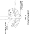
- Figs. 8 and 9 show the improvement in flame stability for a nozzle with cavity ( Fig. 9 ) versus a nozzle without a cavity ( Fig.
- the nozzle is designed to fire at 0.2 MMBtu/hr.
- the cavity nozzle maybe recessed up to a length L R from the hot tip of the primary nozzles to improve the lifetime and maintain the performance of the primary nozzle, wherein L R is measured from the downstream edge of the cavity.
- L R /L is from greater than 0 to about 20, and more preferably from 0.1 to 5.
- the distance between the converging-diverging nozzle and the cavity can be up to a length L D , where L D /L is from greater than 0 to 3, and preferably from 0.1 to 1, and wherein L D is measured from the upstream edge of the cavity to the throat of the converging-diverging nozzle.
- the secondary nozzle should preferably have swirl vanes to induce a swirling flow that enhances the interaction with primary flow and assists with stabilization of the flame during Steps 4 and 5.
- the acute angle ( ⁇ ) of vanes relative to the tuyeres axis maybe from 0 degrees and 90 degrees (see Fig. 10 ), and preferably from 10 degrees to 60 degrees, and more preferably from 15 degrees to 45 degrees.
- the velocity ratio (V P /V S ) between the primary nozzle flow (V P ) and the secondary nozzle flow (V S ) can be from 2 to 30, where V S is the axial component of the secondary flow velocity.
- the self-sustaining tuyeres function in two modes of operation.
- the tuyeres function in a Bottom Stirring (BS) mode, in which inert gases flow through the nozzles at a rate sufficient to achieve effective stirring of the molten steel in the furnace.
- BS Bottom Stirring
- the tuyeres function in a Slag Splashing (SS) mode, in which a combination of fuel and oxidant, and optionally inert gases flow through the tuyere (see Fig. 6 ).
- SS Slag Splashing
- Fig. 7 illustrates the operation strategy of the self-sustaining bottom stir tuyeres, and in particular, illustrates how the proposed process differs from the standard process of BOF steelmaking.
- Steps 1 to 3 the bottom stir tuyeres operate in the bottom stirring mode
- Steps 4 to 5 the bottom stir tuyeres operate in the slag splashing mode.
- Step 1 Hot Metal Pour
- Step 2 Start Blow
- Step 3 End Blow
- the flow of inert gases is continued as during Step 2.
- the most effective results are achieved by flowing inert gases such as argon, nitrogen, carbon-dioxide, or combinations thereof through both the primary nozzle and the secondary nozzle of the tuyere.
- Step 4 when the BOF vessel is tilted to pour the metal out, the flow through the nozzle passages is switched over to fuel through one passage and oxidant through the other passage, to produce a flame (the furnace walls are sufficiently hot to cause auto-ignition of a fuel-oxidant mixture exiting the nozzles). Combustion, in the form of a flame exiting each bottom stir tuyere, must be commenced prior to the start of the slag splashing operation.
- Step 5 the flames prevent the tuyeres from clogging, and also prevent the formation of bridges. Thus, during Steps 4 and 5, fuel and oxidant are introduced through the nozzles.
- oxidant through the primary nozzle and fuel through the secondary nozzle.
- a diluent gas such as nitrogen or air maybe added to the flow through either or both the primary nozzle and the secondary nozzle to help manage the location of heat release (i.e., how far away from the nozzles the bulk of combustion occurs) and the volumes or momentum required to provide the desired flow profile (i.e., adding nitrogen or air increases the volumetric flow rate or momentum). This can be accomplished by adjusting the ratio or relative proportion of diluent gas to oxidant and/or fuel.
- an electrical discharge (plasma arc) maybe used to replace fuel and oxidizer as the source of energy to prevent nozzle clogging during the tap and slag splashing phases.
- an electric discharge would be created between the inner nozzle and the annular nozzle of the tuyere while the flow of inert gas is maintained during those phases operation.
- a preheated (preferably to a temperature greater than 2500 °F) gas stream may be utilized as a source of energy.
- the slag splashing process involves formation of slag droplets (by impingement of a high momentum supersonic jet of nitrogen) followed by rapid convective cooling of the slag droplets (by the same nitrogen flow swirling through the vessel). This process causes an increase in the viscosity and surface tension of the slag, followed by fairly rapid solidification, which thus results in bridging and/or clogging that an inert gas flow alone is not able to prevent.
- the presently described tuyere and method can prevent bridging and clogging of the bottom stir tuyeres during the slag splashing process.
- the primary mechanism to prevent of clogging is by using heat (i.e., the heat of combustion of fuel and oxidant) to simultaneously: (a) lower the viscosity and surface tension of the slag that is local to and surrounds the bottom stir nozzles, and (2) increase viscosity of the gas jets exiting the tuyeres and thermally enhance the momentum of flows through the nozzles.
- thermally managing the viscosity and surface tension of slag at a local level near the tuyeres is more easily accomplished than attempting to alter the chemical composition of all the slag (which may also impact the chemistry of the steel itself).
- thermally enhancing the momentum and viscosity of gas jets provides significant nozzle clearing power as compared with only increasing the flow rate of inert gases.
- Third, utilizing fuel and oxygen only during a specific part of the cycle i.e., Steps 4 and 5 in Fig.
- Sensors may be used to enhance the ability to detect and prevent nozzle clogging.
- pressure transducers are installed at or near the tuyere exit end to detect clogging or bridging of the nozzles, which would cause a backpressure increase.
- Pressure sensors may also be used to detect erosion of the nozzles and damage of the converging-diverging and/or cavity features of the nozzles, as exhibited by variations in pressure drop.
- thermocouples may be installed at or near the tuyere exit end to detect deviation of temperatures from normal operation due to erosion of nozzles and seeping of molten metal through the nozzle.
- a high volume (high pressure) jet may be periodically used to keep the nozzles from clogging or introduced in response to detection of deviation of pressures/temperatures from normal operation.
- Other corrective actions such as bottom-washing of the vessel with oxygen maybe used to unclog the nozzles in a timely manner.
Landscapes
- Chemical & Material Sciences (AREA)
- Engineering & Computer Science (AREA)
- Materials Engineering (AREA)
- Metallurgy (AREA)
- Organic Chemistry (AREA)
- Manufacturing & Machinery (AREA)
- Mechanical Engineering (AREA)
- General Engineering & Computer Science (AREA)
- Treatment Of Steel In Its Molten State (AREA)
- Carbon Steel Or Casting Steel Manufacturing (AREA)
- Refinement Of Pig-Iron, Manufacture Of Cast Iron, And Steel Manufacture Other Than In Revolving Furnaces (AREA)
- Furnace Charging Or Discharging (AREA)
- Vertical, Hearth, Or Arc Furnaces (AREA)
- Manufacture And Refinement Of Metals (AREA)
- Waste-Gas Treatment And Other Accessory Devices For Furnaces (AREA)
Priority Applications (1)
| Application Number | Priority Date | Filing Date | Title |
|---|---|---|---|
| PL19151184T PL3514248T3 (pl) | 2018-01-17 | 2019-01-10 | Dysza do mieszania od dołu i sposób eksploatacji zasadowego konwertora tlenowego |
Applications Claiming Priority (1)
| Application Number | Priority Date | Filing Date | Title |
|---|---|---|---|
| US15/873,616 US10781499B2 (en) | 2018-01-17 | 2018-01-17 | Bottom stirring tuyere and method for a basic oxygen furnace |
Publications (2)
| Publication Number | Publication Date |
|---|---|
| EP3514248A1 true EP3514248A1 (fr) | 2019-07-24 |
| EP3514248B1 EP3514248B1 (fr) | 2021-05-26 |
Family
ID=65013580
Family Applications (1)
| Application Number | Title | Priority Date | Filing Date |
|---|---|---|---|
| EP19151184.9A Active EP3514248B1 (fr) | 2018-01-17 | 2019-01-10 | Tuyère d'agitation par le fond et procédé pour piloter un four à oxygène basique |
Country Status (12)
| Country | Link |
|---|---|
| US (1) | US10781499B2 (fr) |
| EP (1) | EP3514248B1 (fr) |
| KR (1) | KR102249348B1 (fr) |
| CN (1) | CN110042199B (fr) |
| BR (1) | BR102019000862B1 (fr) |
| CA (1) | CA3029689C (fr) |
| ES (1) | ES2878056T3 (fr) |
| HU (1) | HUE054764T2 (fr) |
| MX (1) | MX2019000615A (fr) |
| PL (1) | PL3514248T3 (fr) |
| PT (1) | PT3514248T (fr) |
| TW (1) | TWI681061B (fr) |
Cited By (1)
| Publication number | Priority date | Publication date | Assignee | Title |
|---|---|---|---|---|
| WO2021239161A1 (fr) * | 2020-05-23 | 2021-12-02 | 苏州大学 | Procédé de commande de soufflage permettant de maintenir la tête de champignon d'un convertisseur à pulvérisation par le bas |
Families Citing this family (4)
| Publication number | Priority date | Publication date | Assignee | Title |
|---|---|---|---|---|
| CN111440917A (zh) * | 2020-04-21 | 2020-07-24 | 攀钢集团攀枝花钢铁研究院有限公司 | 一种控制炼钢炉底吹砖和炉底均匀侵蚀的方法 |
| DE102020215076A1 (de) * | 2020-11-30 | 2022-06-02 | Sms Group Gmbh | Verfahren zur Behandlung von Metallschmelzen und/oder Schlacken in metallurgischen Bädern sowie metallurgische Anlage zur Behandlung von Metallschmelzen |
| DE102020215147A1 (de) | 2020-12-01 | 2022-06-02 | Sms Group Gmbh | Verfahren zum pyrometallurgischen Einschmelzen von metallhaltigen Rohstoffen, Reststoffen und/oder Sekundärreststoffen |
| CN114921610B (zh) * | 2022-06-02 | 2023-05-05 | 中天钢铁集团(南通)有限公司 | 一种转炉底吹孔分布结构及其底吹方法 |
Citations (7)
| Publication number | Priority date | Publication date | Assignee | Title |
|---|---|---|---|---|
| FR2228845A1 (en) * | 1973-05-12 | 1974-12-06 | Maximilianshuette Eisenwerk | Tuyere for refining gas e.g. oxygen - for blowing gas below the surface of a melt in a metallurgical vessel |
| GB1486539A (en) * | 1974-10-04 | 1977-09-21 | British Steel Corp | Steelmaking |
| US4365992A (en) * | 1981-08-20 | 1982-12-28 | Pennsylvania Engineering Corporation | Method of treating ferrous metal |
| US4824080A (en) * | 1987-02-24 | 1989-04-25 | Allegheny Ludlum Corporation | Apparatus for introducing gas into molten metal baths |
| US5830407A (en) * | 1996-10-17 | 1998-11-03 | Kvaerner U.S. Inc. | Pressurized port for viewing and measuring properties of a molten metal bath |
| WO2014193390A1 (fr) * | 2013-05-30 | 2014-12-04 | Johns Manville | Brûleurs à combustion immergée comprenant un moyen d'amélioration du mélange pour dispositifs de fusion du verre |
| WO2015200347A1 (fr) * | 2014-06-23 | 2015-12-30 | Air Products And Chemicals, Inc. | Brûleur à combustible oxygène avec mélange actionné par cavité |
Family Cites Families (13)
| Publication number | Priority date | Publication date | Assignee | Title |
|---|---|---|---|---|
| US4023781A (en) * | 1973-05-12 | 1977-05-17 | Eisenwerk-Gesellschaft Maximilianshutte Mbh | Tuyere for metallurgical vessels |
| AU525023B2 (en) | 1979-05-24 | 1982-10-14 | Sumitomo Metal Industries Ltd. | Carbon steel and low alloy steel with bottom blowing b.o.f. |
| JPS57143421A (en) * | 1981-02-27 | 1982-09-04 | Nippon Steel Corp | Switching method for bottom blowing gas |
| JP2918646B2 (ja) * | 1990-07-18 | 1999-07-12 | 川崎重工業株式会社 | 溶融還元炉 |
| US6627256B1 (en) * | 1998-10-05 | 2003-09-30 | Kawasaki Steel Corporation | Method for slag coating of converter wall |
| US6932854B2 (en) * | 2004-01-23 | 2005-08-23 | Praxair Technology, Inc. | Method for producing low carbon steel |
| WO2007054957A1 (fr) * | 2005-11-10 | 2007-05-18 | Tata Steel Limited | Lance amelioree pour la production d'acier selon le procede ld |
| US7452401B2 (en) * | 2006-06-28 | 2008-11-18 | Praxair Technology, Inc. | Oxygen injection method |
| US20110127701A1 (en) * | 2009-11-30 | 2011-06-02 | Grant Michael G K | Dynamic control of lance utilizing co-flow fluidic techniques |
| US8377372B2 (en) * | 2009-11-30 | 2013-02-19 | L'air Liquide Societe Anonyme Pour L'etude Et L'exploitation Des Procedes Georges Claude | Dynamic lances utilizing fluidic techniques |
| SI3034633T1 (sl) * | 2014-12-17 | 2017-06-30 | Refractory Intellectual Property Gmbh & Co. Kg | Zmes, uporaba te zmesi, kot tudi postopek za kondicioniranje žlindre, ki se nahaja na kovinski talini v metalurški posodi, pri metalurgiji železa in jekla |
| CN205258521U (zh) * | 2015-12-22 | 2016-05-25 | 钢铁研究总院 | 一种用于中频感应炉炼钢的多功能顶底复吹装置 |
| CN106167844B (zh) * | 2016-08-26 | 2019-01-18 | 新兴铸管股份有限公司 | 一种复吹转炉的底吹模式自动控制方法 |
-
2018
- 2018-01-17 US US15/873,616 patent/US10781499B2/en active Active
-
2019
- 2019-01-10 PL PL19151184T patent/PL3514248T3/pl unknown
- 2019-01-10 EP EP19151184.9A patent/EP3514248B1/fr active Active
- 2019-01-10 HU HUE19151184A patent/HUE054764T2/hu unknown
- 2019-01-10 ES ES19151184T patent/ES2878056T3/es active Active
- 2019-01-10 KR KR1020190003114A patent/KR102249348B1/ko active Active
- 2019-01-10 CA CA3029689A patent/CA3029689C/fr active Active
- 2019-01-10 PT PT191511849T patent/PT3514248T/pt unknown
- 2019-01-11 TW TW108101109A patent/TWI681061B/zh active
- 2019-01-14 MX MX2019000615A patent/MX2019000615A/es unknown
- 2019-01-16 CN CN201910039948.0A patent/CN110042199B/zh active Active
- 2019-01-16 BR BR102019000862-8A patent/BR102019000862B1/pt active IP Right Grant
Patent Citations (7)
| Publication number | Priority date | Publication date | Assignee | Title |
|---|---|---|---|---|
| FR2228845A1 (en) * | 1973-05-12 | 1974-12-06 | Maximilianshuette Eisenwerk | Tuyere for refining gas e.g. oxygen - for blowing gas below the surface of a melt in a metallurgical vessel |
| GB1486539A (en) * | 1974-10-04 | 1977-09-21 | British Steel Corp | Steelmaking |
| US4365992A (en) * | 1981-08-20 | 1982-12-28 | Pennsylvania Engineering Corporation | Method of treating ferrous metal |
| US4824080A (en) * | 1987-02-24 | 1989-04-25 | Allegheny Ludlum Corporation | Apparatus for introducing gas into molten metal baths |
| US5830407A (en) * | 1996-10-17 | 1998-11-03 | Kvaerner U.S. Inc. | Pressurized port for viewing and measuring properties of a molten metal bath |
| WO2014193390A1 (fr) * | 2013-05-30 | 2014-12-04 | Johns Manville | Brûleurs à combustion immergée comprenant un moyen d'amélioration du mélange pour dispositifs de fusion du verre |
| WO2015200347A1 (fr) * | 2014-06-23 | 2015-12-30 | Air Products And Chemicals, Inc. | Brûleur à combustible oxygène avec mélange actionné par cavité |
Non-Patent Citations (1)
| Title |
|---|
| FARMER, L.; LACH, D.; LANYI, M.; WINCHESTER, D.: "Gas injection tuyeres design and experience", STEELMAKING CONFERENCE PROCEEDINGS, 1989, pages 487 - 495 |
Cited By (2)
| Publication number | Priority date | Publication date | Assignee | Title |
|---|---|---|---|---|
| WO2021239161A1 (fr) * | 2020-05-23 | 2021-12-02 | 苏州大学 | Procédé de commande de soufflage permettant de maintenir la tête de champignon d'un convertisseur à pulvérisation par le bas |
| US12571061B2 (en) | 2020-05-23 | 2026-03-10 | Soochow University | Blowing control method for maintaining mushroom head of bottom-blowing nozzle converter |
Also Published As
| Publication number | Publication date |
|---|---|
| BR102019000862A2 (pt) | 2019-07-30 |
| PT3514248T (pt) | 2021-07-02 |
| BR102019000862B1 (pt) | 2023-09-26 |
| CN110042199A (zh) | 2019-07-23 |
| MX2019000615A (es) | 2019-12-09 |
| ES2878056T3 (es) | 2021-11-18 |
| KR102249348B1 (ko) | 2021-05-06 |
| HUE054764T2 (hu) | 2021-10-28 |
| PL3514248T3 (pl) | 2021-11-22 |
| TW201932607A (zh) | 2019-08-16 |
| CA3029689A1 (fr) | 2019-07-17 |
| KR20190088010A (ko) | 2019-07-25 |
| EP3514248B1 (fr) | 2021-05-26 |
| CN110042199B (zh) | 2021-05-07 |
| CA3029689C (fr) | 2020-12-29 |
| US20190218631A1 (en) | 2019-07-18 |
| US10781499B2 (en) | 2020-09-22 |
| TWI681061B (zh) | 2020-01-01 |
Similar Documents
| Publication | Publication Date | Title |
|---|---|---|
| CA3029689C (fr) | Tuyere de melange de fond et methode destinees a un convertisseur basique a oxygene | |
| EP3766598B1 (fr) | Systeme de controle du soufflage d'une tuyere de four à oxygene | |
| EP3058109B1 (fr) | Canne d'injection à sommet immergé pour combustion immergée améliorée | |
| JP7200649B2 (ja) | 精錬用ランス装置、電気炉および製鋼方法 | |
| AU2014335829A1 (en) | Top submerged injection lance for enhanced submerged combustion | |
| RU2550438C2 (ru) | Способ пирометаллургической обработки металлов, металлических расплавов и/или шлаков | |
| EP1749109B1 (fr) | Raffinage de metal en fusion | |
| WO2015056142A1 (fr) | Lance d'injection submergée par le haut pour un transfert de chaleur augmenté | |
| JP2011202236A (ja) | 転炉の上吹きランス及び転炉の操業方法 | |
| BR102020014409B1 (pt) | Ventaneira para forno básico a oxigênio | |
| Makwana et al. | Novel Method for Stirring BOF Melts in Conjunction with Slag Splashing | |
| JPS61264119A (ja) | 転炉炉底の羽口構造 | |
| JPS6244517A (ja) | 転炉吹錬用ランス | |
| JPH0440407B2 (fr) |
Legal Events
| Date | Code | Title | Description |
|---|---|---|---|
| PUAI | Public reference made under article 153(3) epc to a published international application that has entered the european phase |
Free format text: ORIGINAL CODE: 0009012 |
|
| STAA | Information on the status of an ep patent application or granted ep patent |
Free format text: STATUS: THE APPLICATION HAS BEEN PUBLISHED |
|
| AK | Designated contracting states |
Kind code of ref document: A1 Designated state(s): AL AT BE BG CH CY CZ DE DK EE ES FI FR GB GR HR HU IE IS IT LI LT LU LV MC MK MT NL NO PL PT RO RS SE SI SK SM TR |
|
| AX | Request for extension of the european patent |
Extension state: BA ME |
|
| STAA | Information on the status of an ep patent application or granted ep patent |
Free format text: STATUS: REQUEST FOR EXAMINATION WAS MADE |
|
| 17P | Request for examination filed |
Effective date: 20200121 |
|
| RBV | Designated contracting states (corrected) |
Designated state(s): AL AT BE BG CH CY CZ DE DK EE ES FI FR GB GR HR HU IE IS IT LI LT LU LV MC MK MT NL NO PL PT RO RS SE SI SK SM TR |
|
| STAA | Information on the status of an ep patent application or granted ep patent |
Free format text: STATUS: EXAMINATION IS IN PROGRESS |
|
| 17Q | First examination report despatched |
Effective date: 20200326 |
|
| REG | Reference to a national code |
Ref country code: DE Ref legal event code: R079 Ref document number: 602019004762 Country of ref document: DE Free format text: PREVIOUS MAIN CLASS: C21C0005480000 Ipc: B22D0001000000 |
|
| RIC1 | Information provided on ipc code assigned before grant |
Ipc: C21C 5/48 20060101ALI20200929BHEP Ipc: C21C 5/35 20060101ALI20200929BHEP Ipc: F27D 99/00 20100101ALI20200929BHEP Ipc: B22D 1/00 20060101AFI20200929BHEP Ipc: F27D 27/00 20100101ALI20200929BHEP |
|
| GRAP | Despatch of communication of intention to grant a patent |
Free format text: ORIGINAL CODE: EPIDOSNIGR1 |
|
| STAA | Information on the status of an ep patent application or granted ep patent |
Free format text: STATUS: GRANT OF PATENT IS INTENDED |
|
| INTG | Intention to grant announced |
Effective date: 20210118 |
|
| GRAS | Grant fee paid |
Free format text: ORIGINAL CODE: EPIDOSNIGR3 |
|
| GRAA | (expected) grant |
Free format text: ORIGINAL CODE: 0009210 |
|
| STAA | Information on the status of an ep patent application or granted ep patent |
Free format text: STATUS: THE PATENT HAS BEEN GRANTED |
|
| AK | Designated contracting states |
Kind code of ref document: B1 Designated state(s): AL AT BE BG CH CY CZ DE DK EE ES FI FR GB GR HR HU IE IS IT LI LT LU LV MC MK MT NL NO PL PT RO RS SE SI SK SM TR |
|
| REG | Reference to a national code |
Ref country code: GB Ref legal event code: FG4D |
|
| REG | Reference to a national code |
Ref country code: CH Ref legal event code: EP |
|
| REG | Reference to a national code |
Ref country code: DE Ref legal event code: R096 Ref document number: 602019004762 Country of ref document: DE |
|
| REG | Reference to a national code |
Ref country code: AT Ref legal event code: REF Ref document number: 1395706 Country of ref document: AT Kind code of ref document: T Effective date: 20210615 |
|
| REG | Reference to a national code |
Ref country code: IE Ref legal event code: FG4D |
|
| REG | Reference to a national code |
Ref country code: NL Ref legal event code: FP |
|
| REG | Reference to a national code |
Ref country code: PT Ref legal event code: SC4A Ref document number: 3514248 Country of ref document: PT Date of ref document: 20210702 Kind code of ref document: T Free format text: AVAILABILITY OF NATIONAL TRANSLATION Effective date: 20210625 |
|
| REG | Reference to a national code |
Ref country code: SE Ref legal event code: TRGR |
|
| REG | Reference to a national code |
Ref country code: LT Ref legal event code: MG9D |
|
| REG | Reference to a national code |
Ref country code: NO Ref legal event code: T2 Effective date: 20210526 |
|
| REG | Reference to a national code |
Ref country code: SK Ref legal event code: T3 Ref document number: E 37743 Country of ref document: SK |
|
| REG | Reference to a national code |
Ref country code: AT Ref legal event code: MK05 Ref document number: 1395706 Country of ref document: AT Kind code of ref document: T Effective date: 20210526 |
|
| REG | Reference to a national code |
Ref country code: HU Ref legal event code: AG4A Ref document number: E054764 Country of ref document: HU |
|
| PG25 | Lapsed in a contracting state [announced via postgrant information from national office to epo] |
Ref country code: BG Free format text: LAPSE BECAUSE OF FAILURE TO SUBMIT A TRANSLATION OF THE DESCRIPTION OR TO PAY THE FEE WITHIN THE PRESCRIBED TIME-LIMIT Effective date: 20210826 Ref country code: AT Free format text: LAPSE BECAUSE OF FAILURE TO SUBMIT A TRANSLATION OF THE DESCRIPTION OR TO PAY THE FEE WITHIN THE PRESCRIBED TIME-LIMIT Effective date: 20210526 Ref country code: FI Free format text: LAPSE BECAUSE OF FAILURE TO SUBMIT A TRANSLATION OF THE DESCRIPTION OR TO PAY THE FEE WITHIN THE PRESCRIBED TIME-LIMIT Effective date: 20210526 Ref country code: HR Free format text: LAPSE BECAUSE OF FAILURE TO SUBMIT A TRANSLATION OF THE DESCRIPTION OR TO PAY THE FEE WITHIN THE PRESCRIBED TIME-LIMIT Effective date: 20210526 Ref country code: LT Free format text: LAPSE BECAUSE OF FAILURE TO SUBMIT A TRANSLATION OF THE DESCRIPTION OR TO PAY THE FEE WITHIN THE PRESCRIBED TIME-LIMIT Effective date: 20210526 |
|
| REG | Reference to a national code |
Ref country code: ES Ref legal event code: FG2A Ref document number: 2878056 Country of ref document: ES Kind code of ref document: T3 Effective date: 20211118 |
|
| PG25 | Lapsed in a contracting state [announced via postgrant information from national office to epo] |
Ref country code: IS Free format text: LAPSE BECAUSE OF FAILURE TO SUBMIT A TRANSLATION OF THE DESCRIPTION OR TO PAY THE FEE WITHIN THE PRESCRIBED TIME-LIMIT Effective date: 20210926 Ref country code: GR Free format text: LAPSE BECAUSE OF FAILURE TO SUBMIT A TRANSLATION OF THE DESCRIPTION OR TO PAY THE FEE WITHIN THE PRESCRIBED TIME-LIMIT Effective date: 20210827 Ref country code: LV Free format text: LAPSE BECAUSE OF FAILURE TO SUBMIT A TRANSLATION OF THE DESCRIPTION OR TO PAY THE FEE WITHIN THE PRESCRIBED TIME-LIMIT Effective date: 20210526 Ref country code: RS Free format text: LAPSE BECAUSE OF FAILURE TO SUBMIT A TRANSLATION OF THE DESCRIPTION OR TO PAY THE FEE WITHIN THE PRESCRIBED TIME-LIMIT Effective date: 20210526 |
|
| PG25 | Lapsed in a contracting state [announced via postgrant information from national office to epo] |
Ref country code: EE Free format text: LAPSE BECAUSE OF FAILURE TO SUBMIT A TRANSLATION OF THE DESCRIPTION OR TO PAY THE FEE WITHIN THE PRESCRIBED TIME-LIMIT Effective date: 20210526 Ref country code: RO Free format text: LAPSE BECAUSE OF FAILURE TO SUBMIT A TRANSLATION OF THE DESCRIPTION OR TO PAY THE FEE WITHIN THE PRESCRIBED TIME-LIMIT Effective date: 20210526 Ref country code: SM Free format text: LAPSE BECAUSE OF FAILURE TO SUBMIT A TRANSLATION OF THE DESCRIPTION OR TO PAY THE FEE WITHIN THE PRESCRIBED TIME-LIMIT Effective date: 20210526 Ref country code: DK Free format text: LAPSE BECAUSE OF FAILURE TO SUBMIT A TRANSLATION OF THE DESCRIPTION OR TO PAY THE FEE WITHIN THE PRESCRIBED TIME-LIMIT Effective date: 20210526 |
|
| REG | Reference to a national code |
Ref country code: DE Ref legal event code: R097 Ref document number: 602019004762 Country of ref document: DE |
|
| PLBE | No opposition filed within time limit |
Free format text: ORIGINAL CODE: 0009261 |
|
| STAA | Information on the status of an ep patent application or granted ep patent |
Free format text: STATUS: NO OPPOSITION FILED WITHIN TIME LIMIT |
|
| 26N | No opposition filed |
Effective date: 20220301 |
|
| PG25 | Lapsed in a contracting state [announced via postgrant information from national office to epo] |
Ref country code: IS Free format text: LAPSE BECAUSE OF FAILURE TO SUBMIT A TRANSLATION OF THE DESCRIPTION OR TO PAY THE FEE WITHIN THE PRESCRIBED TIME-LIMIT Effective date: 20210926 Ref country code: AL Free format text: LAPSE BECAUSE OF FAILURE TO SUBMIT A TRANSLATION OF THE DESCRIPTION OR TO PAY THE FEE WITHIN THE PRESCRIBED TIME-LIMIT Effective date: 20210526 |
|
| PG25 | Lapsed in a contracting state [announced via postgrant information from national office to epo] |
Ref country code: IT Free format text: LAPSE BECAUSE OF FAILURE TO SUBMIT A TRANSLATION OF THE DESCRIPTION OR TO PAY THE FEE WITHIN THE PRESCRIBED TIME-LIMIT Effective date: 20210526 |
|
| PG25 | Lapsed in a contracting state [announced via postgrant information from national office to epo] |
Ref country code: MC Free format text: LAPSE BECAUSE OF FAILURE TO SUBMIT A TRANSLATION OF THE DESCRIPTION OR TO PAY THE FEE WITHIN THE PRESCRIBED TIME-LIMIT Effective date: 20210526 |
|
| REG | Reference to a national code |
Ref country code: CH Ref legal event code: PL |
|
| PG25 | Lapsed in a contracting state [announced via postgrant information from national office to epo] |
Ref country code: LI Free format text: LAPSE BECAUSE OF NON-PAYMENT OF DUE FEES Effective date: 20220131 Ref country code: CH Free format text: LAPSE BECAUSE OF NON-PAYMENT OF DUE FEES Effective date: 20220131 |
|
| PG25 | Lapsed in a contracting state [announced via postgrant information from national office to epo] |
Ref country code: IE Free format text: LAPSE BECAUSE OF NON-PAYMENT OF DUE FEES Effective date: 20220110 |
|
| P01 | Opt-out of the competence of the unified patent court (upc) registered |
Effective date: 20230510 |
|
| PG25 | Lapsed in a contracting state [announced via postgrant information from national office to epo] |
Ref country code: MK Free format text: LAPSE BECAUSE OF FAILURE TO SUBMIT A TRANSLATION OF THE DESCRIPTION OR TO PAY THE FEE WITHIN THE PRESCRIBED TIME-LIMIT Effective date: 20210526 Ref country code: CY Free format text: LAPSE BECAUSE OF FAILURE TO SUBMIT A TRANSLATION OF THE DESCRIPTION OR TO PAY THE FEE WITHIN THE PRESCRIBED TIME-LIMIT Effective date: 20210526 |
|
| PG25 | Lapsed in a contracting state [announced via postgrant information from national office to epo] |
Ref country code: MT Free format text: LAPSE BECAUSE OF FAILURE TO SUBMIT A TRANSLATION OF THE DESCRIPTION OR TO PAY THE FEE WITHIN THE PRESCRIBED TIME-LIMIT Effective date: 20210526 |
|
| PGFP | Annual fee paid to national office [announced via postgrant information from national office to epo] |
Ref country code: PT Payment date: 20250110 Year of fee payment: 7 |
|
| PG25 | Lapsed in a contracting state [announced via postgrant information from national office to epo] |
Ref country code: TR Free format text: LAPSE BECAUSE OF FAILURE TO SUBMIT A TRANSLATION OF THE DESCRIPTION OR TO PAY THE FEE WITHIN THE PRESCRIBED TIME-LIMIT Effective date: 20210526 |
|
| PGFP | Annual fee paid to national office [announced via postgrant information from national office to epo] |
Ref country code: NL Payment date: 20251126 Year of fee payment: 8 |
|
| PGFP | Annual fee paid to national office [announced via postgrant information from national office to epo] |
Ref country code: GB Payment date: 20251120 Year of fee payment: 8 |
|
| PGFP | Annual fee paid to national office [announced via postgrant information from national office to epo] |
Ref country code: LU Payment date: 20251231 Year of fee payment: 8 Ref country code: FR Payment date: 20251124 Year of fee payment: 8 |
|
| PGFP | Annual fee paid to national office [announced via postgrant information from national office to epo] |
Ref country code: SE Payment date: 20251126 Year of fee payment: 8 |
|
| PGFP | Annual fee paid to national office [announced via postgrant information from national office to epo] |
Ref country code: CZ Payment date: 20251219 Year of fee payment: 8 |
|
| PGFP | Annual fee paid to national office [announced via postgrant information from national office to epo] |
Ref country code: PL Payment date: 20251128 Year of fee payment: 8 |
|
| PGFP | Annual fee paid to national office [announced via postgrant information from national office to epo] |
Ref country code: SK Payment date: 20251212 Year of fee payment: 8 |
|
| PGFP | Annual fee paid to national office [announced via postgrant information from national office to epo] |
Ref country code: HU Payment date: 20251212 Year of fee payment: 8 |
|
| PGFP | Annual fee paid to national office [announced via postgrant information from national office to epo] |
Ref country code: ES Payment date: 20260213 Year of fee payment: 8 |
|
| PGFP | Annual fee paid to national office [announced via postgrant information from national office to epo] |
Ref country code: NO Payment date: 20260109 Year of fee payment: 8 Ref country code: DE Payment date: 20251119 Year of fee payment: 8 |
|
| PGFP | Annual fee paid to national office [announced via postgrant information from national office to epo] |
Ref country code: BE Payment date: 20260106 Year of fee payment: 8 |