EP3514351B1 - Anschlussplatte für einen integrierten antriebsgenerator - Google Patents
Anschlussplatte für einen integrierten antriebsgenerator Download PDFInfo
- Publication number
- EP3514351B1 EP3514351B1 EP19152229.1A EP19152229A EP3514351B1 EP 3514351 B1 EP3514351 B1 EP 3514351B1 EP 19152229 A EP19152229 A EP 19152229A EP 3514351 B1 EP3514351 B1 EP 3514351B1
- Authority
- EP
- European Patent Office
- Prior art keywords
- port
- angle
- plate
- center plane
- degrees
- Prior art date
- Legal status (The legal status is an assumption and is not a legal conclusion. Google has not performed a legal analysis and makes no representation as to the accuracy of the status listed.)
- Active
Links
Images


Classifications
-
- F—MECHANICAL ENGINEERING; LIGHTING; HEATING; WEAPONS; BLASTING
- F04—POSITIVE - DISPLACEMENT MACHINES FOR LIQUIDS; PUMPS FOR LIQUIDS OR ELASTIC FLUIDS
- F04B—POSITIVE-DISPLACEMENT MACHINES FOR LIQUIDS; PUMPS
- F04B1/00—Multi-cylinder machines or pumps characterised by number or arrangement of cylinders
- F04B1/12—Multi-cylinder machines or pumps characterised by number or arrangement of cylinders having cylinder axes coaxial with, or parallel or inclined to, main shaft axis
- F04B1/20—Multi-cylinder machines or pumps characterised by number or arrangement of cylinders having cylinder axes coaxial with, or parallel or inclined to, main shaft axis having rotary cylinder block
- F04B1/2014—Details or component parts
-
- F—MECHANICAL ENGINEERING; LIGHTING; HEATING; WEAPONS; BLASTING
- F04—POSITIVE - DISPLACEMENT MACHINES FOR LIQUIDS; PUMPS FOR LIQUIDS OR ELASTIC FLUIDS
- F04B—POSITIVE-DISPLACEMENT MACHINES FOR LIQUIDS; PUMPS
- F04B1/00—Multi-cylinder machines or pumps characterised by number or arrangement of cylinders
- F04B1/12—Multi-cylinder machines or pumps characterised by number or arrangement of cylinders having cylinder axes coaxial with, or parallel or inclined to, main shaft axis
- F04B1/20—Multi-cylinder machines or pumps characterised by number or arrangement of cylinders having cylinder axes coaxial with, or parallel or inclined to, main shaft axis having rotary cylinder block
-
- F—MECHANICAL ENGINEERING; LIGHTING; HEATING; WEAPONS; BLASTING
- F02—COMBUSTION ENGINES; HOT-GAS OR COMBUSTION-PRODUCT ENGINE PLANTS
- F02C—GAS-TURBINE PLANTS; AIR INTAKES FOR JET-PROPULSION PLANTS; CONTROLLING FUEL SUPPLY IN AIR-BREATHING JET-PROPULSION PLANTS
- F02C7/00—Features, components parts, details or accessories, not provided for in, or of interest apart form groups F02C1/00 - F02C6/00; Air intakes for jet-propulsion plants
- F02C7/32—Arrangement, mounting, or driving, of auxiliaries
-
- F—MECHANICAL ENGINEERING; LIGHTING; HEATING; WEAPONS; BLASTING
- F03—MACHINES OR ENGINES FOR LIQUIDS; WIND, SPRING, OR WEIGHT MOTORS; PRODUCING MECHANICAL POWER OR A REACTIVE PROPULSIVE THRUST, NOT OTHERWISE PROVIDED FOR
- F03C—POSITIVE-DISPLACEMENT ENGINES DRIVEN BY LIQUIDS
- F03C1/00—Reciprocating-piston liquid engines
- F03C1/02—Reciprocating-piston liquid engines with multiple-cylinders, characterised by the number or arrangement of cylinders
- F03C1/06—Reciprocating-piston liquid engines with multiple-cylinders, characterised by the number or arrangement of cylinders with cylinder axes generally coaxial with, or parallel or inclined to, main shaft axis
- F03C1/0636—Reciprocating-piston liquid engines with multiple-cylinders, characterised by the number or arrangement of cylinders with cylinder axes generally coaxial with, or parallel or inclined to, main shaft axis having rotary cylinder block
- F03C1/0639—Reciprocating-piston liquid engines with multiple-cylinders, characterised by the number or arrangement of cylinders with cylinder axes generally coaxial with, or parallel or inclined to, main shaft axis having rotary cylinder block having two or more sets of cylinders or pistons
-
- F—MECHANICAL ENGINEERING; LIGHTING; HEATING; WEAPONS; BLASTING
- F03—MACHINES OR ENGINES FOR LIQUIDS; WIND, SPRING, OR WEIGHT MOTORS; PRODUCING MECHANICAL POWER OR A REACTIVE PROPULSIVE THRUST, NOT OTHERWISE PROVIDED FOR
- F03C—POSITIVE-DISPLACEMENT ENGINES DRIVEN BY LIQUIDS
- F03C1/00—Reciprocating-piston liquid engines
- F03C1/02—Reciprocating-piston liquid engines with multiple-cylinders, characterised by the number or arrangement of cylinders
- F03C1/06—Reciprocating-piston liquid engines with multiple-cylinders, characterised by the number or arrangement of cylinders with cylinder axes generally coaxial with, or parallel or inclined to, main shaft axis
- F03C1/0636—Reciprocating-piston liquid engines with multiple-cylinders, characterised by the number or arrangement of cylinders with cylinder axes generally coaxial with, or parallel or inclined to, main shaft axis having rotary cylinder block
- F03C1/0644—Component parts
- F03C1/0655—Valve means
-
- F—MECHANICAL ENGINEERING; LIGHTING; HEATING; WEAPONS; BLASTING
- F16—ENGINEERING ELEMENTS AND UNITS; GENERAL MEASURES FOR PRODUCING AND MAINTAINING EFFECTIVE FUNCTIONING OF MACHINES OR INSTALLATIONS; THERMAL INSULATION IN GENERAL
- F16H—GEARING
- F16H39/00—Rotary fluid gearing using pumps and motors of the volumetric type, i.e. passing a predetermined volume of fluid per revolution
- F16H39/04—Rotary fluid gearing using pumps and motors of the volumetric type, i.e. passing a predetermined volume of fluid per revolution with liquid motor and pump combined in one unit
- F16H39/06—Rotary fluid gearing using pumps and motors of the volumetric type, i.e. passing a predetermined volume of fluid per revolution with liquid motor and pump combined in one unit pump and motor being of the same type
- F16H39/08—Rotary fluid gearing using pumps and motors of the volumetric type, i.e. passing a predetermined volume of fluid per revolution with liquid motor and pump combined in one unit pump and motor being of the same type each with one main shaft and provided with pistons reciprocating in cylinders
- F16H39/10—Rotary fluid gearing using pumps and motors of the volumetric type, i.e. passing a predetermined volume of fluid per revolution with liquid motor and pump combined in one unit pump and motor being of the same type each with one main shaft and provided with pistons reciprocating in cylinders with cylinders arranged around, and parallel or approximately parallel to the main axis of the gearing
- F16H39/14—Rotary fluid gearing using pumps and motors of the volumetric type, i.e. passing a predetermined volume of fluid per revolution with liquid motor and pump combined in one unit pump and motor being of the same type each with one main shaft and provided with pistons reciprocating in cylinders with cylinders arranged around, and parallel or approximately parallel to the main axis of the gearing with cylinders carried in rotary cylinder blocks or cylinder-bearing members
-
- F—MECHANICAL ENGINEERING; LIGHTING; HEATING; WEAPONS; BLASTING
- F16—ENGINEERING ELEMENTS AND UNITS; GENERAL MEASURES FOR PRODUCING AND MAINTAINING EFFECTIVE FUNCTIONING OF MACHINES OR INSTALLATIONS; THERMAL INSULATION IN GENERAL
- F16H—GEARING
- F16H48/00—Differential gearings
- F16H48/06—Differential gearings with gears having orbital motion
- F16H48/10—Differential gearings with gears having orbital motion with orbital spur gears
- F16H2048/104—Differential gearings with gears having orbital motion with orbital spur gears characterised by two ring gears
-
- F—MECHANICAL ENGINEERING; LIGHTING; HEATING; WEAPONS; BLASTING
- F16—ENGINEERING ELEMENTS AND UNITS; GENERAL MEASURES FOR PRODUCING AND MAINTAINING EFFECTIVE FUNCTIONING OF MACHINES OR INSTALLATIONS; THERMAL INSULATION IN GENERAL
- F16H—GEARING
- F16H48/00—Differential gearings
- F16H48/06—Differential gearings with gears having orbital motion
- F16H48/10—Differential gearings with gears having orbital motion with orbital spur gears
Definitions
- This application relates to a port plate for use in a hydraulic unit of an integrated drive generator.
- Integrated drive generators are known and often utilized in aircraft.
- a gas turbine engine on the aircraft provides a drive input into a generator input shaft.
- the generator typically includes a disconnect shaft that can transmit the input into a gear differential.
- the gear differential selectively drives a main generator to provide electric power for various uses on the aircraft.
- the generated power be of a desired constant frequency.
- the speed from the input shaft will vary during operation of the gas turbine engine. This would result in variable frequency.
- Integrated drive generators are provided with speed trimming hydraulic units. Gears associated with the differential and, in particular, a ring gear portion, provide rotation from the differential back into the trimming unit. A carrier also rotates another portion of the trimming unit. The trimming unit is operable to result in the output speed of the differential being effectively constant, such that electric power of a desirable frequency is generated.
- the generator is mounted between two housing portions and a seal plate is mounted between the two housing portions.
- various accessory systems such as various pumps, are driven by the ring gear of the differential through an accessory drive gear.
- a port plate for use in an integrated drive generator is defined in claim 1 and has a body defining a semi-cylindrical charge port communicating with two circumferentially smaller charge port portions.
- a diametrically opposed working pressure port has three smaller working pressure ports.
- a center plane is defined extending through a center axis of a bore within the body and equidistance between circumferential ends of the charge port and the working fluid port.
- a first angle is defined between the plane and a circumferential end of the smaller charge port. The first angle is between 15 and 25 degrees.
- a drainage port is defined wherein a drainage port is defined along said center plane, and said drainage port including a pair of passages extending from an inner surface of said body, and laterally outer sides of said body, laterally inwardly to meet at an extending passage.
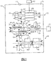
- FIG. 1 shows an integrated drive generator 20. As shown, housing portions 18 and 19 surround the integrated drive generator and a seal plate 17 sits between the housing portions 18 and 19.
- a gas turbine engine 22 may drive an input shaft 23 which selectively drives a disconnect assembly 26.
- the disconnect assembly 26 in turn, drives a carrier shaft 28, which drives a carrier in a gear differential 30.
- a gas turbine engine 22 may drive an input shaft 23 which selectively drives a disconnect assembly 26.
- the disconnect assembly 26 in turn, drives a carrier shaft 28, which drives a carrier in a gear differential 30.
- Gears 38 have a gear interface 42 with a first ring gear portion 40.
- Gears 36 have a gear interface 48 with a second ring gear portion 46.
- Ring gear portion 40 has a gear interface 50 with a main generator drive gear 52.
- drive gear 52 When drive gear 52 is driven to rotate, it rotates a rotor 56 associated with a stator 58 of the main generator as well as an exciter rotor 60. Electric power is generated for a use 62, as known.
- the frequency of the generated electric power be at a desired frequency.
- a gear 15 that is part of the carrier has a gear interface 16 with a gear 13 driving a shaft 14 also within the speed trimmer.
- the speed trimmer 66 includes a variable unit 72 and a fixed unit 76.
- the units 72 and 76 may each be provided with a plurality of pistons and a swash plate arrangement. If the input speed of the gear 13 is too high, the speed of the gear 52 will also be too high, and hence, the speed trimmer 66 acts to lower the speed of the trim gear 46 which will drop the speed of gear 52. On the other hand, if the input speed is too low, the speed trimmer will increase the trim gear speed and he speed seen by gear 52 will increase.
- variable unit 72 receives an input through gear 13 that is proportional to the speed of the input shaft 23.
- the variable unit 72 also receives a control input from a control monitoring the speed of the generator rotor 56.
- the position of the swash plate in the variable unit 72 is changed to in turn change the speed and direction of the fixed unit 76.
- the fixed unit 76 can change the speed, and direction of rotation of the shaft 70, and this then provides control back through the trim ring gear 46 to change the speed reaching the generator.
- the speed trimmer 66 results in the frequency generated by the generator being closer to constant, and at the desired frequency.
- a permanent magnet generator 32 rotates with the ring gear 40.
- An accessory drive shaft 29 rotates with the ring gear 40 and drives a plurality of accessory gears 31.
- the operation of the integrated drive generator 20 is generally as known in the art. A worker of ordinary skill would recognize that the desired frequency and speed at use 62 would dictate a number of design functions.
- Figure 2 shows that there are a pair of hydraulic or speed trimming units 66 associated with a single ring gear 46 and a single carrier 15.
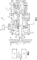
- FIG. 3 shows details of the hydraulic unit 66.
- a speed into the gear 13 will be proportional to the speed from the input shaft 23.
- the gear 13 rotates with a shaft 92.
- the shaft 92 is supported on bearing 93.
- the shaft through splined teeth 121, drives a cylinder block 104 to rotate.
- the shaft 90 is called a fixed block shaft, although it rotates.
- the shaft 90 is supported on a bearing 132 received on a bearing race 130 on the fixed shaft 90.
- an inner race 134 for the bearing 132 is mounted on a housing 19.
- the inner race 134 includes a race surface 136.
- a control 91 changes the position of a swash plate or wobbler 100 based upon the input speed seen at the generator.
- pistons 102 within the cylinder block cam off a surface of the swash plate 100.
- the amount of hydraulic fluid driven by the pistons 102, through a port plate 106, and against piston 110 in a cylinder block 112 changes.
- the pistons 110 move, they cam off a surface of fixed swash plate or wobbler 108. This results in a control of a speed and direction of rotation of cylinder block 112.
- Cylinder block 112 has a spline connection at 121 to a shaft 94.
- the hydraulic unit 66 results in a desired speed and direction of rotation of the shaft 94, ultimately based upon the input speed seen at the generator.
- the shaft 94 drives the shaft 90 through spline connection 137 to in turn drive the gear 68.
- the gear 68 interacts with the trim ring gear 46 such that the ultimate speed leaving the differential 30 to the gear 52 is controlled to achieve a constant desired speed at the generator.
- the cylinder blocks 104 and 112 are effectively identical. In addition, there are similar cylinder blocks 104/112 in both of the hydraulic units 66.
- Figure 4 shows details of the interconnection of the two hydraulic units 66. While it was stated that the components in the two hydraulic units are generally the same, there are certain differences.
- the port plates 106 in the two hydraulic units include one port 106 that includes a bracket mount 150 for receiving a hydraulic cylinder 152.
- Hydraulic cylinder 152 includes a piston 154, which is driven to pivot a lever 157 which cause pivot shaft portions 158 on the variable wobbler plates 100 to rotate some amount and, thus, change the orientation of the cam surfaces on the variable wobbler plates 100.
- a control 156 communicates fluid into the cylinder 152 such that the variable wobbler plates 100 are positioned to provide relatively constant speed to the generator.
- Control 156 may be a governor, such as a mechanical flyball governor.
- a rotating spool valve has a spool position controlled by centrifugal force.
- the control may be provided by flyweights rotating about a spool centerline and against a control spring.
- the shafts 158 on the two wobbler plates 100 extend in opposed directions from cam surfaces on the wobbler plates 100. That is, when the hydraulic units 66 are assembled, the two shaft portions extend towards each other. This is another example of how components in the two units differ.
- Figure 5A shows a first embodiment port plate 200 having a body 201. It should be understood that the port plate 200 would be utilized with one of the hydraulic units and a port plate 220 as shown in Figure 6A would be utilized with the other hydraulic unit. Semi-cylindrical ports 202 and 203 are illustrated, and diametrically opposed to each other.
- Port 203 is a charge port and communicates hydraulic fluid from the fixed wobbler plate side back to the variable wobbler plate side.
- Port 202 is a working fluid port and communicates the fluid from the variable wobbler plate side to the fixed wobbler plate side.
- Three smaller ports 204 are associated with the working fluid port 202.
- Two smaller ports 206A and 206B are associated with the charge port 203.
- the port 202 extends between circumferential ends 197 and 199.
- the port 203 extends between circumferential ends 193 and 195.
- a center plane X can be defined as extending midway, or equidistance, between ends 199 and 193 and ends 195 and 197 and through a center C of a bore 191.
- An angle A is defined from the plane X to a line 207 extending from a center point C and through an end point 208 of the port 206A. In one embodiment, angle A is 22.5 degrees. In embodiments, angle A is between 15 and 25 degrees.
- Figure 5B illustrates a shutdown drainage port that will be at a vertically lowermost location when the port plate 200 is mounted within an integrated drive generator.
- a pair of drain passages 210 extend from an inner end 209 and extend laterally inwardly from an outer side 211 until meeting at a drainage extending passage 212.
- Passage 212 drains oil that collects at the inner diameter of the cylinder block during operation.
- Figure 5C shows a side view of the body 201 of port plate 200.
- Figure 5D is a cross-sectional view along line D-D of Figure 5C .
- the smaller port 206A communicates with a passage 215 leading to the charge pump.
- An angle F is defined bisecting passage 215 and between a line 217 which extends perpendicularly to the plane X. In one embodiment, angle F is 30.3 degrees.
- An angle E is defined between the plane X and a line 219 passing through a center of the passage 214 communicating with smaller port 206B.
- angle A is between 15 and 25 degrees
- angle F is between 25 and 35 degrees
- angle E is between 23 and 33 degrees. In one embodiment, angle E is 27.7 degrees.
- Figure 6A shows a second port plate 220 in a similar view to Figure 5A .
- Ports 222 and 226 function in a manner similar to the Figure 5A embodiment as do the three smaller ports 224 and the two smaller ports 228A and 228B.
- the center axis C is also the center of a bore 221.
- the end point 230 of the smaller ports 228A is also spaced by the same angle as angle A in Figure 5A .
- there is an extension 232 that provides a mount hole 234 to mount the cylinder as shown in Figure 4 . Hole 234 is centered on a point Z.
- Point Z is spaced from the center point C of the bore 221 and along a direction perpendicular to the axis X by a distance d 1 .
- d 1 was 2.994 inches (7.605 centimeters).
- the center point Z is also spaced from center point C by a distance d 2 along the plane X.
- d 2 was 1.659 inches (4.214 centimeters).
- a ratio of d 1 to d 2 was between 1.70 and 1.90.
- Figure 6B is a cross-sectional view showing further details and, in particular, a channel 240 connecting the smaller port 228B to the opening 234.
- the channel 240 is spaced by an angle D from plane X.
- angle D was 34.6 degrees.
- angle D is between 30 and 40.
- a method of replacing a port plate in an integrated drive generator includes the steps of removing an existing port plate from an integrated drive generator having an input shaft connected to a differential.
- the differential is connected to a generator, and to a hydraulic unit.
- the hydraulic unit includes the existing variable wobbler plate and a fixed wobbler plate.
- Each of the wobbler plates are associated with a set of pistons.
- a fixed shaft is associated with the fixed wobbler plate, and connected to rotate by a cylinder block associated with the fixed wobbler plat.
- the fixed shaft includes a spline connection to drive a fixed block shaft.
- the fixed block shaft has gear teeth engaged to a ring gear in the differential.
- the existing port plate is positioned between the pistons associated with the fixed wobbler plate and the pistons associated with the variable wobbler plate.
- the existing port plate is replaced with a replacement port plate having a body defining a semi-cylindrical charge port communicates with two circumferentially smaller charge port portions, and a diametrically opposed working pressure port having three smaller working pressure ports.
- a center plane is defined extending through a center axis of a bore within the body, and equidistance between circumferential ends of the charge port and the working fluid port.
- a first angle is defined between the plane and a circumferential end of the smaller charge port. The first angle is between 15 and 25 degrees.
Landscapes
- Engineering & Computer Science (AREA)
- General Engineering & Computer Science (AREA)
- Mechanical Engineering (AREA)
- Chemical & Material Sciences (AREA)
- Combustion & Propulsion (AREA)
- Hydraulic Motors (AREA)
- Reciprocating Pumps (AREA)
Claims (15)
- Anschlussplatte (200) zur Verwendung in einem integrierten Antriebsgenerator (20), umfassend:einen Körper (201), der einen halbzylindrischen Ladeanschluss ausbildet, der mit zwei in Umfangsrichtung kleineren Ladeanschlussabschnitten in Verbindung steht, und einen diametral gegenüberliegenden Arbeitsdruckanschluss mit drei kleineren Arbeitsdruckanschlüssen und einer definierten Mittelebene, die sich durch eine Bohrungsmittelachse einer darin befindlichen Bohrung erstreckt wobei der erwähnte Körper (201) und der gleiche Abstand zwischen Umfangsenden des erwähnten Ladeanschlusses und des erwähnten Arbeitsfluidanschlusses und einem ersten Winkel, der zwischen der erwähnten Ebene und einem Umfangsende eines der erwähnten kleineren Ladeanschlüsse ausgebildet ist, und der erste erwähnte Winkel zwischen 15 und 25 Grad liegt, und dadurch gekennzeichnet, dassein Drainageanschluss entlang der erwähnten Mittelebene ausgebildet ist und der erwähnte Drainageanschluss ein Paar Durchgänge (210) einschließt, die sich von einer Innenfläche des erwähnten Körpers (201) erstrecken und seitliche Außenseiten des erwähnten Körpers (201), die sich seitlich nach Innen erstrecken, um sich an einem sich verlängernden Durchgang (212) zu treffen.
- Anschlussplatte nach Anspruch 1, wobei ein zweiter Winkel zwischen der erwähnten Mittelebene und einem ersten Kanal ausgebildet ist, der einen der erwähnten kleineren Ladeanschlüsse verbindet, wobei der erwähnte zweite Winkel zwischen 25 und 35 Grad liegt und vorzugsweise
wobei ein dritter Winkel zwischen einem zweiten Kanal, der mit einem zweiten der erwähnten kleineren Ladeanschlüsse in Verbindung steht, und zwischen einer Linie, die den erwähnten zweiten Kanal halbiert, und einer zweiten Linie, die sich von dem erwähnten Mittelpunkt senkrecht zu der Mittelebene erstreckt, ausgebildet ist, wobei der erwähnte dritte Winkel zwischen 23 und 33 Grad liegt. - Anschlussplatte nach einem der vorhergehenden Ansprüche, wobei die erwähnte Anschlussplatte (200) eine Verlängerung aufweist, um ein Montageloch zum Montieren eines Steuerzylinders einzuschließen.
- Anschlussplatte nach Anspruch 3, wobei ein vierter Winkel zwischen der erwähnten Mittelebene und einem dritten Kanal ausgebildet ist, der einen zweiten der erwähnten kleineren Ladeanschlüsse mit dem Montageloch verbindet, und der dritte Winkel zwischen 30 und 40 Grad beträgt.
- Anschlussplatte nach Anspruch 3, wobei das erwähnte Montageloch auf einer Lochmittelachse zentriert ist und die erwähnte Lochmittelachse von der Bohrungsmittelachse um einen ersten Abstand in einer Richtung beabstandet ist, die sich von der erwähnten Bohrungsmittelachse senkrecht zu der erwähnten Mittelebene erstreckt, und um einen zweiten Abstand in eine Richtung beabstandet ist, die sich entlang der erwähnten Mittelebene erstreckt, wobei ein Verhältnis des erwähnten ersten Abstands zum zweiten Abstand zwischen 1,70 und 1,90 liegt.
- Integrierter Antriebsgenerator (20), umfassend:eine Eingangswelle (23), die mit einem Differential verbunden ist, wobei das erwähnte Differential mit einem Generator verbunden ist und das erwähnte Differential auch mit einer Hydraulikeinheit verbunden ist, wobei die erwähnte Hydraulikeinheit eine variable Taumelplatte und eine feste Taumelplatte einschließt und jede der erwähnten Taumelplatten mit einem Satz von Kolben verbunden ist, und eine feste Welle, die mit der erwähnten Platte mit fester Welle assoziiert ist und so angeschlossen ist, dass sie sich mit einem Zylinderblock dreht, der mit der erwähnten festen Taumelplatte assoziiert ist, und die erwähnte feste Welle eine Keilverbindung zum Antrieb einer festen Blockwelle einschließt, wobei die erwähnte feste Blockwelle eine Verzahnung aufweist, die mit einem Zahnkranz in dem erwähnten Differential in Eingriff steht, wobei sich eine Anschlussplatte zwischen den Kolben befindet, die mit der festen Taumelplatte assoziiert sind, und den Kolben, die mit der variablen Taumelplatte assoziiert sind; unddie erwähnte Anschlussplatte nach Anspruch 1.
- Integrierter Antriebsgenerator nach Anspruch 6, wobei der erwähnte Drainageanschluss entlang der erwähnten Ebene ausgebildet ist und der erwähnte Drainageanschluss das erwähnte Paar von Durchgängen einschließt, die sich von einer Innenfläche des erwähnten Körpers (201) erstrecken und seitliche Außenseiten des erwähnten Körpers (201), die sich seitlich nach Innen erstrecken, um sich an einem sich verlängernden Durchgang zu treffen.
- Integrierter Antriebsgenerator nach Anspruch 7, wobei ein zweiter Winkel zwischen der erwähnten Mittelebene und einem ersten Kanal ausgebildet ist, der einen der erwähnten kleineren Ladeanschlüsse verbindet, wobei der erwähnte zweite Winkel zwischen 25 und 35 Grad liegt.
- Integrierter Antriebsgenerator nach Anspruch 8, wobei ein dritter Winkel zwischen einem zweiten Kanal, der mit einem zweiten der erwähnten kleineren Ladeanschlüsse in Verbindung steht, und zwischen einer Linie, die den erwähnten zweiten Kanal halbiert, und einer zweiten Linie, die sich von dem erwähnten Mittelpunkt senkrecht zu der erwähnten Mittelebene erstreckt, ausgebildet ist, wobei der erwähnte dritte Winkel zwischen 23 und 33 Grad liegt.
- Integrierter Antriebsgenerator nach einem der Ansprüche 6 bis 9, wobei die erwähnte Anschlussplatte (200) eine Verlängerung aufweist, um ein Montageloch zum Montieren eines Steuerzylinders einzuschließen.
- Integrierter Antriebsgenerator nach Anspruch 10, wobei ein vierter Winkel zwischen der erwähnten Mittelebene und einem dritten Kanal ausgebildet ist, der den erwähnten zweiten von kleineren Ladeanschlüsse mit dem erwähnten Montageloch verbindet, und der erwähnte dritte Winkel zwischen 30 und 40 Grad beträgt und/oder
wobei das erwähnte Montageloch auf einer Lochmittelachse zentriert ist und die erwähnte Lochmittelachse von der erwähnten Bohrungsmittelachse um einen ersten Abstand in einer Richtung beabstandet ist, die sich von der erwähnten Bohrungsmittelachse senkrecht zu der erwähnten Mittelebene erstreckt, und um einen zweiten Abstand in eine Richtung beabstandet ist, die sich entlang der erwähnte Mittelebene erstreckt, wobei ein Verhältnis des erwähnten ersten Abstands zum zweiten Abstand zwischen 1,70 und 1,90 liegt. - Verfahren zum Ersetzen einer Anschlussplatte (200) in einem integrierten Antriebsgenerator (20), umfassend die Schritte:a) Entfernen einer bestehenden Anschlussplatte von einem integrierten Antriebsgenerator mit einer mit einem Differential verbundenen Eingangswelle, wobei das erwähnte Differential mit einem Generator verbunden ist und das erwähnte Differential auch mit einer Hydraulikeinheit verbunden ist, wobei die erwähnte Hydraulikeinheit die erwähnte bestehende variable Taumelplatte und eine feste Taumelplatte einschließt und jede der erwähnten Taumelplatten mit einem Satz von Kolben assoziiert ist, und eine feste Welle, die mit der erwähnten festen Taumelplatte assoziiert ist und so angeschlossen ist, dass sie sich durch einen Zylinderblock dreht, der mit der erwähnten festen Taumelplatte verbunden ist, und die erwähnte feste Welle eine Keilverbindung zum Antrieb einer festen Blockwelle einschließt, wobei die erwähnte feste Blockwelle eine Verzahnung aufweist, die mit einem Zahnkranz in dem erwähnten Differential in Eingriff steht, wobei die erwähnte bestehende Anschlussplatte zwischen den erwähnten Kolben angebracht ist, die mit der erwähnten festen Taumelplatte assoziiert sind, und den erwähnte Kolben, die mit der erwähnten variablen Taumelplatte assoziiert sind; undb) Ersetzen der bestehenden Anschlussplatte durch eine Ersatzanschlussplatte mit einem Körper, der einen halbzylindrischen Ladeanschluss ausbildet, der mit zwei in Umfangsrichtung kleineren Ladeanschlussabschnitten in Verbindung steht, und einen diametral gegenüberliegenden Arbeitsdruckanschluss mit drei kleineren Arbeitsdruckanschlüssen und einer Mittelebene, die sich durch eine Mittelachse einer darin befindlichen Bohrung erstreckend ausgebildet ist wobei der erwähnte Körper (201) und der gleiche Abstand zwischen Umfangsenden des erwähnten Ladeanschlusses und des erwähnten Arbeitsfluidanschlusses und einem ersten Winkel, der zwischen der erwähnten Ebene und einem Umfangsende des erwähnten kleineren Ladeanschlusses ausgebildet ist, und der erwähnte erste Winkel zwischen 15 und 25 Grad liegt, und dadurch gekennzeichnet, dass
ein Drainageanschluss entlang der erwähnten Mittelebene ausgebildet ist und der erwähnte Drainageanschluss ein Paar Durchgänge einschließt, die sich von einer Innenfläche des erwähnten Körpers erstrecken und seitliche Außenseiten des erwähnten Körpers, die sich seitlich nach Innen erstrecken, um sich an einem Drainagedurchgang zu treffen. - Verfahren zum Ersetzen einer Anschlussplatte nach Anspruch 12, wobei ein zweiter Winkel zwischen der erwähnten Mittelebene und einem ersten Kanal ausgebildet ist, der einen erwähnten der erwähnten kleineren Ladeanschlüsse verbindet, wobei der erwähnte zweite Winkel zwischen 20 und 30 Grad liegt und/oder
wobei ein dritter Winkel zwischen einem zweiten Kanal, der mit einem zweiten der erwähnten kleineren Ladeanschlüsse in Verbindung steht, und zwischen einer Linie, die den erwähnten zweiten Kanal halbiert, und einer zweiten Linie, die sich von dem erwähnten Mittelpunkt senkrecht zu der Mittelebene erstreckt, ausgebildet ist, wobei der erwähnte dritte Winkel zwischen 23 und 33 Grad liegt. - Verfahren zum Ersetzen einer Anschlussplatte nach Anspruch 12 oder 13, wobei die erwähnte Anschlussplatte eine Verlängerung aufweist, um ein Montageloch zum Montieren eines Steuerzylinders einzuschließen, und ein vierter Winkel zwischen der erwähnten Mittelebene und einem dritten Kanal ausgebildet ist, der einen zweiten der erwähnten kleineren Ladeanschlüsse mit dem erwähnten Montageloch verbindet, und der dritte Winkel zwischen 30 und 40 Grad beträgt.
- Verfahren zum Ersetzen einer Anschlussplatte nach Anspruch 14, wobei das erwähnte Montageloch auf einer Lochmittelachse zentriert ist und die erwähnte Lochmittelachse von der Bohrungsmittelachse um einen ersten Abstand in einer Richtung beabstandet ist, die sich von der erwähnten Bohrungsmittelachse senkrecht zu der erwähnten Mittelebene erstreckt, und um einen zweiten Abstand in eine Richtung beabstandet ist, die sich entlang der erwähnten Mittelebene erstreckt, wobei ein Verhältnis des erwähnten ersten Abstands zum zweiten Abstand zwischen 1,70 und 1,90 liegt.
Applications Claiming Priority (1)
| Application Number | Priority Date | Filing Date | Title |
|---|---|---|---|
| US15/874,834 US11002258B2 (en) | 2018-01-18 | 2018-01-18 | Port plate for integrated drive generator |
Publications (2)
| Publication Number | Publication Date |
|---|---|
| EP3514351A1 EP3514351A1 (de) | 2019-07-24 |
| EP3514351B1 true EP3514351B1 (de) | 2022-03-30 |
Family
ID=65036640
Family Applications (1)
| Application Number | Title | Priority Date | Filing Date |
|---|---|---|---|
| EP19152229.1A Active EP3514351B1 (de) | 2018-01-18 | 2019-01-17 | Anschlussplatte für einen integrierten antriebsgenerator |
Country Status (2)
| Country | Link |
|---|---|
| US (1) | US11002258B2 (de) |
| EP (1) | EP3514351B1 (de) |
Families Citing this family (2)
| Publication number | Priority date | Publication date | Assignee | Title |
|---|---|---|---|---|
| FR3104640B1 (fr) * | 2019-12-13 | 2021-12-10 | Safran Aircraft Engines | Platine d’équipements hydrauliques de turbomachine aéronautique |
| US12498036B2 (en) | 2023-03-02 | 2025-12-16 | Hamilton Sundstrand Corporation | IDG governor rotating sleeve |
Family Cites Families (5)
| Publication number | Priority date | Publication date | Assignee | Title |
|---|---|---|---|---|
| US5014513A (en) | 1989-08-30 | 1991-05-14 | Sundstrand Corporation | Self-sealing transfer tube for port plate |
| US7472547B2 (en) | 2006-10-26 | 2009-01-06 | Hamilton Sundstrand Corporation | Hydraulic differential for integrated drive generator |
| EP2636872B1 (de) | 2012-03-05 | 2019-05-01 | Hamilton Sundstrand Corporation | Antriebsanordnung einer Turbomaschine |
| US9115794B2 (en) | 2012-07-06 | 2015-08-25 | Hamilton Sundstrand Corporation | Integrated drive generator pump plate |
| US9845679B2 (en) * | 2015-03-18 | 2017-12-19 | Hamilton Sundstrand Corporation | Port plate assembly for hydraulic unit |
-
2018
- 2018-01-18 US US15/874,834 patent/US11002258B2/en active Active
-
2019
- 2019-01-17 EP EP19152229.1A patent/EP3514351B1/de active Active
Also Published As
| Publication number | Publication date |
|---|---|
| US11002258B2 (en) | 2021-05-11 |
| EP3514351A1 (de) | 2019-07-24 |
| US20190219041A1 (en) | 2019-07-18 |
Similar Documents
| Publication | Publication Date | Title |
|---|---|---|
| EP3514351B1 (de) | Anschlussplatte für einen integrierten antriebsgenerator | |
| EP3514398B1 (de) | Innerer lagerring einer festen blockwelle für einen integrierten antriebsgenerator | |
| EP3483443B1 (de) | Pumpenhülse für einen integrierten antriebsgenerator | |
| EP3511594B1 (de) | Feste blockwelle für einen integrierten antriebsgenerator | |
| EP3511521B1 (de) | Pumpenhülse für eine ladungs- und absaugpumpe eines integrierten antriebsgenerators | |
| US20190203647A1 (en) | Input shaft for use in integrated drive generator | |
| EP3514377B1 (de) | Variable wobblerplatte für integrierten antriebsgenerator | |
| EP3514324B1 (de) | Nockenlaufbuchse für integrierten antriebsgenerator | |
| US10422324B2 (en) | Wear ring for integrated drive generator | |
| EP3511595B1 (de) | Variable blockwelle für einen integrierten antriebsgenerator | |
| EP3473896B1 (de) | Dichtungsplatte zwischen zwei gehäuseabschnitten in einem integrierten antriebsgenerator | |
| EP3508757B1 (de) | Integrierter antriebsgenerator und entsprechendes verfahren zum ersetzen eines reglergetriebes in einem solchen generator | |
| EP3502514B1 (de) | Abgangszahnkranz für integrierten antriebsgenerator | |
| EP3467305B1 (de) | Hydraulikaggregatzylinderblock für integrierten antriebsgenerator |
Legal Events
| Date | Code | Title | Description |
|---|---|---|---|
| PUAI | Public reference made under article 153(3) epc to a published international application that has entered the european phase |
Free format text: ORIGINAL CODE: 0009012 |
|
| STAA | Information on the status of an ep patent application or granted ep patent |
Free format text: STATUS: THE APPLICATION HAS BEEN PUBLISHED |
|
| AK | Designated contracting states |
Kind code of ref document: A1 Designated state(s): AL AT BE BG CH CY CZ DE DK EE ES FI FR GB GR HR HU IE IS IT LI LT LU LV MC MK MT NL NO PL PT RO RS SE SI SK SM TR |
|
| AX | Request for extension of the european patent |
Extension state: BA ME |
|
| STAA | Information on the status of an ep patent application or granted ep patent |
Free format text: STATUS: REQUEST FOR EXAMINATION WAS MADE |
|
| 17P | Request for examination filed |
Effective date: 20191126 |
|
| RBV | Designated contracting states (corrected) |
Designated state(s): AL AT BE BG CH CY CZ DE DK EE ES FI FR GB GR HR HU IE IS IT LI LT LU LV MC MK MT NL NO PL PT RO RS SE SI SK SM TR |
|
| GRAP | Despatch of communication of intention to grant a patent |
Free format text: ORIGINAL CODE: EPIDOSNIGR1 |
|
| STAA | Information on the status of an ep patent application or granted ep patent |
Free format text: STATUS: GRANT OF PATENT IS INTENDED |
|
| INTG | Intention to grant announced |
Effective date: 20211118 |
|
| GRAS | Grant fee paid |
Free format text: ORIGINAL CODE: EPIDOSNIGR3 |
|
| GRAA | (expected) grant |
Free format text: ORIGINAL CODE: 0009210 |
|
| STAA | Information on the status of an ep patent application or granted ep patent |
Free format text: STATUS: THE PATENT HAS BEEN GRANTED |
|
| AK | Designated contracting states |
Kind code of ref document: B1 Designated state(s): AL AT BE BG CH CY CZ DE DK EE ES FI FR GB GR HR HU IE IS IT LI LT LU LV MC MK MT NL NO PL PT RO RS SE SI SK SM TR |
|
| REG | Reference to a national code |
Ref country code: GB Ref legal event code: FG4D |
|
| REG | Reference to a national code |
Ref country code: CH Ref legal event code: EP |
|
| REG | Reference to a national code |
Ref country code: DE Ref legal event code: R096 Ref document number: 602019012907 Country of ref document: DE |
|
| REG | Reference to a national code |
Ref country code: AT Ref legal event code: REF Ref document number: 1479401 Country of ref document: AT Kind code of ref document: T Effective date: 20220415 |
|
| REG | Reference to a national code |
Ref country code: IE Ref legal event code: FG4D |
|
| REG | Reference to a national code |
Ref country code: LT Ref legal event code: MG9D |
|
| PG25 | Lapsed in a contracting state [announced via postgrant information from national office to epo] |
Ref country code: SE Free format text: LAPSE BECAUSE OF FAILURE TO SUBMIT A TRANSLATION OF THE DESCRIPTION OR TO PAY THE FEE WITHIN THE PRESCRIBED TIME-LIMIT Effective date: 20220330 Ref country code: RS Free format text: LAPSE BECAUSE OF FAILURE TO SUBMIT A TRANSLATION OF THE DESCRIPTION OR TO PAY THE FEE WITHIN THE PRESCRIBED TIME-LIMIT Effective date: 20220330 Ref country code: NO Free format text: LAPSE BECAUSE OF FAILURE TO SUBMIT A TRANSLATION OF THE DESCRIPTION OR TO PAY THE FEE WITHIN THE PRESCRIBED TIME-LIMIT Effective date: 20220630 Ref country code: LT Free format text: LAPSE BECAUSE OF FAILURE TO SUBMIT A TRANSLATION OF THE DESCRIPTION OR TO PAY THE FEE WITHIN THE PRESCRIBED TIME-LIMIT Effective date: 20220330 Ref country code: HR Free format text: LAPSE BECAUSE OF FAILURE TO SUBMIT A TRANSLATION OF THE DESCRIPTION OR TO PAY THE FEE WITHIN THE PRESCRIBED TIME-LIMIT Effective date: 20220330 Ref country code: BG Free format text: LAPSE BECAUSE OF FAILURE TO SUBMIT A TRANSLATION OF THE DESCRIPTION OR TO PAY THE FEE WITHIN THE PRESCRIBED TIME-LIMIT Effective date: 20220630 |
|
| REG | Reference to a national code |
Ref country code: NL Ref legal event code: MP Effective date: 20220330 |
|
| REG | Reference to a national code |
Ref country code: AT Ref legal event code: MK05 Ref document number: 1479401 Country of ref document: AT Kind code of ref document: T Effective date: 20220330 |
|
| PG25 | Lapsed in a contracting state [announced via postgrant information from national office to epo] |
Ref country code: LV Free format text: LAPSE BECAUSE OF FAILURE TO SUBMIT A TRANSLATION OF THE DESCRIPTION OR TO PAY THE FEE WITHIN THE PRESCRIBED TIME-LIMIT Effective date: 20220330 Ref country code: GR Free format text: LAPSE BECAUSE OF FAILURE TO SUBMIT A TRANSLATION OF THE DESCRIPTION OR TO PAY THE FEE WITHIN THE PRESCRIBED TIME-LIMIT Effective date: 20220701 Ref country code: FI Free format text: LAPSE BECAUSE OF FAILURE TO SUBMIT A TRANSLATION OF THE DESCRIPTION OR TO PAY THE FEE WITHIN THE PRESCRIBED TIME-LIMIT Effective date: 20220330 |
|
| PG25 | Lapsed in a contracting state [announced via postgrant information from national office to epo] |
Ref country code: NL Free format text: LAPSE BECAUSE OF FAILURE TO SUBMIT A TRANSLATION OF THE DESCRIPTION OR TO PAY THE FEE WITHIN THE PRESCRIBED TIME-LIMIT Effective date: 20220330 |
|
| PG25 | Lapsed in a contracting state [announced via postgrant information from national office to epo] |
Ref country code: SM Free format text: LAPSE BECAUSE OF FAILURE TO SUBMIT A TRANSLATION OF THE DESCRIPTION OR TO PAY THE FEE WITHIN THE PRESCRIBED TIME-LIMIT Effective date: 20220330 Ref country code: SK Free format text: LAPSE BECAUSE OF FAILURE TO SUBMIT A TRANSLATION OF THE DESCRIPTION OR TO PAY THE FEE WITHIN THE PRESCRIBED TIME-LIMIT Effective date: 20220330 Ref country code: RO Free format text: LAPSE BECAUSE OF FAILURE TO SUBMIT A TRANSLATION OF THE DESCRIPTION OR TO PAY THE FEE WITHIN THE PRESCRIBED TIME-LIMIT Effective date: 20220330 Ref country code: PT Free format text: LAPSE BECAUSE OF FAILURE TO SUBMIT A TRANSLATION OF THE DESCRIPTION OR TO PAY THE FEE WITHIN THE PRESCRIBED TIME-LIMIT Effective date: 20220801 Ref country code: ES Free format text: LAPSE BECAUSE OF FAILURE TO SUBMIT A TRANSLATION OF THE DESCRIPTION OR TO PAY THE FEE WITHIN THE PRESCRIBED TIME-LIMIT Effective date: 20220330 Ref country code: EE Free format text: LAPSE BECAUSE OF FAILURE TO SUBMIT A TRANSLATION OF THE DESCRIPTION OR TO PAY THE FEE WITHIN THE PRESCRIBED TIME-LIMIT Effective date: 20220330 Ref country code: CZ Free format text: LAPSE BECAUSE OF FAILURE TO SUBMIT A TRANSLATION OF THE DESCRIPTION OR TO PAY THE FEE WITHIN THE PRESCRIBED TIME-LIMIT Effective date: 20220330 Ref country code: AT Free format text: LAPSE BECAUSE OF FAILURE TO SUBMIT A TRANSLATION OF THE DESCRIPTION OR TO PAY THE FEE WITHIN THE PRESCRIBED TIME-LIMIT Effective date: 20220330 |
|
| PG25 | Lapsed in a contracting state [announced via postgrant information from national office to epo] |
Ref country code: PL Free format text: LAPSE BECAUSE OF FAILURE TO SUBMIT A TRANSLATION OF THE DESCRIPTION OR TO PAY THE FEE WITHIN THE PRESCRIBED TIME-LIMIT Effective date: 20220330 Ref country code: IS Free format text: LAPSE BECAUSE OF FAILURE TO SUBMIT A TRANSLATION OF THE DESCRIPTION OR TO PAY THE FEE WITHIN THE PRESCRIBED TIME-LIMIT Effective date: 20220730 Ref country code: AL Free format text: LAPSE BECAUSE OF FAILURE TO SUBMIT A TRANSLATION OF THE DESCRIPTION OR TO PAY THE FEE WITHIN THE PRESCRIBED TIME-LIMIT Effective date: 20220330 |
|
| REG | Reference to a national code |
Ref country code: DE Ref legal event code: R097 Ref document number: 602019012907 Country of ref document: DE |
|
| PG25 | Lapsed in a contracting state [announced via postgrant information from national office to epo] |
Ref country code: DK Free format text: LAPSE BECAUSE OF FAILURE TO SUBMIT A TRANSLATION OF THE DESCRIPTION OR TO PAY THE FEE WITHIN THE PRESCRIBED TIME-LIMIT Effective date: 20220330 |
|
| PLBE | No opposition filed within time limit |
Free format text: ORIGINAL CODE: 0009261 |
|
| STAA | Information on the status of an ep patent application or granted ep patent |
Free format text: STATUS: NO OPPOSITION FILED WITHIN TIME LIMIT |
|
| 26N | No opposition filed |
Effective date: 20230103 |
|
| PG25 | Lapsed in a contracting state [announced via postgrant information from national office to epo] |
Ref country code: SI Free format text: LAPSE BECAUSE OF FAILURE TO SUBMIT A TRANSLATION OF THE DESCRIPTION OR TO PAY THE FEE WITHIN THE PRESCRIBED TIME-LIMIT Effective date: 20220330 |
|
| P01 | Opt-out of the competence of the unified patent court (upc) registered |
Effective date: 20230522 |
|
| PG25 | Lapsed in a contracting state [announced via postgrant information from national office to epo] |
Ref country code: IT Free format text: LAPSE BECAUSE OF FAILURE TO SUBMIT A TRANSLATION OF THE DESCRIPTION OR TO PAY THE FEE WITHIN THE PRESCRIBED TIME-LIMIT Effective date: 20220330 |
|
| REG | Reference to a national code |
Ref country code: CH Ref legal event code: PL |
|
| PG25 | Lapsed in a contracting state [announced via postgrant information from national office to epo] |
Ref country code: LU Free format text: LAPSE BECAUSE OF NON-PAYMENT OF DUE FEES Effective date: 20230117 |
|
| REG | Reference to a national code |
Ref country code: BE Ref legal event code: MM Effective date: 20230131 |
|
| PG25 | Lapsed in a contracting state [announced via postgrant information from national office to epo] |
Ref country code: LI Free format text: LAPSE BECAUSE OF NON-PAYMENT OF DUE FEES Effective date: 20230131 Ref country code: CH Free format text: LAPSE BECAUSE OF NON-PAYMENT OF DUE FEES Effective date: 20230131 |
|
| PG25 | Lapsed in a contracting state [announced via postgrant information from national office to epo] |
Ref country code: BE Free format text: LAPSE BECAUSE OF NON-PAYMENT OF DUE FEES Effective date: 20230131 |
|
| PG25 | Lapsed in a contracting state [announced via postgrant information from national office to epo] |
Ref country code: IE Free format text: LAPSE BECAUSE OF NON-PAYMENT OF DUE FEES Effective date: 20230117 |
|
| PG25 | Lapsed in a contracting state [announced via postgrant information from national office to epo] |
Ref country code: MC Free format text: LAPSE BECAUSE OF FAILURE TO SUBMIT A TRANSLATION OF THE DESCRIPTION OR TO PAY THE FEE WITHIN THE PRESCRIBED TIME-LIMIT Effective date: 20220330 |
|
| PG25 | Lapsed in a contracting state [announced via postgrant information from national office to epo] |
Ref country code: MC Free format text: LAPSE BECAUSE OF FAILURE TO SUBMIT A TRANSLATION OF THE DESCRIPTION OR TO PAY THE FEE WITHIN THE PRESCRIBED TIME-LIMIT Effective date: 20220330 |
|
| PG25 | Lapsed in a contracting state [announced via postgrant information from national office to epo] |
Ref country code: CY Free format text: LAPSE BECAUSE OF FAILURE TO SUBMIT A TRANSLATION OF THE DESCRIPTION OR TO PAY THE FEE WITHIN THE PRESCRIBED TIME-LIMIT; INVALID AB INITIO Effective date: 20190117 |
|
| PG25 | Lapsed in a contracting state [announced via postgrant information from national office to epo] |
Ref country code: HU Free format text: LAPSE BECAUSE OF FAILURE TO SUBMIT A TRANSLATION OF THE DESCRIPTION OR TO PAY THE FEE WITHIN THE PRESCRIBED TIME-LIMIT; INVALID AB INITIO Effective date: 20190117 |
|
| PG25 | Lapsed in a contracting state [announced via postgrant information from national office to epo] |
Ref country code: TR Free format text: LAPSE BECAUSE OF FAILURE TO SUBMIT A TRANSLATION OF THE DESCRIPTION OR TO PAY THE FEE WITHIN THE PRESCRIBED TIME-LIMIT Effective date: 20220330 |
|
| PGFP | Annual fee paid to national office [announced via postgrant information from national office to epo] |
Ref country code: GB Payment date: 20251217 Year of fee payment: 8 |
|
| PGFP | Annual fee paid to national office [announced via postgrant information from national office to epo] |
Ref country code: FR Payment date: 20251217 Year of fee payment: 8 |
|
| PGFP | Annual fee paid to national office [announced via postgrant information from national office to epo] |
Ref country code: DE Payment date: 20251217 Year of fee payment: 8 |