EP3514364B1 - Actionneur d'inverseur de poussée avec dispositif d'arrêt - Google Patents
Actionneur d'inverseur de poussée avec dispositif d'arrêt Download PDFInfo
- Publication number
- EP3514364B1 EP3514364B1 EP19154020.2A EP19154020A EP3514364B1 EP 3514364 B1 EP3514364 B1 EP 3514364B1 EP 19154020 A EP19154020 A EP 19154020A EP 3514364 B1 EP3514364 B1 EP 3514364B1
- Authority
- EP
- European Patent Office
- Prior art keywords
- lock
- actuator
- assembly
- thrust reverser
- thrust
- Prior art date
- Legal status (The legal status is an assumption and is not a legal conclusion. Google has not performed a legal analysis and makes no representation as to the accuracy of the status listed.)
- Active
Links
- 230000004044 response Effects 0.000 claims description 3
- 230000000712 assembly Effects 0.000 description 22
- 238000000429 assembly Methods 0.000 description 22
- 238000013461 design Methods 0.000 description 13
- 238000013519 translation Methods 0.000 description 11
- 230000007246 mechanism Effects 0.000 description 10
- 238000000034 method Methods 0.000 description 9
- 230000009471 action Effects 0.000 description 6
- 230000006870 function Effects 0.000 description 4
- 238000012423 maintenance Methods 0.000 description 4
- 230000002441 reversible effect Effects 0.000 description 3
- 239000003112 inhibitor Substances 0.000 description 2
- 238000012545 processing Methods 0.000 description 2
- 230000002123 temporal effect Effects 0.000 description 2
- RZVHIXYEVGDQDX-UHFFFAOYSA-N 9,10-anthraquinone Chemical compound C1=CC=C2C(=O)C3=CC=CC=C3C(=O)C2=C1 RZVHIXYEVGDQDX-UHFFFAOYSA-N 0.000 description 1
- 238000013459 approach Methods 0.000 description 1
- 230000008859 change Effects 0.000 description 1
- 230000000994 depressogenic effect Effects 0.000 description 1
- 230000000694 effects Effects 0.000 description 1
- 238000005516 engineering process Methods 0.000 description 1
- 230000003287 optical effect Effects 0.000 description 1
- 230000003449 preventive effect Effects 0.000 description 1
- 230000008569 process Effects 0.000 description 1
- 238000004904 shortening Methods 0.000 description 1
- 230000001360 synchronised effect Effects 0.000 description 1
Images





Classifications
-
- F—MECHANICAL ENGINEERING; LIGHTING; HEATING; WEAPONS; BLASTING
- F02—COMBUSTION ENGINES; HOT-GAS OR COMBUSTION-PRODUCT ENGINE PLANTS
- F02K—JET-PROPULSION PLANTS
- F02K1/00—Plants characterised by the form or arrangement of the jet pipe or nozzle; Jet pipes or nozzles peculiar thereto
- F02K1/54—Nozzles having means for reversing jet thrust
- F02K1/76—Control or regulation of thrust reversers
- F02K1/766—Control or regulation of thrust reversers with blocking systems or locking devices; Arrangement of locking devices for thrust reversers
-
- B—PERFORMING OPERATIONS; TRANSPORTING
- B64—AIRCRAFT; AVIATION; COSMONAUTICS
- B64C—AEROPLANES; HELICOPTERS
- B64C13/00—Control systems or transmitting systems for actuating flying-control surfaces, lift-increasing flaps, air brakes, or spoilers
- B64C13/24—Transmitting means
- B64C13/26—Transmitting means without power amplification or where power amplification is irrelevant
- B64C13/28—Transmitting means without power amplification or where power amplification is irrelevant mechanical
-
- F—MECHANICAL ENGINEERING; LIGHTING; HEATING; WEAPONS; BLASTING
- F02—COMBUSTION ENGINES; HOT-GAS OR COMBUSTION-PRODUCT ENGINE PLANTS
- F02K—JET-PROPULSION PLANTS
- F02K1/00—Plants characterised by the form or arrangement of the jet pipe or nozzle; Jet pipes or nozzles peculiar thereto
- F02K1/54—Nozzles having means for reversing jet thrust
- F02K1/56—Reversing jet main flow
- F02K1/62—Reversing jet main flow by blocking the rearward discharge by means of flaps
- F02K1/625—Reversing jet main flow by blocking the rearward discharge by means of flaps the aft end of the engine cowling being movable to uncover openings for the reversed flow
-
- F—MECHANICAL ENGINEERING; LIGHTING; HEATING; WEAPONS; BLASTING
- F02—COMBUSTION ENGINES; HOT-GAS OR COMBUSTION-PRODUCT ENGINE PLANTS
- F02K—JET-PROPULSION PLANTS
- F02K1/00—Plants characterised by the form or arrangement of the jet pipe or nozzle; Jet pipes or nozzles peculiar thereto
- F02K1/54—Nozzles having means for reversing jet thrust
- F02K1/76—Control or regulation of thrust reversers
- F02K1/763—Control or regulation of thrust reversers with actuating systems or actuating devices; Arrangement of actuators for thrust reversers
-
- F—MECHANICAL ENGINEERING; LIGHTING; HEATING; WEAPONS; BLASTING
- F16—ENGINEERING ELEMENTS AND UNITS; GENERAL MEASURES FOR PRODUCING AND MAINTAINING EFFECTIVE FUNCTIONING OF MACHINES OR INSTALLATIONS; THERMAL INSULATION IN GENERAL
- F16H—GEARING
- F16H25/00—Gearings comprising primarily only cams, cam-followers and screw-and-nut mechanisms
- F16H25/18—Gearings comprising primarily only cams, cam-followers and screw-and-nut mechanisms for conveying or interconverting oscillating or reciprocating motions
- F16H25/20—Screw mechanisms
- F16H25/2025—Screw mechanisms with means to disengage the nut or screw from their counterpart; Means for connecting screw and nut for stopping reciprocating movement
-
- F—MECHANICAL ENGINEERING; LIGHTING; HEATING; WEAPONS; BLASTING
- F16—ENGINEERING ELEMENTS AND UNITS; GENERAL MEASURES FOR PRODUCING AND MAINTAINING EFFECTIVE FUNCTIONING OF MACHINES OR INSTALLATIONS; THERMAL INSULATION IN GENERAL
- F16H—GEARING
- F16H25/00—Gearings comprising primarily only cams, cam-followers and screw-and-nut mechanisms
- F16H25/18—Gearings comprising primarily only cams, cam-followers and screw-and-nut mechanisms for conveying or interconverting oscillating or reciprocating motions
- F16H25/20—Screw mechanisms
- F16H25/24—Elements essential to such mechanisms, e.g. screws, nuts
- F16H25/2454—Brakes; Rotational locks
-
- F—MECHANICAL ENGINEERING; LIGHTING; HEATING; WEAPONS; BLASTING
- F02—COMBUSTION ENGINES; HOT-GAS OR COMBUSTION-PRODUCT ENGINE PLANTS
- F02K—JET-PROPULSION PLANTS
- F02K1/00—Plants characterised by the form or arrangement of the jet pipe or nozzle; Jet pipes or nozzles peculiar thereto
- F02K1/54—Nozzles having means for reversing jet thrust
- F02K1/76—Control or regulation of thrust reversers
-
- F—MECHANICAL ENGINEERING; LIGHTING; HEATING; WEAPONS; BLASTING
- F16—ENGINEERING ELEMENTS AND UNITS; GENERAL MEASURES FOR PRODUCING AND MAINTAINING EFFECTIVE FUNCTIONING OF MACHINES OR INSTALLATIONS; THERMAL INSULATION IN GENERAL
- F16H—GEARING
- F16H25/00—Gearings comprising primarily only cams, cam-followers and screw-and-nut mechanisms
- F16H25/18—Gearings comprising primarily only cams, cam-followers and screw-and-nut mechanisms for conveying or interconverting oscillating or reciprocating motions
- F16H25/20—Screw mechanisms
- F16H2025/2062—Arrangements for driving the actuator
- F16H2025/209—Arrangements for driving the actuator using worm gears
-
- Y—GENERAL TAGGING OF NEW TECHNOLOGICAL DEVELOPMENTS; GENERAL TAGGING OF CROSS-SECTIONAL TECHNOLOGIES SPANNING OVER SEVERAL SECTIONS OF THE IPC; TECHNICAL SUBJECTS COVERED BY FORMER USPC CROSS-REFERENCE ART COLLECTIONS [XRACs] AND DIGESTS
- Y10—TECHNICAL SUBJECTS COVERED BY FORMER USPC
- Y10T—TECHNICAL SUBJECTS COVERED BY FORMER US CLASSIFICATION
- Y10T403/00—Joints and connections
- Y10T403/32—Articulated members
- Y10T403/32254—Lockable at fixed position
- Y10T403/32467—Telescoping members
- Y10T403/32524—Self-locking
-
- Y—GENERAL TAGGING OF NEW TECHNOLOGICAL DEVELOPMENTS; GENERAL TAGGING OF CROSS-SECTIONAL TECHNOLOGIES SPANNING OVER SEVERAL SECTIONS OF THE IPC; TECHNICAL SUBJECTS COVERED BY FORMER USPC CROSS-REFERENCE ART COLLECTIONS [XRACs] AND DIGESTS
- Y10—TECHNICAL SUBJECTS COVERED BY FORMER USPC
- Y10T—TECHNICAL SUBJECTS COVERED BY FORMER US CLASSIFICATION
- Y10T74/00—Machine element or mechanism
- Y10T74/18—Mechanical movements
- Y10T74/18568—Reciprocating or oscillating to or from alternating rotary
- Y10T74/18576—Reciprocating or oscillating to or from alternating rotary including screw and nut
- Y10T74/18704—Means to selectively lock or retard screw or nut
Definitions
- the present invention relates to a thrust reverser actuation system, and more particularly to an actuator, for a thrust reverser actuator that includes a primary lock.
- jet engines on most aircraft include thrust reversers to enhance the stopping power of the aircraft.
- thrust reversers redirect the rearward thrust of the jet engine to a forward direction to decelerate the aircraft. Because the jet thrust is directed forward, the jet thrust also slows down the aircraft upon landing.
- Thrust reverser designs are commonly known, and the particular design utilized depends, at least in part, on the engine manufacturer, the engine configuration, and the propulsion technology being used. Thrust reverser designs used most prominently with turbofan jet engines fall into three general categories: (1) cascade-type thrust reversers; (2) target-type thrust reversers; and (3) pivot door thrust reversers. Each of these designs employs a different type of moveable thrust reverser component to change the direction of the jet thrust.
- Cascade-type thrust reversers are normally used on high-bypass ratio jet engines. This type of thrust reverser is located on the circumference of the engine's midsection and, when deployed, exposes and redirects air flow through a plurality of cascade vanes.
- the moveable thrust reverser components in the cascade design includes several translating sleeves or cowls (“transcowls”) that are deployed to expose the cascade vanes.
- Target-type reversers also referred to as clamshell reversers, are typically used with low-bypass ratio jet engines.
- Target-type thrust reversers use two doors as the moveable thrust reverser components to block the entire jet thrust coming from the rear of the engine. These doors are mounted on the aft portion of the engine and may form the rear part of the engine nacelle.
- Pivot door thrust reversers may utilize four doors on the engine nacelle as the moveable thrust reverser components. In the deployed position, these doors extend outwardly from the nacelle to redirect the jet thrust.
- thrust reversers are primarily deployed during the landing process to slow the aircraft. Thereafter, when the thrust reversers are no longer needed, they are returned to their original, or stowed, position and are locked.
- the thrust reversers in each of the above-described designs are moved between the stowed and deployed positions by means of actuators.
- actuators may include a locking device to prevent unintended thrust reverser movement. While these locking devices are generally safe, they tend to be complex and heavy for certain applications, and have an envelope that is not compatible with certain applications.
- a thrust reverser actuator locking device that improves upon one or more of the above-noted drawbacks. Namely, a locking device that is not complex or heavy as compared to known locks, and/or does not significantly increase actuator system size and/or weight.
- the present invention satisfies one or more of these needs.
- US2007/220998 discloses an actuator that has an output ram driven to extend and retract by a rotating lead screw.
- the lead screw is coupled with a rotating input shaft via a lost-motion drive sleeve connected with the input shaft by cooperating threads so that rotation of the drive shaft causes both axial and rotational movement of the drive sleeve.
- the ram is locked in its retracted position by several radially-extending locking keys, one end of which engage an extension sleeve fixed with the ram and the other end of which are engaged by a lock sleeve.
- Rotation of the input shaft causes the drive sleeve to move axially and engage the lock sleeve, thereby pulling it to one side and allowing the locking keys to move radially out and disengage the extension sleeve to allow it to extend.
- a thrust reverser system includes one or more actuators each having a locking mechanism that prevents unintended actuator movement, and thus unintended thrust reverser movement.
- Each of the actuators additionally includes a lock inhibitor assembly that engages the lock and prevents it from moving to its locked position until the actuator is moved into a stow position. Upon movement to the stow position, the lock inhibitor assembly disengages the lock, and the lock automatically moves into its locked position.
- JP2005349845 discloses a steer-by-wire system, comprising a ball screw mechanism, capable of reliably turning a steering wheel by an auxiliary motor even when a motor to turn the steering wheel has failed.
- EP1785346 discloses a flight control surface actuator includes a mechanism that enables the actuator translation member to be selectively decoupled from the actuator rotating member.
- the actuator includes an actuation member, a translation member, an extension member, and a locking member.
- the actuation member is adapted to receive a drive force and is configured, in response to the drive force, to rotate and cause the translation member to translate.
- the extension member surrounds at least a portion of the translation member and is configured to be selectively coupled to, and decoupled from, the translation member.
- the locking member surrounds at least a portion of the extension tube and is movable between a lock position, in which the locking member couples the extension member to the translation member, and a release position, in which the locking member decouples the extension member from the translation member.
- an actuator assembly for a thrust reverser according to claim 1 is provided.
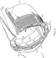
- FIG. 1 a perspective view of portions of an aircraft jet engine fan case 100 that incorporates a cascade-type thrust reverser is depicted.
- the engine fan case 100 includes a pair of semi-circular transcowls 102 that are positioned circumferentially on the outside of the fan case 100, and implement movable thrust reverser components.
- the transcowls 102 cover a plurality of cascade vanes 204, which are positioned between the transcowls 102 and a bypass air flow path 206.
- a series of blocker doors 208 are mechanically linked to the transcowls 102 via a drag link 302 that is rotatably connected to a wall 304 that surrounds the engine case 306. In the stowed position, the blocker doors 208 form a portion of an outer wall 305 and are therefore oriented parallel to a bypass air flow path 206.
- the transcowls 102 When the thrust reversers are commanded to deploy, the transcowls 102 are translated aft, causing the blocker doors 208 to rotate into a deployed position, such that the bypass air flow path 206 is blocked. This also causes the cascade vanes 204 to be exposed and the bypass air flow to be redirected out the cascade vanes 204. The re-direction of the bypass air flow in a forward direction creates a reverse thrust and, thus, works to slow the airplane.
- One or more actuator assemblies 210 per engine are used to operate the transcowls 102.
- the actuator assemblies 210 are mounted to, for example, a stationary torque box 222 and are coupled to the transcowls 102.
- the actuator assemblies 210 are preferably implemented as ballscrew actuators. It is noted that the number and arrangement of actuator assemblies 210 is not limited to what is depicted in FIG. 2 , but could include other numbers of actuator assemblies 210 as well. The number and arrangement of actuators is selected to meet the specific design requirements of the system.
- the actuator assemblies 210 are interconnected via a plurality of drive mechanisms 212, each of which, in the particular depicted example, comprises a flexible shaft.
- the drive mechanisms 212 ensure that the actuator assemblies 210, and thus the transcowls 102, move in a substantially synchronized manner. For example, when one transcowl 102 is moved, another transcowl 102 is moved a like distance at substantially the same time.
- Other drive mechanisms that may be used include gears, or any other mechanism or design that transfers power between the actuator assemblies 210.
- a control system controls movement of the transcowls 102 from a locked and stowed position to an unlocked and deployed position for producing reverse thrust, and returns the transcowls 102 from the deployed position back to the stowed and locked position.
- a simplified functional schematic representation of an exemplary thrust reverser actuation control system is depicted in FIG. 4 .
- the control system 400 includes the actuator assemblies 210, each coupled to a transcowl 102, and interconnected by the drive mechanisms 212.
- Each of actuator assemblies 210 is driven by one or more power sources.
- the one or more power sources may be a hydraulic power source, a pneumatic power source, or an electric power source.
- the power source is electric and, more specifically, is an electric motor 402 that is controlled by a controller circuit 404 and/or a FADEC (full-authority digital engine controller) 406.
- a controller circuit 404 and/or a FADEC (full-authority digital engine controller) 406.
- FADEC full-authority digital engine controller
- one or more of the actuator assemblies 210 includes an integral locking mechanism that prevents unintended movement of the transcowls 102 from the stowed position, and that is automatically relocked upon stowage of the thrust reversers.
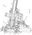
- each of the actuator assemblies 210 includes a drive shaft 502 rotationally mounted within a housing assembly 504 by bearing elements 506, such that the drive shaft 502 rotates about an axis of rotation 501.
- the drive shaft 502 has first 503 and second 505 ends that are adapted to couple the drive shaft 502 to one or more drive mechanisms 212 and/or an electric motor 404 when the actuator assembly 210 is installed in a thrust reverser system.
- the drive shaft 502 includes gearing 510 that meshes with a drive gear 512.
- the drive gear 512 is coupled to one end of a ballscrew shaft 514, which is rotationally supported by a duplex bearing assembly 516.
- a ball nut 518 which is rotationally supported on the ballscrew shaft 514 by a plurality of ball bearing assemblies (not depicted in FIGS. 5 or 6 ), is attached to one of the transcowls 102 (not illustrated in FIGS. 5A-10 ), via an extension tube 522.
- rotation of the drive shaft 502 causes rotation of the ballscrew shaft 514, which results in translation of the ball nut 518, extension tube 522, and the transcowls 102.
- One or more of the actuator assemblies 210 also includes one or more locks 524 (only one depicted) that is rotationally mounted on, or within, the housing assembly 504.
- the lock 524 includes a main body 700 having an actuation end 526 and an engagement end 528.
- the main body 700 is rotationally mounted on the housing assembly 504 between the actuation end 526 and the engagement end 528.
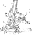
- the main body 700 receives a lock actuation force on the actuation end 526 and is configured, upon receipt thereof, to rotate between a lock position, which is the position depicted in FIGS. 5 , and an unlock position, which is the position depicted in FIG. 6 .
- the lock 524 is configured, when it is in the lock position and the ball nut 518 is in the stowed position, to prevent the ball nut 518 from translating out of the stowed position.
- the lock 524 is additionally configured such that, when it is in the unlock position, it does not prevent the ball nut 518 from translating.
- the actuation end 526 is coupled to a lock actuator 532, and the engagement end 528 selectively engages a portion of the ballnut 518 to prevent translation thereof.
- the lock 524 via the configuration of the lock actuator 532, is biased to the lock position and provides direct, non-electrical, locking of the ballnut 518 when the actuator assembly 210 is moved to the stowed position.
- the lock 524 is moved from the lock position to the unlock position upon energizing the lock actuator 532, which may occur after an over stow command is supplied to release an anti-vibration feature on the lock 524.
- the lock actuator 532 includes a solenoid assembly 534, an actuation rod 536, and a spring 538.
- the solenoid assembly 534 is mounted on the housing assembly 504 and is coupled to the actuation rod 536.
- the actuation rod 536 is in turn coupled to the actuation end 526 of the lock 524.
- the spring 538 biases the solenoid assembly 534, actuation rod 536, and thus the lock 524, toward the lock position (see FIG. 5 ).
- the solenoid assembly 534 When the solenoid assembly 534 is energized, it moves the actuation rod 536 inwardly, which causes the lock 524 to rotate to the unlock position, preferably after an overstow command. Though not depicted in FIGS.
- the solenoid assembly 534 is preferably coupled to receive an input signal of appropriate polarity from external equipment such as, for example, the actuator control system controller circuit 404 or FADEC 406, to move the lock 524 to the unlocked position (see FIG. 6 ).
- the depicted actuator assembly 210 includes only one lock 524, this is merely exemplary of one embodiment. In other embodiments, the actuator assembly 210 may be implemented with two or more locks 524. It may be desirable to use of a plurality of locks 524 in order to more uniformly distribute the load on the ball nut 518 when the locks 524 are in the lock position and the ball nut 518 is in the stowed position.
- redundant position sensors 902 (902-1, 902-2) are mounted on, or at least proximate to, the housing assembly 504 and, in the depicted example, sense the position of portions of the lock 524 that are formed integral with the lock 524 for improved reliability.
- the position sensors 902 which may be one of any numerous sensors known in the art such as, for example, optical sensors, magnetic proximity sensors, or limit switches, each supply an electrical signal to the controller circuit 404 that is representative of the position of the lock 524. In this way, the actuator control system 400 is aware when the lock 524 is in the lock position ( FIG. 5 ) and the unlock position ( FIG. 6 ).
- the actuator assemblies 210 may need to undergo period preventive, and sometimes corrective, maintenance. Many of the procedures associated with these maintenance activities require that the actuator assembly 210 be unlocked, when there is no power available to the solenoid assembly 532. Hence, to accommodate such maintenance procedures, the actuation rod 536 may also be operated manually. The actuation rod 536, when depressed, moves the lock 524 to the unlock position.
- the ballnut 518 When the lock 524 is in the unlock position, the ballnut 518 is free to translate in either the deploy direction or the stow direction, regardless of the position of the ballnut 518. Conversely, when the lock 524 is in the lock position, the ballnut 518 may be prevented from translating in the deploy direction, depending upon the position of the ballnut 518. For example, when the lock 524 is in the lock position and the ballnut 518 is in the stowed position, which are the positions depicted in FIGS. 5 and 6 , the ballnut 518 is prevented from translating in the deploy direction. Alternatively, when the lock 524 is in the lock position and the ballnut 518 is not in the stowed position, the ballnut 518 may translate in either the deploy direction or the stow direction. This latter functionality is provided via tapered surfaces. Specifically, the lock actuation end 526 includes a first tapered surface 542 and the ballnut 518 includes a second tapered surface 544.
- the controller circuit 404 when the actuators are installed in a thrust reverser system, such as the one depicted in FIGS. 1-4 , when the pilot commands the thrust reversers to deploy, the controller circuit 404 will energize the solenoids 532 on each actuator assembly 210 that includes a lock 524. This will cause the actuation rod 536 to translate and move the lock 524 to the unlock position. The controller circuit 404 will then energize the motors 402 to rotate the actuator assemblies 210 in the deploy direction. This rotation will cause the ballnut 518 and extension tube 522 to translate.
- the controller circuit 404 may de-energize the solenoid assemblies 532 after the ballnut 518 and extension tube 522 begin translating, which allows the lock 524 to move back to the lock position.
- the solenoid assemblies 532 remain energized throughout the deploy and stow cycle, and are deenergized after the transcowls are stowed. Actuator assembly rotation, and thus transcowl translation, continues until the cascade vanes 204 are uncovered. As was noted above, when this occurs a reverse thrust is produced to assist in slowing the aircraft.
- the pilot will command the thrust reversers to move to the stowed position.
- the controller circuit 404 will energize the motors 402 to drive the actuator assemblies 210 in the stow direction.
- the tapered surface 544 on the ballnut 518 engages the tapered surface 542 on the lock engagement end 528.
- the ballnut 518 continues translating, it causes the lock 524 to rotate, against the force of the spring 538, toward the unlock position.
- the locks 524 on each actuator assembly 210 having a lock 524 are automatically moved, under the force of the spring 538, to the lock position.
- the disclosed embodiment is not limited to use with a cascade-type thrust reverser system, but can be incorporated into other thrust reverser design types.
- the embodiment is not limited to use with an electric, electromechanical, or hydraulic thrust reverser actuation system.
- the lock can be incorporated into other actuation system designs, including pneumatic and hydraulic designs (see FIG. 10 ).
- the actuator assemblies may be used to move components other than thrust reverser components.
- the actuator assemblies may be used to move flaps, and/or slats.
- the lock 542 may be variously configured.
- the lock 542 is configured as a lock pin that translates between a lock position and an unlock position, which is the depicted position. In the lock position, the lock is partially disposed within a lock pin opening 1102 that is formed in the ball nut 518.
- the lock pin preferably includes a tapered tip and the ball nut 518 preferably includes a tapered ramp.
- the spring-loaded actuator lock is located on the ball screw side of the actuator gearing and provides direct, non-electrical, locking of the ball nut upon actuator retraction to the stow position.
- the lock prevents translation of the ball screw nut.
- the lock is released upon energizing of a linked solenoid.
- the lock is packaged between the actuator gearbox and mounting hardware and thereby dramatically minimizes the envelope needed to package the actuator onto the nacelle.
- the system includes positive feedback to the FADEC that the lock is engaged thru redundant proximity sensors.
- Skilled artisans may implement the described functionality in varying ways for each particular application, but such implementation decisions should not be interpreted as causing a departure from the scope of the present invention.
- an embodiment of a system or a component may employ various integrated circuit components, e.g., memory elements, digital signal processing elements, logic elements, look-up tables, or the like, which may carry out a variety of functions under the control of one or more microprocessors or other control devices.
- integrated circuit components e.g., memory elements, digital signal processing elements, logic elements, look-up tables, or the like, which may carry out a variety of functions under the control of one or more microprocessors or other control devices.
- DSP digital signal processor
- ASIC application specific integrated circuit
- FPGA field programmable gate array
- a general-purpose processor may be a microprocessor, but in the alternative, the processor may be any conventional processor, controller, microcontroller, or state machine.
- a processor may also be implemented as a combination of computing devices, e.g., a combination of a DSP and a microprocessor, a plurality of microprocessors, one or more microprocessors in conjunction with a DSP core, or any other such configuration.
- a software module may reside in RAM memory, flash memory, ROM memory, EPROM memory, EEPROM memory, registers, hard disk, a removable disk, a CD-ROM, or any other form of storage medium known in the art.
- An exemplary storage medium is coupled to the processor such the processor can read information from, and write information to, the storage medium.
- the storage medium may be integral to the processor.
- the processor and the storage medium may reside in an ASIC.
- the ASIC may reside in a user terminal.
- the processor and the storage medium may reside as discrete components in a user terminal
Landscapes
- Engineering & Computer Science (AREA)
- General Engineering & Computer Science (AREA)
- Mechanical Engineering (AREA)
- Chemical & Material Sciences (AREA)
- Combustion & Propulsion (AREA)
- Automation & Control Theory (AREA)
- Aviation & Aerospace Engineering (AREA)
- Transmission Devices (AREA)
- Braking Arrangements (AREA)
Claims (3)
- Ensemble actionneur pour un inverseur de poussée, comprenant :un ensemble logement (504) ;une vis à billes (514) montée en rotation sur et s'étendant depuis l'ensemble logement (504), ladite vis à billes (514) couplée pour recevoir un couple d'entraînement de l'actionneur et conçue, lors de réception de celui-ci, pour tourner ;un écrou à billes (518) supporté en rotation sur la vis à billes (514) et conçu, en réponse à la rotation de la vis à billes (514), pour se déplacer en translation le long de la vis à billes (514) entre une position repliée et une position déployée, ledit écrou à billes (518) comportant une ouverture de goupille de verrouillage (1102) formée à l'intérieur ;un verrou (524) disposé, au moins partiellement, à l'intérieur de l'ensemble logement (504) et conçu pour se déplacer entre une position verrouillée et une position déverrouillée, ledit verrou comprenant une goupille de verrouillage simple adaptée à effectuer une translation entre les positions verrouillée et déverrouillée ;un ensemble solénoïde (534) couplé à la goupille de verrouillage simple et conçu, lorsqu'il est sous tension, pour provoquer la translation de la goupille de verrouillage simple vers la position déverrouillée ; etun ressort (538) couplé à l'ensemble solénoïde (534) et conçu pour fournir une force de sollicitation à l'ensemble solénoïde (534), lequel pousse la goupille de verrouillage simple à effectuer une translation vers la position verrouillée,dans lequel le verrou (524) empêche l'écrou à billes (518) d'effectuer une translation hors de la position repliée lorsque (i) le verrou (524) est en position verrouillée, (ii) l'écrou à billes (518) est en position repliée et (iii) la goupille de verrouillage simple est partiellement disposée à l'intérieur de l'ouverture de goupille de verrouillage (1102).
- Ensemble actionneur selon la revendication 1, dans lequel le verrou (524) n'empêche pas l'écrou à billes (518) d'effectuer une translation lorsque le verrou est en position déverrouillée.
- Ensemble actionneur selon la revendication 1, comprenant en outre :
un capteur de position verrouillée (902) monté sur l'ensemble logement (504) et conçu pour détecter la position verrouillée.
Applications Claiming Priority (3)
| Application Number | Priority Date | Filing Date | Title |
|---|---|---|---|
| US201261622133P | 2012-04-10 | 2012-04-10 | |
| US13/564,444 US9188081B2 (en) | 2012-04-10 | 2012-08-01 | Thrust reverser actuator with primary lock |
| EP13160504.0A EP2650519B1 (fr) | 2012-04-10 | 2013-03-21 | Actionneur d'inverseur de poussée avec dispositif d'arrêt |
Related Parent Applications (2)
| Application Number | Title | Priority Date | Filing Date |
|---|---|---|---|
| EP13160504.0A Division-Into EP2650519B1 (fr) | 2012-04-10 | 2013-03-21 | Actionneur d'inverseur de poussée avec dispositif d'arrêt |
| EP13160504.0A Division EP2650519B1 (fr) | 2012-04-10 | 2013-03-21 | Actionneur d'inverseur de poussée avec dispositif d'arrêt |
Publications (2)
| Publication Number | Publication Date |
|---|---|
| EP3514364A1 EP3514364A1 (fr) | 2019-07-24 |
| EP3514364B1 true EP3514364B1 (fr) | 2020-05-13 |
Family
ID=48040002
Family Applications (2)
| Application Number | Title | Priority Date | Filing Date |
|---|---|---|---|
| EP19154020.2A Active EP3514364B1 (fr) | 2012-04-10 | 2013-03-21 | Actionneur d'inverseur de poussée avec dispositif d'arrêt |
| EP13160504.0A Active EP2650519B1 (fr) | 2012-04-10 | 2013-03-21 | Actionneur d'inverseur de poussée avec dispositif d'arrêt |
Family Applications After (1)
| Application Number | Title | Priority Date | Filing Date |
|---|---|---|---|
| EP13160504.0A Active EP2650519B1 (fr) | 2012-04-10 | 2013-03-21 | Actionneur d'inverseur de poussée avec dispositif d'arrêt |
Country Status (3)
| Country | Link |
|---|---|
| US (2) | US9188081B2 (fr) |
| EP (2) | EP3514364B1 (fr) |
| CN (1) | CN103362688A (fr) |
Families Citing this family (25)
| Publication number | Priority date | Publication date | Assignee | Title |
|---|---|---|---|---|
| JP6047371B2 (ja) * | 2012-10-31 | 2016-12-21 | 株式会社ハイレックスコーポレーション | 開閉駆動装置 |
| FR3003605B1 (fr) * | 2013-03-22 | 2015-04-03 | Sagem Defense Securite | Dispositif d'actionnement pour deplacer un capot mobile d'un inverseur de poussee |
| WO2014196985A1 (fr) * | 2013-06-07 | 2014-12-11 | Ge Aviation Systems Llc | Moteur équipé d'un mécanisme de verrouillage d'inverseur de poussée |
| US10487690B2 (en) * | 2014-08-18 | 2019-11-26 | Rohr, Inc. | Actively controlled cooling air exhaust door on an aircraft engine nacelle |
| EP3193003A1 (fr) * | 2016-01-15 | 2017-07-19 | Goodrich Actuation Systems Ltd. | Architecture de système de commande d'inverseur de poussée |
| US10415504B2 (en) | 2016-02-09 | 2019-09-17 | Honeywell International Inc. | Translating cowl thrust reverser system with over-stow unlocking capability |
| US10054079B2 (en) * | 2016-02-09 | 2018-08-21 | Woodward, Inc. | Thrust reverser actuating |
| US10294893B2 (en) | 2016-05-25 | 2019-05-21 | Honeywell International Inc. | System and method for monitoring a translating cowl thrust reverser |
| DE102016223978A1 (de) | 2016-12-01 | 2018-06-07 | Schaeffler Technologies AG & Co. KG | Spindeltrieb mit Arretierung |
| RU2714658C1 (ru) * | 2016-12-30 | 2020-02-18 | Сафран Электроникс Энд Дифенс | Привод с пассивной блокировкой |
| FR3063522B1 (fr) * | 2017-03-06 | 2021-05-07 | Safran Nacelles | Dispositif d'actionnement d'un inverseur de poussee a organe d'antideploiement |
| FR3063527B1 (fr) * | 2017-03-06 | 2019-04-05 | Safran Electronics & Defense | Verin a verrouillage integre |
| US10724476B2 (en) * | 2017-03-27 | 2020-07-28 | Rohr, Inc. | Locking apparatus for a thrust reverser translating sleeve |
| EP3406888B1 (fr) | 2017-05-22 | 2022-03-23 | Goodrich Actuation Systems Limited | Actionneur |
| US10907577B2 (en) * | 2017-10-23 | 2021-02-02 | Rohr, Inc. | Translating lock for pivot door thrust reverser |
| US10794328B2 (en) * | 2018-07-06 | 2020-10-06 | Rohr, Inc. | Thrust reverser with blocker door folding linkage |
| CN110466796B (zh) * | 2019-07-30 | 2023-02-28 | 中国航发沈阳发动机研究所 | 一种反推力装置手动展开收起装置 |
| US11597508B2 (en) | 2021-05-13 | 2023-03-07 | Beta Air, Llc | Aircraft having reverse thrust capabilities |
| US11512665B2 (en) | 2020-03-20 | 2022-11-29 | The Boeing Company | Locking linear actuator |
| US12486029B2 (en) | 2021-05-13 | 2025-12-02 | Beta Air Llc | Aircraft having reverse thrust capabilities |
| EP4177457A1 (fr) | 2021-11-03 | 2023-05-10 | Goodrich Actuation Systems Limited | Détection de position de verrouillage |
| US11773807B1 (en) * | 2022-05-10 | 2023-10-03 | Honeywell International Inc. | Actuator systems for thrust reverser |
| EP4428353A1 (fr) | 2023-03-06 | 2024-09-11 | Rohr, Inc. | Inverseur de poussée avec liaison pliable de porte de blocage |
| US12565929B2 (en) | 2023-12-18 | 2026-03-03 | Woodward, Inc. | Lock assembly for linear actuators |
| US12331701B1 (en) | 2024-03-11 | 2025-06-17 | Rohr, Inc. | Thrust reverser blocker door with fairing |
Family Cites Families (32)
| Publication number | Priority date | Publication date | Assignee | Title |
|---|---|---|---|---|
| AT280001B (de) * | 1967-10-23 | 1970-03-25 | Deckel Ag Friedrich | Antriebvorrichtung für eine vertikale Kugelrollspindel |
| US4149430A (en) * | 1977-09-26 | 1979-04-17 | The United States Of America As Represented By The Secretary Of The Army | Brake for ball screw |
| US4463661A (en) * | 1982-02-24 | 1984-08-07 | Pneumo Corporation | Fluid actuator with remote lock release assembly |
| US4491059A (en) * | 1982-03-29 | 1985-01-01 | Pneumo Corporation | Fluid actuator with manual lock release and lock position sensor |
| RU2120559C1 (ru) * | 1992-09-21 | 1998-10-20 | Дзе Боинг Компани | Механический стопор для реверсера тяги реактивного двигателя |
| US5826823A (en) | 1996-02-07 | 1998-10-27 | Rohr, Inc. | Actuator and safety lock system for pivoting door thrust reverser for aircraft jet engine |
| FR2755730B1 (fr) * | 1996-11-14 | 1999-01-08 | Hispano Suiza Sa | Systeme de commande electrique pour inverseur de poussee de turboreacteur |
| FR2765916B1 (fr) | 1997-07-10 | 1999-08-20 | Hispano Suiza Sa | Inverseur de poussee a resistance amelioree aux impacts |
| US6129333A (en) | 1998-08-14 | 2000-10-10 | Young & Franklin | Spring locking mechanism |
| US6467363B2 (en) | 2001-02-07 | 2002-10-22 | Moog Inc. | Ball screw actuator locking mechanism |
| US6519929B2 (en) | 2001-04-30 | 2003-02-18 | Honeywell International, Inc. | System and method for controlling the deployment of jet engine thrust reversers |
| US6487846B1 (en) | 2001-09-07 | 2002-12-03 | Honeywell International, Inc. | Thrust reverser actuator including an integrated locking mechanism |
| US6786039B2 (en) * | 2001-09-07 | 2004-09-07 | Honeywell International, Inc. | Thrust reverser actuator with an automatic relock and lock drop prevention mechanism |
| US6935097B2 (en) | 2003-04-17 | 2005-08-30 | Honeywell International, Inc. | Lock assembly that inhibits thrust reverser movement at or near the stowed position |
| JP4466839B2 (ja) * | 2004-06-08 | 2010-05-26 | 株式会社ジェイテクト | ステアバイワイヤシステム |
| JP4650072B2 (ja) * | 2005-04-12 | 2011-03-16 | 富士ゼロックス株式会社 | 質問応答システム、およびデータ検索方法、並びにコンピュータ・プログラム |
| US7610828B2 (en) * | 2005-11-15 | 2009-11-03 | Honeywell International Inc. | Flight control surface actuator assembly including a free trial mechanism |
| GB0604520D0 (en) * | 2006-03-07 | 2006-04-12 | Smiths Group Plc | Actuators |
| US7946105B2 (en) | 2006-11-02 | 2011-05-24 | Honeywell International Inc. | Bi-directional locking ring assembly for aircraft thrust reverser manual drive unit |
| FR2913080B1 (fr) * | 2007-02-22 | 2009-04-03 | Aircelle Sa | Verin a dispositif de verrouillage integre |
| GB0719689D0 (en) | 2007-10-09 | 2007-11-14 | Goodrich Actuation Systems Ltd | Actuator arrangement |
| US8113076B2 (en) | 2008-08-07 | 2012-02-14 | Itt Manufacturing Enterprises, Inc. | Mechanical positioner for reclining seat assembly |
| GB0817775D0 (en) | 2008-09-29 | 2008-11-05 | Goodrich Actuation Systems Ltd | Actuator |
| US8181905B2 (en) | 2008-12-17 | 2012-05-22 | Rohr, Inc. | Aircraft engine nacelle with translating inlet cowl |
| JP5306838B2 (ja) * | 2008-12-26 | 2013-10-02 | ナブテスコ株式会社 | 電動アクチュエータ |
| GB0917065D0 (en) | 2009-09-29 | 2009-11-11 | Goodrich Actuation Systems Ltd | Thrust reverser actuation |
| GB0917057D0 (en) | 2009-09-29 | 2009-11-11 | Goodrich Actuation Systems Ltd | Thrust reverser actuation |
| GB0917059D0 (en) | 2009-09-29 | 2009-11-11 | Goodrich Actuation Systems Ltd | No-back arrangement |
| US8794084B2 (en) * | 2010-03-18 | 2014-08-05 | Parker-Hannifin Corporation | Jam-tolerant electromechanical actuator |
| US8978356B2 (en) * | 2010-12-03 | 2015-03-17 | The Boeing Company | Thrust reverser and variable area fan nozzle actuation system and method |
| US8844389B2 (en) * | 2011-12-14 | 2014-09-30 | Woodward Hrt, Inc. | Automatically locking linear actuator |
| US9086035B2 (en) * | 2012-01-20 | 2015-07-21 | Hamilton Sundstrand Corporation | Integrated thrust reverser actuator and variable area fan nozzle actuator |
-
2012
- 2012-08-01 US US13/564,444 patent/US9188081B2/en active Active
-
2013
- 2013-03-21 EP EP19154020.2A patent/EP3514364B1/fr active Active
- 2013-03-21 EP EP13160504.0A patent/EP2650519B1/fr active Active
- 2013-04-09 CN CN2013101209240A patent/CN103362688A/zh active Pending
-
2015
- 2015-10-27 US US14/923,586 patent/US10330046B2/en active Active
Non-Patent Citations (1)
| Title |
|---|
| None * |
Also Published As
| Publication number | Publication date |
|---|---|
| EP2650519B1 (fr) | 2019-05-08 |
| EP3514364A1 (fr) | 2019-07-24 |
| EP2650519A3 (fr) | 2017-12-06 |
| US20160047334A1 (en) | 2016-02-18 |
| US20130264399A1 (en) | 2013-10-10 |
| EP2650519A2 (fr) | 2013-10-16 |
| US10330046B2 (en) | 2019-06-25 |
| CN103362688A (zh) | 2013-10-23 |
| US9188081B2 (en) | 2015-11-17 |
Similar Documents
| Publication | Publication Date | Title |
|---|---|---|
| EP2650519B1 (fr) | Actionneur d'inverseur de poussée avec dispositif d'arrêt | |
| EP1554484B1 (fr) | Verin d'inversion de poussee a mecanisme automatique de reverrouillage et de prevention du deverrouillage | |
| US6684623B2 (en) | Gearless electric thrust reverser actuators and actuation system incorporating same | |
| EP1386072B1 (fr) | Dispositif de commande de déploiement des inverseurs de poussée d'un turboréacteur | |
| US6935097B2 (en) | Lock assembly that inhibits thrust reverser movement at or near the stowed position | |
| US6598386B2 (en) | Jet engine thrust reverser system having torque limited synchronization | |
| US6487846B1 (en) | Thrust reverser actuator including an integrated locking mechanism | |
| EP3205867B1 (fr) | Système inverseur de poussée à capot mobile en translation avec capacité de déverrouillage en sur-arrimage | |
| CN105074187B (zh) | 用于使推力反向器的可动盖运动的致动装置 | |
| US20050001095A1 (en) | Self-aligning thrust reverser system lock assembly | |
| US10393066B2 (en) | Aircraft thrust reverser with out-of-plane assisting actuator | |
| US20040112040A1 (en) | Thrust reverser system power drive unit with dual sequential torque decoupler and method | |
| US20110296812A1 (en) | Thrust reverser actuation system architecture | |
| EP3287628B1 (fr) | Système inverseur de poussée d'un aéronef avec une voie de charge de poussée inverse | |
| US20240183325A1 (en) | Traveling finger lock for an actuator |
Legal Events
| Date | Code | Title | Description |
|---|---|---|---|
| PUAI | Public reference made under article 153(3) epc to a published international application that has entered the european phase |
Free format text: ORIGINAL CODE: 0009012 |
|
| STAA | Information on the status of an ep patent application or granted ep patent |
Free format text: STATUS: REQUEST FOR EXAMINATION WAS MADE |
|
| 17P | Request for examination filed |
Effective date: 20190128 |
|
| AC | Divisional application: reference to earlier application |
Ref document number: 2650519 Country of ref document: EP Kind code of ref document: P |
|
| AK | Designated contracting states |
Kind code of ref document: A1 Designated state(s): AL AT BE BG CH CY CZ DE DK EE ES FI FR GB GR HR HU IE IS IT LI LT LU LV MC MK MT NL NO PL PT RO RS SE SI SK SM TR |
|
| GRAP | Despatch of communication of intention to grant a patent |
Free format text: ORIGINAL CODE: EPIDOSNIGR1 |
|
| STAA | Information on the status of an ep patent application or granted ep patent |
Free format text: STATUS: GRANT OF PATENT IS INTENDED |
|
| RIC1 | Information provided on ipc code assigned before grant |
Ipc: F02K 1/76 20060101ALI20191218BHEP Ipc: F02K 1/62 20060101AFI20191218BHEP |
|
| INTG | Intention to grant announced |
Effective date: 20200113 |
|
| GRAS | Grant fee paid |
Free format text: ORIGINAL CODE: EPIDOSNIGR3 |
|
| GRAA | (expected) grant |
Free format text: ORIGINAL CODE: 0009210 |
|
| STAA | Information on the status of an ep patent application or granted ep patent |
Free format text: STATUS: THE PATENT HAS BEEN GRANTED |
|
| AC | Divisional application: reference to earlier application |
Ref document number: 2650519 Country of ref document: EP Kind code of ref document: P |
|
| AK | Designated contracting states |
Kind code of ref document: B1 Designated state(s): AL AT BE BG CH CY CZ DE DK EE ES FI FR GB GR HR HU IE IS IT LI LT LU LV MC MK MT NL NO PL PT RO RS SE SI SK SM TR |
|
| REG | Reference to a national code |
Ref country code: GB Ref legal event code: FG4D |
|
| REG | Reference to a national code |
Ref country code: CH Ref legal event code: EP |
|
| REG | Reference to a national code |
Ref country code: DE Ref legal event code: R096 Ref document number: 602013069203 Country of ref document: DE |
|
| REG | Reference to a national code |
Ref country code: AT Ref legal event code: REF Ref document number: 1270607 Country of ref document: AT Kind code of ref document: T Effective date: 20200615 |
|
| REG | Reference to a national code |
Ref country code: LT Ref legal event code: MG4D |
|
| REG | Reference to a national code |
Ref country code: NL Ref legal event code: MP Effective date: 20200513 |
|
| PG25 | Lapsed in a contracting state [announced via postgrant information from national office to epo] |
Ref country code: LT Free format text: LAPSE BECAUSE OF FAILURE TO SUBMIT A TRANSLATION OF THE DESCRIPTION OR TO PAY THE FEE WITHIN THE PRESCRIBED TIME-LIMIT Effective date: 20200513 Ref country code: FI Free format text: LAPSE BECAUSE OF FAILURE TO SUBMIT A TRANSLATION OF THE DESCRIPTION OR TO PAY THE FEE WITHIN THE PRESCRIBED TIME-LIMIT Effective date: 20200513 Ref country code: GR Free format text: LAPSE BECAUSE OF FAILURE TO SUBMIT A TRANSLATION OF THE DESCRIPTION OR TO PAY THE FEE WITHIN THE PRESCRIBED TIME-LIMIT Effective date: 20200814 Ref country code: PT Free format text: LAPSE BECAUSE OF FAILURE TO SUBMIT A TRANSLATION OF THE DESCRIPTION OR TO PAY THE FEE WITHIN THE PRESCRIBED TIME-LIMIT Effective date: 20200914 Ref country code: SE Free format text: LAPSE BECAUSE OF FAILURE TO SUBMIT A TRANSLATION OF THE DESCRIPTION OR TO PAY THE FEE WITHIN THE PRESCRIBED TIME-LIMIT Effective date: 20200513 Ref country code: IS Free format text: LAPSE BECAUSE OF FAILURE TO SUBMIT A TRANSLATION OF THE DESCRIPTION OR TO PAY THE FEE WITHIN THE PRESCRIBED TIME-LIMIT Effective date: 20200913 Ref country code: NO Free format text: LAPSE BECAUSE OF FAILURE TO SUBMIT A TRANSLATION OF THE DESCRIPTION OR TO PAY THE FEE WITHIN THE PRESCRIBED TIME-LIMIT Effective date: 20200813 |
|
| PG25 | Lapsed in a contracting state [announced via postgrant information from national office to epo] |
Ref country code: RS Free format text: LAPSE BECAUSE OF FAILURE TO SUBMIT A TRANSLATION OF THE DESCRIPTION OR TO PAY THE FEE WITHIN THE PRESCRIBED TIME-LIMIT Effective date: 20200513 Ref country code: BG Free format text: LAPSE BECAUSE OF FAILURE TO SUBMIT A TRANSLATION OF THE DESCRIPTION OR TO PAY THE FEE WITHIN THE PRESCRIBED TIME-LIMIT Effective date: 20200813 Ref country code: HR Free format text: LAPSE BECAUSE OF FAILURE TO SUBMIT A TRANSLATION OF THE DESCRIPTION OR TO PAY THE FEE WITHIN THE PRESCRIBED TIME-LIMIT Effective date: 20200513 Ref country code: LV Free format text: LAPSE BECAUSE OF FAILURE TO SUBMIT A TRANSLATION OF THE DESCRIPTION OR TO PAY THE FEE WITHIN THE PRESCRIBED TIME-LIMIT Effective date: 20200513 |
|
| REG | Reference to a national code |
Ref country code: AT Ref legal event code: MK05 Ref document number: 1270607 Country of ref document: AT Kind code of ref document: T Effective date: 20200513 |
|
| PG25 | Lapsed in a contracting state [announced via postgrant information from national office to epo] |
Ref country code: NL Free format text: LAPSE BECAUSE OF FAILURE TO SUBMIT A TRANSLATION OF THE DESCRIPTION OR TO PAY THE FEE WITHIN THE PRESCRIBED TIME-LIMIT Effective date: 20200513 Ref country code: AL Free format text: LAPSE BECAUSE OF FAILURE TO SUBMIT A TRANSLATION OF THE DESCRIPTION OR TO PAY THE FEE WITHIN THE PRESCRIBED TIME-LIMIT Effective date: 20200513 |
|
| PG25 | Lapsed in a contracting state [announced via postgrant information from national office to epo] |
Ref country code: SM Free format text: LAPSE BECAUSE OF FAILURE TO SUBMIT A TRANSLATION OF THE DESCRIPTION OR TO PAY THE FEE WITHIN THE PRESCRIBED TIME-LIMIT Effective date: 20200513 Ref country code: IT Free format text: LAPSE BECAUSE OF FAILURE TO SUBMIT A TRANSLATION OF THE DESCRIPTION OR TO PAY THE FEE WITHIN THE PRESCRIBED TIME-LIMIT Effective date: 20200513 Ref country code: EE Free format text: LAPSE BECAUSE OF FAILURE TO SUBMIT A TRANSLATION OF THE DESCRIPTION OR TO PAY THE FEE WITHIN THE PRESCRIBED TIME-LIMIT Effective date: 20200513 Ref country code: CZ Free format text: LAPSE BECAUSE OF FAILURE TO SUBMIT A TRANSLATION OF THE DESCRIPTION OR TO PAY THE FEE WITHIN THE PRESCRIBED TIME-LIMIT Effective date: 20200513 Ref country code: RO Free format text: LAPSE BECAUSE OF FAILURE TO SUBMIT A TRANSLATION OF THE DESCRIPTION OR TO PAY THE FEE WITHIN THE PRESCRIBED TIME-LIMIT Effective date: 20200513 Ref country code: ES Free format text: LAPSE BECAUSE OF FAILURE TO SUBMIT A TRANSLATION OF THE DESCRIPTION OR TO PAY THE FEE WITHIN THE PRESCRIBED TIME-LIMIT Effective date: 20200513 Ref country code: AT Free format text: LAPSE BECAUSE OF FAILURE TO SUBMIT A TRANSLATION OF THE DESCRIPTION OR TO PAY THE FEE WITHIN THE PRESCRIBED TIME-LIMIT Effective date: 20200513 Ref country code: DK Free format text: LAPSE BECAUSE OF FAILURE TO SUBMIT A TRANSLATION OF THE DESCRIPTION OR TO PAY THE FEE WITHIN THE PRESCRIBED TIME-LIMIT Effective date: 20200513 |
|
| REG | Reference to a national code |
Ref country code: DE Ref legal event code: R097 Ref document number: 602013069203 Country of ref document: DE |
|
| PG25 | Lapsed in a contracting state [announced via postgrant information from national office to epo] |
Ref country code: PL Free format text: LAPSE BECAUSE OF FAILURE TO SUBMIT A TRANSLATION OF THE DESCRIPTION OR TO PAY THE FEE WITHIN THE PRESCRIBED TIME-LIMIT Effective date: 20200513 Ref country code: SK Free format text: LAPSE BECAUSE OF FAILURE TO SUBMIT A TRANSLATION OF THE DESCRIPTION OR TO PAY THE FEE WITHIN THE PRESCRIBED TIME-LIMIT Effective date: 20200513 |
|
| PLBE | No opposition filed within time limit |
Free format text: ORIGINAL CODE: 0009261 |
|
| STAA | Information on the status of an ep patent application or granted ep patent |
Free format text: STATUS: NO OPPOSITION FILED WITHIN TIME LIMIT |
|
| 26N | No opposition filed |
Effective date: 20210216 |
|
| PG25 | Lapsed in a contracting state [announced via postgrant information from national office to epo] |
Ref country code: SI Free format text: LAPSE BECAUSE OF FAILURE TO SUBMIT A TRANSLATION OF THE DESCRIPTION OR TO PAY THE FEE WITHIN THE PRESCRIBED TIME-LIMIT Effective date: 20200513 |
|
| PG25 | Lapsed in a contracting state [announced via postgrant information from national office to epo] |
Ref country code: MC Free format text: LAPSE BECAUSE OF FAILURE TO SUBMIT A TRANSLATION OF THE DESCRIPTION OR TO PAY THE FEE WITHIN THE PRESCRIBED TIME-LIMIT Effective date: 20200513 |
|
| REG | Reference to a national code |
Ref country code: CH Ref legal event code: PL |
|
| REG | Reference to a national code |
Ref country code: BE Ref legal event code: MM Effective date: 20210331 |
|
| PG25 | Lapsed in a contracting state [announced via postgrant information from national office to epo] |
Ref country code: LU Free format text: LAPSE BECAUSE OF NON-PAYMENT OF DUE FEES Effective date: 20210321 Ref country code: LI Free format text: LAPSE BECAUSE OF NON-PAYMENT OF DUE FEES Effective date: 20210331 Ref country code: IE Free format text: LAPSE BECAUSE OF NON-PAYMENT OF DUE FEES Effective date: 20210321 Ref country code: CH Free format text: LAPSE BECAUSE OF NON-PAYMENT OF DUE FEES Effective date: 20210331 |
|
| PG25 | Lapsed in a contracting state [announced via postgrant information from national office to epo] |
Ref country code: BE Free format text: LAPSE BECAUSE OF NON-PAYMENT OF DUE FEES Effective date: 20210331 |
|
| PG25 | Lapsed in a contracting state [announced via postgrant information from national office to epo] |
Ref country code: CY Free format text: LAPSE BECAUSE OF FAILURE TO SUBMIT A TRANSLATION OF THE DESCRIPTION OR TO PAY THE FEE WITHIN THE PRESCRIBED TIME-LIMIT Effective date: 20200513 |
|
| P01 | Opt-out of the competence of the unified patent court (upc) registered |
Effective date: 20230525 |
|
| PG25 | Lapsed in a contracting state [announced via postgrant information from national office to epo] |
Ref country code: HU Free format text: LAPSE BECAUSE OF FAILURE TO SUBMIT A TRANSLATION OF THE DESCRIPTION OR TO PAY THE FEE WITHIN THE PRESCRIBED TIME-LIMIT; INVALID AB INITIO Effective date: 20130321 |
|
| PG25 | Lapsed in a contracting state [announced via postgrant information from national office to epo] |
Ref country code: MK Free format text: LAPSE BECAUSE OF FAILURE TO SUBMIT A TRANSLATION OF THE DESCRIPTION OR TO PAY THE FEE WITHIN THE PRESCRIBED TIME-LIMIT Effective date: 20200513 |
|
| PG25 | Lapsed in a contracting state [announced via postgrant information from national office to epo] |
Ref country code: TR Free format text: LAPSE BECAUSE OF FAILURE TO SUBMIT A TRANSLATION OF THE DESCRIPTION OR TO PAY THE FEE WITHIN THE PRESCRIBED TIME-LIMIT Effective date: 20200513 |
|
| PG25 | Lapsed in a contracting state [announced via postgrant information from national office to epo] |
Ref country code: MT Free format text: LAPSE BECAUSE OF FAILURE TO SUBMIT A TRANSLATION OF THE DESCRIPTION OR TO PAY THE FEE WITHIN THE PRESCRIBED TIME-LIMIT Effective date: 20200513 |
|
| PGFP | Annual fee paid to national office [announced via postgrant information from national office to epo] |
Ref country code: DE Payment date: 20250327 Year of fee payment: 13 |
|
| PGFP | Annual fee paid to national office [announced via postgrant information from national office to epo] |
Ref country code: FR Payment date: 20250324 Year of fee payment: 13 |
|
| PGFP | Annual fee paid to national office [announced via postgrant information from national office to epo] |
Ref country code: GB Payment date: 20250325 Year of fee payment: 13 |