EP3514393A2 - Vorrichtung zur rückgewinnung von wärmeenergie - Google Patents
Vorrichtung zur rückgewinnung von wärmeenergie Download PDFInfo
- Publication number
- EP3514393A2 EP3514393A2 EP19152963.5A EP19152963A EP3514393A2 EP 3514393 A2 EP3514393 A2 EP 3514393A2 EP 19152963 A EP19152963 A EP 19152963A EP 3514393 A2 EP3514393 A2 EP 3514393A2
- Authority
- EP
- European Patent Office
- Prior art keywords
- air
- valve
- stage
- hot
- compressed air
- Prior art date
- Legal status (The legal status is an assumption and is not a legal conclusion. Google has not performed a legal analysis and makes no representation as to the accuracy of the status listed.)
- Withdrawn
Links
Images



Classifications
-
- F—MECHANICAL ENGINEERING; LIGHTING; HEATING; WEAPONS; BLASTING
- F04—POSITIVE - DISPLACEMENT MACHINES FOR LIQUIDS; PUMPS FOR LIQUIDS OR ELASTIC FLUIDS
- F04B—POSITIVE-DISPLACEMENT MACHINES FOR LIQUIDS; PUMPS
- F04B41/00—Pumping installations or systems specially adapted for elastic fluids
- F04B41/06—Combinations of two or more pumps
-
- F—MECHANICAL ENGINEERING; LIGHTING; HEATING; WEAPONS; BLASTING
- F04—POSITIVE - DISPLACEMENT MACHINES FOR LIQUIDS; PUMPS FOR LIQUIDS OR ELASTIC FLUIDS
- F04B—POSITIVE-DISPLACEMENT MACHINES FOR LIQUIDS; PUMPS
- F04B25/00—Multi-stage pumps
-
- F—MECHANICAL ENGINEERING; LIGHTING; HEATING; WEAPONS; BLASTING
- F04—POSITIVE - DISPLACEMENT MACHINES FOR LIQUIDS; PUMPS FOR LIQUIDS OR ELASTIC FLUIDS
- F04B—POSITIVE-DISPLACEMENT MACHINES FOR LIQUIDS; PUMPS
- F04B53/00—Component parts, details or accessories not provided for in, or of interest apart from, groups F04B1/00 - F04B23/00 or F04B39/00 - F04B47/00
- F04B53/08—Cooling; Heating; Preventing freezing
-
- F—MECHANICAL ENGINEERING; LIGHTING; HEATING; WEAPONS; BLASTING
- F04—POSITIVE - DISPLACEMENT MACHINES FOR LIQUIDS; PUMPS FOR LIQUIDS OR ELASTIC FLUIDS
- F04D—NON-POSITIVE-DISPLACEMENT PUMPS
- F04D29/00—Details, component parts, or accessories
- F04D29/58—Cooling; Heating; Diminishing heat transfer
- F04D29/582—Cooling; Heating; Diminishing heat transfer specially adapted for elastic fluid pumps
- F04D29/5826—Cooling at least part of the working fluid in a heat exchanger
- F04D29/5833—Cooling at least part of the working fluid in a heat exchanger flow schemes and regulation thereto
-
- F—MECHANICAL ENGINEERING; LIGHTING; HEATING; WEAPONS; BLASTING
- F16—ENGINEERING ELEMENTS AND UNITS; GENERAL MEASURES FOR PRODUCING AND MAINTAINING EFFECTIVE FUNCTIONING OF MACHINES OR INSTALLATIONS; THERMAL INSULATION IN GENERAL
- F16K—VALVES; TAPS; COCKS; ACTUATING-FLOATS; DEVICES FOR VENTING OR AERATING
- F16K11/00—Multiple-way valves, e.g. mixing valves; Pipe fittings incorporating such valves
- F16K11/02—Multiple-way valves, e.g. mixing valves; Pipe fittings incorporating such valves with all movable sealing faces moving as one unit
- F16K11/08—Multiple-way valves, e.g. mixing valves; Pipe fittings incorporating such valves with all movable sealing faces moving as one unit comprising only taps or cocks
- F16K11/085—Multiple-way valves, e.g. mixing valves; Pipe fittings incorporating such valves with all movable sealing faces moving as one unit comprising only taps or cocks with cylindrical plug
-
- F—MECHANICAL ENGINEERING; LIGHTING; HEATING; WEAPONS; BLASTING
- F05—INDEXING SCHEMES RELATING TO ENGINES OR PUMPS IN VARIOUS SUBCLASSES OF CLASSES F01-F04
- F05D—INDEXING SCHEME FOR ASPECTS RELATING TO NON-POSITIVE-DISPLACEMENT MACHINES OR ENGINES, GAS-TURBINES OR JET-PROPULSION PLANTS
- F05D2260/00—Function
- F05D2260/84—Redundancy
Definitions
- the invention relates to a thermal energy recovery device intended to be connected to an air compressor ensuring the mechanical compression of the air (not lubricated), suitable for the recovery of the calories generated by the compression of the air, and in particular the calories of the hot air of the compression inter-stage and / or the hot air of the second compression stage.
- the invention also concerns an air compressor equipped with such a device for recovering thermal energy, as well as a method for obtaining an air compressor according to the invention by adding a recovery device.
- thermal device according to the invention to an existing air compressor, typically in accordance with the state of the art.
- the field of the invention is that of air compressors known to those skilled in the art under the name “non-lubricated” or "without oil ", namely that the mechanical compression of air is generated by organs non-lubricated compression, the air thus produced being free of oil.
- this type of compressor the possible recovery of calories can not be achieved on the lubricant.
- the heat recovery on the compressors of the first family is known and relies on one or more oil / water heat exchangers: the demand EP2405223 (A1 ) of the present Applicant is an example.
- Cooling systems are typically air heaters (heat exchangers air / air dissipating heat in the atmosphere, and without upgrading), or heat exchangers air / water.
- the state of the art knows the heat recovery after the second compression stage in that it does not pose a major technical problem. In this case, most of the heat contained in the compressed air at the inter-stage is dissipated to the first cooling device, and is lost.
- the thermal recovery of the calories of the compressed air of the second stage is for example known from the document CN 202520561 .
- the air compressor (non-lubricated) of the document CN 202520561 (see figure 1 ) comprises an oil / water exchanger marked 203, and two air / water exchangers marked 206 and 207.
- the recuperator comprises a first heat exchanger marked 210 and a second heat exchanger identified 208.
- This second heat exchanger is a water / water heat exchanger, the secondary heat exchanger used to heat the water of a reservoir 209.
- a temperature sensor 213 detects the water temperature of the cooling circuit before it is recycled to the oil / water heat exchanger.
- the circuit water circulates in series through the three chillers marked 203, 206, 207 before being cooled by the first exchanger 210 and the second exchanger 209, thus constituting a water cooling loop.
- the signal from the sensor 213 is used to drive a proposed three-way propositional valve 211, making it possible to circulate the water to the first heat exchanger or to the second heat exchanger, and according to a regulation ensuring that the temperature is always lower than a determined value.
- Such a technology that operates heat recovery through a water cooling loop has as a major defect generally insufficiently heated water temperature levels restricting the intended applications (such as sanitary heating, process water, network of heating).
- the invention thus relates to the heat recovery of the second stage, and / or especially the calories of the compressed air of the inter-stage directly on the air, namely by air / fluid exchanger whose secondary heater directly the fluid of interest (for example water or air) via a wall, for example process water, water from the heating network or hot water , and not through a water loop as in this anteriority CN 202520561 .
- air / fluid exchanger whose secondary heater directly the fluid of interest (for example water or air) via a wall, for example process water, water from the heating network or hot water , and not through a water loop as in this anteriority CN 202520561 .
- a non-lubricated compressor with a first compression stage marked A and a second compression stage marked B.
- a marked exchanger 10 makes it possible to cool the compressed air of the first stage before it feeds the second stage.
- stage A makes it possible to cool the compressed air of the second stage, followed by an exchanger 30.
- the exchangers 10, 20, 30 are air / water exchangers, the water used for cooling and recovery successively passing in front of the exchangers 30, 10, and 20, three control valves marked 35, 15, 24 respectively for regulating the flow of water at each exchanger.
- the control of the three valves is operated by a temperature control device marked 40 which is connected to the sensor 25 targeting the temperature of the outlet water, as well as the sensors 13 and 33 targeting the air temperature just below. downstream of the second stage, and at the outlet of the compressor.
- the document retrieval system CN 203685588 is a native air compressor system that replaces the conventional cooler systems of a non-lubricated air compressor (without heat recovery).
- an important defect of such a compressor is that it forces to practice heat recovery to allow the compressor to operate.
- the air compressor becomes unusable when servicing the hot water recovery loop.
- the heat recovery system is illustrated on the right of the figure and is added to the compressor with its cooling system and includes the air / water exchangers marked 4 and 5.
- the recovery system can " replace " the conventional cooling part.
- the recovery system is used alone to cool the compressed air from the inter-floor and after the second floor.
- a programmable logic controller (PLC) marked 39 drives a three-way valve assembly, and presents for inputs the signals of various temperature sensors.
- the PLC controls a set of valves so that the recovery system automatically goes into fault (the cooling being then obtained by the conventional cooling elements of the cooler, marked 8, 9 and 10).
- the conventional recovery part (8, 9, 10) can work in conjunction with the thermal recovery system (4, 5).
- a defect in the design of such a compressor with thermal recovery is the use of a large number of solenoid valves (ie nine in number) and other valves to ensure the regulation of the system. thermal recovery, and especially the cooling of the compressed air at the inter-stage and the second stage and so as to ensure the normal and durable operation of the air compressor.
- valves of stops 16, and 17 are abruptly passed (in all or nothing mode) from their open position to their closed position, and successively, a few seconds later, the stop valves 14 and 15 are closed.
- JP 2017150496 Another defect of JP 2017150496 , unidentified by this anteriority, is that of the integrity of the compressor itself in case of defective mobility of the valves. None prevents irreparably that the two valves marked 14 and 16 at the inter floor remain blocked at closing (for example in the event of a valve fault or valve control fault), which will cause breakage of the valve. compressor, and more particularly the second compression stage.
- the object of the present invention is to propose a thermal energy recovery device intended to be connected to an air compressor ensuring the mechanical compression of air, non-lubricated, suitable for direct recovery (ie not by the intermediate of a water loop as in the anteriority CN 202520561 ) calories of the compressed hot air to a fluid such as process water, domestic hot water or heating water, steam, oil, or a gas such as air allowing to achieve satisfactory temperatures and simplified design compared to that of anteriority CN104005959A .
- Another object of the present invention is to propose a reliable equipment, with a longer life compared to that known from the document.
- JP 201715049 by better protection of heat exchangers against thermal shocks without any risk for the air compressor.
- Another object of the present invention is to provide an air compressor equipped with such a thermal energy recovery device, increased security especially vis-à-vis that of the document JP 201715049 , protecting the air compressor while still ensuring its safety cooling, even if one of the valves used for regulation is blocked, or even in the event of a malfunction of its control electronics.
- the invention relates to a thermal energy recovery device intended to be connected to a non-lubricated air compressor ensuring the mechanical compression of the air suitable for recovering the calories generated by the compression of the air.
- the first mechanical compression stage 2 and the second mechanical compression stage 20 may each be constituted by a dry screw compressor.
- the first cooling system 3 and the second cooling system 4 may be air / air exchangers, or air / liquid exchangers, the cooling liquid may be water.
- the first mechanical compression stage 2 is configured to compress the air, in particular the ambient air, to a pressure P1 greater than the atmospheric pressure
- the second mechanical compression stage 20 is configured to compress the cooled air from the first stage to a pressure P2, greater than P1.
- the inter-stage hot air Act typically reaches temperatures between 180 ° C and 210 ° C, before being cooled by the first cooling system 3, produces the air cold chilled Aft inter-floor.
- the interstage cold air must have temperature, pressure and flow characteristics determined so that the second mechanical compression stage 20 can achieve the desired compression performance, namely a pressure typically between 6 bars and 15 bars for compressed air at the end of the second mechanical compression.
- said device 5 for recovering thermal energy advantageously comprises means for recovering the calories contained in the hot compressed air of inter-stage Act and / or means for recovering the calories contained in the Hot compressed air Acd of the second floor.
- this progressive valve 7 can pass from a first position P1, on the one hand, for which the air at the valve inlet is intended to be completely conveyed towards the first valve outlet 71 to a second position P2 on the other hand, for which the air at the valve inlet is intended to be totally conveyed towards the second valve outlet 72, and in which the progressive valve 7 is of constant passage section whatever the intermediate state of the progressive valve between said first position P1 and said second position P2.
- the inlet air 70 of the valve is distributed between the first valve outlet 71 and the second valve outlet 72. and according to a proportional distribution to the position of the shutter of the valve.
- this progressive valve 7, constant passage section is advantageous in that it generates generally constant pressure losses, and whatever the position of the shutter between the first position P1 and the second position P2.
- the progressive valve 9 can pass from a first position P1, on the one hand, for which the air at the valve inlet 90 is conveyed totally to the first valve outlet 91, to a second position P2, on the other hand, for which the air at the valve inlet 90 is completely conveyed to the second valve outlet 92.
- the progressive valve 9 is of constant passage section regardless of the intermediate state of the progressive valve 9 between said first position P1 and said second position P2.
- the inlet air 90 of the valve is distributed between the first valve outlet 91 and the second valve outlet 92. and according to a proportional distribution to the position of the shutter of the valve.
- this progressive valve 9 constant passage section is advantageous in that it generates generally constant pressure losses, and regardless of the position of the shutter between the first position P1 and the second position P2.
- said thermal energy recovery device 5 comprises only the means for recovering the calories contained in the hot inter-stage compressed air Act, or else only the means for recovering the calories contained in Acd hot air from the second floor.
- said thermal energy recovery device 5 comprises not only the means for recovering the calories contained in the hot inter-stage Act compressed air, but also the means for recovering the calories contained therein. in hot compressed air Acd from the second floor.
- said air compressor comprises said device 5 for heat recovery of calories contained in the hot inter-stage compressed air and / or calories contained in the hot compressed air of the second stage according to the invention. invention.
- Said first valve outlet 71 is connected to the primary inlet 61 of said air / fluid exchanger system 6, said primary outlet 62 being connected to the inlet of the first cooling system 3, and the second valve outlet 72 being connected to the inlet of the first cooling system 3.
- the progressive valve 7 can pass from the first position P1, on the one hand, for which the air at the valve inlet is conveyed totally to the first valve outlet 71 so that the air is conveyed to the primary of the system. air / fluid exchanger 6 before passing through the first cooling system 3, to the second position P2, on the other hand, for which the air at the valve inlet is conveyed completely to the second valve outlet 72 so that the air is conveyed to the first cooling system 3 without passing through the air / fluid exchanger system 6.
- the invention makes it possible to achieve a high level of security compared to the state of the art constituted by the document CN104005959A (or JP2017150496 ), and even in the case of a blockage of the valve 7 (whether a fault of the valve, or even a regulation fault), regardless of its blocking position (namely in the first position P1, the second position P2, or any intermediate state between P1 and P2) in that all of the air entering the valve 7 and emerging through the valve outlets 71 and 72 is in any case conducted in the first cooling system 3 which alone allows it to cool in said inter-stage cold compressed air.
- the means for recovering the calories contained in the inter-stage hot compressed air may further comprise the temperature sensor C6 targeting the temperature of the fluid having passed through the secondary of the air / fluid exchanger system 6, and a control electronics.
- control and regulation configured for the implementation of a proportional control, connected to the temperature sensor and configured to deliver a proportional control signal of the progressive valve 7 between the first position P1 and the second position P2 as a function of the temperature signal of the temperature sensor C6.
- the position of the shutter member of the valve 7 is gradually regulated.
- PID type control is preferably chosen with a controlled speed (not too fast), which makes it possible to avoid valve control in all or nothing (ie a valve control either in the first position P1 or in the second position P2) or too fast which would be favorable to thermal shocks causing the deterioration of the heat exchanger 6.
- This regulation aims on the contrary to obtain a gradual rise in temperature of the heat exchanger system 6.
- the temperature regulation will impose temperature rise times of the exchanger system 5 typically greater than 1 minute, preferably greater than 5 minutes, such as for example 20 minutes when the progressive valve 7 is switched from the P2 position. to position P1.
- the regulation is configured to impose a rate of increase of the temperature targeted by the temperature sensor C6 less than 60 ° C. per minute, preferably less than 30 ° C. per minute, and preferably less than 10 ° C. per minute. when the valve is regulated from the second position P2 to the first position P1, and preferably greater than 5 ° per minute.
- the progressive valve 9 can pass from the first position P1, on the one hand, for which the air at the valve inlet 90 is conveyed completely to the first valve outlet 91 so that the air is conveyed to the exchanger system air / fluid 8 before passing through the second cooling system 4, to a second position P2, on the other hand, for which the air at the valve inlet 90 is completely conveyed to the second valve outlet 92 so that the air is conveyed to the second cooling system 4 without passing through the air / fluid exchanger system 8, and in which the valve 9 is of constant passage section regardless of the intermediate state of the progressive valve between said first position P1 and said second position P2.
- the invention makes it possible to achieve a high level of security compared with the state of the art constituted by the document CN104005959A , and even in the case of a blockage of the valve 9 (whether a fault of the valve, or even a regulation fault), regardless of its blocking position (namely in the first position P1, the second P2 position, or any intermediate state between P1 and P2) in that all of the air entering the valve 9 and out through the valve outlets 71 and 72 is in any case conducted in the second cooling system 4 which alone allows it to be cooled in said cold compressed air of the second stage Afd. It is ensured that the compressed air produced by the double mechanical compression stage compressor is always in an acceptable temperature range, ie sufficiently cooled.
- the means for recovering the calories contained in the hot compressed air of the second stage may further comprise the temperature sensor C8 targeting the temperature of the fluid having passed through the secondary of the air / fluid exchanger system 8, and a control electronics and controller configured for the implementation of proportional control, connected to the temperature sensor and configured to provide a proportional control signal of the progressive valve 9 between the first position P1 and the second position P2 as a function of the temperature signal of the temperature sensor C8.
- the position of the shutter member of the valve 9 is gradually regulated.
- PID type control is preferably chosen with a controlled speed (not too fast), which makes it possible to avoid valve control in all or nothing (ie a valve control either in the first position P1 or in the second position P2) or too fast which would be favorable to thermal shocks causing the deterioration of the heat exchanger 8.
- This regulation aims on the contrary to obtain a gradual rise in temperature of the heat exchanger system 8.
- the temperature regulation will impose temperature rise times of the heat exchanger system 8 typically greater than 1 minute, preferably greater than 5 minutes, such as for example 20 minutes when the progressive valve 9 is tilted from the position P2 to position P1.
- the regulation is for example configured to impose a temperature increase rate targeted by the temperature sensor C8 less than 60 ° C per minute, and preferably less than 30 ° C per minute, and still preferably less than 10 ° C when the progressive valve 9 is switched from the second position P2 to the first position P2, and preferably greater than 5 ° C per minute.
- a purge device 10 may be provided between the outlet 62 of the primary of the air / fluid exchanger system 6 and the first cooling system 3: it will make it possible to evacuate the condensed water by cooling the hot air.
- inter-stage Act in the primary of the air / fluid exchanger system 6 this condensate does not reach the second mechanical compression stage 20.
- a purge device 11 can be provided between the outlet 82 of the primary air / fluid exchanger system 8 and the second cooling system 4: it will evacuate the condensed water by cooling the hot air of the second stage in the primary part of the air / fluid exchanger system 8.
- the thermal energy recovery device is further advantageous in that it can be mounted quickly and easily to an existing air compressor according to the state of the art devoid of thermal recovery device.
- thermo energy recovery device 5 calories contained in the inter-stage hot compressed air and / or calories contained in the hot compressed air of the second stage according to the invention, by mounting said means for recovering the calories contained in the inter-stage hot compressed air and / or means for recovering the calories contained in the hot compressed air of the second stage.
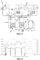
- the figure 4 schematically illustrates a commercial compressor (ATLAS ZT 90 kw from ATLAS COPCO) on which is added a recovery device 5 according to the method of the invention, comprising a (first) connected exchanger system 6 connected as previously described for recovering the heat of the compressed air from the inter-stage, and a (second) heat exchanger system marked 8, connected as previously described to recover the heat of the compressed air of the second stage.
- a commercial compressor ATLAS ZT 90 kw from ATLAS COPCO
- a recovery device 5 comprising a (first) connected exchanger system 6 connected as previously described for recovering the heat of the compressed air from the inter-stage, and a (second) heat exchanger system marked 8, connected as previously described to recover the heat of the compressed air of the second stage.
- the secondary of the two heat exchanger systems 6, 8 are connected in parallel and used to heat the water of a tank (of 1500 liters) circulating in Continuous under the action of a pump I.
- Valves may be provided to distribute the ratio of water flow through the two systems of exchangers.
- the objective of this test report is to follow the performance of the device 5 which comprises two progressive valves 7, 9, as previously described and a control automaton E controlling the two valves 7, 9.
- the test was carried out over a period of 3h (9h to 12h) as shown on the graphs of the Figures 5 to 7 .
- the compressor is started at the index 1, but not the recovery device, the progressive valves 7, 9 being in their position P2 for which the exchanger systems are short-circuited: we notice a graph of the figure 5 that Teal and Tsal, the upstream and downstream air temperature increase very rapidly, the heat not being recovered (between these two points of measurement).
- the recovery device 5 is started at the index 2, namely that the progressive valves 7, 8 open progressively from their position P2 to P1: there is a slight stall temperature Tsal compared to Tea1, the energy taken by the exchanger system 6 being transferred to water: the Tsel temperature increases slightly, avoiding any thermal shock.
- the compressor restarts and recovery with.
- the compressor stops for short periods before starting again, which is normal operation when it reaches its pressure setting.
- the settings of the valves 7 and 9 are modified to achieve Tsel water temperatures of 50 ° C, 60 ° C, 70 ° C, 80 ° C and 85 ° C.
- one of the challenges of the feasibility of the invention is the pressure drop (on the inter-stage air circuit) induced by the recovery device 5. These pressure drops are generated at the inter-stage by the piping, the exchanger system 6, and the progressive valve 7.
- the pressure losses generated by the exchanger system 6 and the pipework are imponderable.
- the progressive valve 7 with a constant flow section (regardless of its percentage of opening) makes it possible to limit the pressure losses with respect to the proportional valves known from the state of the art.
- the pressure drop is controlled by the ⁇ p measurement: this measurement is performed between two points, upstream and downstream of the device on the inter-floor: for this analysis we are particularly interested in the second period of the test ( 10:30 am to 12 noon) and according to the figure 8 . So and at the figure 8 we can clearly see the compressor stops, which translate into ⁇ p drops. These events are marked on the graph by arrows. Then, when the load returns, the ⁇ p rises sharply before going back down: this phenomenon is explained by the rise in pressure of the circuit: at low pressure, the air velocity is higher, the pressure losses are more pronounced. . These two phenomena are to isolate losses of load generated by the equipment.
- the data provided by the manufacturer of the system exchanger 6 gives 0.1 bar of pressure drop.
- the average of the points (excluding idling) gives a ⁇ p of 0.19 bar, which means that the circuit (including the valve 7) generates a pressure drop of 0.09 bar.
- the recovery device according to the invention may be able to react with respect to many parameters related to the operation of the compressor, but also to external parameters.
- the recovered heat is used to heat water taken from a tank.
- a circulator ie a pump marked I makes it possible to take water from the reservoir and convey it to the secondary of the (second) exchanger system 8, and parallel to the secondary (first) of the exchanger system 6, the heated water being recycled to the tank.
- the temperature sensors T9, T10, T11 and T12 make it possible to control the pump of the circulator I; these sensors are also used by the electronics E to decide on the attainment (or not) of the temperature setpoints. It is primarily the temperature of the fluid, in this case water is the main objective of energy recovery.
- the temperature sensors T1, T2, T3, T6 and T8 are used by the electronics E to monitor the operation of the compressor and to regulate the progressive valves 7 and 9: these propositional valves regulate the distribution of flow rates between the exchanger system ( 6 or 8) and the short circuit.
- the regulation by the electronics E allows a progressive temperature rise of the exchanger systems 6 or 8, without thermal shock.
- temperatures T4, T5, T7 and the pressure differential ⁇ p make it possible to monitor the proper operation of the thermal recovery device 5.
- the invention uses one or two progressive valves 7 and / or 9, three channels with constant flow section (motorized) which are notable in that they allow (each) an accurate distribution of flow between the two outputs in function a proportional control signal delivered by the control and control electronics E.
- This valve 7 or 9 is still notable in that it is of constant passage section regardless of the intermediate state of the progressive valve between these extreme positions, namely said first position P1 and said second position P2.
- the figure 10 is a sectional view illustrating an embodiment of this valve.
- valve body may comprise an inlet 74, 94 for the fluid having passed through the exchanger system, the fluid passing through this inlet 74, 94 flowing directly to the second outlet 72, 92 without being blocked by the movable shutter 75, 95.
- the movable shutter 75 (or 95) is a tubular hollow body, pivotally mounted in the valve body, in particular cylindrical.
- the hollow shutter 95 forms the inlet 70, 90 of the valve, the fluid (air) inlet flowing in the hollow of the shutter 75; 95 before exiting through a wall opening of the shutter.
- the shutter 75, 95 can still be rotated by several intermediaries between the two extreme positions, and to distribute the flow between the two outputs 71 and 72 (or 91 and 92) in a controlled percentage.
Landscapes
- Engineering & Computer Science (AREA)
- General Engineering & Computer Science (AREA)
- Mechanical Engineering (AREA)
- Physics & Mathematics (AREA)
- Thermal Sciences (AREA)
- Compressor (AREA)
- Structures Of Non-Positive Displacement Pumps (AREA)
Applications Claiming Priority (1)
| Application Number | Priority Date | Filing Date | Title |
|---|---|---|---|
| FR1850501A FR3077104B1 (fr) | 2018-01-23 | 2018-01-23 | Dispositif de recuperation d'energie thermique |
Publications (2)
| Publication Number | Publication Date |
|---|---|
| EP3514393A2 true EP3514393A2 (de) | 2019-07-24 |
| EP3514393A3 EP3514393A3 (de) | 2019-07-31 |
Family
ID=61873548
Family Applications (1)
| Application Number | Title | Priority Date | Filing Date |
|---|---|---|---|
| EP19152963.5A Withdrawn EP3514393A3 (de) | 2018-01-23 | 2019-01-22 | Vorrichtung zur rückgewinnung von wärmeenergie |
Country Status (2)
| Country | Link |
|---|---|
| EP (1) | EP3514393A3 (de) |
| FR (1) | FR3077104B1 (de) |
Cited By (3)
| Publication number | Priority date | Publication date | Assignee | Title |
|---|---|---|---|---|
| CN111677653A (zh) * | 2020-06-01 | 2020-09-18 | 浙江大学 | 一种回收压缩空气余热并进行预除湿和预冷的空分系统 |
| CN117189685A (zh) * | 2023-09-08 | 2023-12-08 | 丹东顺升机械设备有限公司 | 一种自循环水泵机械密封冷却装置 |
| CN120101389A (zh) * | 2025-05-07 | 2025-06-06 | 浙江科维节能技术股份有限公司 | 一种节能型多级压缩机系统及其节能方法 |
Citations (6)
| Publication number | Priority date | Publication date | Assignee | Title |
|---|---|---|---|---|
| EP2405223A1 (de) | 2010-07-08 | 2012-01-11 | Airflux Société par Actions Simplifiée | Unabhängige Vorrichtung zur Wärmeenergierückgewinnung und -übertragung von Öl auf Wasser |
| CN202520561U (zh) | 2011-12-27 | 2012-11-07 | 上海埃尔特压缩空气系统工程有限公司 | 一种水冷无油螺杆空气压缩机热回收系统 |
| CN203685588U (zh) | 2014-01-27 | 2014-07-02 | 上海瑞晨环保科技有限公司 | 无油螺杆空压机余热回收装置 |
| CN104005959A (zh) | 2014-05-14 | 2014-08-27 | 西安工程大学 | 无油螺杆空压机复合式热回收系统 |
| JP2017015049A (ja) | 2015-07-06 | 2017-01-19 | ダイキン工業株式会社 | 圧縮機 |
| JP2017150496A (ja) | 2017-05-22 | 2017-08-31 | 三浦工業株式会社 | 熱回収システム |
Family Cites Families (7)
| Publication number | Priority date | Publication date | Assignee | Title |
|---|---|---|---|---|
| US2621886A (en) * | 1949-01-27 | 1952-12-16 | Mueller Co | Diverter valve with o ring seal |
| US3938553A (en) * | 1973-11-08 | 1976-02-17 | Robert Ortega | Valve construction |
| IT1184295B (it) * | 1985-07-23 | 1987-10-22 | Giovanni Bonardi | Deviatore per fluidi |
| CN103883505A (zh) * | 2014-01-17 | 2014-06-25 | 上海集熠节能环保技术有限公司 | 一种基于c8051微处理器的空压机余热回收控制系统 |
| CN203758080U (zh) * | 2014-03-05 | 2014-08-06 | 广东芬尼克兹节能设备有限公司 | 一种可控热回收的制冷机系统 |
| JP6677063B2 (ja) * | 2016-04-26 | 2020-04-08 | 三浦工業株式会社 | 熱回収システム |
| CN106524577B (zh) * | 2016-11-25 | 2018-05-01 | 重庆美的通用制冷设备有限公司 | 热泵机组 |
-
2018
- 2018-01-23 FR FR1850501A patent/FR3077104B1/fr not_active Expired - Fee Related
-
2019
- 2019-01-22 EP EP19152963.5A patent/EP3514393A3/de not_active Withdrawn
Patent Citations (6)
| Publication number | Priority date | Publication date | Assignee | Title |
|---|---|---|---|---|
| EP2405223A1 (de) | 2010-07-08 | 2012-01-11 | Airflux Société par Actions Simplifiée | Unabhängige Vorrichtung zur Wärmeenergierückgewinnung und -übertragung von Öl auf Wasser |
| CN202520561U (zh) | 2011-12-27 | 2012-11-07 | 上海埃尔特压缩空气系统工程有限公司 | 一种水冷无油螺杆空气压缩机热回收系统 |
| CN203685588U (zh) | 2014-01-27 | 2014-07-02 | 上海瑞晨环保科技有限公司 | 无油螺杆空压机余热回收装置 |
| CN104005959A (zh) | 2014-05-14 | 2014-08-27 | 西安工程大学 | 无油螺杆空压机复合式热回收系统 |
| JP2017015049A (ja) | 2015-07-06 | 2017-01-19 | ダイキン工業株式会社 | 圧縮機 |
| JP2017150496A (ja) | 2017-05-22 | 2017-08-31 | 三浦工業株式会社 | 熱回収システム |
Cited By (4)
| Publication number | Priority date | Publication date | Assignee | Title |
|---|---|---|---|---|
| CN111677653A (zh) * | 2020-06-01 | 2020-09-18 | 浙江大学 | 一种回收压缩空气余热并进行预除湿和预冷的空分系统 |
| CN117189685A (zh) * | 2023-09-08 | 2023-12-08 | 丹东顺升机械设备有限公司 | 一种自循环水泵机械密封冷却装置 |
| CN117189685B (zh) * | 2023-09-08 | 2024-03-29 | 丹东顺升机械设备有限公司 | 一种自循环水泵机械密封冷却装置 |
| CN120101389A (zh) * | 2025-05-07 | 2025-06-06 | 浙江科维节能技术股份有限公司 | 一种节能型多级压缩机系统及其节能方法 |
Also Published As
| Publication number | Publication date |
|---|---|
| FR3077104B1 (fr) | 2020-01-03 |
| FR3077104A1 (fr) | 2019-07-26 |
| EP3514393A3 (de) | 2019-07-31 |
Similar Documents
| Publication | Publication Date | Title |
|---|---|---|
| EP2961966B1 (de) | Verfahren und vorrichtung zur regelung der ölkühlung in einer turbomaschin | |
| FR2715211A1 (fr) | Procédé d'exploitation d'un système de réfrigération et système de réfrigération fonctionnant selon ce procédé. | |
| EP2720890B1 (de) | Kältemittelkreislauf und verfahren zur steuerung eines solchen kreislaufs | |
| FR2970501A1 (fr) | Systeme et procede pour reguler un ecoulement dans un rotor | |
| FR3077104A1 (fr) | Dispositif de recuperation d'energie thermique | |
| FR2978506A1 (fr) | Circuit de commande hydraulique | |
| FR2964450A1 (fr) | Procede de controle d'une vanne de detente | |
| EP3867531B1 (de) | Verfahren zur regelung der temperatur einer vakuumpumpe und zugehörige vakuumpumpe und anlage | |
| EP2863130B1 (de) | Verfahren zur Regulierung einer thermischen Anlage für ein Gebäude | |
| WO2014118384A1 (fr) | Installation a turbine a gaz et procede de regulation de ladite installation. | |
| EP1490637B1 (de) | Tiefkühltunnel und verfahren zum betrieb eines solchen tunnels | |
| EP3418192A1 (de) | System zur rückgewinnung von wärmeenergie eines hauptleistungsübertragungsgetriebes eines luftfahrzeugs zur beheizung der kabine des luftfahrzeugs | |
| WO2009125090A1 (fr) | Système et procédé de réchauffage du fluide hydraulique d'un aéronef | |
| FR3064604B1 (fr) | Procede de pilotage d'une baie multimoteurs, systeme de commande pour baie multimoteurs et baie multimoteurs | |
| EP2729744B1 (de) | Verfahren zum ausgleich von schmiermittelkonzentrationen in einem mehrstufiger verdichtungseinehit eines wärmeaustauschsystems und wärmeaustauschsystem zur umsetzung dieses verfahrens | |
| FR2940410A1 (fr) | Installation frigorifique comprenant deux circuits en cascade. | |
| WO2025228861A1 (fr) | Dispositif de management thermique d'un véhicule électrique | |
| FR3166330A1 (fr) | Système de conditionnement d’air pour véhicule et procédé de contrôle associé | |
| FR3023587A1 (fr) | Turbomachine a systeme de refroidissement autonome d'equipements. | |
| WO2025099027A1 (fr) | Dispositif de management thermique à propane pour véhicule, notamment à propulsion électrique | |
| FR3058933A1 (fr) | Boucle de circulation d'un fluide refrigerant pour le conditionnement d'air d'habitacle d'un vehicule | |
| FR3163609A1 (fr) | Dispositif de management thermique d’un véhicule comportant une chaine de traction électrique | |
| FR3154980A1 (fr) | Procédé de surveillance de turbomachine | |
| FR3161878A1 (fr) | Dispositif de management thermique d’un véhicule électrique. | |
| FR2938050A1 (fr) | Boucle de climatisation comprenant une vanne en entree du compresseur |
Legal Events
| Date | Code | Title | Description |
|---|---|---|---|
| PUAI | Public reference made under article 153(3) epc to a published international application that has entered the european phase |
Free format text: ORIGINAL CODE: 0009012 |
|
| STAA | Information on the status of an ep patent application or granted ep patent |
Free format text: STATUS: THE APPLICATION HAS BEEN PUBLISHED |
|
| PUAL | Search report despatched |
Free format text: ORIGINAL CODE: 0009013 |
|
| AK | Designated contracting states |
Kind code of ref document: A2 Designated state(s): AL AT BE BG CH CY CZ DE DK EE ES FI FR GB GR HR HU IE IS IT LI LT LU LV MC MK MT NL NO PL PT RO RS SE SI SK SM TR |
|
| AX | Request for extension of the european patent |
Extension state: BA ME |
|
| AK | Designated contracting states |
Kind code of ref document: A3 Designated state(s): AL AT BE BG CH CY CZ DE DK EE ES FI FR GB GR HR HU IE IS IT LI LT LU LV MC MK MT NL NO PL PT RO RS SE SI SK SM TR |
|
| AX | Request for extension of the european patent |
Extension state: BA ME |
|
| STAA | Information on the status of an ep patent application or granted ep patent |
Free format text: STATUS: THE APPLICATION IS DEEMED TO BE WITHDRAWN |
|
| 18D | Application deemed to be withdrawn |
Effective date: 20200201 |