EP3514442B1 - Lampe à lumière diffuse à encombrement en hauteur optimisé - Google Patents
Lampe à lumière diffuse à encombrement en hauteur optimisé Download PDFInfo
- Publication number
- EP3514442B1 EP3514442B1 EP18206455.0A EP18206455A EP3514442B1 EP 3514442 B1 EP3514442 B1 EP 3514442B1 EP 18206455 A EP18206455 A EP 18206455A EP 3514442 B1 EP3514442 B1 EP 3514442B1
- Authority
- EP
- European Patent Office
- Prior art keywords
- light
- device carrier
- frame
- bolts
- mounting frame
- Prior art date
- Legal status (The legal status is an assumption and is not a legal conclusion. Google has not performed a legal analysis and makes no representation as to the accuracy of the status listed.)
- Active
Links
Images





Classifications
-
- F—MECHANICAL ENGINEERING; LIGHTING; HEATING; WEAPONS; BLASTING
- F21—LIGHTING
- F21V—FUNCTIONAL FEATURES OR DETAILS OF LIGHTING DEVICES OR SYSTEMS THEREOF; STRUCTURAL COMBINATIONS OF LIGHTING DEVICES WITH OTHER ARTICLES, NOT OTHERWISE PROVIDED FOR
- F21V17/00—Fastening of component parts of lighting devices, e.g. shades, globes, refractors, reflectors, filters, screens, grids or protective cages
- F21V17/10—Fastening of component parts of lighting devices, e.g. shades, globes, refractors, reflectors, filters, screens, grids or protective cages characterised by specific fastening means or way of fastening
- F21V17/16—Fastening of component parts of lighting devices, e.g. shades, globes, refractors, reflectors, filters, screens, grids or protective cages characterised by specific fastening means or way of fastening by deformation of parts; Snap action mounting
- F21V17/162—Fastening of component parts of lighting devices, e.g. shades, globes, refractors, reflectors, filters, screens, grids or protective cages characterised by specific fastening means or way of fastening by deformation of parts; Snap action mounting the parts being subjected to traction or compression, e.g. coil springs
-
- F—MECHANICAL ENGINEERING; LIGHTING; HEATING; WEAPONS; BLASTING
- F21—LIGHTING
- F21V—FUNCTIONAL FEATURES OR DETAILS OF LIGHTING DEVICES OR SYSTEMS THEREOF; STRUCTURAL COMBINATIONS OF LIGHTING DEVICES WITH OTHER ARTICLES, NOT OTHERWISE PROVIDED FOR
- F21V23/00—Arrangement of electric circuit elements in or on lighting devices
- F21V23/02—Arrangement of electric circuit elements in or on lighting devices the elements being transformers, impedances or power supply units, e.g. a transformer with a rectifier
- F21V23/026—Fastening of transformers or ballasts
-
- F—MECHANICAL ENGINEERING; LIGHTING; HEATING; WEAPONS; BLASTING
- F21—LIGHTING
- F21S—NON-PORTABLE LIGHTING DEVICES; SYSTEMS THEREOF; VEHICLE LIGHTING DEVICES SPECIALLY ADAPTED FOR VEHICLE EXTERIORS
- F21S8/00—Lighting devices intended for fixed installation
- F21S8/04—Lighting devices intended for fixed installation intended only for mounting on a ceiling or the like overhead structures
-
- F—MECHANICAL ENGINEERING; LIGHTING; HEATING; WEAPONS; BLASTING
- F21—LIGHTING
- F21V—FUNCTIONAL FEATURES OR DETAILS OF LIGHTING DEVICES OR SYSTEMS THEREOF; STRUCTURAL COMBINATIONS OF LIGHTING DEVICES WITH OTHER ARTICLES, NOT OTHERWISE PROVIDED FOR
- F21V17/00—Fastening of component parts of lighting devices, e.g. shades, globes, refractors, reflectors, filters, screens, grids or protective cages
- F21V17/10—Fastening of component parts of lighting devices, e.g. shades, globes, refractors, reflectors, filters, screens, grids or protective cages characterised by specific fastening means or way of fastening
- F21V17/16—Fastening of component parts of lighting devices, e.g. shades, globes, refractors, reflectors, filters, screens, grids or protective cages characterised by specific fastening means or way of fastening by deformation of parts; Snap action mounting
- F21V17/164—Fastening of component parts of lighting devices, e.g. shades, globes, refractors, reflectors, filters, screens, grids or protective cages characterised by specific fastening means or way of fastening by deformation of parts; Snap action mounting the parts being subjected to bending, e.g. snap joints
-
- F—MECHANICAL ENGINEERING; LIGHTING; HEATING; WEAPONS; BLASTING
- F21—LIGHTING
- F21V—FUNCTIONAL FEATURES OR DETAILS OF LIGHTING DEVICES OR SYSTEMS THEREOF; STRUCTURAL COMBINATIONS OF LIGHTING DEVICES WITH OTHER ARTICLES, NOT OTHERWISE PROVIDED FOR
- F21V17/00—Fastening of component parts of lighting devices, e.g. shades, globes, refractors, reflectors, filters, screens, grids or protective cages
- F21V17/10—Fastening of component parts of lighting devices, e.g. shades, globes, refractors, reflectors, filters, screens, grids or protective cages characterised by specific fastening means or way of fastening
- F21V17/18—Latch-type fastening, e.g. with rotary action
-
- F—MECHANICAL ENGINEERING; LIGHTING; HEATING; WEAPONS; BLASTING
- F21—LIGHTING
- F21V—FUNCTIONAL FEATURES OR DETAILS OF LIGHTING DEVICES OR SYSTEMS THEREOF; STRUCTURAL COMBINATIONS OF LIGHTING DEVICES WITH OTHER ARTICLES, NOT OTHERWISE PROVIDED FOR
- F21V21/00—Supporting, suspending, or attaching arrangements for lighting devices; Hand grips
- F21V21/02—Wall, ceiling, or floor bases; Fixing pendants or arms to the bases
-
- F—MECHANICAL ENGINEERING; LIGHTING; HEATING; WEAPONS; BLASTING
- F21—LIGHTING
- F21V—FUNCTIONAL FEATURES OR DETAILS OF LIGHTING DEVICES OR SYSTEMS THEREOF; STRUCTURAL COMBINATIONS OF LIGHTING DEVICES WITH OTHER ARTICLES, NOT OTHERWISE PROVIDED FOR
- F21V3/00—Globes; Bowls; Cover glasses
- F21V3/02—Globes; Bowls; Cover glasses characterised by the shape
-
- F—MECHANICAL ENGINEERING; LIGHTING; HEATING; WEAPONS; BLASTING
- F21—LIGHTING
- F21Y—INDEXING SCHEME ASSOCIATED WITH SUBCLASSES F21K, F21L, F21S and F21V, RELATING TO THE FORM OR THE KIND OF THE LIGHT SOURCES OR OF THE COLOUR OF THE LIGHT EMITTED
- F21Y2103/00—Elongate light sources, e.g. fluorescent tubes
- F21Y2103/10—Elongate light sources, e.g. fluorescent tubes comprising a linear array of point-like light-generating elements
-
- F—MECHANICAL ENGINEERING; LIGHTING; HEATING; WEAPONS; BLASTING
- F21—LIGHTING
- F21Y—INDEXING SCHEME ASSOCIATED WITH SUBCLASSES F21K, F21L, F21S and F21V, RELATING TO THE FORM OR THE KIND OF THE LIGHT SOURCES OR OF THE COLOUR OF THE LIGHT EMITTED
- F21Y2115/00—Light-generating elements of semiconductor light sources
- F21Y2115/10—Light-emitting diodes [LED]
-
- G—PHYSICS
- G02—OPTICS
- G02B—OPTICAL ELEMENTS, SYSTEMS OR APPARATUS
- G02B6/00—Light guides; Structural details of arrangements comprising light guides and other optical elements, e.g. couplings
- G02B6/0001—Light guides; Structural details of arrangements comprising light guides and other optical elements, e.g. couplings specially adapted for lighting devices or systems
- G02B6/0011—Light guides; Structural details of arrangements comprising light guides and other optical elements, e.g. couplings specially adapted for lighting devices or systems the light guides being planar or of plate-like form
-
- G—PHYSICS
- G02—OPTICS
- G02B—OPTICAL ELEMENTS, SYSTEMS OR APPARATUS
- G02B6/00—Light guides; Structural details of arrangements comprising light guides and other optical elements, e.g. couplings
- G02B6/0001—Light guides; Structural details of arrangements comprising light guides and other optical elements, e.g. couplings specially adapted for lighting devices or systems
- G02B6/0011—Light guides; Structural details of arrangements comprising light guides and other optical elements, e.g. couplings specially adapted for lighting devices or systems the light guides being planar or of plate-like form
- G02B6/0066—Light guides; Structural details of arrangements comprising light guides and other optical elements, e.g. couplings specially adapted for lighting devices or systems the light guides being planar or of plate-like form characterised by the light source being coupled to the light guide
- G02B6/0073—Light emitting diode [LED]
Definitions
- the present invention relates to a so-called surface lamp, in which various measures are provided, with the help of which the overall height of the lamp can be reduced. Furthermore, the invention relates to a surface light, the assembly of which is simplified.
- Area lights are understood to mean lights which are designed in such a way that light is emitted essentially uniformly over a larger, usually rectangular area. Uniform or homogeneous light emission is understood here to mean that the color or the color temperature of the emitted light is essentially the same over the entire area over which light is emitted and the luminous area also appears uniformly bright overall. In particular, no individual light sources or strong differences in brightness should be recognizable.
- Luminaires of the type described above can be realized both as surface-mounted lights and as suspended lights. Since these luminaires generally have larger dimensions, since they are to be used to realize large-area illuminated areas, it is usually desirable for the height of the luminaire to be comparatively low. This applies both in the case of a suspended luminaire and for the installation, for example, on a ceiling of a room to be illuminated.
- the light emitted by the LEDs and coupled into the light guide arrangement is then distributed with the aid of reflections and then decoupled in a suitable manner, so that a homogeneous, uniform light emission can be achieved over the entire surface.
- This The type of light distribution and light emission also has the advantage that any small differences in the color or color temperature of the light emitted by the individual LEDs are compensated for, since the light is mixed appropriately before it leaves the light guide. Furthermore, since the light sources are not positioned on the back of the light guide arrangement, but on the side thereof, a very low height can be achieved for the components which are responsible for the light generation and light emission.
- a lamp with such a light guide is for example from the US 9,069,106 B1 known.
- the present invention is based on the task of additionally optimizing area lights of the type described with regard to their overall height. Furthermore, the invention is based on the object of specifying a surface light, the assembly of which is simplified.
- the light guide technology described above is also used in the luminaire according to the invention, in which the light sources are positioned laterally to form a flat light guide or a light guide arrangement in such a way that the light is coupled into the light guide via a narrow side and perpendicularly to it aligned light exit surface is emitted.
- the measures according to the invention now relate to further components of the luminaire, the influence of which on the overall overall height has so far been neglected. It has been shown that improvements here can lead to an additional reduction in the overall height of the luminaire.
- the invention relates to measures relating to the assembly of the lamp, in particular in the event that the lamp is designed as a so-called surface-mounted lamp.
- a rear area of the lamp should be attached as close as possible to a support surface, for example on the ceiling of a room to be illuminated, the attachment measures should be carried out in such a way that they easily attach the lamp and later loosen the attachment, for example for maintenance purposes.
- the fastening measures should ideally not be visible to observers.
- the mounting frame here has a frame-like area, on the sides of which webs extend downward, two of these webs forming mutually opposite guides for the bolts and the bolts each abutting the inside of the webs.
- a surface light is accordingly proposed with a plate-shaped light guide element and light sources arranged on at least one narrow side of the light guide element, the light of which is coupled into the light guide element via a light entry surface formed by the narrow side and emitted via a light exit surface oriented essentially perpendicular to the light entry surface.
- a flat device carrier is provided on the side of the light guide element opposite the light exit surface, on which at least one operating device for the illuminants is arranged
- the lamp also has a mounting frame which is detachably connectable to the device carrier and is designed for attachment to a carrier surface, for example on the ceiling of a room to be illuminated
- the detachable connection between the device carrier and the mounting frame has two bolts which are arranged on the mounting frame so as to be displaceable and for locking with at least one each are arranged on the device carrier arranged locking element, the bolts for releasing the locking are movable in a direction parallel to the plane of the light guide element
- the mounting frame has a frame-like region, on the sides of which webs extend downward, two of these webs forming mutually opposite guides for the bolts and the bolts each abutting the inside of the webs.
- the latches are in particular designed in such a way that they project beyond the mounting frame on both sides and can therefore be actuated from both sides. Regardless of the positioning of the luminaire according to the invention on a ceiling, the locking mechanism is therefore always accessible and operable.
- the bolts are biased into a closed position, which is achieved in particular with the aid of suitable spring elements.
- the latches are preferably also designed in such a way that when the luminaire or the device carrier is attached to the mounting frame for the assembly of the luminaire they migrate automatically into an open position, so that the latches themselves only have to be actuated to release the latching, however, when the luminaire is installed an automatic locking is achieved.
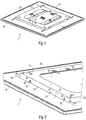
- an area light according to the invention is shown, which in the exemplary embodiment shown is designed for a ceiling extension.
- the measures according to the invention initially described relate to the rear area, that is to say the area of the luminaire 1, which lies opposite the actual light emission surface.
- the lamp 1 has an approximately square shape, but the solutions according to the invention are not limited to the shape shown. In the same way, the luminaire 1 could also be rectangular or oval or circular, for example.
- the actual lamp body has a relatively flat height and is surrounded by a circumferential frame 20 which serves to hold the components for light generation and light emission which will be described in more detail later.
- a square cover 25 is provided, which covers the frame 20 Covering the area to the rear, but has openings 26 on the peripheral area, which allow a small proportion of the light generated by the lamps to exit to the rear.
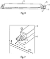
- the device carrier 30 On the cover 25 formed, for example, from sheet metal, there is also an in at the rear of the lamp body Figure 3 Arranged device carrier 30, which can be seen in more detail and which serves to hold components, which are described in more detail below, and which are responsible for generating a suitable voltage for operating the lamps.
- the device carrier 30 also serves to mount the lamp 1 on a ceiling, the device carrier 30 not being attached directly to the ceiling for this purpose, but rather being connectable to a mounting frame 50 provided for this purpose.
- the mounting frame 50 itself is fixed to a support surface, that is to say, for example, to the ceiling of a room to be illuminated, this preferably being done via a screw connection.
- the actual lamp is then attached to the mounting frame 50 via the device carrier 30.
- the attachment is in particular tool-free and is - as described in more detail below - designed in a special way to ensure a low overall height of the fastening measures.
- the mounting frame 50 can be locked with the device carrier 30, which, as already mentioned, is fixed on the back of the cover 25.
- two specially designed locking bolts 60 are provided, which are slidably attached to the mounting frame 50 and lock with the device carrier 30 in the manner described in more detail below.
- the mounting frame 50 is initially designed in such a way that it has a flat, frame-like region 51 which encloses an approximately square opening 52 and, when fixed to the ceiling, bears against the latter.
- the opening 52 makes sense insofar as this enables the connection of power supply cables to connection terminals which are fastened to the device carrier 30.
- Corresponding webs 53 and 54 each extend downward from the frame-like region 51, two of these webs 53 forming mutually opposite guides for the latch bolts 60.
- the latches 60 each abut the inside of the webs 53 and are each mounted by means of two slide bearings 58 such that they can be moved along the webs 53.
- the bars 60 are also guided in the end regions of the webs 53 in that the two further webs 54 of the mounting element 50 have corresponding slots in their end regions, through which the bolts 60 extend.
- the webs 53 each have two latching openings 55, which are designed to widen on their underside and accordingly have run-on bevels.
- the latches 60 also have openings 61, which are initially designed to widen towards the bottom, but have a latching projection 62 with a horizontal bearing surface 63.
- the bolts 60 which protrude on both sides of the mounting frame 50 and are angled at their ends for better actuation, are prestressed into the position shown in the figures with the aid of a tension spring 65.
- the tension spring 65 engages on the one hand on the bolt 60 itself and on the other hand on the web 53 of the mounting frame 50 or a correspondingly inwardly projecting pin 56 and pulls the bolt 60 in the illustration of FIG Figures 4 and 5 to the left.
- the latch 60 is prestressed to the left by the tension spring 65 so that in the initial state the latching projection 62 overlaps with the corresponding wall region 57 of the latching opening 55 of the web 53.
- both bevels of the latch 60 and the latching opening 55 form a triangle open at the bottom, which enables the insertion of a latching element.
- This locking element is locking pins 39 which are fastened to the device carrier 30.
- the device carrier 30 also has, starting from a flat plate-shaped region 31 on its circumference, webs 32 which are oriented perpendicularly thereto, two latching pins 39 each being fastened to two webs 32 lying opposite one another. This can be done in that the locking pins 39 are guided through corresponding openings in the webs 32 of the device carrier 30. They protrude outward beyond the webs 32 into the area of the webs 53 of the mounting frame 50.
- the end regions of the latching pins 39 initially engage in the triangular insertion areas when the lamp is correctly positioned, which are caused by the bevels of the latching openings 55, 61 of the mounting frame 50 or the latch 60 are formed.
- the bolts 60 migrate laterally against the spring force until the pins 39 pass the locking projection 62.
- the bolt then snaps back into the starting position due to the spring 65, with the support surface 63 of the locking projection 62 now engaging under the associated locking pin 39.
- the result of the horizontal contact surface 63 is that the latch 60 will no longer move to the open position independently, but rather the latching can only be released again by deliberately pulling the latch 60 into the open position.
- a very simple but efficient fastening of the lamp to the mounting frame 50 is thus achieved with the aid of the solution according to the invention.
- a secure mounting of the luminaire is ensured, since the spring 65 does not have to counteract the weight of the luminaires and accordingly the two latches 60 can hold luminaires with a higher weight without any problems.
- the device carrier 30 is held reliably in four distributed positions, so that the lamp is kept stable on the ceiling overall.
- the device carrier 30 serves not only to fasten the lamp to the mounting frame 50, but in particular also to hold electrical components for supplying power to the lamps. In particular, these can be control gear or connecting terminals. If the luminaire should also have a so-called emergency light function, an accumulator is often also attached to the equipment rack. Measures will now be described below with the help of which the resulting overall height can be reduced.
- the components to be fastened to the device carrier 30 should be arranged lying on a flat side of the device carrier 30 and then screwed or locked to the device carrier 30.
- the fastening elements used here for example screws or locking pins, then penetrated the device carrier 30 and protruded on the side opposite the components to be fastened.
- the device carrier 30 would have to be at a certain distance from the cover 25, since otherwise the protruding locking elements would collide with the cover 25.
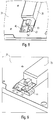
- FIG. 6 shows a first variant with which the resulting height can be reduced overall.
- an operating device 70 which is to be attached to the device carrier 30.
- the operating device 70 has projections 71, 73 with recesses 72, 74 on its opposite end regions, which allow screwing to the device carrier 30.
- a special feature, however, is that the two end regions are designed so that only one recess 72 is located on both sides - as was previously the case - at the level of the operating device 70, while the second recess 74 is on one compared to the floor surface raised projection 73 executed.
- the device carrier 30 itself has, in its plate-shaped region 31, a recess 40 which essentially corresponds to the shape of the operating device 70 to be fastened and which has contact surfaces 41 with associated screw openings 42 only in corner regions which correspond to the raised projections 73 of the operating device 70.
- the operating device 70 can now be positioned in the associated recess 40 of the device carrier 30 such that the raised projections 73 rest on the bearing surfaces 41.
- the operating device 70 can then be screwed to the device carrier 30 via the corresponding recess 74 and the associated opening 42.
- the advantage of the solution shown is that although the screw 43 in turn penetrates the plate-shaped region 31 of the device carrier 30 and thus protrudes on the opposite side, the screw 43 now does not project beyond the bottom surface of the operating device 70.
- the increased arrangement of the projection 73 compared to the bottom surface has the consequence that the operating device 70 is arranged in a recess in the recess 40 of the device carrier 30 and also projects beyond the underside of the device carrier 30. This supernatant preferably corresponds to the protrusion of the screw 43.
- the device carrier 30 must have a certain minimum distance from the cover 25, since neither the screw 43 nor the base of the operating device 70 should collide with the cover 25 due to the recessed arrangement
- the operating device 70 now only protrudes at the top by a small amount above the surface of the device carrier 30.
- the total height of the resulting arrangement consisting of device carrier 30, control gear 70 and screws 43 thus only corresponds to the height of control gear 70 itself, so that a height reduction is achieved compared to previously known solutions.
- FIG. 9 One compared to the Figures 7 and 8th slightly modified variant of the attachment of the operating device 70 to the device carrier 30 is in Figure 9 shown.
- the operating device 70 in turn lies on the plate-shaped area 31 of the device carrier 30 essentially over the entire surface.
- an elevated contact area 44 is now formed, for example, by a corresponding configuration in comparison to the plate-shaped area 31, which in turn enables the operating device 70 to be screwed to the device carrier 30 by means of an opening (not visible).
- the raised contact surface 44 ensures that the screw 43 does not protrude beyond the underside of the plate-shaped area 31 of the device carrier 30.
- the Figures 10 and 11 also show alternative options for storing an operating device, which are essentially further developments of the Figures 7 and 8th presented concept.
- the operating device 70 is mounted in the plane of the plate-shaped region 31 of the device carrier 30, so that the operating device 70 protrudes on both sides.
- the attachment of the operating device 70 to the device carrier can then, for example, as in FIG Figure 11 shown using a clamping spring 46, which is U-shaped and overlaps the operating device 70. With corresponding locking areas, the clamping spring 46 then engages in suitable openings in the device carrier 30 and fixes the operating device 70 thereon. The lower positioning of the operating device 70 in turn ensures that the locking of the spring 46 with the device carrier 30 does not lead to an increase in the overall height of the arrangement as a whole.
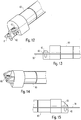
- FIGS Figures 12 and 13 first show a first example of a rechargeable battery 80, the end regions of which, like the operating device, are shown in FIGS Figures 6 to 9 are designed.
- the accumulator 80 has at its opposite end regions two surfaces 81 and 82 which are offset in height from one another and have corresponding screw openings, the fastening of the accumulator 80 to the device carrier 30 then in an analogous manner to that in FIGS Figures 8 and 9 shown is done.
- a surface 82 is positioned higher than the bottom area of the accumulator 80, so that - as in FIG Figure 13 shown - the screw 43 screwed to the device carrier 30 does not protrude beyond the underside of the battery 80 in the assembled state.
- Figure 13 shows very clearly that the total height of the arrangement is determined exclusively by the height of the accumulator 80 and that no further additional heights or dimensions need to be taken into account.
- the Figures 14 and 15 show an alternative variant of the rechargeable battery 80, in which the end region has only a single contact surface 83 with a corresponding screw opening, the contact surface 83 in turn being increased compared to the bottom surface of the rechargeable battery 80.
- the end region of a lamp operating device 70 can also be designed.
- the storage of the battery could of course also, as in the Figures 10 and 11 explained on the basis of the operating device 70.
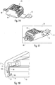
- connection terminal 85 which is also to be attached in this way to the device carrier 30.
- the clamp 85 here has protrusions on both sides of the actual clamp body 86, which are designed such that they are angled such that their end regions are positioned higher than the bottom surface of the clamp 85.
- the end regions 87 and 88 then in turn have corresponding openings which make it possible to screw or latch the clamp 85 to the device carrier 30.
- the device carrier 30 has - as in FIG Figure 17 shown - a corresponding recess in which the clamp 85 is ultimately slightly recessed.
- the measures described thus contribute to the fact that the fastening of the various components to the device carrier 30 does not lead to a substantial increase in the overall height of the lamp 1 as a whole.
- the height can even be reduced compared to previously known solutions.
- Another aspect relates to the arrangement and mounting of a transparent cover within the lamp frame 20, the light from the lamp 1 ultimately being emitted via this cover.
- a so-called frameless mounting of the cover is provided. That is, the cover does not rest on a protrusion of the peripheral frame 20, but is held by it in such a way that it is positioned flush with the underside of the frame 30, wherein a slight gap can remain between the outer circumference of the cover and the frame 20.
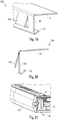
- FIG. 18 to 20 a first variant is shown to solve this problem. Shown here are the frame profile 21 in section and the cover 90 held by the frame 20.
- the cover 90 can, for example, be part of a multilayer light guide arrangement which consists of several plate-shaped elements.
- the illuminants will then be positioned on the circumference of a further light guide plate resting above the cover 90, into which the light of the illuminants is coupled and then distributed over a large area.
- This light guide plate and LEDs are in Figure 18 not shown, since the holding of the cover 90 is to be explained in the first place.
- the cover 90 has, as usual, a circumferential groove 91, via which attachment to the frame 20 takes place.
- a spring element of the frame profile part 21 does not itself engage in the groove 91, but instead it is provided that the frame 20 and cover 90 are clamped with the aid of separate spring elements 100.
- These spring elements 100 are in perspective and in section in FIGS Figures 19 and 20 shown and each consist of a corresponding stamped and shaped sheet metal part.
- the spring element 100 is in this case angled with two main legs 101 and 102, the vertically oriented leg 102 being provided at its lower end for the clamping engagement in the groove 91 of the cover 90 and for this purpose having a bend 103 .
- individual spring areas 104 are punched out in the vertical leg 102 and bent outward. These are provided for engagement in an inward-facing, circumferential further groove 22 of the frame profile part 21.
- the horizontal leg 101 in turn overlaps the elements resting on the cover 90, that is to say in particular the light guide arrangement and a cover optionally arranged on the rear side thereof, and further enables the spring elements 100 to be snapped on to the side of the cover 90 and the elements resting thereon.
- the frame 20 can then be clamped to the cover 90 or the spring elements 100, which is done by inserting the cover 90 into the frame 20 from the underside.
- the spring areas 104 slide along a corresponding inner edge 23 of the frame profile parts 21 until they can snap into the groove 22.
- the springs 100 now being able to compensate for differences in expansion and manufacturing tolerances.
- FIGS 21 to 24 show a second variant of a connection of frame 20 and cover 90, the cover 90 now not directly having the circumferential groove required for jamming, but instead being formed on a holding element 95 which is attached to the cover 90 in the edge region, for example on the back of the light emitting side is glued to it.
- the holding element 95 also serves to support the LED boards 10 with the associated LEDs 11.
- the holding element 95 in particular also holds the plate-shaped light guide 15, into which the LED light is coupled in laterally.
- a multi-layer light guide arrangement is used, which contains additional plate-shaped elements or foils, which ensure better mixing and distribution of the light.
- a single light guide plate it would also be conceivable for a single light guide plate to be used.
- cover 90 is held by the holding element 95 and, in addition, also the LED patins 10 and the light guide plate 15.
- This unit consisting of cover 90, holding element 95 and the further components of the light fixture held therefrom should then again be held frameless by frame 20, separate spring elements 105 being again provided, which are responsible for the clamping connection.
- spring elements 105 which in particular in Figure 23 are in turn formed by correspondingly punched and shaped sheet metal parts, and in the present case they also serve to hold the rear cover 25.
- the spring elements 105 are first positioned on a circumferential, downwardly directed web 27 of the cover 25 on the inside thereof.
- corresponding projections 106 which in turn can be formed by embossing, the spring elements 105 then pass through corresponding openings in the vertical web 27 of the cover 25.
- these projections 106 engage in the circumferential groove 22 of the frame profile parts 21, so that initially with the aid of the spring elements 105 a connection between frame 20 and cover 25 is achieved.
- the finished frame to be connected to the cover 25 with the aid of the spring elements 105.
- the unit consisting of cover 90, holding element 95 and the further components held by it is then inserted into frame 20 and fixed with the aid of spring elements 105.
- the spring elements 105 additionally have punched-out spring regions 107, which now project inwards and are designed for a clamping engagement in the outwardly directed groove 96 of the holding elements 95.
- the spring regions 107 slide from above along the upper edge of the holding elements 95 until they snap into the groove 96, in which case the frame 20 and the cover 90 are then clamped.
- the separate spring elements 105 have the advantage that they can be designed in a corresponding manner in order to be able to compensate for manufacturing tolerances and temperature-related expansions.
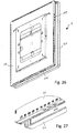
- a third solution for holding the lamp frame 20 is in the Figures 25 to 29 shown.
- the light 1 corresponds to the variants of the surface light according to the invention shown in the previous figures, which is why comparable elements are shown with comparable reference numerals.
- a light guide plate 15 is used, on the edge areas of which LED boards 10 are arranged, with the aid of holding elements 95, on the one hand, the LED boards 10 with the associated LEDs 11 and the light guide plate 15 are held.
- the holding elements 95 also serve to hold the lamp cover 90, and in turn a multilayer structure of plate-shaped elements is provided, via which the light distribution and light emission is achieved in the desired manner. This in turn creates a structural unit that can be preassembled and can then be used as a whole when the lamp 1 is assembled.
- the frame 20 itself in turn points according to the sectional view of FIG Figure 29 a groove 22 running on the inner circumference, into which the springs 109 are to engage, as is shown in the sectional view of FIG Figure 25 is recognizable. Furthermore, the frame 20 has on its underside a slightly inwardly projecting web 24, which then rests in the locked state with the rest of the lamp 1 on the underside of the cover 90 and thus additionally fixes it. Possibly. could be dispensed with on this web 24 in order to achieve a classic "frameless" design of the lamp 1.
- the individual components are first assembled in such a way that the in Figure 28 recognizable structural unit results.
- the components responsible for generating and emitting light are already attached to the rear cover 25.
- the frame 20 is then attached to this unit from the underside and moved upwards until the springs 109 snap into the circumferential groove 22.
- the frame thus again clearly represents an independent structural unit in comparison to previously known solutions, which is attached to the lamp as a whole.
- the luminaire frame is therefore not formed by fastening individual frame parts to the luminaire, but rather can be attached to the luminaire as a closed structural unit, which has clear advantages with regard to the design options for the frame.
- this can be shaped before the final attachment to the lamp and appropriately painted or coated so that no joints or comparable gaps or gaps can be seen. This applies both to the square luminaire shape shown and to any other surface shape. Apart from the fact that this simplifies the assembly of the lamp, the appearance of the lamp itself can be significantly improved.
- the various measures described provide possibilities to reduce the overall height of a surface luminaire. Furthermore, simple assembly and an efficient possibility of connecting the lamps to an operating device are provided.
Landscapes
- Engineering & Computer Science (AREA)
- General Engineering & Computer Science (AREA)
- Power Engineering (AREA)
- Planar Illumination Modules (AREA)
- Fastening Of Light Sources Or Lamp Holders (AREA)
- Securing Globes, Refractors, Reflectors Or The Like (AREA)
Claims (4)
- Panneau lumineux (1) avec un élément de guidage de lumière (15) en forme de plaque, ainsi que des moyens d'éclairage (10) disposés au moins sur un côté étroit de l'élément de guidage de lumière (15), dont la lumière est introduite par l'intermédiaire d'une surface d'entrée de lumière formée par le côté étroit, dans l'élément de guidage de lumière (15) et est émise par l'intermédiaire d'une surface de sortie de lumière orientée globalement perpendiculairement par rapport à la surface d'entrée de lumière,
dans lequel, sur le côté de l'élément de guidage de lumière (15) opposé à la surface de sortie de lumière, est prévu un support d'appareil plat (30) sur lequel est disposé au moins un appareil de commande (70) pour les moyens d'éclairage (10),
dans lequel le panneau lumineux (1) comprend en outre un cadre de montage (50) qui peut être relié de manière amovible avec le support d'appareil (30) et qui est conçu pour la fixation à une surface de support, par exemple sur le plafond d'une pièce à éclairer,
dans lequel la liaison amovible entre le support d'appareil (30) et le cadre de montage (50) comprend deux verrous (60) qui sont disposés de manière coulissante sur le cadre de montage (50) et qui sont conçus pour un encliquetage respectivement avec au moins un élément d'encliquetage (39) disposé sur le support d'appareil (30), dans lequel les verrous (60) peuvent être déplacés, pour le détachement de l'encliquetage, dans une direction parallèle au plan de l'élément de guidage de lumière (15),
et dans lequel le cadre de montage (50) comprend une partie en forme de cadre (51) sur les côtés de laquelle des nervures (53, 54) s'étendent vers le bas, dans lequel ces deux nervures (53) forment des guidages opposés pour les verrous (60) et les verrous (60) s'appuient respectivement contre le côté interne des nervures (53). - Panneau lumineux selon la revendication 1,
caractérisé en ce que
les deux verrous (60) dépassent, avec leurs parties d'extrémité, respectivement du cadre de montage (50) et du support d'appareil (30). - Panneau lumineux selon l'une des revendications précédentes,
caractérisé en ce que
les verrous (60) sont montés de manière précontrainte dans une position d'encliquetage. - Panneau lumineux selon l'une des revendications précédentes,
caractérisé en ce que
chaque verrou (60) comprend une surface d'appui horizontale (63) pour l'élément d'encliquetage (39) correspondant.
Applications Claiming Priority (1)
| Application Number | Priority Date | Filing Date | Title |
|---|---|---|---|
| DE202018100352.6U DE202018100352U1 (de) | 2018-01-23 | 2018-01-23 | Flächenleuchte mit optimierter Bauhöhe |
Publications (3)
| Publication Number | Publication Date |
|---|---|
| EP3514442A2 EP3514442A2 (fr) | 2019-07-24 |
| EP3514442A3 EP3514442A3 (fr) | 2019-10-09 |
| EP3514442B1 true EP3514442B1 (fr) | 2020-07-22 |
Family
ID=64331748
Family Applications (1)
| Application Number | Title | Priority Date | Filing Date |
|---|---|---|---|
| EP18206455.0A Active EP3514442B1 (fr) | 2018-01-23 | 2018-11-15 | Lampe à lumière diffuse à encombrement en hauteur optimisé |
Country Status (3)
| Country | Link |
|---|---|
| EP (1) | EP3514442B1 (fr) |
| AT (1) | AT16882U1 (fr) |
| DE (1) | DE202018100352U1 (fr) |
Family Cites Families (10)
| Publication number | Priority date | Publication date | Assignee | Title |
|---|---|---|---|---|
| DE202011003171U1 (de) * | 2011-02-24 | 2011-05-05 | Weyer, Andreas | Einbaurahmen für eine Leuchtvorrichtung und Leuchtvorrichtung |
| JP5884027B2 (ja) * | 2011-08-30 | 2016-03-15 | パナソニックIpマネジメント株式会社 | 照明装置 |
| DE202012104567U1 (de) * | 2012-04-10 | 2012-12-03 | Insta Elektro Gmbh | Beleuchtungsanordnung |
| US9069106B1 (en) * | 2012-04-12 | 2015-06-30 | Cooper Technologies Company | Systems, methods, and devices for providing an edge-lit light emitting diode light panel |
| DE202013101769U1 (de) * | 2013-04-24 | 2014-07-28 | Zumtobel Lighting Gmbh | Leuchte mit einer Lichterzeugungseinheit und einem Rahmenelement |
| DE202013101819U1 (de) * | 2013-04-26 | 2014-07-29 | Zumtobel Lighting Gmbh | System zur Montage einer Deckenanbauleuchte an einer Decke |
| EP2990719B1 (fr) * | 2014-09-01 | 2018-03-14 | Lunux GmbH | Dispositif d'éclairage |
| US9964692B2 (en) * | 2015-10-06 | 2018-05-08 | Focal Point, Llc | Illuminated feature for an LED luminaire |
| DE102016104448A1 (de) * | 2016-03-11 | 2017-09-14 | Trilux Gmbh & Co. Kg | Flachleuchte |
| CH712491B1 (de) * | 2016-05-26 | 2019-12-13 | Hyperion Sa | Leuchte zur Decken- oder Wandmontage mit Scharnier. |
-
2018
- 2018-01-23 DE DE202018100352.6U patent/DE202018100352U1/de active Active
- 2018-05-02 AT ATGM97/2018U patent/AT16882U1/de not_active IP Right Cessation
- 2018-11-15 EP EP18206455.0A patent/EP3514442B1/fr active Active
Non-Patent Citations (1)
| Title |
|---|
| None * |
Also Published As
| Publication number | Publication date |
|---|---|
| DE202018100352U1 (de) | 2019-04-24 |
| EP3514442A3 (fr) | 2019-10-09 |
| AT16882U1 (de) | 2020-11-15 |
| EP3514442A2 (fr) | 2019-07-24 |
Similar Documents
| Publication | Publication Date | Title |
|---|---|---|
| DE19620209A1 (de) | Leuchte mit einem profilierten Basiskörper als Träger für wenigstens eine Lampe | |
| EP2151899A2 (fr) | Système de bande lumineuse | |
| EP2138873A1 (fr) | Eclairage doté d'au moins une couverture transparente | |
| EP3270047B1 (fr) | Appareil d'éclairage plat | |
| EP3366991B1 (fr) | Support d'appareil pour luminaire | |
| DE102019109676A1 (de) | Haltefeder für Leuchte | |
| EP3608588B1 (fr) | Ressort de maintien pour luminaire | |
| WO2018158328A1 (fr) | Luminaire encastré comportant un cadre de montage et une unité d'émission lumineuse | |
| AT11164U1 (de) | Led-einbaumodul, beleuchtungsanordnung sowie decken- oder wandkonstruktion mit diesem led-einbaumodul | |
| EP3514442B1 (fr) | Lampe à lumière diffuse à encombrement en hauteur optimisé | |
| EP3461963B1 (fr) | Système porteur et système d'éléments de connexion permettant la connexion des porteurs | |
| EP3366981B1 (fr) | Gouttière d'éclairage destinée à former un boîtier d'éclairage | |
| EP1264137B1 (fr) | Lampe, en particulier lampe encastree | |
| EP3869093B1 (fr) | Luminaire à lumière à émission lumineuse directe et indirecte | |
| DE202009013561U1 (de) | Leuchtensystem für den Deckeneinbau | |
| DE102023109104B3 (de) | Vorrichtung zur Ertüchtigung von Leuchten | |
| EP1538394B1 (fr) | Lampe avec cadre à profil | |
| EP3924664B1 (fr) | Arrangement d'émission de lumière comprenant un élément de guidage de lumière en forme de plaque | |
| EP1132681B1 (fr) | Système de rails de support | |
| EP2330342A2 (fr) | Lampe dotée d'un boîtier de lampe et d'un élément de fixation agencé sur sa face extérieure | |
| CH721256A2 (de) | Leuchte mit LED-Lichtquelle und Lichtleiterplatte | |
| DE202024101010U1 (de) | Leuchte mit Trägerelement bzw. Leuchtengehäuse und daran befestigbarer Abdeckung | |
| EP4729828A1 (fr) | Boîtier pour une lampe | |
| DE2735884A1 (de) | Sockel fuer leuchtstoffroehren | |
| DE20108425U1 (de) | Beleuchtungseinheit mit einstellbarem Lichtkegel |
Legal Events
| Date | Code | Title | Description |
|---|---|---|---|
| PUAI | Public reference made under article 153(3) epc to a published international application that has entered the european phase |
Free format text: ORIGINAL CODE: 0009012 |
|
| STAA | Information on the status of an ep patent application or granted ep patent |
Free format text: STATUS: THE APPLICATION HAS BEEN PUBLISHED |
|
| AK | Designated contracting states |
Kind code of ref document: A2 Designated state(s): AL AT BE BG CH CY CZ DE DK EE ES FI FR GB GR HR HU IE IS IT LI LT LU LV MC MK MT NL NO PL PT RO RS SE SI SK SM TR |
|
| AX | Request for extension of the european patent |
Extension state: BA ME |
|
| PUAL | Search report despatched |
Free format text: ORIGINAL CODE: 0009013 |
|
| AK | Designated contracting states |
Kind code of ref document: A3 Designated state(s): AL AT BE BG CH CY CZ DE DK EE ES FI FR GB GR HR HU IE IS IT LI LT LU LV MC MK MT NL NO PL PT RO RS SE SI SK SM TR |
|
| AX | Request for extension of the european patent |
Extension state: BA ME |
|
| RIC1 | Information provided on ipc code assigned before grant |
Ipc: F21S 8/04 20060101AFI20190902BHEP Ipc: F21V 17/16 20060101ALI20190902BHEP Ipc: F21Y 103/10 20160101ALN20190902BHEP Ipc: F21Y 115/10 20160101ALN20190902BHEP Ipc: F21V 23/02 20060101ALI20190902BHEP Ipc: F21V 17/18 20060101ALI20190902BHEP Ipc: F21V 21/02 20060101ALI20190902BHEP Ipc: F21V 8/00 20060101ALN20190902BHEP Ipc: F21V 3/02 20060101ALN20190902BHEP |
|
| STAA | Information on the status of an ep patent application or granted ep patent |
Free format text: STATUS: REQUEST FOR EXAMINATION WAS MADE |
|
| 17P | Request for examination filed |
Effective date: 20200110 |
|
| RBV | Designated contracting states (corrected) |
Designated state(s): AL AT BE BG CH CY CZ DE DK EE ES FI FR GB GR HR HU IE IS IT LI LT LU LV MC MK MT NL NO PL PT RO RS SE SI SK SM TR |
|
| GRAP | Despatch of communication of intention to grant a patent |
Free format text: ORIGINAL CODE: EPIDOSNIGR1 |
|
| RIC1 | Information provided on ipc code assigned before grant |
Ipc: F21Y 115/10 20160101ALN20200211BHEP Ipc: F21V 21/02 20060101ALI20200211BHEP Ipc: F21V 17/16 20060101ALI20200211BHEP Ipc: F21V 3/02 20060101ALN20200211BHEP Ipc: F21S 8/04 20060101AFI20200211BHEP Ipc: F21V 17/18 20060101ALI20200211BHEP Ipc: F21V 8/00 20060101ALN20200211BHEP Ipc: F21Y 103/10 20160101ALN20200211BHEP Ipc: F21V 23/02 20060101ALI20200211BHEP |
|
| STAA | Information on the status of an ep patent application or granted ep patent |
Free format text: STATUS: GRANT OF PATENT IS INTENDED |
|
| RIC1 | Information provided on ipc code assigned before grant |
Ipc: F21Y 103/10 20160101ALN20200224BHEP Ipc: F21V 23/02 20060101ALI20200224BHEP Ipc: F21V 8/00 20060101ALN20200224BHEP Ipc: F21V 17/16 20060101ALI20200224BHEP Ipc: F21S 8/04 20060101AFI20200224BHEP Ipc: F21V 21/02 20060101ALI20200224BHEP Ipc: F21V 17/18 20060101ALI20200224BHEP Ipc: F21Y 115/10 20160101ALN20200224BHEP Ipc: F21V 3/02 20060101ALN20200224BHEP |
|
| INTG | Intention to grant announced |
Effective date: 20200319 |
|
| GRAS | Grant fee paid |
Free format text: ORIGINAL CODE: EPIDOSNIGR3 |
|
| GRAA | (expected) grant |
Free format text: ORIGINAL CODE: 0009210 |
|
| STAA | Information on the status of an ep patent application or granted ep patent |
Free format text: STATUS: THE PATENT HAS BEEN GRANTED |
|
| AK | Designated contracting states |
Kind code of ref document: B1 Designated state(s): AL AT BE BG CH CY CZ DE DK EE ES FI FR GB GR HR HU IE IS IT LI LT LU LV MC MK MT NL NO PL PT RO RS SE SI SK SM TR |
|
| REG | Reference to a national code |
Ref country code: GB Ref legal event code: FG4D Free format text: NOT ENGLISH |
|
| REG | Reference to a national code |
Ref country code: CH Ref legal event code: EP Ref country code: CH Ref legal event code: NV Representative=s name: VALIPAT S.A. C/O BOVARD SA NEUCHATEL, CH |
|
| REG | Reference to a national code |
Ref country code: DE Ref legal event code: R096 Ref document number: 502018001943 Country of ref document: DE |
|
| REG | Reference to a national code |
Ref country code: AT Ref legal event code: REF Ref document number: 1293729 Country of ref document: AT Kind code of ref document: T Effective date: 20200815 |
|
| REG | Reference to a national code |
Ref country code: IE Ref legal event code: FG4D Free format text: LANGUAGE OF EP DOCUMENT: GERMAN |
|
| REG | Reference to a national code |
Ref country code: LT Ref legal event code: MG4D |
|
| PG25 | Lapsed in a contracting state [announced via postgrant information from national office to epo] |
Ref country code: GR Free format text: LAPSE BECAUSE OF FAILURE TO SUBMIT A TRANSLATION OF THE DESCRIPTION OR TO PAY THE FEE WITHIN THE PRESCRIBED TIME-LIMIT Effective date: 20201023 Ref country code: BG Free format text: LAPSE BECAUSE OF FAILURE TO SUBMIT A TRANSLATION OF THE DESCRIPTION OR TO PAY THE FEE WITHIN THE PRESCRIBED TIME-LIMIT Effective date: 20201022 Ref country code: SE Free format text: LAPSE BECAUSE OF FAILURE TO SUBMIT A TRANSLATION OF THE DESCRIPTION OR TO PAY THE FEE WITHIN THE PRESCRIBED TIME-LIMIT Effective date: 20200722 Ref country code: NO Free format text: LAPSE BECAUSE OF FAILURE TO SUBMIT A TRANSLATION OF THE DESCRIPTION OR TO PAY THE FEE WITHIN THE PRESCRIBED TIME-LIMIT Effective date: 20201022 Ref country code: ES Free format text: LAPSE BECAUSE OF FAILURE TO SUBMIT A TRANSLATION OF THE DESCRIPTION OR TO PAY THE FEE WITHIN THE PRESCRIBED TIME-LIMIT Effective date: 20200722 Ref country code: PT Free format text: LAPSE BECAUSE OF FAILURE TO SUBMIT A TRANSLATION OF THE DESCRIPTION OR TO PAY THE FEE WITHIN THE PRESCRIBED TIME-LIMIT Effective date: 20201123 Ref country code: FI Free format text: LAPSE BECAUSE OF FAILURE TO SUBMIT A TRANSLATION OF THE DESCRIPTION OR TO PAY THE FEE WITHIN THE PRESCRIBED TIME-LIMIT Effective date: 20200722 Ref country code: LT Free format text: LAPSE BECAUSE OF FAILURE TO SUBMIT A TRANSLATION OF THE DESCRIPTION OR TO PAY THE FEE WITHIN THE PRESCRIBED TIME-LIMIT Effective date: 20200722 Ref country code: HR Free format text: LAPSE BECAUSE OF FAILURE TO SUBMIT A TRANSLATION OF THE DESCRIPTION OR TO PAY THE FEE WITHIN THE PRESCRIBED TIME-LIMIT Effective date: 20200722 |
|
| PG25 | Lapsed in a contracting state [announced via postgrant information from national office to epo] |
Ref country code: RS Free format text: LAPSE BECAUSE OF FAILURE TO SUBMIT A TRANSLATION OF THE DESCRIPTION OR TO PAY THE FEE WITHIN THE PRESCRIBED TIME-LIMIT Effective date: 20200722 Ref country code: LV Free format text: LAPSE BECAUSE OF FAILURE TO SUBMIT A TRANSLATION OF THE DESCRIPTION OR TO PAY THE FEE WITHIN THE PRESCRIBED TIME-LIMIT Effective date: 20200722 Ref country code: PL Free format text: LAPSE BECAUSE OF FAILURE TO SUBMIT A TRANSLATION OF THE DESCRIPTION OR TO PAY THE FEE WITHIN THE PRESCRIBED TIME-LIMIT Effective date: 20200722 Ref country code: IS Free format text: LAPSE BECAUSE OF FAILURE TO SUBMIT A TRANSLATION OF THE DESCRIPTION OR TO PAY THE FEE WITHIN THE PRESCRIBED TIME-LIMIT Effective date: 20201122 |
|
| PG25 | Lapsed in a contracting state [announced via postgrant information from national office to epo] |
Ref country code: NL Free format text: LAPSE BECAUSE OF FAILURE TO SUBMIT A TRANSLATION OF THE DESCRIPTION OR TO PAY THE FEE WITHIN THE PRESCRIBED TIME-LIMIT Effective date: 20200722 |
|
| REG | Reference to a national code |
Ref country code: DE Ref legal event code: R097 Ref document number: 502018001943 Country of ref document: DE |
|
| PG25 | Lapsed in a contracting state [announced via postgrant information from national office to epo] |
Ref country code: DK Free format text: LAPSE BECAUSE OF FAILURE TO SUBMIT A TRANSLATION OF THE DESCRIPTION OR TO PAY THE FEE WITHIN THE PRESCRIBED TIME-LIMIT Effective date: 20200722 Ref country code: CZ Free format text: LAPSE BECAUSE OF FAILURE TO SUBMIT A TRANSLATION OF THE DESCRIPTION OR TO PAY THE FEE WITHIN THE PRESCRIBED TIME-LIMIT Effective date: 20200722 Ref country code: RO Free format text: LAPSE BECAUSE OF FAILURE TO SUBMIT A TRANSLATION OF THE DESCRIPTION OR TO PAY THE FEE WITHIN THE PRESCRIBED TIME-LIMIT Effective date: 20200722 Ref country code: EE Free format text: LAPSE BECAUSE OF FAILURE TO SUBMIT A TRANSLATION OF THE DESCRIPTION OR TO PAY THE FEE WITHIN THE PRESCRIBED TIME-LIMIT Effective date: 20200722 Ref country code: SM Free format text: LAPSE BECAUSE OF FAILURE TO SUBMIT A TRANSLATION OF THE DESCRIPTION OR TO PAY THE FEE WITHIN THE PRESCRIBED TIME-LIMIT Effective date: 20200722 Ref country code: IT Free format text: LAPSE BECAUSE OF FAILURE TO SUBMIT A TRANSLATION OF THE DESCRIPTION OR TO PAY THE FEE WITHIN THE PRESCRIBED TIME-LIMIT Effective date: 20200722 |
|
| PLBE | No opposition filed within time limit |
Free format text: ORIGINAL CODE: 0009261 |
|
| STAA | Information on the status of an ep patent application or granted ep patent |
Free format text: STATUS: NO OPPOSITION FILED WITHIN TIME LIMIT |
|
| PG25 | Lapsed in a contracting state [announced via postgrant information from national office to epo] |
Ref country code: AL Free format text: LAPSE BECAUSE OF FAILURE TO SUBMIT A TRANSLATION OF THE DESCRIPTION OR TO PAY THE FEE WITHIN THE PRESCRIBED TIME-LIMIT Effective date: 20200722 |
|
| 26N | No opposition filed |
Effective date: 20210423 |
|
| PG25 | Lapsed in a contracting state [announced via postgrant information from national office to epo] |
Ref country code: MC Free format text: LAPSE BECAUSE OF FAILURE TO SUBMIT A TRANSLATION OF THE DESCRIPTION OR TO PAY THE FEE WITHIN THE PRESCRIBED TIME-LIMIT Effective date: 20200722 Ref country code: SK Free format text: LAPSE BECAUSE OF FAILURE TO SUBMIT A TRANSLATION OF THE DESCRIPTION OR TO PAY THE FEE WITHIN THE PRESCRIBED TIME-LIMIT Effective date: 20200722 |
|
| PG25 | Lapsed in a contracting state [announced via postgrant information from national office to epo] |
Ref country code: LU Free format text: LAPSE BECAUSE OF NON-PAYMENT OF DUE FEES Effective date: 20201115 |
|
| REG | Reference to a national code |
Ref country code: BE Ref legal event code: MM Effective date: 20201130 |
|
| PG25 | Lapsed in a contracting state [announced via postgrant information from national office to epo] |
Ref country code: SI Free format text: LAPSE BECAUSE OF FAILURE TO SUBMIT A TRANSLATION OF THE DESCRIPTION OR TO PAY THE FEE WITHIN THE PRESCRIBED TIME-LIMIT Effective date: 20200722 |
|
| REG | Reference to a national code |
Ref country code: NL Ref legal event code: MP Effective date: 20200722 |
|
| PG25 | Lapsed in a contracting state [announced via postgrant information from national office to epo] |
Ref country code: IE Free format text: LAPSE BECAUSE OF NON-PAYMENT OF DUE FEES Effective date: 20201115 |
|
| PG25 | Lapsed in a contracting state [announced via postgrant information from national office to epo] |
Ref country code: TR Free format text: LAPSE BECAUSE OF FAILURE TO SUBMIT A TRANSLATION OF THE DESCRIPTION OR TO PAY THE FEE WITHIN THE PRESCRIBED TIME-LIMIT Effective date: 20200722 Ref country code: MT Free format text: LAPSE BECAUSE OF FAILURE TO SUBMIT A TRANSLATION OF THE DESCRIPTION OR TO PAY THE FEE WITHIN THE PRESCRIBED TIME-LIMIT Effective date: 20200722 Ref country code: CY Free format text: LAPSE BECAUSE OF FAILURE TO SUBMIT A TRANSLATION OF THE DESCRIPTION OR TO PAY THE FEE WITHIN THE PRESCRIBED TIME-LIMIT Effective date: 20200722 |
|
| PG25 | Lapsed in a contracting state [announced via postgrant information from national office to epo] |
Ref country code: MK Free format text: LAPSE BECAUSE OF FAILURE TO SUBMIT A TRANSLATION OF THE DESCRIPTION OR TO PAY THE FEE WITHIN THE PRESCRIBED TIME-LIMIT Effective date: 20200722 |
|
| PG25 | Lapsed in a contracting state [announced via postgrant information from national office to epo] |
Ref country code: BE Free format text: LAPSE BECAUSE OF NON-PAYMENT OF DUE FEES Effective date: 20201130 |
|
| P01 | Opt-out of the competence of the unified patent court (upc) registered |
Effective date: 20230530 |
|
| REG | Reference to a national code |
Ref country code: DE Ref legal event code: R084 Ref document number: 502018001943 Country of ref document: DE |
|
| PGFP | Annual fee paid to national office [announced via postgrant information from national office to epo] |
Ref country code: FR Payment date: 20231123 Year of fee payment: 6 Ref country code: CH Payment date: 20231202 Year of fee payment: 6 |
|
| REG | Reference to a national code |
Ref country code: AT Ref legal event code: MM01 Ref document number: 1293729 Country of ref document: AT Kind code of ref document: T Effective date: 20231115 |
|
| PGFP | Annual fee paid to national office [announced via postgrant information from national office to epo] |
Ref country code: GB Payment date: 20241126 Year of fee payment: 7 |
|
| PG25 | Lapsed in a contracting state [announced via postgrant information from national office to epo] |
Ref country code: AT Free format text: LAPSE BECAUSE OF NON-PAYMENT OF DUE FEES Effective date: 20231115 |
|
| PG25 | Lapsed in a contracting state [announced via postgrant information from national office to epo] |
Ref country code: AT Free format text: LAPSE BECAUSE OF NON-PAYMENT OF DUE FEES Effective date: 20231115 |
|
| REG | Reference to a national code |
Ref country code: CH Ref legal event code: PL |
|
| REG | Reference to a national code |
Ref country code: CH Ref legal event code: PL |
|
| PG25 | Lapsed in a contracting state [announced via postgrant information from national office to epo] |
Ref country code: CH Free format text: LAPSE BECAUSE OF NON-PAYMENT OF DUE FEES Effective date: 20241130 |
|
| PG25 | Lapsed in a contracting state [announced via postgrant information from national office to epo] |
Ref country code: FR Free format text: LAPSE BECAUSE OF NON-PAYMENT OF DUE FEES Effective date: 20241130 |
|
| PGFP | Annual fee paid to national office [announced via postgrant information from national office to epo] |
Ref country code: DE Payment date: 20251126 Year of fee payment: 8 |
|
| PGFP | Annual fee paid to national office [announced via postgrant information from national office to epo] |
Ref country code: AT Payment date: 20260410 Year of fee payment: 5 |