EP3514449A1 - Beleuchtungsanordnung - Google Patents
Beleuchtungsanordnung Download PDFInfo
- Publication number
- EP3514449A1 EP3514449A1 EP19152315.8A EP19152315A EP3514449A1 EP 3514449 A1 EP3514449 A1 EP 3514449A1 EP 19152315 A EP19152315 A EP 19152315A EP 3514449 A1 EP3514449 A1 EP 3514449A1
- Authority
- EP
- European Patent Office
- Prior art keywords
- housing
- wall
- housing wall
- holder
- plane
- Prior art date
- Legal status (The legal status is an assumption and is not a legal conclusion. Google has not performed a legal analysis and makes no representation as to the accuracy of the status listed.)
- Granted
Links
Images

Classifications
-
- F—MECHANICAL ENGINEERING; LIGHTING; HEATING; WEAPONS; BLASTING
- F21—LIGHTING
- F21V—FUNCTIONAL FEATURES OR DETAILS OF LIGHTING DEVICES OR SYSTEMS THEREOF; STRUCTURAL COMBINATIONS OF LIGHTING DEVICES WITH OTHER ARTICLES, NOT OTHERWISE PROVIDED FOR
- F21V19/00—Fastening of light sources or lamp holders
- F21V19/001—Fastening of light sources or lamp holders the light sources being semiconductors devices, e.g. LEDs
- F21V19/0015—Fastening arrangements intended to retain light sources
-
- F—MECHANICAL ENGINEERING; LIGHTING; HEATING; WEAPONS; BLASTING
- F21—LIGHTING
- F21S—NON-PORTABLE LIGHTING DEVICES; SYSTEMS THEREOF; VEHICLE LIGHTING DEVICES SPECIALLY ADAPTED FOR VEHICLE EXTERIORS
- F21S4/00—Lighting devices or systems using a string or strip of light sources
- F21S4/20—Lighting devices or systems using a string or strip of light sources with light sources held by or within elongate supports
- F21S4/28—Lighting devices or systems using a string or strip of light sources with light sources held by or within elongate supports rigid, e.g. LED bars
-
- F—MECHANICAL ENGINEERING; LIGHTING; HEATING; WEAPONS; BLASTING
- F21—LIGHTING
- F21V—FUNCTIONAL FEATURES OR DETAILS OF LIGHTING DEVICES OR SYSTEMS THEREOF; STRUCTURAL COMBINATIONS OF LIGHTING DEVICES WITH OTHER ARTICLES, NOT OTHERWISE PROVIDED FOR
- F21V15/00—Protecting lighting devices from damage
- F21V15/01—Housings, e.g. material or assembling of housing parts
- F21V15/013—Housings, e.g. material or assembling of housing parts the housing being an extrusion
-
- F—MECHANICAL ENGINEERING; LIGHTING; HEATING; WEAPONS; BLASTING
- F21—LIGHTING
- F21V—FUNCTIONAL FEATURES OR DETAILS OF LIGHTING DEVICES OR SYSTEMS THEREOF; STRUCTURAL COMBINATIONS OF LIGHTING DEVICES WITH OTHER ARTICLES, NOT OTHERWISE PROVIDED FOR
- F21V17/00—Fastening of component parts of lighting devices, e.g. shades, globes, refractors, reflectors, filters, screens, grids or protective cages
- F21V17/10—Fastening of component parts of lighting devices, e.g. shades, globes, refractors, reflectors, filters, screens, grids or protective cages characterised by specific fastening means or way of fastening
- F21V17/107—Fastening of component parts of lighting devices, e.g. shades, globes, refractors, reflectors, filters, screens, grids or protective cages characterised by specific fastening means or way of fastening using hinge joints
-
- F—MECHANICAL ENGINEERING; LIGHTING; HEATING; WEAPONS; BLASTING
- F21—LIGHTING
- F21V—FUNCTIONAL FEATURES OR DETAILS OF LIGHTING DEVICES OR SYSTEMS THEREOF; STRUCTURAL COMBINATIONS OF LIGHTING DEVICES WITH OTHER ARTICLES, NOT OTHERWISE PROVIDED FOR
- F21V17/00—Fastening of component parts of lighting devices, e.g. shades, globes, refractors, reflectors, filters, screens, grids or protective cages
- F21V17/10—Fastening of component parts of lighting devices, e.g. shades, globes, refractors, reflectors, filters, screens, grids or protective cages characterised by specific fastening means or way of fastening
- F21V17/16—Fastening of component parts of lighting devices, e.g. shades, globes, refractors, reflectors, filters, screens, grids or protective cages characterised by specific fastening means or way of fastening by deformation of parts; Snap action mounting
- F21V17/164—Fastening of component parts of lighting devices, e.g. shades, globes, refractors, reflectors, filters, screens, grids or protective cages characterised by specific fastening means or way of fastening by deformation of parts; Snap action mounting the parts being subjected to bending, e.g. snap joints
-
- F—MECHANICAL ENGINEERING; LIGHTING; HEATING; WEAPONS; BLASTING
- F21—LIGHTING
- F21V—FUNCTIONAL FEATURES OR DETAILS OF LIGHTING DEVICES OR SYSTEMS THEREOF; STRUCTURAL COMBINATIONS OF LIGHTING DEVICES WITH OTHER ARTICLES, NOT OTHERWISE PROVIDED FOR
- F21V3/00—Globes; Bowls; Cover glasses
- F21V3/04—Globes; Bowls; Cover glasses characterised by materials, surface treatments or coatings
- F21V3/06—Globes; Bowls; Cover glasses characterised by materials, surface treatments or coatings characterised by the material
- F21V3/062—Globes; Bowls; Cover glasses characterised by materials, surface treatments or coatings characterised by the material the material being plastics
- F21V3/0625—Globes; Bowls; Cover glasses characterised by materials, surface treatments or coatings characterised by the material the material being plastics the material diffusing light, e.g. translucent plastics
-
- H—ELECTRICITY
- H02—GENERATION; CONVERSION OR DISTRIBUTION OF ELECTRIC POWER
- H02B—BOARDS, SUBSTATIONS OR SWITCHING ARRANGEMENTS FOR THE SUPPLY OR DISTRIBUTION OF ELECTRIC POWER
- H02B1/00—Frameworks, boards, panels, desks, casings; Details of substations or switching arrangements
- H02B1/26—Casings; Parts thereof or accessories therefor
- H02B1/30—Cabinet-type casings; Parts thereof or accessories therefor
- H02B1/38—Hinged covers or doors
-
- H—ELECTRICITY
- H05—ELECTRIC TECHNIQUES NOT OTHERWISE PROVIDED FOR
- H05K—PRINTED CIRCUITS; CASINGS OR CONSTRUCTIONAL DETAILS OF ELECTRIC APPARATUS; MANUFACTURE OF ASSEMBLAGES OF ELECTRICAL COMPONENTS
- H05K5/00—Casings, cabinets or drawers for electric apparatus
- H05K5/02—Details
- H05K5/0217—Mechanical details of casings
- H05K5/0221—Locks; Latches
-
- H—ELECTRICITY
- H05—ELECTRIC TECHNIQUES NOT OTHERWISE PROVIDED FOR
- H05K—PRINTED CIRCUITS; CASINGS OR CONSTRUCTIONAL DETAILS OF ELECTRIC APPARATUS; MANUFACTURE OF ASSEMBLAGES OF ELECTRICAL COMPONENTS
- H05K5/00—Casings, cabinets or drawers for electric apparatus
- H05K5/02—Details
- H05K5/0217—Mechanical details of casings
- H05K5/0226—Hinges
-
- F—MECHANICAL ENGINEERING; LIGHTING; HEATING; WEAPONS; BLASTING
- F21—LIGHTING
- F21Y—INDEXING SCHEME ASSOCIATED WITH SUBCLASSES F21K, F21L, F21S and F21V, RELATING TO THE FORM OR THE KIND OF THE LIGHT SOURCES OR OF THE COLOUR OF THE LIGHT EMITTED
- F21Y2103/00—Elongate light sources, e.g. fluorescent tubes
- F21Y2103/10—Elongate light sources, e.g. fluorescent tubes comprising a linear array of point-like light-generating elements
-
- F—MECHANICAL ENGINEERING; LIGHTING; HEATING; WEAPONS; BLASTING
- F21—LIGHTING
- F21Y—INDEXING SCHEME ASSOCIATED WITH SUBCLASSES F21K, F21L, F21S and F21V, RELATING TO THE FORM OR THE KIND OF THE LIGHT SOURCES OR OF THE COLOUR OF THE LIGHT EMITTED
- F21Y2115/00—Light-generating elements of semiconductor light sources
- F21Y2115/10—Light-emitting diodes [LED]
Definitions
- the invention relates to a lighting assembly in which a lighting element is located inside an extruded housing.
- the known lighting assembly comprises a housing and a translucent dome through which a lighting element of the lighting assembly is arranged to emit light to its surroundings.
- the problem in this known lighting assembly is that it is complex, which increases the manufacturing costs.
- the object of the invention is to provide a lighting assembly which is structurally simpler than before, and less expensive to manufacture.
- the object of the invention is achieved by means of a lighting assembly characterized in what is put forth in the independent claim. Preferred embodiments of the invention are presented in the dependent claims.
- the invention is based on the idea that the housing of the lighting assembly is manufactured in one extrusion process, so that a translucent housing wall, hinges enabling the housing to be opened and closed, and locking means which are arranged for locking the walls of the housing in their tubular operating position in which the walls of the housing surround the lighting element, are manufactured in the same extrusion process.
- Advantages of the lighting assembly according to the invention are simple structure and low manufacturing costs.
- Fig. 1 shows a lighting assembly which comprises a housing 2, a holder 4 and a lighting element 6.
- Fig. 2 shows a cross-section of the lighting assembly of Fig. 1 .
- the viewing direction of Fig. 2 is parallel to the longitudinal direction, i.e. the image plane in Fig. 2 is perpendicular to the longitudinal direction.
- the housing 2 has been manufactured by extrusion from a flexible material, and comprises a first housing wall 21, a second housing wall 22, a third housing wall 23, a first flexible hinge 31, a second flexible hinge 32 and locking means.
- the material of the housing 2 is translucent.
- the first housing wall 21 is pivotably connected to the second housing wall 22 by means of the first flexible hinge 31, and the second housing wall 22 is pivotably connected to the third housing wall 23 by means of the second flexible hinge 32. Both of the first flexible hinge 31 and the second flexible hinge 32 extend in the longitudinal direction.
- the material thickness of the first flexible hinge 31 is smaller than the material thickness of the first housing wall 21 and the second housing wall 22.
- the material thickness of the second flexible hinge 32 is smaller than the material thickness of the second housing wall 22 and the third housing wall 23.
- the hinge operation of both the first flexible hinge 31 and the second flexible hinge 32 is based solely on flexibility of the material of the housing 2.
- the locking means are configured for releasably locking a free edge of the first housing wall 21 to a free edge of the third housing wall 23 to arrange the housing 2 in an operating position.
- a free edge of a housing wall refers herein to an edge which is not connected to an adjacent housing wall by means of a hinge.
- the free edge of the first housing wall 21 and the free edge of the third housing wall 23 extend parallel to the longitudinal direction.
- the locking means comprise a first locking member 81 formed in the first housing wall 21, and a second locking member 82 formed in the third housing wall 23 and arranged to cooperate with the first locking member 81 for releasable locking of the free edge of the first housing wall 21 to the free edge of the third housing wall 23.
- the second locking member 82 comprises a locking projection which protrudes from the free edge of the third housing wall 23 at a locking projection angle ⁇ , such that the locking projection is arranged to contact the external surface of the first housing wall 21 in the operating position of the housing 2.
- the locking projection angle ⁇ indicates the extent to which the direction of the locking projection deviates inwardly from the direction of the third housing wall 23.
- the locking projection angle ⁇ is approximately equal to the sum of a first operating angle and a second operating angle, i.e. 126°.
- the first housing wall 21 defines a first housing wall plane
- the second housing wall 22 defines a second housing wall plane
- the third housing wall 23 defines a third housing wall plane.
- the longitudinal direction is parallel to the first housing wall plane, the second housing wall plane and the third housing wall plane.
- the first housing wall 21, the second housing wall 22 and the third housing wall 23 are substantially planar walls.
- the housing 2 is shown in the operating position in Fig. 1 and 2 .
- the first housing wall 21, the second housing wall 22 and the third housing wall 23 form a tubular structure which is open at ends, but substantially closed in a direction which is perpendicular to the longitudinal direction.
- the lighting element 6 is located inside said tubular structure.
- a first operating angle ⁇ 1 of substantially 90° is provided between the first housing wall plane and the second housing wall plane.
- the first operating angle between the first housing wall plane and the second housing wall plane is 85° - 95°.
- the third housing wall 23 is a continuous housing wall which is arranged to protect the lighting element 6 by preventing the passage of dirt from outside the housing 2 through the third housing wall 23 to contact the lighting element 6.
- the light from the lighting element 6 is able to propagate through the third housing wall 23 because the third housing wall 23 is made of translucent material.
- a second operating angle ⁇ 2 of 36° is provided between the second housing wall plane and the third housing wall plane.
- the second operating angle between the second housing wall plane and the third housing wall plane is 25° - 60°.
- the holder 4 is located inside the housing 2, and comprises a first holder wall 41, a second holder wall 42, a third holder wall 43 and a fourth holder wall 44. From Fig. 2 it is seen that in the operating position of the housing 2 the first holder wall 41 is located alongside the first housing wall 21, and the second holder wall 42 is located alongside the second housing wall 22.
- the first holder wall 41 defines a first holder wall plane
- the second holder wall 42 defines a second holder wall plane.
- the first holder wall plane is arranged at a holder wall angle ⁇ relative to the second holder wall plane.
- the holder wall angle ⁇ is substantially 90°. In alternative embodiments the holder wall angle is 85° - 95°.
- the holder 4 is an element manufactured from one aluminium sheet blank. In one alternative embodiment the holder is manufactured from other metal than aluminium. In another alternative embodiment the holder is manufactured from plastic.
- the internal surface of the holder 4 comprises a light reflecting area 46.
- the light reflecting area 46 is part of the internal surface of the first holder wall 41.
- the lighting element 6 is arranged to emit light out from the housing 2 so that at least part of the light from the lighting element 6 is reflected out from the housing 2 via the light reflecting area 46 of the holder 4.
- the lighting element 6 is located inside the housing 2, is fastened to the holder 4, and is arranged to emit light out from the housing 2 through the third housing wall 23.
- the lighting element 6 comprises several LEDs 61, and a circuit card 62 on which the several LEDs 61 are installed.
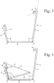
- Fig. 3 shows the housing 2 separately from the other lighting assembly components.
- the housing walls of the housing 2 are arranged in an installation position relative to each other, i.e. the first housing wall 21 is in a first installation position relative to the second housing wall 22, and the second housing wall 22 is in a second installation position relative to the third housing wall 23.
- the first installation position of the first housing wall 21 and the second installation position of the second housing wall 22 are configured for installation of the holder 4 in the housing 2 and for removal of the holder 4 from the housing 2.
- a first installation angle ⁇ 1 of 105° is provided between the first housing wall plane and the second housing wall plane. In alternative embodiments the first installation angle is at least 10° larger than the first operating angle.
- a second installation angle ⁇ 2 of 98° is provided between the second housing wall plane and the third housing wall plane. In alternative embodiments the second installation angle is at least 30° larger than the second operating angle.
- the housing 2 is arranged to be such that if the angle between the first housing wall plane and the second housing wall plane is deflected from the first installation angle ⁇ 1 , the angle between the first housing wall plane and the second housing wall plane will tend to return to the first installation angle ⁇ 1 . Further, the housing 2 is arranged to be such that if the angle between the second housing wall plane and the third housing wall plane is deflected from the second installation angle ⁇ 2 , the angle between the second housing wall plane and the third housing wall plane will tend to return to the second installation angle ⁇ 2 . The housing 2 tends to return to the position according to Fig. 3 , because the housing 2 has been formed by extrusion in that position.
- Fig. 4 shows the housing 2 in which the housing walls are arranged in the installation position relative to each other, and which is provided with the holder 4.
- the housing 2 comprises a retainer projection 215 extending from the free edge of the first housing wall 21 so as to form a retaining recess between the first housing wall 21 and the retainer projection 215, the retaining recess arranged to receive a free edge of the first holder wall 41 for keeping the first holder wall 41 in place relative to the housing 2.
- the free edge of the first holder wall 41 has been received in said retaining recess.
- the retainer projection 215 is arranged to be such that when the housing walls 21, 22 and 23 are arranged in the installation position relative to each other, the holder 4 may be placed inside the housing 2 through the opening between the first housing wall 21 and the third housing wall 23, the installation direction being substantially perpendicular to the longitudinal direction.
- the angle between the first housing wall plane and the second housing wall plane does not tend to return to the first installation angle
- the angle between the second housing wall plane and the third housing wall plane does not tend to return to the second installation angle
- the first flexible hinge is arranged to allow the first housing wall to be pivoted relative to the second housing wall to the first installation position
- the second flexible hinge is arranged to allow the second housing wall to be pivoted relative to the third housing wall to the second installation position.
- the first installation position and the second installation position are arranged to facilitate the installation of the holder in the housing and the removal of the holder from the housing.
- the third holder wall 43 is located at one end of the housing 2 as seen in the longitudinal direction, and the fourth holder wall 44 is located at the other end of the housing 2 as seen in the longitudinal direction.
- the third holder wall 43 and the fourth holder wall 44 are arranged to protect the lighting element 6 by preventing the passage of dirt into the housing 2 from its ends.
- the third holder wall 43 defines a third holder wall plane
- the fourth holder wall 44 defines a fourth holder wall plane. Both of the third holder wall plane and the fourth holder wall plane are substantially perpendicular to the longitudinal direction. In alternative embodiments the third holder wall plane and the fourth holder wall plane are arranged at an angle of over 45° to the longitudinal direction.
- the lighting assembly of Fig. 1 comprises two fastening elements 9, each protruding from the second housing wall 22, and being arranged for fastening of the lighting assembly to a wall of an object to be illuminated.
- the fastening elements 9 are formed in the lighting element 6, i.e. they extend through both of the second holder wall 42 and the second housing wall 22.
- the third housing wall of the housing may be shaped so as to direct light emitted by the lighting element out from the housing in such a way that the lighting pattern from the lighting assembly will have a desired shape.
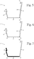
- Fig. 5 shows a modification of the housing of Fig. 3 , in which the third housing wall 23 comprises optical prisms 236 which are arranged to direct light emitted by the lighting element out from the housing.
- Fig. 6 shows a modification of the housing of Fig. 3 , in which the third housing wall 23 comprises a lens 238 which is arranged to direct light emitted by the lighting element out from the housing.
- Both of the optical prisms 236 of Fig. 5 and the lens 238 of Fig. 6 are manufactured from the same material and in the same extrusion process as the third housing wall 23. Apart from the optical prisms 236 and the lens 238, the housings of Fig. 5 and 6 are similar to the housing 2 of Fig. 3 .
- the housing 2 of Fig. 3 is manufactured in one extrusion process from plastic material. All parts of the housing 2 are the same material. In alternative embodiments of the invention the housing is manufactured in a co-extrusion process, such that the housing comprises two or more materials.
- Fig. 7 shows a modification of the housing of Fig. 3 , which has been manufactured from two different materials in one co-extrusion process, such that the material of the third housing wall 23" is translucent, and the material of the first housing wall 21" and the second housing wall 22" is opaque. Both of the materials of the housing 2" are flexible materials. Apart from the materials, the housing 2" of Fig. 7 is similar to the housing 2 of Fig. 3 .
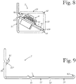
- Fig. 8 shows a cross-section of a lighting assembly according to an alternative embodiment of the invention, comprising a housing 2' and a lighting element 6'.
- the viewing direction of Fig. 8 is parallel to the longitudinal direction.
- Fig. 9 shows the housing 2' of the lighting assembly of Fig. 8 with housing walls arranged in an installation position relative to each other.
- the lighting assembly of Fig. 8 differs from the lighting assembly of Fig. 1 in that the first housing wall 21' is not a substantially planar wall, but has a substantially L-shaped cross-section. Further, the lighting assembly of Fig. 8 does not comprise the holder 4, but the lighting element 6' is directly supported against the internal walls of the housing 2'.
- the internal surface of the first housing wall 21' is provided with a first installation recess 217' which is arranged to receive part of the lighting element 6' for keeping the lighting element 6' in place relative to the housing 2'.
- a second installation recess 218' is provided at the boundary between the first housing wall 21' and the second housing wall 22' and arranged to receive another part of the lighting element 6' for keeping the lighting element 6' in place relative to the housing 2'.
- a first edge of the circuit card 62' has been received in the first installation recess 217'
- a second edge of the circuit card 62' has been received in the second installation recess 218'.
- the several LEDs 61' of the lighting element 6' are installed on the circuit card 62'.
Landscapes
- Engineering & Computer Science (AREA)
- General Engineering & Computer Science (AREA)
- Microelectronics & Electronic Packaging (AREA)
- Power Engineering (AREA)
- Non-Portable Lighting Devices Or Systems Thereof (AREA)
Applications Claiming Priority (1)
| Application Number | Priority Date | Filing Date | Title |
|---|---|---|---|
| FI20185054A FI128286B (fi) | 2018-01-22 | 2018-01-22 | Valaisinkokoonpano |
Publications (2)
| Publication Number | Publication Date |
|---|---|
| EP3514449A1 true EP3514449A1 (de) | 2019-07-24 |
| EP3514449B1 EP3514449B1 (de) | 2020-09-23 |
Family
ID=65036683
Family Applications (1)
| Application Number | Title | Priority Date | Filing Date |
|---|---|---|---|
| EP19152315.8A Active EP3514449B1 (de) | 2018-01-22 | 2019-01-17 | Beleuchtungsanordnung |
Country Status (4)
| Country | Link |
|---|---|
| US (1) | US10571098B2 (de) |
| EP (1) | EP3514449B1 (de) |
| ES (1) | ES2834383T3 (de) |
| FI (1) | FI128286B (de) |
Cited By (2)
| Publication number | Priority date | Publication date | Assignee | Title |
|---|---|---|---|---|
| EP4345368A1 (de) * | 2022-09-28 | 2024-04-03 | Zumtobel Lighting GmbH | Abdeckung für eine lichtemittierende anordnung |
| AT18326U1 (de) * | 2020-10-12 | 2024-10-15 | Zumtobel Lighting Gmbh At | Verschliessbare Linearleuchte |
Citations (2)
| Publication number | Priority date | Publication date | Assignee | Title |
|---|---|---|---|---|
| US6088967A (en) * | 1998-01-02 | 2000-07-18 | Johnson; Wayne A | Closing string light display box |
| US20140268736A1 (en) * | 2013-03-12 | 2014-09-18 | Hafele America Co. | Extruded housing with hinged lens for leds |
Family Cites Families (2)
| Publication number | Priority date | Publication date | Assignee | Title |
|---|---|---|---|---|
| WO2008134424A2 (en) | 2007-04-24 | 2008-11-06 | Lumination Llc | Led perimeter lighting system |
| US20110261566A1 (en) * | 2009-10-26 | 2011-10-27 | Robert Scott Boulton | Exterior lighting system |
-
2018
- 2018-01-22 FI FI20185054A patent/FI128286B/fi active IP Right Grant
-
2019
- 2019-01-17 ES ES19152315T patent/ES2834383T3/es active Active
- 2019-01-17 EP EP19152315.8A patent/EP3514449B1/de active Active
- 2019-01-18 US US16/251,504 patent/US10571098B2/en active Active
Patent Citations (2)
| Publication number | Priority date | Publication date | Assignee | Title |
|---|---|---|---|---|
| US6088967A (en) * | 1998-01-02 | 2000-07-18 | Johnson; Wayne A | Closing string light display box |
| US20140268736A1 (en) * | 2013-03-12 | 2014-09-18 | Hafele America Co. | Extruded housing with hinged lens for leds |
Cited By (3)
| Publication number | Priority date | Publication date | Assignee | Title |
|---|---|---|---|---|
| AT18326U1 (de) * | 2020-10-12 | 2024-10-15 | Zumtobel Lighting Gmbh At | Verschliessbare Linearleuchte |
| EP4345368A1 (de) * | 2022-09-28 | 2024-04-03 | Zumtobel Lighting GmbH | Abdeckung für eine lichtemittierende anordnung |
| WO2024068718A1 (en) * | 2022-09-28 | 2024-04-04 | Zumtobel Lighting Gmbh | Cover for a light emitting assembly |
Also Published As
| Publication number | Publication date |
|---|---|
| FI20185054A1 (fi) | 2019-07-23 |
| US20190226662A1 (en) | 2019-07-25 |
| US10571098B2 (en) | 2020-02-25 |
| FI128286B (fi) | 2020-02-28 |
| EP3514449B1 (de) | 2020-09-23 |
| ES2834383T3 (es) | 2021-06-17 |
Similar Documents
| Publication | Publication Date | Title |
|---|---|---|
| US7857495B2 (en) | Vehicle lighting system including a light guiding member | |
| WO2009110476A1 (ja) | 照明装置 | |
| US8579484B2 (en) | Vehicle lighting device | |
| EP2557357A2 (de) | Fahrzeugbeleuchtungsvorrichtung | |
| US6612718B1 (en) | Optical flange for maintaining luminaire performance and smoothly coupling a lens to a reflector for enclosed luminaires | |
| US10571098B2 (en) | Lighting assembly | |
| JP6311884B2 (ja) | 照明装置 | |
| JP6951342B2 (ja) | 車両用灯具 | |
| JP2015115205A (ja) | 車両用複合ランプ | |
| US11752927B2 (en) | External cladding component of or for a vehicle and vehicle comprising such an external cladding component | |
| US10391932B2 (en) | Illumination unit | |
| JP6579327B2 (ja) | 照明装置 | |
| JP5810322B2 (ja) | ミラーキャビネット | |
| US10816188B2 (en) | Cabinet light for the illumination of a cabinet interior | |
| US20200317121A1 (en) | Vehicle interior lamp | |
| US20050168617A1 (en) | Cover for a monitoring camera | |
| US8770786B2 (en) | Illuminating device with light guiding frame | |
| JP7419833B2 (ja) | 車両用灯具のインナーレンズ、車両用灯具 | |
| JP7356586B2 (ja) | 車両用ドアミラー | |
| JP7388869B2 (ja) | 電気機器 | |
| JP7547092B2 (ja) | 照明装置 | |
| JP2015027544A (ja) | ミラーキャビネット | |
| GB2580433A (en) | Illuminated vehicle window | |
| JP2016157541A (ja) | 車両用灯具 | |
| EP3858674A1 (de) | Lampenanordnung für ein fahrzeug |
Legal Events
| Date | Code | Title | Description |
|---|---|---|---|
| PUAI | Public reference made under article 153(3) epc to a published international application that has entered the european phase |
Free format text: ORIGINAL CODE: 0009012 |
|
| STAA | Information on the status of an ep patent application or granted ep patent |
Free format text: STATUS: THE APPLICATION HAS BEEN PUBLISHED |
|
| AK | Designated contracting states |
Kind code of ref document: A1 Designated state(s): AL AT BE BG CH CY CZ DE DK EE ES FI FR GB GR HR HU IE IS IT LI LT LU LV MC MK MT NL NO PL PT RO RS SE SI SK SM TR |
|
| AX | Request for extension of the european patent |
Extension state: BA ME |
|
| STAA | Information on the status of an ep patent application or granted ep patent |
Free format text: STATUS: REQUEST FOR EXAMINATION WAS MADE |
|
| 17P | Request for examination filed |
Effective date: 20190815 |
|
| RBV | Designated contracting states (corrected) |
Designated state(s): AL AT BE BG CH CY CZ DE DK EE ES FI FR GB GR HR HU IE IS IT LI LT LU LV MC MK MT NL NO PL PT RO RS SE SI SK SM TR |
|
| STAA | Information on the status of an ep patent application or granted ep patent |
Free format text: STATUS: EXAMINATION IS IN PROGRESS |
|
| 17Q | First examination report despatched |
Effective date: 20191119 |
|
| GRAP | Despatch of communication of intention to grant a patent |
Free format text: ORIGINAL CODE: EPIDOSNIGR1 |
|
| STAA | Information on the status of an ep patent application or granted ep patent |
Free format text: STATUS: GRANT OF PATENT IS INTENDED |
|
| RIC1 | Information provided on ipc code assigned before grant |
Ipc: F21V 17/16 20060101ALI20200428BHEP Ipc: F21V 15/01 20060101AFI20200428BHEP Ipc: F21Y 115/10 20160101ALN20200428BHEP Ipc: F21S 4/28 20160101ALI20200428BHEP Ipc: F21Y 103/10 20160101ALN20200428BHEP |
|
| INTG | Intention to grant announced |
Effective date: 20200528 |
|
| GRAS | Grant fee paid |
Free format text: ORIGINAL CODE: EPIDOSNIGR3 |
|
| GRAA | (expected) grant |
Free format text: ORIGINAL CODE: 0009210 |
|
| STAA | Information on the status of an ep patent application or granted ep patent |
Free format text: STATUS: THE PATENT HAS BEEN GRANTED |
|
| AK | Designated contracting states |
Kind code of ref document: B1 Designated state(s): AL AT BE BG CH CY CZ DE DK EE ES FI FR GB GR HR HU IE IS IT LI LT LU LV MC MK MT NL NO PL PT RO RS SE SI SK SM TR |
|
| REG | Reference to a national code |
Ref country code: GB Ref legal event code: FG4D |
|
| REG | Reference to a national code |
Ref country code: CH Ref legal event code: EP |
|
| REG | Reference to a national code |
Ref country code: IE Ref legal event code: FG4D |
|
| REG | Reference to a national code |
Ref country code: DE Ref legal event code: R096 Ref document number: 602019000713 Country of ref document: DE Ref country code: AT Ref legal event code: REF Ref document number: 1316754 Country of ref document: AT Kind code of ref document: T Effective date: 20201015 |
|
| PG25 | Lapsed in a contracting state [announced via postgrant information from national office to epo] |
Ref country code: FI Free format text: LAPSE BECAUSE OF FAILURE TO SUBMIT A TRANSLATION OF THE DESCRIPTION OR TO PAY THE FEE WITHIN THE PRESCRIBED TIME-LIMIT Effective date: 20200923 Ref country code: HR Free format text: LAPSE BECAUSE OF FAILURE TO SUBMIT A TRANSLATION OF THE DESCRIPTION OR TO PAY THE FEE WITHIN THE PRESCRIBED TIME-LIMIT Effective date: 20200923 Ref country code: BG Free format text: LAPSE BECAUSE OF FAILURE TO SUBMIT A TRANSLATION OF THE DESCRIPTION OR TO PAY THE FEE WITHIN THE PRESCRIBED TIME-LIMIT Effective date: 20201223 Ref country code: SE Free format text: LAPSE BECAUSE OF FAILURE TO SUBMIT A TRANSLATION OF THE DESCRIPTION OR TO PAY THE FEE WITHIN THE PRESCRIBED TIME-LIMIT Effective date: 20200923 Ref country code: NO Free format text: LAPSE BECAUSE OF FAILURE TO SUBMIT A TRANSLATION OF THE DESCRIPTION OR TO PAY THE FEE WITHIN THE PRESCRIBED TIME-LIMIT Effective date: 20201223 Ref country code: GR Free format text: LAPSE BECAUSE OF FAILURE TO SUBMIT A TRANSLATION OF THE DESCRIPTION OR TO PAY THE FEE WITHIN THE PRESCRIBED TIME-LIMIT Effective date: 20201224 |
|
| REG | Reference to a national code |
Ref country code: AT Ref legal event code: MK05 Ref document number: 1316754 Country of ref document: AT Kind code of ref document: T Effective date: 20200923 |
|
| PG25 | Lapsed in a contracting state [announced via postgrant information from national office to epo] |
Ref country code: RS Free format text: LAPSE BECAUSE OF FAILURE TO SUBMIT A TRANSLATION OF THE DESCRIPTION OR TO PAY THE FEE WITHIN THE PRESCRIBED TIME-LIMIT Effective date: 20200923 Ref country code: LV Free format text: LAPSE BECAUSE OF FAILURE TO SUBMIT A TRANSLATION OF THE DESCRIPTION OR TO PAY THE FEE WITHIN THE PRESCRIBED TIME-LIMIT Effective date: 20200923 |
|
| REG | Reference to a national code |
Ref country code: NL Ref legal event code: MP Effective date: 20200923 |
|
| REG | Reference to a national code |
Ref country code: LT Ref legal event code: MG4D |
|
| PG25 | Lapsed in a contracting state [announced via postgrant information from national office to epo] |
Ref country code: SM Free format text: LAPSE BECAUSE OF FAILURE TO SUBMIT A TRANSLATION OF THE DESCRIPTION OR TO PAY THE FEE WITHIN THE PRESCRIBED TIME-LIMIT Effective date: 20200923 Ref country code: LT Free format text: LAPSE BECAUSE OF FAILURE TO SUBMIT A TRANSLATION OF THE DESCRIPTION OR TO PAY THE FEE WITHIN THE PRESCRIBED TIME-LIMIT Effective date: 20200923 Ref country code: CZ Free format text: LAPSE BECAUSE OF FAILURE TO SUBMIT A TRANSLATION OF THE DESCRIPTION OR TO PAY THE FEE WITHIN THE PRESCRIBED TIME-LIMIT Effective date: 20200923 Ref country code: RO Free format text: LAPSE BECAUSE OF FAILURE TO SUBMIT A TRANSLATION OF THE DESCRIPTION OR TO PAY THE FEE WITHIN THE PRESCRIBED TIME-LIMIT Effective date: 20200923 Ref country code: PT Free format text: LAPSE BECAUSE OF FAILURE TO SUBMIT A TRANSLATION OF THE DESCRIPTION OR TO PAY THE FEE WITHIN THE PRESCRIBED TIME-LIMIT Effective date: 20210125 Ref country code: EE Free format text: LAPSE BECAUSE OF FAILURE TO SUBMIT A TRANSLATION OF THE DESCRIPTION OR TO PAY THE FEE WITHIN THE PRESCRIBED TIME-LIMIT Effective date: 20200923 |
|
| PG25 | Lapsed in a contracting state [announced via postgrant information from national office to epo] |
Ref country code: AL Free format text: LAPSE BECAUSE OF FAILURE TO SUBMIT A TRANSLATION OF THE DESCRIPTION OR TO PAY THE FEE WITHIN THE PRESCRIBED TIME-LIMIT Effective date: 20200923 Ref country code: AT Free format text: LAPSE BECAUSE OF FAILURE TO SUBMIT A TRANSLATION OF THE DESCRIPTION OR TO PAY THE FEE WITHIN THE PRESCRIBED TIME-LIMIT Effective date: 20200923 Ref country code: PL Free format text: LAPSE BECAUSE OF FAILURE TO SUBMIT A TRANSLATION OF THE DESCRIPTION OR TO PAY THE FEE WITHIN THE PRESCRIBED TIME-LIMIT Effective date: 20200923 Ref country code: IS Free format text: LAPSE BECAUSE OF FAILURE TO SUBMIT A TRANSLATION OF THE DESCRIPTION OR TO PAY THE FEE WITHIN THE PRESCRIBED TIME-LIMIT Effective date: 20210123 |
|
| REG | Reference to a national code |
Ref country code: ES Ref legal event code: FG2A Ref document number: 2834383 Country of ref document: ES Kind code of ref document: T3 Effective date: 20210617 |
|
| REG | Reference to a national code |
Ref country code: DE Ref legal event code: R097 Ref document number: 602019000713 Country of ref document: DE |
|
| PG25 | Lapsed in a contracting state [announced via postgrant information from national office to epo] |
Ref country code: SK Free format text: LAPSE BECAUSE OF FAILURE TO SUBMIT A TRANSLATION OF THE DESCRIPTION OR TO PAY THE FEE WITHIN THE PRESCRIBED TIME-LIMIT Effective date: 20200923 |
|
| PLBE | No opposition filed within time limit |
Free format text: ORIGINAL CODE: 0009261 |
|
| STAA | Information on the status of an ep patent application or granted ep patent |
Free format text: STATUS: NO OPPOSITION FILED WITHIN TIME LIMIT |
|
| PG25 | Lapsed in a contracting state [announced via postgrant information from national office to epo] |
Ref country code: MC Free format text: LAPSE BECAUSE OF FAILURE TO SUBMIT A TRANSLATION OF THE DESCRIPTION OR TO PAY THE FEE WITHIN THE PRESCRIBED TIME-LIMIT Effective date: 20200923 Ref country code: DK Free format text: LAPSE BECAUSE OF FAILURE TO SUBMIT A TRANSLATION OF THE DESCRIPTION OR TO PAY THE FEE WITHIN THE PRESCRIBED TIME-LIMIT Effective date: 20200923 Ref country code: SI Free format text: LAPSE BECAUSE OF FAILURE TO SUBMIT A TRANSLATION OF THE DESCRIPTION OR TO PAY THE FEE WITHIN THE PRESCRIBED TIME-LIMIT Effective date: 20200923 |
|
| 26N | No opposition filed |
Effective date: 20210624 |
|
| PG25 | Lapsed in a contracting state [announced via postgrant information from national office to epo] |
Ref country code: LU Free format text: LAPSE BECAUSE OF NON-PAYMENT OF DUE FEES Effective date: 20210117 |
|
| REG | Reference to a national code |
Ref country code: BE Ref legal event code: MM Effective date: 20210131 |
|
| PG25 | Lapsed in a contracting state [announced via postgrant information from national office to epo] |
Ref country code: IT Free format text: LAPSE BECAUSE OF FAILURE TO SUBMIT A TRANSLATION OF THE DESCRIPTION OR TO PAY THE FEE WITHIN THE PRESCRIBED TIME-LIMIT Effective date: 20200923 |
|
| PG25 | Lapsed in a contracting state [announced via postgrant information from national office to epo] |
Ref country code: IE Free format text: LAPSE BECAUSE OF NON-PAYMENT OF DUE FEES Effective date: 20210117 |
|
| PG25 | Lapsed in a contracting state [announced via postgrant information from national office to epo] |
Ref country code: BE Free format text: LAPSE BECAUSE OF NON-PAYMENT OF DUE FEES Effective date: 20210131 |
|
| REG | Reference to a national code |
Ref country code: CH Ref legal event code: PL |
|
| PG25 | Lapsed in a contracting state [announced via postgrant information from national office to epo] |
Ref country code: LI Free format text: LAPSE BECAUSE OF NON-PAYMENT OF DUE FEES Effective date: 20220131 Ref country code: CH Free format text: LAPSE BECAUSE OF NON-PAYMENT OF DUE FEES Effective date: 20220131 |
|
| PG25 | Lapsed in a contracting state [announced via postgrant information from national office to epo] |
Ref country code: NL Free format text: LAPSE BECAUSE OF NON-PAYMENT OF DUE FEES Effective date: 20200923 Ref country code: CY Free format text: LAPSE BECAUSE OF FAILURE TO SUBMIT A TRANSLATION OF THE DESCRIPTION OR TO PAY THE FEE WITHIN THE PRESCRIBED TIME-LIMIT Effective date: 20200923 |
|
| PG25 | Lapsed in a contracting state [announced via postgrant information from national office to epo] |
Ref country code: HU Free format text: LAPSE BECAUSE OF FAILURE TO SUBMIT A TRANSLATION OF THE DESCRIPTION OR TO PAY THE FEE WITHIN THE PRESCRIBED TIME-LIMIT; INVALID AB INITIO Effective date: 20190117 |
|
| PG25 | Lapsed in a contracting state [announced via postgrant information from national office to epo] |
Ref country code: MK Free format text: LAPSE BECAUSE OF FAILURE TO SUBMIT A TRANSLATION OF THE DESCRIPTION OR TO PAY THE FEE WITHIN THE PRESCRIBED TIME-LIMIT Effective date: 20200923 |
|
| PG25 | Lapsed in a contracting state [announced via postgrant information from national office to epo] |
Ref country code: TR Free format text: LAPSE BECAUSE OF FAILURE TO SUBMIT A TRANSLATION OF THE DESCRIPTION OR TO PAY THE FEE WITHIN THE PRESCRIBED TIME-LIMIT Effective date: 20200923 |
|
| PG25 | Lapsed in a contracting state [announced via postgrant information from national office to epo] |
Ref country code: MT Free format text: LAPSE BECAUSE OF FAILURE TO SUBMIT A TRANSLATION OF THE DESCRIPTION OR TO PAY THE FEE WITHIN THE PRESCRIBED TIME-LIMIT Effective date: 20200923 |
|
| REG | Reference to a national code |
Ref country code: DE Ref legal event code: R081 Ref document number: 602019000713 Country of ref document: DE Owner name: TEKNOWARE RAIL&ROAD OY, FI Free format text: FORMER OWNER: TEKNOWARE OY, LAHTI, FI |
|
| PGFP | Annual fee paid to national office [announced via postgrant information from national office to epo] |
Ref country code: GB Payment date: 20260127 Year of fee payment: 8 |
|
| PGFP | Annual fee paid to national office [announced via postgrant information from national office to epo] |
Ref country code: ES Payment date: 20260202 Year of fee payment: 8 |
|
| PGFP | Annual fee paid to national office [announced via postgrant information from national office to epo] |
Ref country code: DE Payment date: 20260128 Year of fee payment: 8 |
|
| PGFP | Annual fee paid to national office [announced via postgrant information from national office to epo] |
Ref country code: FR Payment date: 20260126 Year of fee payment: 8 |