EP3514656A1 - Commutateur rotatif d'un appareil électroménager - Google Patents
Commutateur rotatif d'un appareil électroménager Download PDFInfo
- Publication number
- EP3514656A1 EP3514656A1 EP18152925.6A EP18152925A EP3514656A1 EP 3514656 A1 EP3514656 A1 EP 3514656A1 EP 18152925 A EP18152925 A EP 18152925A EP 3514656 A1 EP3514656 A1 EP 3514656A1
- Authority
- EP
- European Patent Office
- Prior art keywords
- rotary handle
- rotary
- rotary switch
- support
- support element
- Prior art date
- Legal status (The legal status is an assumption and is not a legal conclusion. Google has not performed a legal analysis and makes no representation as to the accuracy of the status listed.)
- Withdrawn
Links
Images

Classifications
-
- G—PHYSICS
- G05—CONTROLLING; REGULATING
- G05G—CONTROL DEVICES OR SYSTEMS INSOFAR AS CHARACTERISED BY MECHANICAL FEATURES ONLY
- G05G1/00—Controlling members, e.g. knobs or handles; Assemblies or arrangements thereof; Indicating position of controlling members
- G05G1/08—Controlling members for hand actuation by rotary movement, e.g. hand wheels
- G05G1/087—Controlling members for hand actuation by rotary movement, e.g. hand wheels retractable; Flush control knobs
Definitions
- the invention is directed to a rotary switch of a household electrical appliance for installation in an opening of a device wall of the household appliance, with a rotary handle having a cylindrical wall and which is movable in the direction of a longitudinal axis of the rotary switch between a lowered position and an operating position, a sleeve-like sliding element, which is rotatably connected to the rotary handle, and a switching or actuator of the household appliance coupled carrier element, which is slidably received in the sleeve-like sliding element, wherein the rotary handle has a handling portion which extends in the direction of the longitudinal axis and in the operating position for handling an operator from the device wall of the household appliance can be arranged protruding.
- Rotary switches for household electrical appliances are known in various configurations.
- a rotary handle is arranged movable relative to a device wall of the household appliance and by a rotational movement of the rotary handle an operating setting of the household appliance is feasible.
- Such rotary switches are also known as rotary knobs, there are versions in which the rotary handle can be lowered in the axial direction and thus in the direction of the longitudinal axis of the rotary switch.
- Such rotary switches can be moved by a rotational movement in various switching positions and are used, for example, in an electric stove for switching on a hotplate, the rotary handle after operation can be moved to a lowered position to protect it from damage or contamination when the household appliance is not more is used.
- a rotary switch of the type mentioned is for example from the DE 20 2009 018 510 U1 known.
- This known rotary switch has the disadvantage that due to manufacturing tolerances and the play between the movable components of the rotary switch, the rotary handle is not fixed in its operating position, but is movable in the circumferential direction in its handling, which gives the operator the impression of a wobbly and unstable Rotary handle generated.
- the invention has for its object to provide a solution that provides an improved rotary switch in a structurally simple manner in which the overall visual impression over the entire service life is improved and which has a fixed seat in the operating position.
- the object is achieved in that the rotary handle has a support portion which extends in the direction of the longitudinal axis and on which at least one support element is formed, extending in a radial direction from the cylindrical wall of the rotary handle extends and which can be supported in the radial direction at the opening of the device wall.
- the invention provides a rotary switch is provided in a structurally simple manner and cost, in which the rotary handle in its operating position wobble-free is arranged by the at least one support member is supported in the radial direction, so that a movement of the rotary handle is prevented in a radial direction according to the invention.
- the at least one support element can either directly inside on the opening of the device wall of the household electrical appliance or on an element which is used as a design part in the opening of the device wall of the electrical household appliance support.
- the often criticized crescent moon which corresponds to a non-uniform, circumferential slit image around the turning handle around, no longer exists.
- the at least one support element is formed with a wedge surface which is formed rising in a Ausstellcardi of the rotary handle.
- a wedge surface is particularly suitable if the at least one support element only comes into contact with the operating position during its movement from the lowered position into the operating position, for example, the opening of the device wall, so that tilting of the at least one support element in the movement of the rotary handle in the operating position is prevented.
- the at least one support element is formed with a movement surface, which is formed rising in a direction opposite to a Ausstellcardi the rotary handle.
- the at least one support element consequently does not extend abruptly in the radial direction, but rather with an ascending movement surface.
- the rising trained movement area offers the possibility that the rotary handle can also be replaced by a new rotary handle when the rotary switch according to the invention is installed on the appliance.
- the invention sees in further Embodiment before that the at least one support element is formed elastically deformable. As a result, a play-free concern of the at least one support element is ensured at the opening of the device wall of the household appliance or on a design element fastened in the opening.
- the elastic property of the at least one support element can be realized either by a suitable choice of material or in that the at least one support element is formed between two incisions which are formed in the wall of the rotary handle and extending from a longitudinal end of the rotary handle in the direction of Extend longitudinal axis.
- the invention provides in a further embodiment that the at least one support element has a radial extent which is between 30% and 50% of the thickness of the wall.
- Particularly useful in an embodiment of the invention is when at least three support elements are formed, which are uniformly spaced from each other with respect to a circumferential direction of the rotary switch are formed on the rotary handle. As a result, a uniform slit image is realized at the same time stable and wobble-free arrangement of the rotary handle in the operating position.
- a shake-free of the arranged in its operating position rotary handle can also be realized with a single support element when extending at least one support member in a circumferential direction of the rotary switch by more than 180 ° around the rotary handle.
- the support element may be a design element of the household appliance, which increases the visual impression and covers the opening in the device wall of the household appliance. Accordingly, it is provided in an embodiment of the invention that the support element is pot-shaped or annular.
- the cup-like design may additionally be a protective sleeve in which the movement mechanism of the rotary switch, which is formed by the carrier element and the sliding element, is concealed and protected.
- the invention provides in an embodiment that the rotary handle is designed to be rotatable about the longitudinal axis at least in the operating position. By adjusting the rotary handle different operating states of the household appliance can be adjusted.
- the carrier element has a slide control for guiding the movement of the sliding element on the carrier element.
- the link control comprises a groove track formed in the carrier element and a linkage coupling the sliding element and the carrier element.
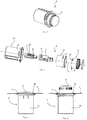
- FIGS. 1 to 4 show a retractable rotary switch 1 for setting behind a device wall 2 of a household appliance arranged switching and / or actuators in household appliances, such as stoves, washing machines, dishwashers or the like.
- the rotary switch 1 is inserted into an opening 3 in the device wall 2 and comprises a rotary handle 4, which may have an adjustment scale, not shown in the figures, and is rotatably connected to a sliding element 5 or plugged together with this.
- a rotary handle 4 integrally with the sliding element 5, wherein it is preferred for reasons of the manufacturing process to couple the rotary handle 4 by means of a coupling means with the sliding element 5 in the manner of a plug connection.
- the rotary switch 1 further comprises a switchable with a switching or actuator of the household appliance support member 6, wherein the sliding member 5 against the force of a coil spring formed as a return element, which is not shown in the figures, in the direction of a longitudinal axis 7 of the rotary switch 1 is movable ,
- the rotary handle 3, the sliding element 4 and the carrier element 5 may be formed as plastic injection molded parts.
- the cap-like rotary handle 4 which has a cylindrical wall 8, is in the form of a handle and against the restoring force of the return element, which may be a compression spring, between a lowered position, in which the rotary handle 4 is sunk in the device wall 2 of the household appliance or flush with this (see for example FIG. 3 ), and an operating position in which the rotary handle 4 protrudes from the device wall 2 of the household appliance (see, for example FIG. 4 ), movable.
- the return element which may be a compression spring
- the sliding element 5 is formed in the manner of a sleeve with a cavity, so that in the sliding movement between the operating position and the lowered position of the fixed with the Sliding element 5 connected rotary handle 4 on the carrier element 6 against the restoring force of the return element in the direction of the longitudinal axis 7 of the rotary switch 1 is moved.
- the support member 6 has at its end remote from the rotary handle 4 on a coupling means to the rotary switch 1 with behind the switch panel 2 arranged switching or actuators of the household appliance, which are not shown in the figures, to couple.
- the connection between the coupling agent and the switching or actuators can be executed positively and / or non-positively, with known plug-in, Verrast- and / or locking connections can be considered.
- the switching or setting by the rotary switch 1 takes place by turning the rotary handle 3 about the longitudinal axis 7.
- the rotary switch 1 at least in the operating position, ie in the disengaged position, about the longitudinal axis 7 rotatable.
- the rotary switch 1 additionally in the lowered position, in which the cap-shaped rotary handle 3 is flush with the switch panel 2, about the longitudinal axis 7 is rotatable.
- the movement or the displacement movement from the in FIG. 4 shown operating position in the in FIG. 3
- the sliding handle 5 connected to the rotary handle 4 slides in this movement on the stationary fixed to the household appliance support member 6.
- the rotary handle 4 is pressed in the sliding movement from the operating position in the lowered position known about the actual sinking position addition , whereby a locking of the rotary handle 4 in the lowered position takes place.
- the sliding movement from the lowered position into the operating position also takes place by pressing the rotary handle 4 on the actual lowered position, whereby the locking of the rotary handle 3 is released and the restoring force of the return element connected to the sliding element 5 rotary handle 4 on the support member 5 in the direction of Operating position moves.
- the displacement movement between the lowered position and the operating position by means of a known gate control 9, which is formed in the lateral surface of the support member 6.
- the slide control 9 is a sliding movement on the type of the known from the pen principle of the latch possible, the slide control 9 also serves to guide the sliding movement of the sliding element 5 on the support member 6.
- the slide control 9 comprises a formed in the lateral surface of the support member 6 groove track 10 and a movable in the groove track 10 and guided in this backdrop 11, which in FIG. 2 hidden within the sliding element 5 is arranged and which couples the movement of the sliding element 5 and support member 6 in a known manner.
- the rotary handle 4 has a handling portion 12 (see, for example FIG. 10 which extends in the direction of the longitudinal axis 7 and which can be arranged projecting in the operating position for handling by an operator from the device wall 2 of the household appliance.
- the rotary switch 1 may optionally include a housing 14 and a support member 15, as shown in the actual embodiment of the figures, so that the rotary switch 1 can be supplied as a complete unit.
- the housing 14 is installed behind the device wall 2 in the household appliance, whereas the support member 15 may be formed as a design element, which is adapted to the visual appearance of the household appliance and the opening 3 of the device wall 2 covered with its edge from the outside.
- the support member 15 can be inserted from the outside into the opening 3 and latched to the housing 14, 14 slots 16 are formed for this purpose in the wall of the housing into which corresponding latching hooks 17 can engage, the outside of the wall of the support member 15th arranged and molded, as for example FIG. 2 you can see.
- the support member 15 is executed pot-like, with a shorter and annular configuration is conceivable.
- the housing 14 and the support member 15 are optional components and for the rotary switch 1 according to the invention no components that must be present.
- the rotary handle 4 a support portion 18 (see, for example FIG. 10 ) which extends in the direction of the longitudinal axis 7.
- the support portion 18 is not visible from the outside both in the lowered position and in the operating position, wherein for the embodiment shown in the figures on the support portion 18 a plurality of support elements 19 are formed, which will be described below with reference to FIGS FIGS. 5 to 10 be explained in more detail.
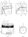
- a total of three support members 19 are formed on the rotary handle 4, which are uniformly spaced from each other with respect to a circumferential direction 20 of the rotary switch 1 formed on the rotary handle 4 (see, for example FIG. 6 ).
- the support elements 19 extend in a radial direction 21 from the cylindrical wall 8 of the rotary handle 4 and serve to support the rotary handle 4 at the opening 3 of the device wall 2 in the radial direction 21.
- the optional support element 15 is arranged within the opening 3 of the device wall 2. Consequently, the support member 15, which is mounted in an installation of the rotary switch 1 in the household appliance in the opening 3 of the device wall 2, circumferentially disposed about the rotary handle 4 around, wherein the support member 15 has a in the direction of the longitudinal axis 7 extending support surface 22 ( see for example FIG. 5 ).
- the rotary handle 4 moves with its handling portion 12 in its movement between the lowered position and the operating position by the support member 15 at least partially therethrough, wherein at least in the operating position, the support member 19 Rotary handle 4 supporting the inside of the support surface 22 of the support member 15 in the radial direction 21 are arranged adjacent, as it is in FIG. 5 is shown.
- the rotary handle 4 is arranged wobble-free and centered in its operating position and the movement can be done easily from the lowered position into the operating position, the support elements 19 are formed elastically deformable. This can be achieved either by a suitable choice of material for the support elements 19 or by the measure that a respective support member 19 between two cuts 23 and 24 is arranged.
- the notches 23, 24 are formed in the cylindrical wall 8 of the rotary handle 4 and extend from a longitudinal end 25 of the rotary handle 4 in the direction of the longitudinal axis 7, as for example in FIG. 7 is shown. Through the notches 23, 24 a respective support member 19 is formed in the manner of a spring tongue, which is formed elastically yielding in the radial direction 21.
- the two incisions 23, 24 with a greater extension 26 in the direction of the longitudinal axis 7 than the extension 27 in the direction of the longitudinal axis 7 of a respective support member 19, as it FIG. 10 shows.
- the respective support elements 19 also have a radial extension 28, which is between 30% and 50% of the thickness 29 of the cylindrical wall 8 (see FIG. 9 ).
- a respective support member 19 is formed with a wedge surface 30, which in a Ausstellcardi 31 of the rotary handle 4, ie in the direction in which the rotary handle 4 in its movement is moved from the lowered position into the operating position, is formed rising.
- a support portion 33 is arranged, with which a respective support member 19 is supported in the radial direction 21 on the support surface 22 and at the opening 3 to ensure the freedom of rotation of the rotary handle 4 and the rotary handle 4 in the opening 3 to center.
- the wedge surface 30, the support portion 33 and the movement surface 32 is arranged.
- FIG. 11 an alternative embodiment of the invention is shown, wherein in this alternative, only a single support member 19 is formed on the rotary handle 4.
- the one support member 19 extends thereby by more than 180 ° in the circumferential direction 20 extends around the rotary handle 4. This circumferential extent is sufficient to support the rotary handle 4 wobble-free in the operating position.
Landscapes
- Physics & Mathematics (AREA)
- General Physics & Mathematics (AREA)
- Engineering & Computer Science (AREA)
- Automation & Control Theory (AREA)
- Switches With Compound Operations (AREA)
- Rotary Switch, Piano Key Switch, And Lever Switch (AREA)
Priority Applications (1)
| Application Number | Priority Date | Filing Date | Title |
|---|---|---|---|
| EP18152925.6A EP3514656A1 (fr) | 2018-01-23 | 2018-01-23 | Commutateur rotatif d'un appareil électroménager |
Applications Claiming Priority (1)
| Application Number | Priority Date | Filing Date | Title |
|---|---|---|---|
| EP18152925.6A EP3514656A1 (fr) | 2018-01-23 | 2018-01-23 | Commutateur rotatif d'un appareil électroménager |
Publications (1)
| Publication Number | Publication Date |
|---|---|
| EP3514656A1 true EP3514656A1 (fr) | 2019-07-24 |
Family
ID=61074310
Family Applications (1)
| Application Number | Title | Priority Date | Filing Date |
|---|---|---|---|
| EP18152925.6A Withdrawn EP3514656A1 (fr) | 2018-01-23 | 2018-01-23 | Commutateur rotatif d'un appareil électroménager |
Country Status (1)
| Country | Link |
|---|---|
| EP (1) | EP3514656A1 (fr) |
Citations (7)
| Publication number | Priority date | Publication date | Assignee | Title |
|---|---|---|---|---|
| US5384442A (en) * | 1993-01-05 | 1995-01-24 | Whirlpool Corporation | Control knob assembly for a cooking appliance |
| DE202009018510U1 (de) | 2009-11-25 | 2011-11-15 | Hurst & Schröder GmbH | Drehschalter für elektrische Haushaltsgeräte |
| EP2410547A1 (fr) * | 2010-07-22 | 2012-01-25 | Miele & Cie. KG | Appareil ménager doté d'une unité de garrot de fonctionnement descendante |
| EP2485111A1 (fr) * | 2011-02-04 | 2012-08-08 | Whirlpool Corporation | Commande rétractable améliorée pour appareil ménager |
| JP2013026028A (ja) * | 2011-07-21 | 2013-02-04 | Calsonic Kansei Corp | ダイヤル型スイッチ装置 |
| DE102012222146A1 (de) * | 2012-12-04 | 2014-06-18 | BSH Bosch und Siemens Hausgeräte GmbH | Bedienelement für ein Haushaltsgerät mit einem Stützelement und einem Führungselement, Bedienvorrichtung mit einem derartigen Bedienelement sowie Haushaltsgerät mit einer Bedienvorrichtung |
| WO2014090511A1 (fr) * | 2012-12-14 | 2014-06-19 | Arcelik Anonim Sirketi | Appareil électroménager comprenant un bouton |
-
2018
- 2018-01-23 EP EP18152925.6A patent/EP3514656A1/fr not_active Withdrawn
Patent Citations (7)
| Publication number | Priority date | Publication date | Assignee | Title |
|---|---|---|---|---|
| US5384442A (en) * | 1993-01-05 | 1995-01-24 | Whirlpool Corporation | Control knob assembly for a cooking appliance |
| DE202009018510U1 (de) | 2009-11-25 | 2011-11-15 | Hurst & Schröder GmbH | Drehschalter für elektrische Haushaltsgeräte |
| EP2410547A1 (fr) * | 2010-07-22 | 2012-01-25 | Miele & Cie. KG | Appareil ménager doté d'une unité de garrot de fonctionnement descendante |
| EP2485111A1 (fr) * | 2011-02-04 | 2012-08-08 | Whirlpool Corporation | Commande rétractable améliorée pour appareil ménager |
| JP2013026028A (ja) * | 2011-07-21 | 2013-02-04 | Calsonic Kansei Corp | ダイヤル型スイッチ装置 |
| DE102012222146A1 (de) * | 2012-12-04 | 2014-06-18 | BSH Bosch und Siemens Hausgeräte GmbH | Bedienelement für ein Haushaltsgerät mit einem Stützelement und einem Führungselement, Bedienvorrichtung mit einem derartigen Bedienelement sowie Haushaltsgerät mit einer Bedienvorrichtung |
| WO2014090511A1 (fr) * | 2012-12-14 | 2014-06-19 | Arcelik Anonim Sirketi | Appareil électroménager comprenant un bouton |
Similar Documents
| Publication | Publication Date | Title |
|---|---|---|
| DE3410047C2 (de) | Permutationsschloß mit Schlüsselgeheimnis-Neueinstellvorrichtung | |
| DE102011084464A1 (de) | Mechanisch sperrbarer Schalter | |
| EP1470624B1 (fr) | Unite enfichable pour un dispositif de connexion dote de contacts de coupure auxiliaires | |
| DE102008020986A1 (de) | Vorrichtung mit einem Unterteil und einer Rückholfeder zur drehbaren Lagerung eines Ausstattungsteils, insbesondere eines Türdrückers | |
| EP1249570B1 (fr) | Dispositif de fermeture | |
| DE102015003337A1 (de) | Anzeige- und/oder Bedienvorrichtung für ein elektronisches Haushaltsgerät | |
| EP3514656A1 (fr) | Commutateur rotatif d'un appareil électroménager | |
| DE2651376C2 (de) | Drucktastenanordnung zur Betätigung mindestens eines Schaltkontaktes eines elektrischen Schalters | |
| EP1480791B1 (fr) | Trancheuse dotee d'une poignee tournante | |
| DE10259605B3 (de) | Elektrischer Kippschalter | |
| DE4323083A1 (de) | Multifunktionsschalter zur Betätigung einer ersten und zweiten elektrischen Einrichtung | |
| EP0973182A2 (fr) | Interrupteur rotatif pour appareil ménager | |
| DE69501990T2 (de) | Drehschalter mit verriegelbarer Position | |
| EP1022102B1 (fr) | Interrupteur, ainsi que moyens de contrôle de la plaque d'écartement d'une machine de coupe | |
| DE102015220001B4 (de) | Zündanlassschalter, Montageeinheit sowie Kraftfahrzeug mit einer solchen Montageeinheit | |
| WO2014139891A1 (fr) | Unité d'entrée pour un élément de commande pouvant être actionné par pression et par rotation | |
| DE102021126433B3 (de) | Installationselement für elektrische Anschlusseinheiten | |
| DE2036736C3 (de) | Elektrischer Schalter mit einem axial verschiebbaren Mitnehmer, in dem ein Schlüssel eingreift | |
| DE102009020141B4 (de) | Vorrichtung zur gegenseitigen Verriegelung zweier Schalter, insbesondere Leistungsschalter | |
| DE102009017059B3 (de) | Anordnung zur Blockierung eines Betätigungselements eines Elektroinstallationsgeräts sowie Elektroinstallationsgerät | |
| DE2462034C3 (de) | Zum Zusammensetzen von Tastaturen geeignete Taste | |
| DE10208491A1 (de) | Allesschneider mit Sicherheitsschalter | |
| EP1858384B1 (fr) | Grille-pain | |
| EP1627398A2 (fr) | Dispositif de commande | |
| DE102005006352A1 (de) | Elektrischer Wasserkocher und Verfahren zur Montage eines kleinen Haushaltsgerätes |
Legal Events
| Date | Code | Title | Description |
|---|---|---|---|
| PUAI | Public reference made under article 153(3) epc to a published international application that has entered the european phase |
Free format text: ORIGINAL CODE: 0009012 |
|
| STAA | Information on the status of an ep patent application or granted ep patent |
Free format text: STATUS: THE APPLICATION HAS BEEN PUBLISHED |
|
| AK | Designated contracting states |
Kind code of ref document: A1 Designated state(s): AL AT BE BG CH CY CZ DE DK EE ES FI FR GB GR HR HU IE IS IT LI LT LU LV MC MK MT NL NO PL PT RO RS SE SI SK SM TR |
|
| AX | Request for extension of the european patent |
Extension state: BA ME |
|
| STAA | Information on the status of an ep patent application or granted ep patent |
Free format text: STATUS: REQUEST FOR EXAMINATION WAS MADE |
|
| 17P | Request for examination filed |
Effective date: 20200124 |
|
| RBV | Designated contracting states (corrected) |
Designated state(s): AL AT BE BG CH CY CZ DE DK EE ES FI FR GB GR HR HU IE IS IT LI LT LU LV MC MK MT NL NO PL PT RO RS SE SI SK SM TR |
|
| STAA | Information on the status of an ep patent application or granted ep patent |
Free format text: STATUS: EXAMINATION IS IN PROGRESS |
|
| 17Q | First examination report despatched |
Effective date: 20200924 |
|
| STAA | Information on the status of an ep patent application or granted ep patent |
Free format text: STATUS: THE APPLICATION IS DEEMED TO BE WITHDRAWN |
|
| 18D | Application deemed to be withdrawn |
Effective date: 20220802 |