EP3514873B1 - Conception de plaque bipolaire avec cadre non conducteur - Google Patents
Conception de plaque bipolaire avec cadre non conducteur Download PDFInfo
- Publication number
- EP3514873B1 EP3514873B1 EP19158872.2A EP19158872A EP3514873B1 EP 3514873 B1 EP3514873 B1 EP 3514873B1 EP 19158872 A EP19158872 A EP 19158872A EP 3514873 B1 EP3514873 B1 EP 3514873B1
- Authority
- EP
- European Patent Office
- Prior art keywords
- conductive
- flow
- channels
- conductive element
- fluid flow
- Prior art date
- Legal status (The legal status is an assumption and is not a legal conclusion. Google has not performed a legal analysis and makes no representation as to the accuracy of the status listed.)
- Active
Links
Images


Classifications
-
- H—ELECTRICITY
- H01—ELECTRIC ELEMENTS
- H01M—PROCESSES OR MEANS, e.g. BATTERIES, FOR THE DIRECT CONVERSION OF CHEMICAL ENERGY INTO ELECTRICAL ENERGY
- H01M8/00—Fuel cells; Manufacture thereof
- H01M8/02—Details
- H01M8/0202—Collectors; Separators, e.g. bipolar separators; Interconnectors
- H01M8/0258—Collectors; Separators, e.g. bipolar separators; Interconnectors characterised by the configuration of channels, e.g. by the flow field of the reactant or coolant
- H01M8/026—Collectors; Separators, e.g. bipolar separators; Interconnectors characterised by the configuration of channels, e.g. by the flow field of the reactant or coolant characterised by grooves, e.g. their pitch or depth
-
- H—ELECTRICITY
- H01—ELECTRIC ELEMENTS
- H01M—PROCESSES OR MEANS, e.g. BATTERIES, FOR THE DIRECT CONVERSION OF CHEMICAL ENERGY INTO ELECTRICAL ENERGY
- H01M8/00—Fuel cells; Manufacture thereof
- H01M8/02—Details
- H01M8/0202—Collectors; Separators, e.g. bipolar separators; Interconnectors
- H01M8/0204—Non-porous and characterised by the material
- H01M8/0223—Composites
-
- H—ELECTRICITY
- H01—ELECTRIC ELEMENTS
- H01M—PROCESSES OR MEANS, e.g. BATTERIES, FOR THE DIRECT CONVERSION OF CHEMICAL ENERGY INTO ELECTRICAL ENERGY
- H01M8/00—Fuel cells; Manufacture thereof
- H01M8/02—Details
- H01M8/0202—Collectors; Separators, e.g. bipolar separators; Interconnectors
- H01M8/0258—Collectors; Separators, e.g. bipolar separators; Interconnectors characterised by the configuration of channels, e.g. by the flow field of the reactant or coolant
-
- H—ELECTRICITY
- H01—ELECTRIC ELEMENTS
- H01M—PROCESSES OR MEANS, e.g. BATTERIES, FOR THE DIRECT CONVERSION OF CHEMICAL ENERGY INTO ELECTRICAL ENERGY
- H01M8/00—Fuel cells; Manufacture thereof
- H01M8/02—Details
- H01M8/0202—Collectors; Separators, e.g. bipolar separators; Interconnectors
- H01M8/0258—Collectors; Separators, e.g. bipolar separators; Interconnectors characterised by the configuration of channels, e.g. by the flow field of the reactant or coolant
- H01M8/0263—Collectors; Separators, e.g. bipolar separators; Interconnectors characterised by the configuration of channels, e.g. by the flow field of the reactant or coolant having meandering or serpentine paths
-
- H—ELECTRICITY
- H01—ELECTRIC ELEMENTS
- H01M—PROCESSES OR MEANS, e.g. BATTERIES, FOR THE DIRECT CONVERSION OF CHEMICAL ENERGY INTO ELECTRICAL ENERGY
- H01M8/00—Fuel cells; Manufacture thereof
- H01M8/20—Indirect fuel cells, e.g. fuel cells with redox couple being irreversible
-
- H—ELECTRICITY
- H01—ELECTRIC ELEMENTS
- H01M—PROCESSES OR MEANS, e.g. BATTERIES, FOR THE DIRECT CONVERSION OF CHEMICAL ENERGY INTO ELECTRICAL ENERGY
- H01M8/00—Fuel cells; Manufacture thereof
- H01M8/24—Grouping of fuel cells, e.g. stacking of fuel cells
- H01M8/2465—Details of groupings of fuel cells
- H01M8/2483—Details of groupings of fuel cells characterised by internal manifolds
-
- Y—GENERAL TAGGING OF NEW TECHNOLOGICAL DEVELOPMENTS; GENERAL TAGGING OF CROSS-SECTIONAL TECHNOLOGIES SPANNING OVER SEVERAL SECTIONS OF THE IPC; TECHNICAL SUBJECTS COVERED BY FORMER USPC CROSS-REFERENCE ART COLLECTIONS [XRACs] AND DIGESTS
- Y02—TECHNOLOGIES OR APPLICATIONS FOR MITIGATION OR ADAPTATION AGAINST CLIMATE CHANGE
- Y02E—REDUCTION OF GREENHOUSE GAS [GHG] EMISSIONS, RELATED TO ENERGY GENERATION, TRANSMISSION OR DISTRIBUTION
- Y02E60/00—Enabling technologies; Technologies with a potential or indirect contribution to GHG emissions mitigation
- Y02E60/30—Hydrogen technology
- Y02E60/50—Fuel cells
Definitions
- the present invention relates to separators for use in energy storage devices, including flow batteries. More particularly, the invention relates to bipolar separator plates and methods for their construction.
- Electrochemical cells including flow battery cells, using separator membranes, can be configured in cell stacks having bipolar separator plates between adjacent cells.
- These bipolar separator plates are typically made from either a variety of metals, such as titanium and stainless steel, or non-metallic conductors, such as graphitic carbon / polymer composites.
- Bipolar separator plates can be made by molding or machining fluid flow fields into a solid sheet of the material.
- the flow fields can be made up of a series of channels or grooves, generally in serpentine or interdigitated flow fields, that allow passage of liquids within the bipolar separator plates.
- these patterned plates have porous flow media superposed on them to act as support structures for electrodes, or to act as electrodes themselves, and provide for some degree of fluidic interconnectivity between adjacent channels.
- framed separator plates are still expensive to produce Separator plates are disclosed in DE10 2011 802 and in JP2008078104 .
- the present invention seeks to address some of these deficiencies.
- each assembly comprising: a conductive element disposed within a non-conductive element; the non-conductive element being characterized as framing the conductive central element and the elements together defining a substantially planar surface when engaged with one another; each of the conductive and non-conductive elements comprising channels which, when taken together, form a flow pattern on the substantially planar surface wherein the flow pattern comprises an interdigitated flow pattern ; and wherein the channels are interconnected, restricted, terminated, or any combination thereof by features within the non-conductive element.
- the flow pattern comprises a serpentine flow field pattern, but the assemblies are distinguished in that the conductive element consists essentially of a series of substantially parallel channels, and any features associated with interconnecting the channels or restricting, terminating, or both restricting and terminating the channels are positioned within the non-conductive element.
- reference to a particular numerical value includes at least that particular value, unless the context clearly indicates otherwise.
- a reference to “a material” is a reference to at least one of such materials and equivalents thereof known to those skilled in the art, and so forth.
- a value is expressed as an approximation by use of the descriptor "about,” it will be understood that the particular value forms another embodiment.
- use of the term “about” indicates approximations that can vary depending on the desired properties sought to be obtained by the disclosed subject matter and is to be interpreted in the specific context in which it is used, based on its function. The person skilled in the art will be able to interpret this as a matter of routine.
- the number of significant figures used for a particular value may be one non-limiting method of determining the extent of the word "about.”
- the gradations used in a series of values may be used to determine the intended range available to the term "about” for each value.
- all ranges are inclusive and combinable. That is, references to values stated in ranges include every value within that range.
- each assembly comprising:
- the terms “conductive” and “non-conductive” refers to electrical conductivity and non-conductivity, respectively. Neither conductive nor non-conductive elements are necessary constrained by the choice of material of construction, so long as they fulfill this feature of electrical conductivity or non-conductivity, respectively.
- the conductive elements may comprise carbon, metal, or metal-coated non-conductive substrates or composites comprising polymers filled with conductive particles or fibrils (e.g., carbon particles or fiberils or metal particles).
- the non-conductive elements typically comprise organic polymers, preferably moldable polymers, and more preferably injection molded polymers.
- Exemplary materials include injection moldable thermoplastics such as, but not limited to, polyethylene (PE), poly-vinyl chlorides (PVC), and acrylonitrile butadiene styrene (ABS). Also included are polymer composites with filler materials added for minimization of creep under load, and/or minimization of thermal expansion differences with the conductive element.
- Exemplary filler materials include, but are not limited to, glass or other metal oxides. These plastics or plastic composites are excellent materials in that they are sufficiently rigid, non-conductive, and can be manufactured by inexpensive injection molding methods.
- the channels of the conductive elements may be interconnected to one another on an individual basis or on a plurality basis.
- alternating neighboring channels may be connected at each end of the flow path to one another by individual interconnections within the non-conductive element.
- multiple channels may be connected in fluid communication at each end by a plenum or manifold within the non-conductive element.
- plenum and manifold may be used interchangeably, to reflect a common pool of fluid feeding multiple flow channels within the first conductive element.
- the channels are restricted, terminated, or both restricted and terminated by features within the non-conductive element.
- these restriction, termination, or both restriction and termination features provide an assembly which, during operation, promote convective flow within the conductive element that is substantially out of the planar surface; i.e., into a porous electrode assembly which is superposed on the conductive element.
- the overall flow pattern of the assembly comprises an interdigitated flow pattern.
- the entire flow pattern can be an interdigitated flow pattern or may comprise a serpentine flow pattern.
- the inventive assemblies are distinguished in that the conductive element consists essentially of a series of substantially parallel channels, and any elements associated with interconnecting the channels or restricting, terminating, or both restricting and terminating the channels are positioned solely within the non-conductive element.
- the term "substantially planar surface when engaged with one another” refers to a geometry in which at least one surface of the conductive and non-conductive elements are practically co-planar with one another.
- the conductive and non-conductive surfaces do not have to be exactly planar, and indeed the conductive surface may be slightly recesed within the non-conductive surface, so long as when engaged with one another, there is fluid communication between the channels of the conductive element and the features of the non-conductive element.
- non-conductive framing element that is substantially non-planar with the conductive element.
- the non-conductive framing element may have interlocking features that provide, for example, cell alignment features or features that improve fluidic transport, as long as there is fluid communication between the elements and when taken together, the assembly may be arranged into a stack of individual assemblies.
- the flow media may comprise metal, carbon, polymeric binder, and be constructed of woven cloth, nonwoven felt, paper, expanded or reticulated vitreous foam, perforated sheets, or expanded mesh.
- the flow media may be formed of graphitized poly-acrylonitrile (PAN) fibers bound together in a nonwoven structure by graphitized resin, or in a woven cloth or felt structure that may or may not involve some degree of resin binding. Alternately, the flow media may be bonded to the top surface of the conductive element.
- PAN poly-acrylonitrile
- the non-conductive frame comprises at least one internal tunnel or tunnel system within the structure of the frame.
- the frame may form a flat external surface and be configured such that the bases of the flow channels of the conductive element align with the bases of these internal flow features of the non-conductive frame and the flow channel tops optionally align with the flat external region of the frame.
- Such tunnels within the non-conductive frame can be formed by laminating together individual sheets of plastic, or by 3-D photo processes, lost core injection molding, or investment casting.
- the term "when engaged with one another" connotes that the conductive and non-conductive elements may exist as separate elements until assembly.
- the different elements may be engaged by adhesives, snap fitting or other fasteners (e.g., screws or pins), permanently or semi-permanently bonded using, for example, laser or ultrasonic welding or adhesives such as epoxies, or simply held in place by the stacking of multiple assemblies adjacent to one another.
- adhesives e.g., screws or pins
- the degree of engagement should be sufficient to ensure that the degree of fluid communication between the conductive and non-conductive surfaces is sufficient for it intended purpose.
- elastomeric sealing may be employed to maintain the fluid of interest within that plane, since bipolar flow battery stacks involve a dis-similar fluid on the opposing side of the bipolar separator plate.
- the non-conductive element frames the periphery of the first conductive element, such that the conductive element defines an area that essentially conforms to an inner space of the non-conductive element.
- the non-conductive element may border the conductive element on 2 or 3 sides, provided that the ends of the channels within the conductive element are addressed by the necessary interconnecting, restricting, or terminating features of the non-conductive element.
- the conductive element comprises or consists essentially of a plurality of substantially parallel flow channels.
- the dimensions of these channels is not theoretically important, but for practical reasons of high fluid densities, preferably have widths on the micron or millimeter scale (e.g., ranging from about 100 to about 1000 microns, from about 1 millimeter to about 10 millimeters, or some combination thereof). Alternately, relatively few channels of very wide widths may, e.g. from about 10 millimeters to about 100 millimeters, may be deployed.
- at least a portion, and preferably all, of the plurality of substantially parallel flow channels has substantially parallel sidewalls.
- the plurality of substantially parallel flow channels may be formed by gang milling or by molding to a final net or near net shape.
- Gang milling is a process that uses an array of cutters to produce parallel features in a part.
- Gang milling dramatically reduces machining time and cost, but requires very simple geometries.
- serpentine nor interdigitated flow fields can be gang milled efficiently, but for the architectures of assembly described herein.
- Substantially parallel flow channels also facilitate reduced mold complexity, which may lead to reduced mold costs and mold wear.
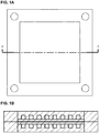
- Examples of cell designs of the present invention include those shown in FIGs. 2A-B , 3A-B , 4A-B , and 5A-B .
- the non-conductive frame (200, 300, 400, and 500) makes up the entirety of the cell outside of the active area (210, 310, 410, and 510). This reduces the cost of stack components by replacing the bipolar plate material outside of the active area with a component that can be manufactured by inexpensive molding methods out of inexpensive plastic or plastic composite materials, as described above.
- additional features can be added to the plastic component at very little additional cost, for example manifolds, through-holes, and ports for minimizing shunt currents.
- Tooling costs may be slightly higher, but these are very quickly amortized over the high volumes for repeat parts in typical flow battery stacks involving tens or hundreds of cells.
- Adjacent flow channels are already connected through the diffusion layer, so the fit between bipolar plate and non-conductive cell frame must only be tight enough to discourage flow.
- the fluid resistance at the interface between bipolar plate and non-conductive cell frame must be less than the down-channel fluid resistance and may be approximately the same order as the fluid resistance to an adjacent flow channel through the diffusion layer.
- FIGs. 3A-B , 4A-B , and 5A-B particularly illustrate the concept of restricting or terminating the channels within the non-conductive element, and are compared with the features of FIGs. 2A-B .
- the reader is directed to elements 220, 320, 420, and 520 of FIG. 2A , FIG. 3A , FIG. 4A , and FIG. 5A-B , respectively.
- FIG. 2A illustrates a device comprising a conductive element 200 framed by a non-conductive element 210.
- the conductive element 200 comprises substantially parallel flow channels (shown as shaded tracks), where the flow channels of the flow field butt up and terminate against, but not within, the non-conductive frame, 220, so as to provide an interdigitated flow field.
- FIG. 3A , FIG. 4A , and FIG. 5A illustrate devices in which the interdigitated flow field is defined by 320, 420, and 520, in which the corresponding terminations or restrictions, respectively, are provided by the non-conductive element.
- FIG. 4A and FIG. 5A the fluid dead end happens outside of the active area. This helps improve the uniformity of fluid distribution.
- elements 420 and 520 respectively, show partial restrictions of the fluid flow rather than the full obstruction depicted in FIG. 2A or FIG. 3A .
- the width of the channels are restricted.
- the degree of width restrictions may be the same or different for each individual channel.
- FIG. 5A-B is shows a single step-wise restriction of the height of the channel within the non-conductive element. Again, it should be appreciated that the number, degree, or both number and degree of height restrictions may be the same or different for each individual channel.
- the degree of restriction may reduce the width or height of the respective channel by an amount in a range of from about 10% to about 90% of either the width or height or both, relative to the width or height of the respective channel. In other embodiments, this degree of restriction may reduce the width or height or both by an amount in a range of from about 20% to about 40%, of from about 40% to 60%, of from about 60% to about 80%, or a combination thereof.
- This gradient concept is advantageous to reducing the overall pressure loss through the cell, while still forcing a nominal amount of fluid out of the planar surface and through the diffusion media. Note that the illustrated terminations or restrictions provided by the non-conductive element are not necessarily to scale.
- the fluid assemblies have been described, for the most part, individually, but it should be appreciated that they may be used preferably stacked on one another, in the constructions of at least two and upwards of about 50, about 100, or about 200 fluid flow assembly devices. Further, such assemblies may be used either to circulate gases or liquids, or a combination thereof, in electrochemical devices which include fuel cells, flow batteries, electrolysis stacks, and combinations thereof.
- electrochemical devices which include fuel cells, flow batteries, electrolysis stacks, and combinations thereof.
- adjacent assemblies which together with electrodes and a separator comprise a single cell, vertically and such that the array of substantially parallel channels of one assembly is positioned oblique, and preferably at 90° to the array of substantially parallel channels of the neighboring assembly.
- the adjacent assemblies may be oriented with channels aligned, in either a vertical or horizontal orientation. In such instances, one assembly may have channel dimensions that are wider than the opposing, adjacent assembly, such that the channels these channels are aligned within the wider channels.
- the fluid flow assembly devices may be incorporated into electrochemical devices, including fuel cells, flow batteries, and electrolysis stacks, which themselves are incorporated into larger systems, for example, including cell stacks, storage tanks and pipings for containing and transporting the electrolytes, control hardware and software (which may include safety systems), and at least one power conditioning unit as part of an energy storage system.
- the storage tanks contain the electroactive materials.
- the control software, hardware, and optional safety systems include all sensors, mitigation equipment and electronic/hardware controls and safeguards to ensure safe, autonomous, and efficient operation of the flow battery or other energy storage system.
- Such storage systems may also include a power conditioning unit at the front end of the energy storage system to convert incoming and outgoing power to a voltage and current that is optimal for the energy storage system or the application.
- a power conditioning unit at the front end of the energy storage system to convert incoming and outgoing power to a voltage and current that is optimal for the energy storage system or the application.
- the power conditioning unit would convert incoming AC electricity into DC electricity at an appropriate voltage and current for the electrochemical stack.
- the stack produces DC electrical power and the power conditioning unit converts to AC electrical power at the appropriate voltage and frequency for grid applications.
- Such energy storage systems of the present invention are well suited to sustained charge or discharge cycles of several hour durations. As such, the systems of the present invention are suited to smooth energy supply/demand profiles and provide a mechanism for stabilizing intermittent power generation assets (e.g. from renewable energy sources).
- various embodiments of the present invention include those electrical energy storage applications where such long charge or discharge durations are valuable.
- non-limiting examples of such applications include those where systems of the present invention are connected to an electrical grid include, so as to allow renewables integration, peak load shifting, grid firming, baseload power generation / consumption, energy arbitrage, transmission and distribution asset deferral, weak grid support, and/or frequency regulation.
- the devices or systems of the present invention can be used to provide stable power for applications that are not connected to a grid, or a micro-grid, for example as power sources for remote camps, forward operating bases, off-grid telecommunications, or remote sensors.
Landscapes
- Chemical & Material Sciences (AREA)
- Chemical Kinetics & Catalysis (AREA)
- General Chemical & Material Sciences (AREA)
- Sustainable Development (AREA)
- Sustainable Energy (AREA)
- Engineering & Computer Science (AREA)
- Life Sciences & Earth Sciences (AREA)
- Electrochemistry (AREA)
- Manufacturing & Machinery (AREA)
- Composite Materials (AREA)
- Cell Electrode Carriers And Collectors (AREA)
- Fuel Cell (AREA)
- Inert Electrodes (AREA)
- Electrolytic Production Of Non-Metals, Compounds, Apparatuses Therefor (AREA)
- Mirrors, Picture Frames, Photograph Stands, And Related Fastening Devices (AREA)
Claims (15)
- Ensemble d'écoulement de fluide comprenant :un élément central conducteur disposé à l'intérieur d'un élément non-conducteur ;l'élément non-conducteur étant caractérisé en ce qu'il encadre la périphérie de l'élément central conducteur et en ce que les éléments définissent ensemble une surface sensiblement plane lorsqu'ils sont engagés les uns dans les autres ;l'élément central conducteur et l'élément non-conducteur présentent chacun des canaux d'écoulement qui, lorsqu'ils sont pris ensemble, forment un motif d'écoulement sur la surface sensiblement plane, le motif d'écoulement comprenant un motif d'écoulement interdigité; etdans lequel les canaux d'écoulement sont rétrécis, se terminent ou sont à la fois rétrécis et se terminent au niveau ou à l'intérieur de l'élément non-conducteur.
- Ensemble d'écoulement de fluide selon la revendication 1, dans lequel au moins certains des canaux d'écoulement sont rétrécis, se terminent, ou sont à la fois rétrécis et se terminent au niveau de l'élément non-conducteur.
- Ensemble d'écoulement des fluides selon la revendication 1 ou 2, dans lequel le motif d'écoulement global est un motif d'écoulement interdigité.
- Ensemble d'écoulement de fluide selon la revendication 1 ou 2, dans lequel le motif d'écoulement comprend un motif d'écoulement en serpentin.
- Ensemble d'écoulement de fluide selon la revendication 1 ou 2, dans lequel l'élément central conducteur comprend une pluralité de canaux d'écoulement sensiblement parallèles, dont au moins une partie de chacun a des parois latérales sensiblement parallèles.
- Ensemble d'écoulement de fluide selon la revendication 1 ou 2, dans lequel l'élément conducteur est sensiblement constitué par une pluralité de canaux d'écoulement sensiblement parallèles, dont au moins une partie de chacun a des parois latérales sensiblement parallèles.
- Ensemble d'écoulement de fluide selon la revendication 1 ou 2, dans lequel le motif d'écoulement comprend :l'élément central conducteur comprenant une pluralité de canaux d'écoulement sensiblement parallèles ;l'élément non-conducteur comprenant au moins un espace collecteur ;chaque espace collecteur étant en communication de fluide avec deux ou plusieurs des canaux d'écoulement sensiblement parallèles de l'élément central conducteur.
- Ensemble d'écoulement de fluide selon la revendication 1 ou 2, dans lequel l'élément non-conducteur comprend une matière plastique moulée.
- Ensemble d'écoulement de fluide selon la revendication 1 ou 2, dans lequel l'élément central conducteur et l'élément non-conducteur sont engagés par une liaison à encliquetage, ou sont maintenus en place par des adhésifs, des soudures au laser ou par ultrasons, ou simplement empilés l'un sur l'autre.
- Ensemble d'écoulement de fluide selon la revendication 1 ou 2, dans lequel l'élément central conducteur est une plaque ayant un évidement qui reçoit un média d'écoulement, l'évidement étant dimensionné de telle sorte que le média d'écoulement est comprimé jusqu'au degré souhaité lorsqu'il est pressé contre le côté plat de la plaque adjacente.
- Ensemble d'écoulement de fluide selon la revendication 10, dans lequel le média d'écoulement comprend du métal, du carbone ou un liant de polymère et est constitué par du tissu, du feutre non tissé, du papier, de la mousse de verre expansée ou réticulée, des feuilles perforées ou un treillis expansé.
- Ensemble d'écoulement de fluide selon la revendication 2, dans lequel au moins certains des canaux d'écoulement sont rétrécis à l'intérieur de l'élément non-conducteur en réduisant la hauteur, la largeur, ou à la fois la hauteur et la largeur des canaux d'écoulement à l'intérieur de l'élément non-conducteur.
- Ensemble d'écoulement de fluide selon la revendication 12, dans lequel la hauteur ou la largeur d'une partie rétrécie des canaux dans l'élément non-conducteur est d'environ 10 % à environ 90 % de la hauteur ou de la largeur des canaux dans l'élément conducteur.
- Ensemble d'écoulement de fluide selon la revendication 2, dans lequel au moins certains des canaux d'écoulement se terminent à l'intérieur de l'élément non-conducteur de telle sorte que les terminaisons se trouvent à distance de l'élément central conducteur.
- Système de stockage d'énergie comprenant l'ensemble d'écoulement de fluide selon l'une quelconque des revendications 1 à 14.
Applications Claiming Priority (3)
| Application Number | Priority Date | Filing Date | Title |
|---|---|---|---|
| US201361881041P | 2013-09-23 | 2013-09-23 | |
| EP14845729.4A EP3050147B1 (fr) | 2013-09-23 | 2014-09-22 | Conception de plaque bipolaire avec cadre non conducteur |
| PCT/US2014/056766 WO2015042520A1 (fr) | 2013-09-23 | 2014-09-22 | Conception de plaque bipolaire à armature d'image non conductrice |
Related Parent Applications (2)
| Application Number | Title | Priority Date | Filing Date |
|---|---|---|---|
| EP14845729.4A Division EP3050147B1 (fr) | 2013-09-23 | 2014-09-22 | Conception de plaque bipolaire avec cadre non conducteur |
| EP14845729.4A Division-Into EP3050147B1 (fr) | 2013-09-23 | 2014-09-22 | Conception de plaque bipolaire avec cadre non conducteur |
Publications (2)
| Publication Number | Publication Date |
|---|---|
| EP3514873A1 EP3514873A1 (fr) | 2019-07-24 |
| EP3514873B1 true EP3514873B1 (fr) | 2021-05-19 |
Family
ID=52689498
Family Applications (2)
| Application Number | Title | Priority Date | Filing Date |
|---|---|---|---|
| EP14845729.4A Active EP3050147B1 (fr) | 2013-09-23 | 2014-09-22 | Conception de plaque bipolaire avec cadre non conducteur |
| EP19158872.2A Active EP3514873B1 (fr) | 2013-09-23 | 2014-09-22 | Conception de plaque bipolaire avec cadre non conducteur |
Family Applications Before (1)
| Application Number | Title | Priority Date | Filing Date |
|---|---|---|---|
| EP14845729.4A Active EP3050147B1 (fr) | 2013-09-23 | 2014-09-22 | Conception de plaque bipolaire avec cadre non conducteur |
Country Status (8)
| Country | Link |
|---|---|
| US (2) | US20160240868A1 (fr) |
| EP (2) | EP3050147B1 (fr) |
| JP (1) | JP6543632B2 (fr) |
| KR (1) | KR20160060681A (fr) |
| CN (1) | CN105814725B (fr) |
| CA (1) | CA2924834C (fr) |
| MX (1) | MX2016003683A (fr) |
| WO (1) | WO2015042520A1 (fr) |
Families Citing this family (21)
| Publication number | Priority date | Publication date | Assignee | Title |
|---|---|---|---|---|
| US10418647B2 (en) | 2015-04-15 | 2019-09-17 | Lockheed Martin Energy, Llc | Mitigation of parasitic reactions within flow batteries |
| WO2017031352A1 (fr) | 2015-08-19 | 2017-02-23 | Lockheed Martin Advanced Energy Storage, Llc | Réduction de matières solides à l'intérieur de batteries à circulation |
| US10147957B2 (en) | 2016-04-07 | 2018-12-04 | Lockheed Martin Energy, Llc | Electrochemical cells having designed flow fields and methods for producing the same |
| US10381674B2 (en) | 2016-04-07 | 2019-08-13 | Lockheed Martin Energy, Llc | High-throughput manufacturing processes for making electrochemical unit cells and electrochemical unit cells produced using the same |
| US10109879B2 (en) | 2016-05-27 | 2018-10-23 | Lockheed Martin Energy, Llc | Flow batteries having an electrode with a density gradient and methods for production and use thereof |
| US10403911B2 (en) | 2016-10-07 | 2019-09-03 | Lockheed Martin Energy, Llc | Flow batteries having an interfacially bonded bipolar plate-electrode assembly and methods for production and use thereof |
| AU2016426077A1 (en) * | 2016-10-12 | 2018-06-28 | Sumitomo Electric Industries, Ltd. | Bipolar plate, cell frame, cell stack, and redox flow cell |
| US10573899B2 (en) | 2016-10-18 | 2020-02-25 | Lockheed Martin Energy, Llc | Flow batteries having an electrode with differing hydrophilicity on opposing faces and methods for production and use thereof |
| AU2016402258A1 (en) * | 2016-12-22 | 2018-07-12 | Sumitomo Electric Industries, Ltd. | Cell frame, cell stack, and redox flow battery |
| US10581104B2 (en) | 2017-03-24 | 2020-03-03 | Lockheed Martin Energy, Llc | Flow batteries having a pressure-balanced electrochemical cell stack and associated methods |
| EP3644425A4 (fr) * | 2017-06-21 | 2020-09-23 | Sumitomo Electric Industries, Ltd. | Batterie rédox |
| CN109860490B (zh) * | 2017-11-30 | 2022-08-12 | 宁德新能源科技有限公司 | 电芯、电池以及电芯的隔离膜的封装方法 |
| CN113131098B (zh) | 2018-02-09 | 2024-05-14 | 宁德新能源科技有限公司 | 电芯以及电池 |
| CN109860665B (zh) * | 2019-01-21 | 2020-08-21 | 西安交通大学 | 一种低泵功液流电池及其工作方法 |
| TWI703759B (zh) * | 2019-09-05 | 2020-09-01 | 行政院原子能委員會核能研究所 | 分散式液流電池儲能模組 |
| US12586806B2 (en) * | 2020-09-29 | 2026-03-24 | Sumitomo Electric Industries, Ltd. | Bipolar plate, cell frame, battery cell, cell stack, and redox flow battery |
| PT116826B (pt) * | 2020-10-14 | 2024-04-12 | Fusion Welcome Fuel Unipessoal Lda | Placa flutuante de guiamento de fluxo para células electroquímicas |
| US20220376284A1 (en) * | 2021-05-20 | 2022-11-24 | Nabors Energy Transition Solutions Llc | Systems, devices, and methods for hydrogen energy production and storage |
| CA3250630A1 (fr) | 2022-05-09 | 2023-11-16 | Lockheed Martin Energy, Llc | Batterie à circulation comprenant un réseau fluidique dynamique |
| AU2023269129A1 (en) * | 2022-05-09 | 2024-10-24 | Lockheed Martin Energy, Llc | Bipolar plate bulk molding compound material choice. |
| CN117144392A (zh) * | 2022-05-24 | 2023-12-01 | 海德氢能源科技(江苏)有限公司 | 双极板及其制造方法和电解堆、电解槽 |
Family Cites Families (22)
| Publication number | Priority date | Publication date | Assignee | Title |
|---|---|---|---|---|
| JPH06290795A (ja) * | 1993-03-31 | 1994-10-18 | Mitsubishi Heavy Ind Ltd | 燃料電池用セパレータ |
| US5879826A (en) * | 1995-07-05 | 1999-03-09 | Humboldt State University Foundation | Proton exchange membrane fuel cell |
| US5641586A (en) * | 1995-12-06 | 1997-06-24 | The Regents Of The University Of California Office Of Technology Transfer | Fuel cell with interdigitated porous flow-field |
| US6685809B1 (en) * | 1999-02-04 | 2004-02-03 | Ut-Battelle, Llc | Methods for forming small-volume electrical contacts and material manipulations with fluidic microchannels |
| US6203936B1 (en) * | 1999-03-03 | 2001-03-20 | Lynntech Inc. | Lightweight metal bipolar plates and methods for making the same |
| DE10216306B4 (de) * | 2002-04-14 | 2008-06-12 | Sgl Carbon Ag | Verfahren zur Herstellung einer Kontaktplatte für eine elektrochemische Zelle sowie deren Verwendungen |
| EP1576684A2 (fr) * | 2002-05-09 | 2005-09-21 | The Board of Trustees of The Leland Stanford Junior University | Pile a combustible perfectionnee |
| US20050136317A1 (en) * | 2003-12-19 | 2005-06-23 | 3M Innovative Properties Company | Molded multi-part flow field structure |
| US7951510B2 (en) * | 2004-11-11 | 2011-05-31 | GM Global Technology Operations LLC | Electroconductive polymer coating on electroconductive elements in a fuel cell |
| US7736788B2 (en) * | 2005-08-12 | 2010-06-15 | Nanyang Technological University | Pattern molding of polymeric flow channels for micro fuel cells |
| KR101022111B1 (ko) * | 2005-12-28 | 2011-03-17 | 유티씨 파워 코포레이션 | 부분적으로 폐쇄된 단부를 갖는 연료전지 유동장 채널 |
| JP2008047313A (ja) * | 2006-08-11 | 2008-02-28 | Nok Corp | 燃料電池 |
| JP2008078104A (ja) * | 2006-08-23 | 2008-04-03 | Sumitomo Metal Ind Ltd | バイポーラプレート用部材、バイポーラプレート積層体、セル構造体および固体高分子形燃料電池 |
| JP5068052B2 (ja) * | 2006-09-29 | 2012-11-07 | 昭和電工株式会社 | 燃料電池用セパレータ、燃料電池用セルおよび燃料電池用セルユニット、ならびに燃料電池用セパレータおよび燃料電池用セルユニットの製造方法 |
| JP5181634B2 (ja) * | 2006-12-04 | 2013-04-10 | トヨタ自動車株式会社 | 燃料電池 |
| WO2010033118A1 (fr) * | 2008-09-18 | 2010-03-25 | Utc Fuel Cells, Llc | Plaque bipolaire pour pile à combustible |
| JP2013518362A (ja) * | 2010-01-25 | 2013-05-20 | ラモット アット テル−アヴィヴ ユニヴァーシテイ リミテッド | バイポーラプレート及び該バイポーラプレートを含む再生型燃料電池積層体 |
| JP2011228059A (ja) * | 2010-04-16 | 2011-11-10 | Sumitomo Electric Ind Ltd | レドックスフロー電池用双極板 |
| JP5751032B2 (ja) * | 2011-06-06 | 2015-07-22 | トヨタ自動車株式会社 | 酵素燃料電池 |
| US10446860B2 (en) * | 2011-06-23 | 2019-10-15 | Audi Ag | Flow field configuration for fuel cell plate |
| EP2557621A1 (fr) * | 2011-08-10 | 2013-02-13 | The European Union, represented by the European Commission | Pile à combustible |
| DE102011120802A1 (de) * | 2011-12-10 | 2013-06-13 | Daimler Ag | Bipolarplatte zumindest aus einem Kunststoff für eine Brennstoffzelle und Verfahren zur Herstellung einer solchen Bipolarplatte |
-
2014
- 2014-09-22 MX MX2016003683A patent/MX2016003683A/es unknown
- 2014-09-22 EP EP14845729.4A patent/EP3050147B1/fr active Active
- 2014-09-22 CN CN201480052418.5A patent/CN105814725B/zh active Active
- 2014-09-22 JP JP2016544047A patent/JP6543632B2/ja active Active
- 2014-09-22 CA CA2924834A patent/CA2924834C/fr active Active
- 2014-09-22 US US15/024,344 patent/US20160240868A1/en not_active Abandoned
- 2014-09-22 EP EP19158872.2A patent/EP3514873B1/fr active Active
- 2014-09-22 WO PCT/US2014/056766 patent/WO2015042520A1/fr not_active Ceased
- 2014-09-22 KR KR1020167010206A patent/KR20160060681A/ko not_active Withdrawn
-
2022
- 2022-09-06 US US17/929,863 patent/US20230076847A1/en active Pending
Non-Patent Citations (1)
| Title |
|---|
| None * |
Also Published As
| Publication number | Publication date |
|---|---|
| CN105814725A (zh) | 2016-07-27 |
| JP6543632B2 (ja) | 2019-07-10 |
| EP3514873A1 (fr) | 2019-07-24 |
| US20160240868A1 (en) | 2016-08-18 |
| CA2924834A1 (fr) | 2015-03-26 |
| US20230076847A1 (en) | 2023-03-09 |
| MX2016003683A (es) | 2016-08-11 |
| CA2924834C (fr) | 2021-06-29 |
| JP2016536769A (ja) | 2016-11-24 |
| WO2015042520A1 (fr) | 2015-03-26 |
| CN105814725B (zh) | 2019-09-06 |
| EP3050147A1 (fr) | 2016-08-03 |
| EP3050147A4 (fr) | 2017-06-07 |
| KR20160060681A (ko) | 2016-05-30 |
| EP3050147B1 (fr) | 2019-05-01 |
Similar Documents
| Publication | Publication Date | Title |
|---|---|---|
| US20230076847A1 (en) | Bipolar plate design with non-conductive picture frame | |
| US11824243B2 (en) | Electrode assembly and flow battery with improved electrolyte distribution | |
| CN103339762B (zh) | 液流电池单元堆 | |
| EP3167505B1 (fr) | Ensembles de piles à combustible présentant un flux amélioré du réactif | |
| US10381667B2 (en) | High performance redox flow battery stack | |
| US20140329168A1 (en) | Hybrid bipolar plate assembly for fuel cells | |
| AU2015344623B2 (en) | Battery cell and redox flow battery | |
| KR20140084011A (ko) | 레독스 흐름 배터리 반응기 셀을 조립하는 시스템 및 방법 | |
| WO2015070066A1 (fr) | Configurations de cellule et de bloc de cellules pour systèmes de batteries à flux d'oxydoréduction | |
| DE102013225159A1 (de) | Anordnung elektrochemischer Zellen | |
| EP2926400B1 (fr) | Ensemble embase-électrode-membrane destiné à une pile électrochimique d'oxydoréduction pour le stockage d'énergie de flux | |
| WO2020129022A2 (fr) | Batterie à flux redox comprenant un empilement de cadres d'écoulement et cadre à flux redox associé | |
| KR101353961B1 (ko) | 전기화학적 플로우 셀 스택 구조 및 이를 포함하는 레독스 플로우 전지 | |
| AU2016342919B2 (en) | Redox flow battery electrode, and redox flow battery | |
| AU2017261462B2 (en) | Bipolar plate, cell frame, cell stack, and redox flow battery | |
| US10780399B2 (en) | Membrane stack and method for making the same | |
| US11764384B2 (en) | Segmented frames for redox flow batteries | |
| KR20180053401A (ko) | 힘 집중기 패턴을 갖는 바이폴라 플레이트 | |
| US20190109334A1 (en) | Cell plates for redox flow batteries | |
| US20210066730A1 (en) | Thermal Managing End Plate For Fuel Cell Stack Assembly | |
| US20160104901A1 (en) | Method for making complex bipolar plates for fuel cells using extrusion |
Legal Events
| Date | Code | Title | Description |
|---|---|---|---|
| PUAI | Public reference made under article 153(3) epc to a published international application that has entered the european phase |
Free format text: ORIGINAL CODE: 0009012 |
|
| STAA | Information on the status of an ep patent application or granted ep patent |
Free format text: STATUS: THE APPLICATION HAS BEEN PUBLISHED |
|
| AC | Divisional application: reference to earlier application |
Ref document number: 3050147 Country of ref document: EP Kind code of ref document: P |
|
| AK | Designated contracting states |
Kind code of ref document: A1 Designated state(s): AL AT BE BG CH CY CZ DE DK EE ES FI FR GB GR HR HU IE IS IT LI LT LU LV MC MK MT NL NO PL PT RO RS SE SI SK SM TR |
|
| STAA | Information on the status of an ep patent application or granted ep patent |
Free format text: STATUS: REQUEST FOR EXAMINATION WAS MADE |
|
| 17P | Request for examination filed |
Effective date: 20191218 |
|
| RBV | Designated contracting states (corrected) |
Designated state(s): AL AT BE BG CH CY CZ DE DK EE ES FI FR GB GR HR HU IE IS IT LI LT LU LV MC MK MT NL NO PL PT RO RS SE SI SK SM TR |
|
| RIC1 | Information provided on ipc code assigned before grant |
Ipc: H01M 8/0258 20160101AFI20200930BHEP Ipc: H01M 8/0223 20160101ALI20200930BHEP |
|
| GRAP | Despatch of communication of intention to grant a patent |
Free format text: ORIGINAL CODE: EPIDOSNIGR1 |
|
| STAA | Information on the status of an ep patent application or granted ep patent |
Free format text: STATUS: GRANT OF PATENT IS INTENDED |
|
| INTG | Intention to grant announced |
Effective date: 20201203 |
|
| GRAS | Grant fee paid |
Free format text: ORIGINAL CODE: EPIDOSNIGR3 |
|
| GRAA | (expected) grant |
Free format text: ORIGINAL CODE: 0009210 |
|
| STAA | Information on the status of an ep patent application or granted ep patent |
Free format text: STATUS: THE PATENT HAS BEEN GRANTED |
|
| AC | Divisional application: reference to earlier application |
Ref document number: 3050147 Country of ref document: EP Kind code of ref document: P |
|
| AK | Designated contracting states |
Kind code of ref document: B1 Designated state(s): AL AT BE BG CH CY CZ DE DK EE ES FI FR GB GR HR HU IE IS IT LI LT LU LV MC MK MT NL NO PL PT RO RS SE SI SK SM TR |
|
| REG | Reference to a national code |
Ref country code: GB Ref legal event code: FG4D |
|
| REG | Reference to a national code |
Ref country code: CH Ref legal event code: EP |
|
| REG | Reference to a national code |
Ref country code: DE Ref legal event code: R096 Ref document number: 602014077646 Country of ref document: DE |
|
| REG | Reference to a national code |
Ref country code: AT Ref legal event code: REF Ref document number: 1394863 Country of ref document: AT Kind code of ref document: T Effective date: 20210615 |
|
| REG | Reference to a national code |
Ref country code: IE Ref legal event code: FG4D |
|
| REG | Reference to a national code |
Ref country code: FI Ref legal event code: FGE |
|
| REG | Reference to a national code |
Ref country code: LT Ref legal event code: MG9D |
|
| REG | Reference to a national code |
Ref country code: AT Ref legal event code: MK05 Ref document number: 1394863 Country of ref document: AT Kind code of ref document: T Effective date: 20210519 |
|
| REG | Reference to a national code |
Ref country code: NL Ref legal event code: MP Effective date: 20210519 |
|
| PG25 | Lapsed in a contracting state [announced via postgrant information from national office to epo] |
Ref country code: BG Free format text: LAPSE BECAUSE OF FAILURE TO SUBMIT A TRANSLATION OF THE DESCRIPTION OR TO PAY THE FEE WITHIN THE PRESCRIBED TIME-LIMIT Effective date: 20210819 Ref country code: AT Free format text: LAPSE BECAUSE OF FAILURE TO SUBMIT A TRANSLATION OF THE DESCRIPTION OR TO PAY THE FEE WITHIN THE PRESCRIBED TIME-LIMIT Effective date: 20210519 Ref country code: HR Free format text: LAPSE BECAUSE OF FAILURE TO SUBMIT A TRANSLATION OF THE DESCRIPTION OR TO PAY THE FEE WITHIN THE PRESCRIBED TIME-LIMIT Effective date: 20210519 Ref country code: LT Free format text: LAPSE BECAUSE OF FAILURE TO SUBMIT A TRANSLATION OF THE DESCRIPTION OR TO PAY THE FEE WITHIN THE PRESCRIBED TIME-LIMIT Effective date: 20210519 |
|
| PG25 | Lapsed in a contracting state [announced via postgrant information from national office to epo] |
Ref country code: PL Free format text: LAPSE BECAUSE OF FAILURE TO SUBMIT A TRANSLATION OF THE DESCRIPTION OR TO PAY THE FEE WITHIN THE PRESCRIBED TIME-LIMIT Effective date: 20210519 Ref country code: NO Free format text: LAPSE BECAUSE OF FAILURE TO SUBMIT A TRANSLATION OF THE DESCRIPTION OR TO PAY THE FEE WITHIN THE PRESCRIBED TIME-LIMIT Effective date: 20210819 Ref country code: LV Free format text: LAPSE BECAUSE OF FAILURE TO SUBMIT A TRANSLATION OF THE DESCRIPTION OR TO PAY THE FEE WITHIN THE PRESCRIBED TIME-LIMIT Effective date: 20210519 Ref country code: SE Free format text: LAPSE BECAUSE OF FAILURE TO SUBMIT A TRANSLATION OF THE DESCRIPTION OR TO PAY THE FEE WITHIN THE PRESCRIBED TIME-LIMIT Effective date: 20210519 Ref country code: PT Free format text: LAPSE BECAUSE OF FAILURE TO SUBMIT A TRANSLATION OF THE DESCRIPTION OR TO PAY THE FEE WITHIN THE PRESCRIBED TIME-LIMIT Effective date: 20210920 Ref country code: RS Free format text: LAPSE BECAUSE OF FAILURE TO SUBMIT A TRANSLATION OF THE DESCRIPTION OR TO PAY THE FEE WITHIN THE PRESCRIBED TIME-LIMIT Effective date: 20210519 Ref country code: GR Free format text: LAPSE BECAUSE OF FAILURE TO SUBMIT A TRANSLATION OF THE DESCRIPTION OR TO PAY THE FEE WITHIN THE PRESCRIBED TIME-LIMIT Effective date: 20210820 Ref country code: IS Free format text: LAPSE BECAUSE OF FAILURE TO SUBMIT A TRANSLATION OF THE DESCRIPTION OR TO PAY THE FEE WITHIN THE PRESCRIBED TIME-LIMIT Effective date: 20210919 |
|
| PG25 | Lapsed in a contracting state [announced via postgrant information from national office to epo] |
Ref country code: NL Free format text: LAPSE BECAUSE OF FAILURE TO SUBMIT A TRANSLATION OF THE DESCRIPTION OR TO PAY THE FEE WITHIN THE PRESCRIBED TIME-LIMIT Effective date: 20210519 |
|
| PG25 | Lapsed in a contracting state [announced via postgrant information from national office to epo] |
Ref country code: SK Free format text: LAPSE BECAUSE OF FAILURE TO SUBMIT A TRANSLATION OF THE DESCRIPTION OR TO PAY THE FEE WITHIN THE PRESCRIBED TIME-LIMIT Effective date: 20210519 Ref country code: EE Free format text: LAPSE BECAUSE OF FAILURE TO SUBMIT A TRANSLATION OF THE DESCRIPTION OR TO PAY THE FEE WITHIN THE PRESCRIBED TIME-LIMIT Effective date: 20210519 Ref country code: ES Free format text: LAPSE BECAUSE OF FAILURE TO SUBMIT A TRANSLATION OF THE DESCRIPTION OR TO PAY THE FEE WITHIN THE PRESCRIBED TIME-LIMIT Effective date: 20210519 Ref country code: SM Free format text: LAPSE BECAUSE OF FAILURE TO SUBMIT A TRANSLATION OF THE DESCRIPTION OR TO PAY THE FEE WITHIN THE PRESCRIBED TIME-LIMIT Effective date: 20210519 Ref country code: RO Free format text: LAPSE BECAUSE OF FAILURE TO SUBMIT A TRANSLATION OF THE DESCRIPTION OR TO PAY THE FEE WITHIN THE PRESCRIBED TIME-LIMIT Effective date: 20210519 Ref country code: DK Free format text: LAPSE BECAUSE OF FAILURE TO SUBMIT A TRANSLATION OF THE DESCRIPTION OR TO PAY THE FEE WITHIN THE PRESCRIBED TIME-LIMIT Effective date: 20210519 Ref country code: CZ Free format text: LAPSE BECAUSE OF FAILURE TO SUBMIT A TRANSLATION OF THE DESCRIPTION OR TO PAY THE FEE WITHIN THE PRESCRIBED TIME-LIMIT Effective date: 20210519 |
|
| REG | Reference to a national code |
Ref country code: DE Ref legal event code: R097 Ref document number: 602014077646 Country of ref document: DE |
|
| PLBE | No opposition filed within time limit |
Free format text: ORIGINAL CODE: 0009261 |
|
| STAA | Information on the status of an ep patent application or granted ep patent |
Free format text: STATUS: NO OPPOSITION FILED WITHIN TIME LIMIT |
|
| 26N | No opposition filed |
Effective date: 20220222 |
|
| REG | Reference to a national code |
Ref country code: CH Ref legal event code: PL |
|
| REG | Reference to a national code |
Ref country code: BE Ref legal event code: MM Effective date: 20210930 |
|
| PG25 | Lapsed in a contracting state [announced via postgrant information from national office to epo] |
Ref country code: IS Free format text: LAPSE BECAUSE OF FAILURE TO SUBMIT A TRANSLATION OF THE DESCRIPTION OR TO PAY THE FEE WITHIN THE PRESCRIBED TIME-LIMIT Effective date: 20210919 Ref country code: MC Free format text: LAPSE BECAUSE OF FAILURE TO SUBMIT A TRANSLATION OF THE DESCRIPTION OR TO PAY THE FEE WITHIN THE PRESCRIBED TIME-LIMIT Effective date: 20210519 Ref country code: AL Free format text: LAPSE BECAUSE OF FAILURE TO SUBMIT A TRANSLATION OF THE DESCRIPTION OR TO PAY THE FEE WITHIN THE PRESCRIBED TIME-LIMIT Effective date: 20210519 |
|
| PG25 | Lapsed in a contracting state [announced via postgrant information from national office to epo] |
Ref country code: LU Free format text: LAPSE BECAUSE OF NON-PAYMENT OF DUE FEES Effective date: 20210922 Ref country code: IT Free format text: LAPSE BECAUSE OF FAILURE TO SUBMIT A TRANSLATION OF THE DESCRIPTION OR TO PAY THE FEE WITHIN THE PRESCRIBED TIME-LIMIT Effective date: 20210519 Ref country code: IE Free format text: LAPSE BECAUSE OF NON-PAYMENT OF DUE FEES Effective date: 20210922 Ref country code: BE Free format text: LAPSE BECAUSE OF NON-PAYMENT OF DUE FEES Effective date: 20210930 |
|
| PG25 | Lapsed in a contracting state [announced via postgrant information from national office to epo] |
Ref country code: LI Free format text: LAPSE BECAUSE OF NON-PAYMENT OF DUE FEES Effective date: 20210930 Ref country code: CH Free format text: LAPSE BECAUSE OF NON-PAYMENT OF DUE FEES Effective date: 20210930 |
|
| P01 | Opt-out of the competence of the unified patent court (upc) registered |
Effective date: 20230523 |
|
| PG25 | Lapsed in a contracting state [announced via postgrant information from national office to epo] |
Ref country code: CY Free format text: LAPSE BECAUSE OF FAILURE TO SUBMIT A TRANSLATION OF THE DESCRIPTION OR TO PAY THE FEE WITHIN THE PRESCRIBED TIME-LIMIT Effective date: 20210519 |
|
| PG25 | Lapsed in a contracting state [announced via postgrant information from national office to epo] |
Ref country code: HU Free format text: LAPSE BECAUSE OF FAILURE TO SUBMIT A TRANSLATION OF THE DESCRIPTION OR TO PAY THE FEE WITHIN THE PRESCRIBED TIME-LIMIT; INVALID AB INITIO Effective date: 20140922 |
|
| PG25 | Lapsed in a contracting state [announced via postgrant information from national office to epo] |
Ref country code: MK Free format text: LAPSE BECAUSE OF FAILURE TO SUBMIT A TRANSLATION OF THE DESCRIPTION OR TO PAY THE FEE WITHIN THE PRESCRIBED TIME-LIMIT Effective date: 20210519 |
|
| PG25 | Lapsed in a contracting state [announced via postgrant information from national office to epo] |
Ref country code: MT Free format text: LAPSE BECAUSE OF FAILURE TO SUBMIT A TRANSLATION OF THE DESCRIPTION OR TO PAY THE FEE WITHIN THE PRESCRIBED TIME-LIMIT Effective date: 20210519 |
|
| PGFP | Annual fee paid to national office [announced via postgrant information from national office to epo] |
Ref country code: FI Payment date: 20250925 Year of fee payment: 12 |
|
| PGFP | Annual fee paid to national office [announced via postgrant information from national office to epo] |
Ref country code: DE Payment date: 20250929 Year of fee payment: 12 |
|
| PGFP | Annual fee paid to national office [announced via postgrant information from national office to epo] |
Ref country code: GB Payment date: 20250929 Year of fee payment: 12 |
|
| PGFP | Annual fee paid to national office [announced via postgrant information from national office to epo] |
Ref country code: FR Payment date: 20250925 Year of fee payment: 12 |
|
| PG25 | Lapsed in a contracting state [announced via postgrant information from national office to epo] |
Ref country code: TR Free format text: LAPSE BECAUSE OF FAILURE TO SUBMIT A TRANSLATION OF THE DESCRIPTION OR TO PAY THE FEE WITHIN THE PRESCRIBED TIME-LIMIT Effective date: 20210519 |