EP3514892A1 - Connecteur enfichable - Google Patents
Connecteur enfichable Download PDFInfo
- Publication number
- EP3514892A1 EP3514892A1 EP18208607.4A EP18208607A EP3514892A1 EP 3514892 A1 EP3514892 A1 EP 3514892A1 EP 18208607 A EP18208607 A EP 18208607A EP 3514892 A1 EP3514892 A1 EP 3514892A1
- Authority
- EP
- European Patent Office
- Prior art keywords
- electrical
- contacts
- einsteckfortsatzaufnahme
- mating contacts
- plug connection
- Prior art date
- Legal status (The legal status is an assumption and is not a legal conclusion. Google has not performed a legal analysis and makes no representation as to the accuracy of the status listed.)
- Granted
Links
Images


Classifications
-
- H—ELECTRICITY
- H01—ELECTRIC ELEMENTS
- H01R—ELECTRICALLY-CONDUCTIVE CONNECTIONS; STRUCTURAL ASSOCIATIONS OF A PLURALITY OF MUTUALLY-INSULATED ELECTRICAL CONNECTING ELEMENTS; COUPLING DEVICES; CURRENT COLLECTORS
- H01R13/00—Details of coupling devices of the kinds covered by groups H01R12/70 or H01R24/00 - H01R33/00
- H01R13/64—Means for preventing incorrect coupling
- H01R13/642—Means for preventing incorrect coupling by position or shape of contact members
-
- G—PHYSICS
- G02—OPTICS
- G02B—OPTICAL ELEMENTS, SYSTEMS OR APPARATUS
- G02B6/00—Light guides; Structural details of arrangements comprising light guides and other optical elements, e.g. couplings
- G02B6/24—Coupling light guides
- G02B6/36—Mechanical coupling means
- G02B6/38—Mechanical coupling means having fibre to fibre mating means
- G02B6/3807—Dismountable connectors, i.e. comprising plugs
- G02B6/381—Dismountable connectors, i.e. comprising plugs of the ferrule type, e.g. fibre ends embedded in ferrules, connecting a pair of fibres
- G02B6/3825—Dismountable connectors, i.e. comprising plugs of the ferrule type, e.g. fibre ends embedded in ferrules, connecting a pair of fibres with an intermediate part, e.g. adapter, receptacle, linking two plugs
-
- H—ELECTRICITY
- H01—ELECTRIC ELEMENTS
- H01R—ELECTRICALLY-CONDUCTIVE CONNECTIONS; STRUCTURAL ASSOCIATIONS OF A PLURALITY OF MUTUALLY-INSULATED ELECTRICAL CONNECTING ELEMENTS; COUPLING DEVICES; CURRENT COLLECTORS
- H01R13/00—Details of coupling devices of the kinds covered by groups H01R12/70 or H01R24/00 - H01R33/00
- H01R13/64—Means for preventing incorrect coupling
-
- G—PHYSICS
- G02—OPTICS
- G02B—OPTICAL ELEMENTS, SYSTEMS OR APPARATUS
- G02B6/00—Light guides; Structural details of arrangements comprising light guides and other optical elements, e.g. couplings
- G02B6/24—Coupling light guides
- G02B6/36—Mechanical coupling means
- G02B6/38—Mechanical coupling means having fibre to fibre mating means
- G02B6/3807—Dismountable connectors, i.e. comprising plugs
- G02B6/3833—Details of mounting fibres in ferrules; Assembly methods; Manufacture
- G02B6/3847—Details of mounting fibres in ferrules; Assembly methods; Manufacture with means preventing fibre end damage, e.g. recessed fibre surfaces
- G02B6/3849—Details of mounting fibres in ferrules; Assembly methods; Manufacture with means preventing fibre end damage, e.g. recessed fibre surfaces using mechanical protective elements, e.g. caps, hoods, sealing membranes
-
- G—PHYSICS
- G02—OPTICS
- G02B—OPTICAL ELEMENTS, SYSTEMS OR APPARATUS
- G02B6/00—Light guides; Structural details of arrangements comprising light guides and other optical elements, e.g. couplings
- G02B6/24—Coupling light guides
- G02B6/36—Mechanical coupling means
- G02B6/38—Mechanical coupling means having fibre to fibre mating means
- G02B6/3807—Dismountable connectors, i.e. comprising plugs
- G02B6/3833—Details of mounting fibres in ferrules; Assembly methods; Manufacture
- G02B6/3865—Details of mounting fibres in ferrules; Assembly methods; Manufacture fabricated by using moulding techniques
-
- G—PHYSICS
- G02—OPTICS
- G02B—OPTICAL ELEMENTS, SYSTEMS OR APPARATUS
- G02B6/00—Light guides; Structural details of arrangements comprising light guides and other optical elements, e.g. couplings
- G02B6/24—Coupling light guides
- G02B6/36—Mechanical coupling means
- G02B6/38—Mechanical coupling means having fibre to fibre mating means
- G02B6/3807—Dismountable connectors, i.e. comprising plugs
- G02B6/3869—Mounting ferrules to connector body, i.e. plugs
-
- G—PHYSICS
- G02—OPTICS
- G02B—OPTICAL ELEMENTS, SYSTEMS OR APPARATUS
- G02B6/00—Light guides; Structural details of arrangements comprising light guides and other optical elements, e.g. couplings
- G02B6/24—Coupling light guides
- G02B6/36—Mechanical coupling means
- G02B6/38—Mechanical coupling means having fibre to fibre mating means
- G02B6/3807—Dismountable connectors, i.e. comprising plugs
- G02B6/3873—Connectors using guide surfaces for aligning ferrule ends, e.g. tubes, sleeves, V-grooves, rods, pins, balls
- G02B6/3874—Connectors using guide surfaces for aligning ferrule ends, e.g. tubes, sleeves, V-grooves, rods, pins, balls using tubes, sleeves to align ferrules
- G02B6/3878—Connectors using guide surfaces for aligning ferrule ends, e.g. tubes, sleeves, V-grooves, rods, pins, balls using tubes, sleeves to align ferrules comprising a plurality of ferrules, branching and break-out means
- G02B6/3879—Linking of individual connector plugs to an overconnector, e.g. using clamps, clips, common housings comprising several individual connector plugs
-
- H—ELECTRICITY
- H01—ELECTRIC ELEMENTS
- H01R—ELECTRICALLY-CONDUCTIVE CONNECTIONS; STRUCTURAL ASSOCIATIONS OF A PLURALITY OF MUTUALLY-INSULATED ELECTRICAL CONNECTING ELEMENTS; COUPLING DEVICES; CURRENT COLLECTORS
- H01R13/00—Details of coupling devices of the kinds covered by groups H01R12/70 or H01R24/00 - H01R33/00
- H01R13/46—Bases; Cases
- H01R13/502—Bases; Cases composed of different pieces
-
- H—ELECTRICITY
- H01—ELECTRIC ELEMENTS
- H01R—ELECTRICALLY-CONDUCTIVE CONNECTIONS; STRUCTURAL ASSOCIATIONS OF A PLURALITY OF MUTUALLY-INSULATED ELECTRICAL CONNECTING ELEMENTS; COUPLING DEVICES; CURRENT COLLECTORS
- H01R13/00—Details of coupling devices of the kinds covered by groups H01R12/70 or H01R24/00 - H01R33/00
- H01R13/64—Means for preventing incorrect coupling
- H01R13/645—Means for preventing incorrect coupling by exchangeable elements on case or base
-
- G—PHYSICS
- G02—OPTICS
- G02B—OPTICAL ELEMENTS, SYSTEMS OR APPARATUS
- G02B6/00—Light guides; Structural details of arrangements comprising light guides and other optical elements, e.g. couplings
- G02B6/24—Coupling light guides
- G02B6/42—Coupling light guides with opto-electronic elements
- G02B6/4296—Coupling light guides with opto-electronic elements coupling with sources of high radiant energy, e.g. high power lasers, high temperature light sources
- G02B2006/4297—Coupling light guides with opto-electronic elements coupling with sources of high radiant energy, e.g. high power lasers, high temperature light sources having protection means, e.g. protecting humans against accidental exposure to harmful laser radiation
-
- H—ELECTRICITY
- H01—ELECTRIC ELEMENTS
- H01R—ELECTRICALLY-CONDUCTIVE CONNECTIONS; STRUCTURAL ASSOCIATIONS OF A PLURALITY OF MUTUALLY-INSULATED ELECTRICAL CONNECTING ELEMENTS; COUPLING DEVICES; CURRENT COLLECTORS
- H01R13/00—Details of coupling devices of the kinds covered by groups H01R12/70 or H01R24/00 - H01R33/00
- H01R13/62—Means for facilitating engagement or disengagement of coupling parts or for holding them in engagement
- H01R13/625—Casing or ring with bayonet engagement
-
- H—ELECTRICITY
- H01—ELECTRIC ELEMENTS
- H01R—ELECTRICALLY-CONDUCTIVE CONNECTIONS; STRUCTURAL ASSOCIATIONS OF A PLURALITY OF MUTUALLY-INSULATED ELECTRICAL CONNECTING ELEMENTS; COUPLING DEVICES; CURRENT COLLECTORS
- H01R13/00—Details of coupling devices of the kinds covered by groups H01R12/70 or H01R24/00 - H01R33/00
- H01R13/66—Structural association with built-in electrical component
- H01R13/70—Structural association with built-in electrical component with built-in switch
- H01R13/71—Contact members of coupling parts operating as switch, e.g. linear or rotational movement required after mechanical engagement of coupling part to establish electrical connection
Definitions
- the present invention relates to a plug connection for the transmission of electrical current with a male connector and a female connector, wherein the male connector has a Einsteckfortsatz with a Einsteckfortsatzmantelwand and electrical contacts, wherein in an enclosed by the Einsteckfortsatzmantelwand Einsteckfortsatzinnenraum the electrical contacts are arranged, and the female connector has a Einsteckfortsatzability with a Einsteckfortsatzareamantelwand and electrical mating contacts, wherein in a Einsteckfortsatzemantelwand surrounded Einsteckfortsatzareainnenraum the electrical mating contacts are arranged, wherein on a shell wall, which is the Einsteckfortsatzmantelwand or Einsteckfortsatzabilitymantelwand, at least one projection and the other of these shell walls at least a receiving slot corresponding to the projection, w obei in an undamaged state of the projection and the receiving slot of the insertion extension is exclusively inserted starting from a unique, predetermined by the
- Such electrical power transmission connectors are known in the art and are shown, for example, in Community Designs 001229827, especially 001229827-0001 and -0006, 002677641, especially 002677641-0001, and 001393623-0001 and -0002. Due to the projections and the respective corresponding receiving slots is prevented in proper operation in the prior art that mating connectors are not plugged into each other. Furthermore, it is ensured that associated plug-in connectors when used properly only in the specified or provided insertion position can be inserted into each other.
- the object of the invention is to provide an additional measure that can be prevented with connectors of the type mentioned above, that it by plugging together mismatched connectors and / or by mating connectors in a position not provided for this purpose by mistake for incorrect electrical contact the electrical contacts with the electrical mating contacts comes.
- the invention proposes a connector according to claim 1.
- the male connector in Einsteckfortsatzinnenraum additionally at least one molding and the female connector Einsteckfortsatzareainnenraum additionally comprise at least one counter-part, wherein the molded part and the counter-molded part together a locking device for preventing electrical contacting of the electrical contacts with the electrical Form mating contacts when inserting the Einsteckfortsatzes in the Einsteckfortsatza starting from a deviating from the unique predetermined insertion position.
- the projections and / or receiving slots on the insertion extension facing outward are exposed to increased wear and thus may be damaged or even completely removed.
- the arrangement of the molded part in the Einsteckfortsatzinnenraum and the counter-molded part in Einsteckfortsatzareainnenraum has the advantage that the molding and the counter-molding of the corresponding Einsteckfortsatzmantelwand or the corresponding Einsteckfortsatzareamantelwand against external influences and especially against abrasion or other impairments is particularly well protected or, which further contributes to the reliable prevention of electrical contacting of the electrical contacts with the respective wrong electrical mating contacts.
- the electrical contacting could also be referred to as electrically conductive interconnection of the electrical contacts to the electrical mating contacts.
- plug connections according to the invention electrical power is generally transmitted. It can be both an electrical signal transmission, in which rather low electrical power is transmitted, as well as an electrical transmission of power with correspondingly high currents and / or voltages. Plug connections according to the invention can therefore be used both for electrical data transmission and for electrical power transmission, e.g. be designed for power supply of electrical equipment. One could also speak of plug-in connections for the transmission of electrical energy and / or electrical signals. Also mixed forms of it are possible. In addition, plug connections according to the invention also need not necessarily be limited to transmitting only electrical currents and / or voltages. In plug connections according to the invention, in addition, e.g. also an optical data transmission or the like may be integrated.
- Both the male connector and the female connector of the connector according to the invention may be cable connector, so to connectors that are connected directly to the cable, but also so-called chassis connector, so connectors are attached to device housings, act.
- the female connector could also be referred to as a socket.
- the projections could also be called elevations, the receiving slots could also be referred to as depressions or recesses or grooves.
- the projections may be arranged both on the Einsteckfortsatzmantelwand and on the Einsteckfortsatzabilitymantelwand and project beyond this. They can face inwards, ie to the respective interior but also to the outside. Accordingly, the receiving slots can be attached to both the Einsteckfortsatzmantelwand and on the Einsteckfortsatzabilitymantelwand or introduced into the respective jacket wall. Mixed forms are also conceivable. It may be per jacket wall to one, but also several projections and / or receiving slots. In the following, in the singular of the projection and the receiving slot is usually spoken. But this is just a linguistic simplification.
- the projections and the receiving slots corresponding thereto serve the male connector in the undamaged state of the projections and receiving slots can only be inserted from the unique, predetermined by the projection and the receiving slot insertion position in the insertion in the insertion insertion receptacle.
- the projections and receiving slots in the undamaged state and with proper handling so actually ensure that it does not come at a wrong plugging the male connector into the female connector.
- the practice has, as already described above, shown that it may come through damage, wear or other impairment of projections and receiving slots but also through improper handling to the insertion of the male connector starting from a wrong, from the unique predetermined insertion position deviating position can be inserted into the Einsteckfortsatzlessness of the female connector.
- the molded part according to the invention in cooperation with the corresponding counterpart part, prevents at least that the male connector can be pushed into the female connector so far that the electrical contacts and the electrical mating contacts are incorrectly connected to one another.
- the unique, from the projection and the receiving slot predetermined insertion position is referred to here for a short time as a unique predetermined insertion position or only as a predetermined insertion position.
- the receiving slot corresponding to a respective projection corresponds in its shape and position so the shape and position or position of the corresponding projection, that in the undamaged state of projection and receiving slot and when used properly plugging just starting from the unique predetermined insertion position is possible ,
- the term of the electrical mating contacts is used only to clarify that this is the electrical contact elements of the female connector. Neither the term of the electrical contacts of the male connector nor the electrical mating contacts of the female connector says anything about the number and physical configuration of the respective electrical contact elements. This can be designed very different and corresponding to each other. Both the number of electrical contacts of the male connector and the number of electrical mating contacts of the female connector may vary. It may be one, two, three or more electrical contacts and correspondingly one, two, three or more electrical mating contacts. Particularly preferred are three electrical contacts and correspondingly three electrical mating contacts. In general, the number of electrical contacts of the male connector corresponds to the number of electrical mating contacts of the female connector in inventive connectors.
- Preferred embodiments of the invention provide that the molded part have at least one stop surface and the counterpart part at least one counter stop surface, wherein the formation of the locking device, the stop surface and the counter stop surface when inserting the insertion in the insertion direction in the Einsteckfortsatz technique starting from one of the unique predetermined insertion position Deviating position abut each other and to prevent the electrical contacting of the electrical contacts with the electrical mating contacts a complete insertion of the insertion in the insertion in the Einsteckfortsatz technique.
- molding and counter-molding as well as stop surface and counter stop surface is, as in the electrical contacts and the electrical mating contacts also ultimately a convention that only serves to simplify the linguistic assignment to the male or female connector and to unify. Therefore, these terms do not say anything about the specific design and arrangement in each connector.
- the molded part is arranged centrally in the insertion projection interior, preferably on a longitudinal central axis of the insertion extension.
- the molding is located between the electrical contacts in Einsteckfortsatzinnenraum.
- the counter-molding is so conveniently located centrally in Einsteckfortsatzinnenraum, preferably on a longitudinal central axis of the Einsteckfortsatz technique.
- the counterpart part is also located between the electrical mating contacts.
- Both the molding and the corresponding counter-molding can be formed very differently in order to represent the locking device according to the invention and their function.
- Preferred variants provide that a part which is the molded part or the counterpart part has at least one free space in which the other of these parts, when inserting the insertion extension in the insertion direction, penetrates into the insertion extension receptacle starting from the predetermined insertion position.
- the free space can thus be formed both on the molding and on the counter-molding.
- the other part, then then just according to the counter-molding or the molding can then penetrate correspondingly in inserting the Einsteckfortsatzes from the unique predetermined insertion position in this space.
- the free space may be V-shaped. It can also be several, for example, two opposing spaces.
- the part penetrating into the free space or the free spaces that is to say correspondingly the shaped part or the counterpart part, is rotatably mounted in the free space, particularly preferably mounted rotatably between two rotation stops.
- the insertion extension in plug-in connections according to the invention that, starting from the unique predetermined insertion position, the insertion extension must be inserted exclusively linearly in the insertion direction into the insertion extension receptacle so as to reach the end position in which the electrical contacts are electrically contacted with the electrical mating contacts.
- Preferred embodiments of the invention provide that the insertion extension, starting from the predetermined insertion position in the insertion in the insertion extension receptacle to achieve a fully inserted position can be inserted and is rotatable starting from the fully inserted position around the plug-in direction in an end position, wherein in the End position the electrical contacts are electrically contacted with the electrical mating contacts.
- the insertion direction coincides favorably with the longitudinal center axes of the insertion extension and the Einsteckfortsatz technique together or is formed coaxially with these.
- said end position in which the electrical contacts are electrically contacted with the electrical mating contacts, is only reached when starting from the unique predetermined insertion position initially takes place a linear insertion in the insertion direction.
- the fully inserted position is reached, from which the insertion extension, preferably the entire male connector, is then rotated around the insertion direction into the end position.
- the jacket wall in which the receiving slot is arranged, at least one extending in a circumferential direction and adjoining the receiving slot receiving channel is arranged, in which the projection when turning from the fully inserted position into the end position is.
- the, preferably all, electrical contacts are arranged on a common circular path of the electrical contacts and / or that, preferably all, electrical mating contacts are arranged on a common circular path of the electrical mating contacts.
- an outer surface of the Einsteckfortsatzmantelwand and / or an inner surface of the Einsteckfortsatzareamantelwand apart from there arranged projections or receiving slots and / or receiving channels arranged there is at least partially formed nikzylindermantelelförmig or are.
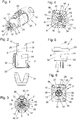
- the male connector 2 of the connector 1 according to the invention shown here by way of example is in this example a cable connector and in Fig. 1 in a perspective and in Fig. 2 shown in a side view.
- Fig. 3 shows a view in the direction in the insertion extension 4 of this male connector 2 inside.
- the corresponding female connector 3 is formed as a so-called chassis socket or as a so-called chassis connector, which is intended to be attached to the housing of an electrical appliance.
- an inventive female connector 3 as the male connector 2 shown here could also be designed as a cable connector, without this would have to be changed to something essential to the invention components. this applies the other way round also for the male connector 2.
- this could basically be designed as a chassis connector.
- the female connector 3 shown here can be screwed or otherwise secured by means of the mounting holes 36 in the flange 33 in a conventional manner to the housing of the electrical appliance.
- Fig. 4 shows a perspective view of this female connector 3
- Fig. 5 a side view.
- Fig. 6 shows a view into the Einsteckfortsatzareainnenraum 11 of this female connector 3 and its Einsteckfortsatz technique. 8
- the male connector 2 has, as is known, a housing 29 through which the insertion extension 4 projects.
- the cable grommet 31 through which an electrical cable in the male connector 2 can be introduced in a conventional manner and contacted there to the electrical contacts 6 of the insertion extension 4 and male connector 2 .
- a known slide 30, which is provided for releasing a lock formed as in the prior art.
- the housing 29, the cable grommet 31 and the slider 30 are ultimately not relevant to the invention and, as well as the inner workings of the housing 29 and the cable grommet 31, as known in the art, be executed.
- the insertion extension 4 has a Einsteckfortsatzmantelwand 5, which is formed in the embodiment shown, apart from the arranged and outwardly projecting projections 12 Vietnamesezylindermantelelförmig, so in particular a circular cylindrical jacket-shaped outer surface 25 has.
- a total of 4 projections 12 are arranged projecting outwardly on this outer surface 25.
- These four projections 12 differ in their shape and also in their position. As already mentioned, it may also be 12 more or less and differently shaped and differently arranged projections. Equally well could be in the Einsteckfortsatzmantelwand 5 corresponding receiving slots 13, if the corresponding protrusions 12 were formed in the Einsteckfortsatzabilitymantelwand 9 of the insertion extension 4 of the female connector 3.
- Mixed forms, in which both projections 12 and receiving slots 13 are arranged both on the insertion extension jacket wall 5 and on the insertion extension receiving jacket wall 9, are conceivable.
- the Einsteckfortsatzmantelwand 5 surrounds in any case the Einsteckfortsatzinnenraum 7, in which the electrical contacts 6 are located.
- the Einsteckfortsatzmantelwand 5 is, as in the embodiment shown here, conveniently designed so long that the electrical contacts 6 are arranged in the Einsteckfortsatzinnenraum 7 completely submerged and not over this.
- the sunk arranged electrical contacts 6 are clearly visible. It can also be seen that these are arranged in this embodiment on a common circular path 23.
- the molding 15 is arranged with its outwardly facing stop surfaces 17. The shape and function of this molded part 15 and in particular its interaction with the counterpart part 16 of the female connector 3 will be explained in more detail below.
- the centrally arranged mold part 15 lies here on the longitudinal center axis 19 of the insertion extension 4 and between the electrical contacts 6.
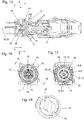
- the insertion extension receptacle wall 9 of the insertion extension receptacle 8 surrounds the insertion extension receptacle interior 11, in which the electrical mating contacts 10 are arranged.
- These electrical mating contacts 10 are all arranged on a common circular path 24 in this embodiment and arranged sunk in Einsteckfortsatzitmaschineraum 11.
- the external contacts 34 which are in conductive connection with the electrical mating contacts 10, serve to connect cables or the like and are at the rear, ie on the side facing away from the flange 33 via the housing 32 of the female connector 3 via.
- Central in Einsteckfortsatzabilityinnenraum 11 is also the Schmidtformteil invention 16 with its two Counter stop surfaces 18, the two free spaces 27 and the rotation stops 28 arranged.
- the longitudinal center axis 20 of the insertion extension receptacle 8 extends through the counterpart part 16 as well.
- the insertion extension receptacle wall 9 has a circular cylindrical inner surface 26, which in this exemplary embodiment is interrupted by the receiving slots 13. At each receiving slot 13 includes a likewise arranged in the Einsteckfortsatzareamantelwand 9, the inner surface 26 by breaking receiving channel 22 at.
- the male connector 2 is inserted with its insertion extension 4, starting from the unique, predetermined by the projections 12 and the corresponding receiving slots 13 insertion position in the insertion direction 14 in the Einsteckfortsatzation 8.
- the fully inserted position can be achieved, in which the electrical contacts 6 in this exemplary embodiment are not electrically conductively connected or contacted with the electrical mating contacts 10.
- the insertion extension 4 must first be rotated from the fully inserted position starting in the circumferential direction 21, only then comes in this embodiment, an electrical contacting of the electrical contacts 6 with the electrical Mating contacts 10.
- Fig. 7 to 10 is the fully inserted position shown, in which no electrical contact between the electrical contacts 6 and the electrical mating contacts 10 has taken place. The latter is especially good in Fig. 9 to recognize.
- FIGS. 7, 8 and 10 is also good to see that in this insertion, starting from the predetermined by the undamaged projections 12 and the corresponding receiving slots 13 unique insertion positions, the noses of the molding 15 of the insertion of 4 each penetrated into one of the here V-shaped free spaces 27 of the counter-molding 16 are, so that the stop surfaces 17 of the molding 15 at Inserting operation is not collided with the counter-abutment surfaces 18 of the counter-molding 16 or have entered into operative connection.
- the insertion extension 4 and the entire male connector 2 starting from the fully inserted position according to the Fig. 7 to 10 rotated in the circumferential direction 21.
- the projections 12 of the insertion extension are guided in the receiving channels 22 of the Einsteckfortsatzareamantelwand 9.
- the electrical contacts 6 are electrically connected to the electrical mating contacts 10, as is particularly well in the FIGS. 11 and 13 you can see.
- the Fig. 11 to 14 shown end position then the electrical contacts 6 are electrically connected to the electrical mating contacts 10, as is particularly well in the FIGS. 11 and 13 you can see.
- rotation stops 28 can be used as an additional limitation of the rotational movement in the circumferential direction 21, but need not necessarily be present.
Landscapes
- Physics & Mathematics (AREA)
- General Physics & Mathematics (AREA)
- Optics & Photonics (AREA)
- Details Of Connecting Devices For Male And Female Coupling (AREA)
- Connector Housings Or Holding Contact Members (AREA)
Priority Applications (2)
| Application Number | Priority Date | Filing Date | Title |
|---|---|---|---|
| EP19216920.9A EP3641070A1 (fr) | 2018-01-23 | 2018-11-27 | Connecteur enfichable |
| EP20202736.3A EP3787128B1 (fr) | 2018-01-23 | 2018-11-27 | Connecteur enfichable |
Applications Claiming Priority (1)
| Application Number | Priority Date | Filing Date | Title |
|---|---|---|---|
| DE102018101431.7A DE102018101431A1 (de) | 2018-01-23 | 2018-01-23 | Steckverbindung |
Related Child Applications (3)
| Application Number | Title | Priority Date | Filing Date |
|---|---|---|---|
| EP19216920.9A Division EP3641070A1 (fr) | 2018-01-23 | 2018-11-27 | Connecteur enfichable |
| EP19216920.9A Division-Into EP3641070A1 (fr) | 2018-01-23 | 2018-11-27 | Connecteur enfichable |
| EP20202736.3A Division EP3787128B1 (fr) | 2018-01-23 | 2018-11-27 | Connecteur enfichable |
Publications (2)
| Publication Number | Publication Date |
|---|---|
| EP3514892A1 true EP3514892A1 (fr) | 2019-07-24 |
| EP3514892B1 EP3514892B1 (fr) | 2020-05-20 |
Family
ID=64500270
Family Applications (3)
| Application Number | Title | Priority Date | Filing Date |
|---|---|---|---|
| EP20202736.3A Active EP3787128B1 (fr) | 2018-01-23 | 2018-11-27 | Connecteur enfichable |
| EP19216920.9A Withdrawn EP3641070A1 (fr) | 2018-01-23 | 2018-11-27 | Connecteur enfichable |
| EP18208607.4A Active EP3514892B1 (fr) | 2018-01-23 | 2018-11-27 | Connecteur enfichable |
Family Applications Before (2)
| Application Number | Title | Priority Date | Filing Date |
|---|---|---|---|
| EP20202736.3A Active EP3787128B1 (fr) | 2018-01-23 | 2018-11-27 | Connecteur enfichable |
| EP19216920.9A Withdrawn EP3641070A1 (fr) | 2018-01-23 | 2018-11-27 | Connecteur enfichable |
Country Status (5)
| Country | Link |
|---|---|
| US (2) | US10823914B2 (fr) |
| EP (3) | EP3787128B1 (fr) |
| JP (2) | JP6705027B2 (fr) |
| CN (2) | CN110071397B (fr) |
| DE (1) | DE102018101431A1 (fr) |
Families Citing this family (5)
| Publication number | Priority date | Publication date | Assignee | Title |
|---|---|---|---|---|
| US10615530B2 (en) | 2017-06-06 | 2020-04-07 | Amphenol Corporation | Spring loaded electrical connector |
| DE102018101431A1 (de) * | 2018-01-23 | 2019-07-25 | Neutrik Ag | Steckverbindung |
| CN113097790B (zh) * | 2021-04-08 | 2022-10-21 | 山东聚辰电缆有限公司 | 一种电力电缆接头及电力电缆接头的连接工艺 |
| WO2023232256A1 (fr) | 2022-06-02 | 2023-12-07 | Neutrik Ag | Connecteur intégré |
| US12580339B2 (en) | 2023-02-09 | 2026-03-17 | Amphenol Corporation | Spring loaded electrical connector |
Citations (4)
| Publication number | Priority date | Publication date | Assignee | Title |
|---|---|---|---|---|
| US3725840A (en) * | 1970-03-31 | 1973-04-03 | Staff & Schwarz Gmbh | Electrical plug and socket coupling for connecting electrical leads |
| US6394856B1 (en) * | 2000-01-04 | 2002-05-28 | Tyco Electronics Corp. | Electrical connector with programmable keying |
| US20020177373A1 (en) * | 2001-02-23 | 2002-11-28 | Olympus Optical Co., Ltd. | Connector for medical instruments |
| EP2209171A2 (fr) * | 2009-01-19 | 2010-07-21 | DDK Ltd. | Clés empêchant une fixation incorrecte et connecteur électrique l'utilisant |
Family Cites Families (39)
| Publication number | Priority date | Publication date | Assignee | Title |
|---|---|---|---|---|
| US2986612A (en) * | 1959-04-06 | 1961-05-30 | Hubbell Inc Harvey | Electrical connectors for industrial uses |
| US3351887A (en) * | 1965-06-28 | 1967-11-07 | Eldon D Jones | Interlocking electrical connection |
| US3339039A (en) * | 1965-09-10 | 1967-08-29 | Arrow Hart & Hegeman Electric | Electrical connector with contactprotecting and arc-quenching shield |
| JPH0229176U (fr) * | 1988-08-18 | 1990-02-26 | ||
| JP2779104B2 (ja) | 1992-11-12 | 1998-07-23 | 日本原子力研究所 | 簡易着脱電気コネクター |
| DE19851301C2 (de) * | 1998-11-06 | 2001-05-17 | Framatome Connectors Int | Elektrischer Steckverbinder für Zünder |
| JP2000208209A (ja) * | 1999-01-14 | 2000-07-28 | D D K Ltd | 電源接続用コネクタ |
| US6394661B1 (en) * | 1999-02-09 | 2002-05-28 | Fiber Systems International | Fiber optic connector having receptacle housing for radially aligning mating inserts |
| US6234683B1 (en) * | 1999-09-13 | 2001-05-22 | Stratos Lightwave, Inc. | Field repairable hermaphroditic connector |
| US6764351B2 (en) * | 2001-08-27 | 2004-07-20 | Campagnie Deutsch GmbH | Electrical connector |
| US7429170B2 (en) * | 2005-10-31 | 2008-09-30 | Owens-Illinois Closure Inc. | Method and machine for compression molding closure shells |
| DE102006001630A1 (de) * | 2006-01-11 | 2007-07-12 | Neutrik Aktiengesellschaft | Steckerbuchse |
| JP4557915B2 (ja) | 2006-03-24 | 2010-10-06 | 株式会社七星科学研究所 | シャッター付き電気コネクタ |
| JP4777148B2 (ja) * | 2006-05-31 | 2011-09-21 | 矢崎総業株式会社 | コネクタ |
| US20100136808A1 (en) * | 2007-03-27 | 2010-06-03 | Van-System S.R.L. | Electrical Connector |
| US7585116B2 (en) * | 2007-04-12 | 2009-09-08 | Fiber Systems International | Fiber optic connector having hermaphroditic coupling mechanism |
| US7435112B1 (en) * | 2008-02-08 | 2008-10-14 | Tyco Electronics Corporation | Electrical connector having a mechanical mating cycle limitation |
| JP4847564B2 (ja) * | 2009-07-22 | 2011-12-28 | 日本航空電子工業株式会社 | コネクタ組立体 |
| JP4925372B2 (ja) * | 2009-12-28 | 2012-04-25 | 日本航空電子工業株式会社 | 光コネクタアダプタ |
| US8550843B2 (en) * | 2010-11-22 | 2013-10-08 | Andrew Llc | Tabbed connector interface |
| JP5775335B2 (ja) * | 2011-03-16 | 2015-09-09 | 矢崎総業株式会社 | 突き当てコネクタ |
| DE102011113062A1 (de) * | 2011-09-09 | 2013-03-14 | Amphenol-Tuchel Electronics Gmbh | Kontaktgeschützter Steckverbinder |
| ES1110405Y (es) * | 2012-06-26 | 2014-08-19 | Huawei Tech Co Ltd | Conector de fibra óptica que comprende un conjunto de conector de fibra óptica y un adaptador de fibra óptica |
| JP5946377B2 (ja) * | 2012-09-07 | 2016-07-06 | 矢崎総業株式会社 | コネクタ |
| US9252539B2 (en) * | 2012-11-02 | 2016-02-02 | Hubbell Incorporated | Internally switched female receptacle or connector with plug-latching safety interlock |
| DE202013006297U1 (de) | 2013-07-11 | 2013-07-25 | Rosenberger Hochfrequenztechnik Gmbh & Co. Kg | Steckverbinder |
| US10180541B2 (en) * | 2014-12-19 | 2019-01-15 | CommScope Connectivity Belgium BVBA | Hardened fiber optic connector with pre-compressed spring |
| US9755382B2 (en) * | 2015-03-13 | 2017-09-05 | Senko Advanced Components, Inc. | Connector system with interchangeable connector modules for optical fibers, electrical conductors, or both |
| USD779434S1 (en) * | 2015-04-09 | 2017-02-21 | Neutrik Ag | Electrical connector |
| DE202015003177U1 (de) | 2015-04-30 | 2015-05-13 | Rosenberger Hochfrequenztechnik Gmbh & Co. Kg | Steckverbindung und Satz von Steckverbindungen |
| EP3391115A4 (fr) * | 2015-12-16 | 2019-07-17 | Commscope Technologies LLC | Connecteur à fibre optique installé sur le terrain |
| US9905956B2 (en) * | 2015-12-22 | 2018-02-27 | Biosense Webster (Israel) Ltd. | Preventing unwanted contact between terminals |
| US10128594B2 (en) * | 2015-12-22 | 2018-11-13 | Biosense Webster (Israel) Ltd. | Connectors having three-dimensional surfaces |
| DE102016101255A1 (de) * | 2016-01-25 | 2017-07-27 | Neutrik Ag | Verbinder |
| JP2018081144A (ja) * | 2016-11-14 | 2018-05-24 | 住友電気工業株式会社 | 光コネクタ |
| JP2019000797A (ja) * | 2017-06-14 | 2019-01-10 | 大日本印刷株式会社 | ウェブクリーナーおよびウェブクリーナーシステム |
| FR3076955B1 (fr) * | 2018-01-12 | 2020-01-31 | Marechal Electric | Socle de prise equipe d'un disque et d'un obturateur |
| DE102018101431A1 (de) * | 2018-01-23 | 2019-07-25 | Neutrik Ag | Steckverbindung |
| GB2594946B (en) * | 2020-05-12 | 2025-01-22 | Gyrus Medical Ltd | RF Shaver connector |
-
2018
- 2018-01-23 DE DE102018101431.7A patent/DE102018101431A1/de not_active Withdrawn
- 2018-11-27 EP EP20202736.3A patent/EP3787128B1/fr active Active
- 2018-11-27 EP EP19216920.9A patent/EP3641070A1/fr not_active Withdrawn
- 2018-11-27 EP EP18208607.4A patent/EP3514892B1/fr active Active
-
2019
- 2019-01-07 JP JP2019000797A patent/JP6705027B2/ja active Active
- 2019-01-11 US US16/245,751 patent/US10823914B2/en active Active
- 2019-01-23 CN CN201910063569.5A patent/CN110071397B/zh active Active
- 2019-01-23 CN CN202110187223.3A patent/CN112886338B/zh active Active
-
2020
- 2020-05-12 JP JP2020084081A patent/JP7333286B2/ja active Active
- 2020-10-13 US US17/068,968 patent/US11409050B2/en active Active
Patent Citations (4)
| Publication number | Priority date | Publication date | Assignee | Title |
|---|---|---|---|---|
| US3725840A (en) * | 1970-03-31 | 1973-04-03 | Staff & Schwarz Gmbh | Electrical plug and socket coupling for connecting electrical leads |
| US6394856B1 (en) * | 2000-01-04 | 2002-05-28 | Tyco Electronics Corp. | Electrical connector with programmable keying |
| US20020177373A1 (en) * | 2001-02-23 | 2002-11-28 | Olympus Optical Co., Ltd. | Connector for medical instruments |
| EP2209171A2 (fr) * | 2009-01-19 | 2010-07-21 | DDK Ltd. | Clés empêchant une fixation incorrecte et connecteur électrique l'utilisant |
Also Published As
| Publication number | Publication date |
|---|---|
| JP2020181818A (ja) | 2020-11-05 |
| EP3787128A1 (fr) | 2021-03-03 |
| CN112886338A (zh) | 2021-06-01 |
| JP6705027B2 (ja) | 2020-06-03 |
| CN110071397B (zh) | 2021-02-05 |
| US20210026079A1 (en) | 2021-01-28 |
| CN110071397A (zh) | 2019-07-30 |
| EP3641070A1 (fr) | 2020-04-22 |
| CN112886338B (zh) | 2023-05-09 |
| US20190227239A1 (en) | 2019-07-25 |
| DE102018101431A1 (de) | 2019-07-25 |
| US10823914B2 (en) | 2020-11-03 |
| US11409050B2 (en) | 2022-08-09 |
| EP3787128B1 (fr) | 2024-07-17 |
| EP3514892B1 (fr) | 2020-05-20 |
| JP2019129148A (ja) | 2019-08-01 |
| JP7333286B2 (ja) | 2023-08-24 |
Similar Documents
| Publication | Publication Date | Title |
|---|---|---|
| DE102006016882B4 (de) | Steckverbinder | |
| EP3514892B1 (fr) | Connecteur enfichable | |
| EP3057183B1 (fr) | Connecteur étanche | |
| EP3516741B1 (fr) | Connecteur doté d'une protection | |
| EP2517313B1 (fr) | Système de connexion par connecteur pour connexion électrique enfichable protégée contre l'humidité | |
| DE102015015202B4 (de) | Steckverbinder und Stecksystem | |
| EP2777096A1 (fr) | Unité de connexion à fiches multipolaire pour systèmes électriques triphasés | |
| DE102015201089A1 (de) | Zwischengehäuse mit einer CPA-Aufnahme und Steckverbindersysteme umfassend ein solches | |
| EP3713018B1 (fr) | Connecteur enfichable électrique | |
| DE102018124876A1 (de) | Sekundärsicherung, elektrischer Steckverbinder und elektrische Steckverbindung | |
| DE102014103864A1 (de) | Steckvorrichtungsmontage in Elektrofahrzeugen | |
| EP3386033A1 (fr) | Corps isolant d'une unité de connecteur | |
| EP3358682B1 (fr) | Connecteur électrique à fiches et système de connecteur électrique à fiches | |
| EP3170230B1 (fr) | Système de sortie de boîtier modulaire | |
| EP2599164B1 (fr) | Connecteur doté de pinces coupantes et d'un corps isolant imperdable | |
| DE112016000324T5 (de) | Verbinder | |
| DE1160523B (de) | Elektrische Steckverbindung | |
| EP3306755B1 (fr) | Direct connecteur muni de pions de codage amovibles | |
| DE60102546T2 (de) | Elektrischer Verbinder | |
| DE10213990B4 (de) | Elektrische Anschluss- oder Verbindungsklemme | |
| EP3954002A1 (fr) | Fiche de décharge pour un accumulateur d'une bicyclette électrique | |
| DE19642390B4 (de) | Elektrischer Stecker mit einem Aufnahmegehäuse und einem Kammerblock | |
| EP4507133A1 (fr) | Connecteur électrique implantable | |
| EP1209768A2 (fr) | Dispositif de connexion ou de jonction de câbles | |
| EP2760085A1 (fr) | Module adaptateur enfichable et son procédé de fabrication |
Legal Events
| Date | Code | Title | Description |
|---|---|---|---|
| PUAI | Public reference made under article 153(3) epc to a published international application that has entered the european phase |
Free format text: ORIGINAL CODE: 0009012 |
|
| STAA | Information on the status of an ep patent application or granted ep patent |
Free format text: STATUS: THE APPLICATION HAS BEEN PUBLISHED |
|
| AK | Designated contracting states |
Kind code of ref document: A1 Designated state(s): AL AT BE BG CH CY CZ DE DK EE ES FI FR GB GR HR HU IE IS IT LI LT LU LV MC MK MT NL NO PL PT RO RS SE SI SK SM TR |
|
| AX | Request for extension of the european patent |
Extension state: BA ME |
|
| STAA | Information on the status of an ep patent application or granted ep patent |
Free format text: STATUS: REQUEST FOR EXAMINATION WAS MADE |
|
| 17P | Request for examination filed |
Effective date: 20190927 |
|
| RBV | Designated contracting states (corrected) |
Designated state(s): AL AT BE BG CH CY CZ DE DK EE ES FI FR GB GR HR HU IE IS IT LI LT LU LV MC MK MT NL NO PL PT RO RS SE SI SK SM TR |
|
| GRAP | Despatch of communication of intention to grant a patent |
Free format text: ORIGINAL CODE: EPIDOSNIGR1 |
|
| STAA | Information on the status of an ep patent application or granted ep patent |
Free format text: STATUS: GRANT OF PATENT IS INTENDED |
|
| GRAS | Grant fee paid |
Free format text: ORIGINAL CODE: EPIDOSNIGR3 |
|
| RIC1 | Information provided on ipc code assigned before grant |
Ipc: H01R 13/64 20060101AFI20191112BHEP Ipc: H01R 13/71 20060101ALN20191112BHEP Ipc: H01R 13/625 20060101ALN20191112BHEP |
|
| INTG | Intention to grant announced |
Effective date: 20191127 |
|
| GRAJ | Information related to disapproval of communication of intention to grant by the applicant or resumption of examination proceedings by the epo deleted |
Free format text: ORIGINAL CODE: EPIDOSDIGR1 |
|
| GRAL | Information related to payment of fee for publishing/printing deleted |
Free format text: ORIGINAL CODE: EPIDOSDIGR3 |
|
| STAA | Information on the status of an ep patent application or granted ep patent |
Free format text: STATUS: REQUEST FOR EXAMINATION WAS MADE |
|
| GRAR | Information related to intention to grant a patent recorded |
Free format text: ORIGINAL CODE: EPIDOSNIGR71 |
|
| STAA | Information on the status of an ep patent application or granted ep patent |
Free format text: STATUS: GRANT OF PATENT IS INTENDED |
|
| INTC | Intention to grant announced (deleted) | ||
| RIC1 | Information provided on ipc code assigned before grant |
Ipc: H01R 13/71 20060101ALN20200108BHEP Ipc: H01R 13/625 20060101ALN20200108BHEP Ipc: H01R 13/64 20060101AFI20200108BHEP |
|
| RIN1 | Information on inventor provided before grant (corrected) |
Inventor name: DOBLER, OLIVER |
|
| INTG | Intention to grant announced |
Effective date: 20200124 |
|
| GRAA | (expected) grant |
Free format text: ORIGINAL CODE: 0009210 |
|
| STAA | Information on the status of an ep patent application or granted ep patent |
Free format text: STATUS: THE PATENT HAS BEEN GRANTED |
|
| AK | Designated contracting states |
Kind code of ref document: B1 Designated state(s): AL AT BE BG CH CY CZ DE DK EE ES FI FR GB GR HR HU IE IS IT LI LT LU LV MC MK MT NL NO PL PT RO RS SE SI SK SM TR |
|
| REG | Reference to a national code |
Ref country code: GB Ref legal event code: FG4D Free format text: NOT ENGLISH |
|
| REG | Reference to a national code |
Ref country code: CH Ref legal event code: EP |
|
| REG | Reference to a national code |
Ref country code: DE Ref legal event code: R096 Ref document number: 502018001485 Country of ref document: DE |
|
| REG | Reference to a national code |
Ref country code: AT Ref legal event code: REF Ref document number: 1273235 Country of ref document: AT Kind code of ref document: T Effective date: 20200615 |
|
| REG | Reference to a national code |
Ref country code: CH Ref legal event code: NV Representative=s name: ALDO ROEMPLER PATENTANWALT, CH |
|
| REG | Reference to a national code |
Ref country code: LT Ref legal event code: MG4D |
|
| REG | Reference to a national code |
Ref country code: NL Ref legal event code: MP Effective date: 20200520 |
|
| PG25 | Lapsed in a contracting state [announced via postgrant information from national office to epo] |
Ref country code: IS Free format text: LAPSE BECAUSE OF FAILURE TO SUBMIT A TRANSLATION OF THE DESCRIPTION OR TO PAY THE FEE WITHIN THE PRESCRIBED TIME-LIMIT Effective date: 20200920 Ref country code: PT Free format text: LAPSE BECAUSE OF FAILURE TO SUBMIT A TRANSLATION OF THE DESCRIPTION OR TO PAY THE FEE WITHIN THE PRESCRIBED TIME-LIMIT Effective date: 20200921 Ref country code: FI Free format text: LAPSE BECAUSE OF FAILURE TO SUBMIT A TRANSLATION OF THE DESCRIPTION OR TO PAY THE FEE WITHIN THE PRESCRIBED TIME-LIMIT Effective date: 20200520 Ref country code: SE Free format text: LAPSE BECAUSE OF FAILURE TO SUBMIT A TRANSLATION OF THE DESCRIPTION OR TO PAY THE FEE WITHIN THE PRESCRIBED TIME-LIMIT Effective date: 20200520 Ref country code: LT Free format text: LAPSE BECAUSE OF FAILURE TO SUBMIT A TRANSLATION OF THE DESCRIPTION OR TO PAY THE FEE WITHIN THE PRESCRIBED TIME-LIMIT Effective date: 20200520 Ref country code: NO Free format text: LAPSE BECAUSE OF FAILURE TO SUBMIT A TRANSLATION OF THE DESCRIPTION OR TO PAY THE FEE WITHIN THE PRESCRIBED TIME-LIMIT Effective date: 20200820 Ref country code: GR Free format text: LAPSE BECAUSE OF FAILURE TO SUBMIT A TRANSLATION OF THE DESCRIPTION OR TO PAY THE FEE WITHIN THE PRESCRIBED TIME-LIMIT Effective date: 20200821 |
|
| PG25 | Lapsed in a contracting state [announced via postgrant information from national office to epo] |
Ref country code: BG Free format text: LAPSE BECAUSE OF FAILURE TO SUBMIT A TRANSLATION OF THE DESCRIPTION OR TO PAY THE FEE WITHIN THE PRESCRIBED TIME-LIMIT Effective date: 20200820 Ref country code: RS Free format text: LAPSE BECAUSE OF FAILURE TO SUBMIT A TRANSLATION OF THE DESCRIPTION OR TO PAY THE FEE WITHIN THE PRESCRIBED TIME-LIMIT Effective date: 20200520 Ref country code: LV Free format text: LAPSE BECAUSE OF FAILURE TO SUBMIT A TRANSLATION OF THE DESCRIPTION OR TO PAY THE FEE WITHIN THE PRESCRIBED TIME-LIMIT Effective date: 20200520 Ref country code: HR Free format text: LAPSE BECAUSE OF FAILURE TO SUBMIT A TRANSLATION OF THE DESCRIPTION OR TO PAY THE FEE WITHIN THE PRESCRIBED TIME-LIMIT Effective date: 20200520 |
|
| PG25 | Lapsed in a contracting state [announced via postgrant information from national office to epo] |
Ref country code: NL Free format text: LAPSE BECAUSE OF FAILURE TO SUBMIT A TRANSLATION OF THE DESCRIPTION OR TO PAY THE FEE WITHIN THE PRESCRIBED TIME-LIMIT Effective date: 20200520 Ref country code: AL Free format text: LAPSE BECAUSE OF FAILURE TO SUBMIT A TRANSLATION OF THE DESCRIPTION OR TO PAY THE FEE WITHIN THE PRESCRIBED TIME-LIMIT Effective date: 20200520 |
|
| PG25 | Lapsed in a contracting state [announced via postgrant information from national office to epo] |
Ref country code: DK Free format text: LAPSE BECAUSE OF FAILURE TO SUBMIT A TRANSLATION OF THE DESCRIPTION OR TO PAY THE FEE WITHIN THE PRESCRIBED TIME-LIMIT Effective date: 20200520 Ref country code: ES Free format text: LAPSE BECAUSE OF FAILURE TO SUBMIT A TRANSLATION OF THE DESCRIPTION OR TO PAY THE FEE WITHIN THE PRESCRIBED TIME-LIMIT Effective date: 20200520 Ref country code: SM Free format text: LAPSE BECAUSE OF FAILURE TO SUBMIT A TRANSLATION OF THE DESCRIPTION OR TO PAY THE FEE WITHIN THE PRESCRIBED TIME-LIMIT Effective date: 20200520 Ref country code: EE Free format text: LAPSE BECAUSE OF FAILURE TO SUBMIT A TRANSLATION OF THE DESCRIPTION OR TO PAY THE FEE WITHIN THE PRESCRIBED TIME-LIMIT Effective date: 20200520 Ref country code: CZ Free format text: LAPSE BECAUSE OF FAILURE TO SUBMIT A TRANSLATION OF THE DESCRIPTION OR TO PAY THE FEE WITHIN THE PRESCRIBED TIME-LIMIT Effective date: 20200520 Ref country code: RO Free format text: LAPSE BECAUSE OF FAILURE TO SUBMIT A TRANSLATION OF THE DESCRIPTION OR TO PAY THE FEE WITHIN THE PRESCRIBED TIME-LIMIT Effective date: 20200520 Ref country code: IT Free format text: LAPSE BECAUSE OF FAILURE TO SUBMIT A TRANSLATION OF THE DESCRIPTION OR TO PAY THE FEE WITHIN THE PRESCRIBED TIME-LIMIT Effective date: 20200520 |
|
| REG | Reference to a national code |
Ref country code: DE Ref legal event code: R097 Ref document number: 502018001485 Country of ref document: DE |
|
| PG25 | Lapsed in a contracting state [announced via postgrant information from national office to epo] |
Ref country code: PL Free format text: LAPSE BECAUSE OF FAILURE TO SUBMIT A TRANSLATION OF THE DESCRIPTION OR TO PAY THE FEE WITHIN THE PRESCRIBED TIME-LIMIT Effective date: 20200520 Ref country code: SK Free format text: LAPSE BECAUSE OF FAILURE TO SUBMIT A TRANSLATION OF THE DESCRIPTION OR TO PAY THE FEE WITHIN THE PRESCRIBED TIME-LIMIT Effective date: 20200520 |
|
| REG | Reference to a national code |
Ref country code: CH Ref legal event code: NV Representative=s name: ABP PATENT NETWORK AG, CH |
|
| REG | Reference to a national code |
Ref country code: DE Ref legal event code: R082 Ref document number: 502018001485 Country of ref document: DE Representative=s name: ABP BURGER RECHTSANWALTSGESELLSCHAFT MBH, DE Ref country code: DE Ref legal event code: R082 Ref document number: 502018001485 Country of ref document: DE Representative=s name: KAMINSKI HARMANN PATENTANWAELTE AG, LI |
|
| PLBE | No opposition filed within time limit |
Free format text: ORIGINAL CODE: 0009261 |
|
| STAA | Information on the status of an ep patent application or granted ep patent |
Free format text: STATUS: NO OPPOSITION FILED WITHIN TIME LIMIT |
|
| 26N | No opposition filed |
Effective date: 20210223 |
|
| PG25 | Lapsed in a contracting state [announced via postgrant information from national office to epo] |
Ref country code: SI Free format text: LAPSE BECAUSE OF FAILURE TO SUBMIT A TRANSLATION OF THE DESCRIPTION OR TO PAY THE FEE WITHIN THE PRESCRIBED TIME-LIMIT Effective date: 20200520 |
|
| PG25 | Lapsed in a contracting state [announced via postgrant information from national office to epo] |
Ref country code: MC Free format text: LAPSE BECAUSE OF FAILURE TO SUBMIT A TRANSLATION OF THE DESCRIPTION OR TO PAY THE FEE WITHIN THE PRESCRIBED TIME-LIMIT Effective date: 20200520 |
|
| PG25 | Lapsed in a contracting state [announced via postgrant information from national office to epo] |
Ref country code: LU Free format text: LAPSE BECAUSE OF NON-PAYMENT OF DUE FEES Effective date: 20201127 |
|
| REG | Reference to a national code |
Ref country code: BE Ref legal event code: MM Effective date: 20201130 |
|
| PG25 | Lapsed in a contracting state [announced via postgrant information from national office to epo] |
Ref country code: IE Free format text: LAPSE BECAUSE OF NON-PAYMENT OF DUE FEES Effective date: 20201127 |
|
| PG25 | Lapsed in a contracting state [announced via postgrant information from national office to epo] |
Ref country code: MT Free format text: LAPSE BECAUSE OF FAILURE TO SUBMIT A TRANSLATION OF THE DESCRIPTION OR TO PAY THE FEE WITHIN THE PRESCRIBED TIME-LIMIT Effective date: 20200520 Ref country code: CY Free format text: LAPSE BECAUSE OF FAILURE TO SUBMIT A TRANSLATION OF THE DESCRIPTION OR TO PAY THE FEE WITHIN THE PRESCRIBED TIME-LIMIT Effective date: 20200520 |
|
| PG25 | Lapsed in a contracting state [announced via postgrant information from national office to epo] |
Ref country code: MK Free format text: LAPSE BECAUSE OF FAILURE TO SUBMIT A TRANSLATION OF THE DESCRIPTION OR TO PAY THE FEE WITHIN THE PRESCRIBED TIME-LIMIT Effective date: 20200520 |
|
| PG25 | Lapsed in a contracting state [announced via postgrant information from national office to epo] |
Ref country code: BE Free format text: LAPSE BECAUSE OF NON-PAYMENT OF DUE FEES Effective date: 20201130 |
|
| REG | Reference to a national code |
Ref country code: DE Ref legal event code: R082 Ref document number: 502018001485 Country of ref document: DE Representative=s name: KAMINSKI HARMANN PATENTANWAELTE AG, LI |
|
| REG | Reference to a national code |
Ref country code: DE Ref legal event code: R082 Ref document number: 502018001485 Country of ref document: DE Representative=s name: KAMINSKI HARMANN PATENTANWAELTE AG, LI |
|
| PGFP | Annual fee paid to national office [announced via postgrant information from national office to epo] |
Ref country code: CH Payment date: 20231202 Year of fee payment: 6 |
|
| REG | Reference to a national code |
Ref country code: CH Ref legal event code: PL |
|
| REG | Reference to a national code |
Ref country code: CH Ref legal event code: PL |
|
| PG25 | Lapsed in a contracting state [announced via postgrant information from national office to epo] |
Ref country code: CH Free format text: LAPSE BECAUSE OF NON-PAYMENT OF DUE FEES Effective date: 20241130 |
|
| PGFP | Annual fee paid to national office [announced via postgrant information from national office to epo] |
Ref country code: DE Payment date: 20251119 Year of fee payment: 8 |
|
| PGFP | Annual fee paid to national office [announced via postgrant information from national office to epo] |
Ref country code: GB Payment date: 20251121 Year of fee payment: 8 |
|
| PGFP | Annual fee paid to national office [announced via postgrant information from national office to epo] |
Ref country code: AT Payment date: 20251120 Year of fee payment: 8 |
|
| PGFP | Annual fee paid to national office [announced via postgrant information from national office to epo] |
Ref country code: FR Payment date: 20251126 Year of fee payment: 8 |
|
| PGFP | Annual fee paid to national office [announced via postgrant information from national office to epo] |
Ref country code: TR Payment date: 20251119 Year of fee payment: 8 |