EP3515076B1 - Verfahren und vorrichtung zur bewegungskompensationsvorhersage - Google Patents
Verfahren und vorrichtung zur bewegungskompensationsvorhersage Download PDFInfo
- Publication number
- EP3515076B1 EP3515076B1 EP17854950.7A EP17854950A EP3515076B1 EP 3515076 B1 EP3515076 B1 EP 3515076B1 EP 17854950 A EP17854950 A EP 17854950A EP 3515076 B1 EP3515076 B1 EP 3515076B1
- Authority
- EP
- European Patent Office
- Prior art keywords
- pixel
- location
- image
- value
- current
- Prior art date
- Legal status (The legal status is an assumption and is not a legal conclusion. Google has not performed a legal analysis and makes no representation as to the accuracy of the status listed.)
- Active
Links
Images









Classifications
-
- H—ELECTRICITY
- H04—ELECTRIC COMMUNICATION TECHNIQUE
- H04N—PICTORIAL COMMUNICATION, e.g. TELEVISION
- H04N19/00—Methods or arrangements for coding, decoding, compressing or decompressing digital video signals
- H04N19/50—Methods or arrangements for coding, decoding, compressing or decompressing digital video signals using predictive coding
- H04N19/503—Methods or arrangements for coding, decoding, compressing or decompressing digital video signals using predictive coding involving temporal prediction
- H04N19/51—Motion estimation or motion compensation
- H04N19/513—Processing of motion vectors
- H04N19/517—Processing of motion vectors by encoding
- H04N19/52—Processing of motion vectors by encoding by predictive encoding
-
- H—ELECTRICITY
- H04—ELECTRIC COMMUNICATION TECHNIQUE
- H04N—PICTORIAL COMMUNICATION, e.g. TELEVISION
- H04N19/00—Methods or arrangements for coding, decoding, compressing or decompressing digital video signals
- H04N19/10—Methods or arrangements for coding, decoding, compressing or decompressing digital video signals using adaptive coding
- H04N19/102—Methods or arrangements for coding, decoding, compressing or decompressing digital video signals using adaptive coding characterised by the element, parameter or selection affected or controlled by the adaptive coding
- H04N19/103—Selection of coding mode or of prediction mode
- H04N19/105—Selection of the reference unit for prediction within a chosen coding or prediction mode, e.g. adaptive choice of position and number of pixels used for prediction
-
- H—ELECTRICITY
- H04—ELECTRIC COMMUNICATION TECHNIQUE
- H04N—PICTORIAL COMMUNICATION, e.g. TELEVISION
- H04N19/00—Methods or arrangements for coding, decoding, compressing or decompressing digital video signals
- H04N19/10—Methods or arrangements for coding, decoding, compressing or decompressing digital video signals using adaptive coding
- H04N19/134—Methods or arrangements for coding, decoding, compressing or decompressing digital video signals using adaptive coding characterised by the element, parameter or criterion affecting or controlling the adaptive coding
- H04N19/167—Position within a video image, e.g. region of interest [ROI]
-
- H—ELECTRICITY
- H04—ELECTRIC COMMUNICATION TECHNIQUE
- H04N—PICTORIAL COMMUNICATION, e.g. TELEVISION
- H04N19/00—Methods or arrangements for coding, decoding, compressing or decompressing digital video signals
- H04N19/10—Methods or arrangements for coding, decoding, compressing or decompressing digital video signals using adaptive coding
- H04N19/169—Methods or arrangements for coding, decoding, compressing or decompressing digital video signals using adaptive coding characterised by the coding unit, i.e. the structural portion or semantic portion of the video signal being the object or the subject of the adaptive coding
- H04N19/17—Methods or arrangements for coding, decoding, compressing or decompressing digital video signals using adaptive coding characterised by the coding unit, i.e. the structural portion or semantic portion of the video signal being the object or the subject of the adaptive coding the unit being an image region, e.g. an object
- H04N19/176—Methods or arrangements for coding, decoding, compressing or decompressing digital video signals using adaptive coding characterised by the coding unit, i.e. the structural portion or semantic portion of the video signal being the object or the subject of the adaptive coding the unit being an image region, e.g. an object the region being a block, e.g. a macroblock
-
- H—ELECTRICITY
- H04—ELECTRIC COMMUNICATION TECHNIQUE
- H04N—PICTORIAL COMMUNICATION, e.g. TELEVISION
- H04N19/00—Methods or arrangements for coding, decoding, compressing or decompressing digital video signals
- H04N19/10—Methods or arrangements for coding, decoding, compressing or decompressing digital video signals using adaptive coding
- H04N19/169—Methods or arrangements for coding, decoding, compressing or decompressing digital video signals using adaptive coding characterised by the coding unit, i.e. the structural portion or semantic portion of the video signal being the object or the subject of the adaptive coding
- H04N19/182—Methods or arrangements for coding, decoding, compressing or decompressing digital video signals using adaptive coding characterised by the coding unit, i.e. the structural portion or semantic portion of the video signal being the object or the subject of the adaptive coding the unit being a pixel
-
- H—ELECTRICITY
- H04—ELECTRIC COMMUNICATION TECHNIQUE
- H04N—PICTORIAL COMMUNICATION, e.g. TELEVISION
- H04N19/00—Methods or arrangements for coding, decoding, compressing or decompressing digital video signals
- H04N19/50—Methods or arrangements for coding, decoding, compressing or decompressing digital video signals using predictive coding
- H04N19/503—Methods or arrangements for coding, decoding, compressing or decompressing digital video signals using predictive coding involving temporal prediction
- H04N19/51—Motion estimation or motion compensation
- H04N19/547—Motion estimation performed in a transform domain
-
- H—ELECTRICITY
- H04—ELECTRIC COMMUNICATION TECHNIQUE
- H04N—PICTORIAL COMMUNICATION, e.g. TELEVISION
- H04N19/00—Methods or arrangements for coding, decoding, compressing or decompressing digital video signals
- H04N19/50—Methods or arrangements for coding, decoding, compressing or decompressing digital video signals using predictive coding
- H04N19/597—Methods or arrangements for coding, decoding, compressing or decompressing digital video signals using predictive coding specially adapted for multi-view video sequence encoding
-
- H—ELECTRICITY
- H04—ELECTRIC COMMUNICATION TECHNIQUE
- H04N—PICTORIAL COMMUNICATION, e.g. TELEVISION
- H04N19/00—Methods or arrangements for coding, decoding, compressing or decompressing digital video signals
- H04N19/85—Methods or arrangements for coding, decoding, compressing or decompressing digital video signals using pre-processing or post-processing specially adapted for video compression
Definitions
- This application relates to the image processing field, and more specifically, to a motion-compensated prediction method and device.
- a spherical panoramic image (a spherical image for short) is processed
- the spherical image is first projected to a two-dimensional planar panoramic image (a two-dimensional image for short) in a polyhedral format, and then encoding and decoding operations are performed on the two-dimensional image in the polyhedral format.
- motion-compensated prediction is performed for the two-dimensional image in the polyhedral format, generally, a location of a reference pixel of a current pixel is first determined, and then a pixel value of the current pixel is predicted based on a pixel value of the reference pixel.
- a motion-compensated prediction process in the prior art regardless of whether the reference pixel is located on a face on which the current pixel is located, the pixel value of the current pixel is predicted based on the pixel value at a location of the reference pixel.
- cubic-panorama datasets are treated as planar image sequences with a rectangular support. In this way, it is inevitable to sacrifice some coding efficiency because of the inconsistency on the boundaries of connected side images.
- MCTF motion-compensated temporal filtering
- Specific approaches for constructing the reference blocks on the corners of cubes are designed for motion estimation.
- the search for motion vectors in reference frames can be naturally extended across side-image boundaries into neighbor side images.
- the spatially consistent representation of cubic panoramas eliminates image boundary constraints for motion vector search.
- the search for motion vectors as well as matching reference blocks can be extended well beyond the side image boundaries in all four directions.
- the compression scheme is adapted to the features of cubic-panorama datasets.
- the experimental results of applying the proposed compression scheme to coding sample cubic-panorama datasets are presented. It is shown that superior coding performance is achieved with the spatially consistent representation compared with the generic representation of cubic-panorama datasets.
- This application provides a motion-compensated prediction method and a motion-compensated prediction apparatus, to improve a motion-compensated prediction effect.
- the invention is defined in the appended set of claims.
- the target reference pixel that can really play a reference role is found based on the location of the initial reference pixel, and then the pixel value of the current pixel is predicted based on the target reference pixel, thereby improving accuracy of motion-compensated prediction.
- a virtual reality (Virtual Reality, VR) video image usually includes 360-degree omnidirectional visual information in three-dimensional space, and the VR video image may be imagined as a map obtained by viewing a globe from an internal center location of the globe.
- the VR video image may also be referred to as a panoramic video image (which may be briefly referred to as a spherical image).
- the spherical image cannot be conveniently represented, stored, or indexed, before the spherical image is processed, the spherical image usually needs to be spread to obtain a two-dimensional image, and then operations such as compression, processing, storage, and transmission are performed on the two-dimensional image.
- a process of spreading the spherical image to obtain the two-dimensional image is referred to as projection.
- a common two-dimensional image is referred to as a longitude and latitude map.
- images in regions adjacent to the South Pole and the North Pole are stretched to a large extent, and therefore severe distortion and data redundancy exist.
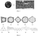
- a spherical image may be projected to a polyhedron, to convert the spherical image into a two-dimensional image in a polyhedral format.
- the spherical image may be projected to a regular tetrahedron ((a) in FIG. 2 ), a regular hexahedron ((b) in FIG. 2 ), a regular octahedron ((c) in FIG. 2 ), a regular dodecahedron ((d) in FIG. 2 ), and a regular icosahedron ((e) in FIG. 2 ), and two-dimensional planar images obtained by projecting the spherical image to all the polyhedrons are successively shown in (f) to (k) in FIG. 2 .
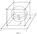
- a specific process of projecting the spherical image to the polyhedron is as follows: The spherical image is placed in the polyhedron, so that the spherical image becomes a sphere that is internally tangent to the polyhedron; a sphere center or a body center of the polyhedron and a point on a spherical surface are connected, and the connection line is prolonged to be intersected with the polyhedron; and a pixel at a location of the intersection point on the polyhedron is a pixel of a corresponding point in the spherical image.
- a process of projecting a spherical image to a regular hexahedron is used as an example below.
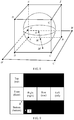
- the spherical image is internally tangent to the regular hexahedron ABCDEFGH.
- a sphere center O and M' are connected, and the connection line is intersected with a point M on a spherical surface.
- a pixel at the point M is a pixel at the point M'.
- all pixels in a region ABCD on a plane A'B'C'D' may be obtained by using the same method.
- the pixels in the region ABCD form a face (face) ABCD
- the plane A'B'C'D' is a projection plane (projection plane) of the face ABCD.
- an image of each face on the surface of the polyhedron becomes an image of a region in the two-dimensional image or a sub-image in the spherical image.
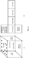
- a surface of a regular hexahedron in (a) in FIG. 4 is spread to obtain an image in (b) in FIG. 4
- a face image of a top face on the surface of the hexahedron becomes a sub-image in an upper left corner in (b) in FIG. 4 .
- the sub-image is referred to as the face image of the top face in the regular hexahedron image, and the top face in the spherical image is a region covered by the face image of the top face.
- the top face is referred to as a face on which the pixel is located.
- a face in the embodiments of this application is corresponding to a sub-image.
- a bottom face is a face in a two-dimensional image
- an image of the bottom face is a first sub-image
- the bottom face is a face corresponding to the first sub-image
- the first sub-image is a sub-image corresponding to the bottom face.
- each small rectangular region is a face in a two-dimensional image
- an image formed by pixels in each rectangular region is a sub-image in the two-dimensional image, that is, the face is a concept of a region
- the sub-image is an image.
- images shown in (f) to (k) in FIG. 2 may be directly processed, or an image in a rectangular region with a minimum size enclosed by the two-dimensional image may be selected as a processing object, and the rectangular region except a region including a face in the two-dimensional image is filled with default content or the like, for example, all gray, all black, or all white.
- Unidirectional prediction and bidirectional prediction may be included based on a reference direction. Unidirectional prediction means that the current block has one reference image set (an element in the set is a reference image selected from reconstructed images), and any reference image in the set may be selected for a coding block.
- Bidirectional prediction means that the current block has two reference image sets (elements in the two sets are separately images independently selected from reconstructed images, and reference images in the two sets may be partially or all the same), and a reference image in each of the two sets may be selected for a coding block.
- using unidirectional prediction or bidirectional prediction and a method for constructing a reference image set are jointly agreed on between an encoder side and a decoder side, or an encoder side transmits a used method to a decoder side, and the decoder side determines the used method based on a decoding result.
- the bidirectional prediction method is used, the current coding block has two reference blocks, and each reference block needs to be indicated by motion information of the reference block.
- the decoder side needs to determine the two reference blocks based on the two pieces of motion information obtained through decoding, and determines a prediction value of a pixel value of a pixel in the current block based on pixel values of pixels in the two reference blocks.
- a reference pixel that is of a current pixel in the current block and that is in the reference block is determined, and then a prediction value of a pixel value of the current pixel is predicted based on a pixel value of the reference pixel.
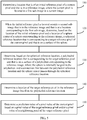
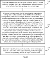
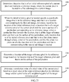
- FIG. 5 is a schematic flowchart of a motion-compensated prediction method according to an embodiment of this application. The method includes the following steps.
- the current image and the reference image each are a two-dimensional image that is in a polyhedral format and is obtained by converting a spherical image.
- the current image when prediction processing is performed for the current image, the current image may be divided into a plurality of image blocks, and then each image block is processed.
- the foregoing current pixel may be a pixel in an image block in the current image.
- the to-be-processed current pixel may be located in an image block in the first sub-image.
- a decoder may determine the location of the initial reference pixel in the reference image based on a location of the current pixel and motion information of the current pixel that is obtained by decoding a motion information bitstream. For example, the decoder determines the reference image based on reference image indication information in the motion information, and determines the location of the initial reference pixel in the reference image based on motion vector information in the motion information and the location of the current pixel.
- a location of a current pixel is the location of the initial reference pixel.
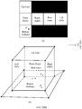
- a polyhedron corresponding to each of the current image and the reference image is a regular hexahedron, where (a) in FIG. 6 shows the current image (the current pixel is in the current image), and (b) in FIG. 6 shows the reference image (the initial reference pixel is in the reference image).
- the current image and the reference image each include six sub-images.
- the six sub-images are respectively a top (top) sub-image, a front (front) sub-image, a right (right) sub-image, a rear (rear) sub-image, a left (left) sub-image, and a bottom (bottom) sub-image.
- the sub-image herein may be considered as an array including some pixels, and these pixels are on a same projection plane when a spherical image is projected to the polyhedron. After the polyhedron is spread to obtain a two-dimensional image, each face of the polyhedron becomes a part of the two-dimensional image. It is assumed that the current pixel is P and P is in the bottom sub-image in the current image. It is assumed that the initial reference pixel is T and T is in the front sub-image in the reference image, in other words, T is not in the bottom sub-image in the reference image. It should be understood that, the first sub-image is the bottom sub-image in (a) in FIG. 6 , a second sub-image is the bottom sub-image in (b) in FIG. 6 , and the first sub-image and the second sub-image are sub-images that are in the current image and the reference image and that are at corresponding locations.
- the initial reference pixel When the initial reference pixel is located outside a second sub-image that is in the reference image and that is at a location corresponding to the first sub-image, determine, based on the location of the initial reference pixel and a location of a sphere center of a sphere corresponding to the reference image, a spherical reference location that is corresponding to a target reference pixel of the current pixel and that is on a surface of the sphere.
- the spherical reference location that is corresponding to the target reference pixel and that is on the surface of the sphere may be determined based on the location of the initial reference pixel; next, the polyhedral reference location that is corresponding to the target reference pixel and that is on the surface of the polyhedron is determined based on the spherical reference location; and the location of the target reference pixel in the reference image may be determined based on the polyhedral reference location.
- the sphere and the polyhedron that are corresponding to the reference image are used, so that the location of the target reference pixel in the reference image can be determined step by step by using the spherical reference location and the polyhedral reference location.
- prediction may be performed for the current pixel directly based on the initial reference pixel, and there is no need to search for the target reference pixel.
- the polyhedron corresponding to the reference image may be a polyhedron formed by the reference image, namely, a polyhedron formed by folding all the sub-images in the reference image according to a specific rule.
- the method further includes: determining, based on layout information of the reference image and the location of the initial reference pixel, whether the initial reference pixel is located outside the second sub-image in the reference image.
- the location of the initial reference pixel in the reference image needs to be determined first.
- a specific process of determining the location of the initial reference pixel is as follows:
- the decoder may determine the location of the initial reference pixel in the reference image based on the location of the current pixel and the motion information of the current pixel that is obtained by decoding the motion information bitstream. For example, the decoder may determine the reference image based on the reference image indication information in the motion information, and determine the location of the initial reference pixel in the reference image based on the motion vector information in the motion information and the location of the current pixel.
- the location of the current pixel is the location of the initial reference pixel.
- layout information of the polyhedron corresponding to the reference image includes at least one of face quantity information of the polyhedron corresponding to the reference image, sub-image arrangement manner information of the reference image, sub-image arrangement order information of the reference image, and sub-image rotation information of the reference image.
- the face quantity information of the polyhedron corresponding to the reference image may be specifically a polyhedron corresponding to the reference image.
- the face quantity information of the polyhedron may indicate that the reference image is corresponding to a regular hexahedron.
- the sub-image arrangement manner information of the reference image means an arrangement manner of all the sub-images in the reference image.
- the reference image is corresponding to a regular hexahedron.
- the reference image includes six sub-images, and an arrangement manner of the six sub-images may be a 4 ⁇ 3 format ((b) in FIG. 7 ), a 3 ⁇ 2 format ((c) in FIG. 7 and (d) in FIG. 7 ), or a 6 ⁇ 1 format ((e) in FIG. 7 and (f) in FIG. 7 ).
- the sub-image arrangement order information of the reference image means an arrangement order, in the reference image, of all the sub-images in the reference image.
- (c) in FIG. 7 and (d) in FIG. 7 each show an image of the 3 ⁇ 2 format, where in (c) in FIG. 7 , a sub-image corresponding to a front face is arranged in a lower left corner of the image, and in (d) in FIG. 7 , a sub-image corresponding to a front face is arranged at a center location in the first column.
- the sub-image rotation information of the reference image may mean a rotation angle of a sub-image in the reference image. It is assumed that a placement location of each sub-image in (c) in FIG. 7 is used as a reference location. In this case, in (d) in FIG. 7 , a rotation angle of the sub-image corresponding to the front face is -90 degrees.
- the target reference pixel that can really play a reference role is found based on the location of the initial reference pixel, and then the pixel value of the current pixel is predicted based on the target reference pixel, thereby improving accuracy of motion-compensated prediction.
- the determining, based on the location of the initial reference pixel and a location of a sphere center of a sphere corresponding to the reference image, a spherical reference location that is corresponding to a target reference pixel of the current pixel and that is on a surface of the sphere includes:
- the offset value of the location of the initial reference pixel relative to the second sub-image may be a location offset value of the location of the initial reference pixel relative to a point (such as a center point in the second sub-image) in the second sub-image.
- the location of the initial reference pixel may be a location that is of the initial reference pixel and that is in a coordinate system of a plane on which the second sub-image is located.
- the first location may be a location that is corresponding to the initial reference pixel and that is in a coordinate system of a plane on which a first face of a polyhedron (the polyhedron is a polyhedron corresponding to the reference image) is located.
- the coordinate system of the plane on which the first face is located may be different from the coordinate system of the plane on which the second sub-image is located.
- a location that is of the initial reference pixel and that is in a coordinate system is converted into a location in another coordinate system. If the first face of the polyhedron corresponding to the reference image coincides with a face on which the second sub-image in the reference image is located, the location of the initial reference pixel coincides with the first location.
- a regular hexahedron corresponding to the reference image is ABCD-EFGH.
- a face ABCD of the regular hexahedron is corresponding to the second sub-image in the reference image.
- a plane on which the face ABCD is located is A'B'C'D'.
- a sphere corresponding to the reference image is internally tangent to the regular hexahedron ABCD-EFGH.
- a point M is a spherical reference location that is corresponding to the target reference pixel and that is on a surface of the sphere.
- a point M' is a polyhedral reference location that is corresponding to the target reference pixel and that is on the polyhedron.
- a location of the point M may be determined based on the first location (the first location is not shown in FIG. 8 ) of the initial reference pixel and a location of a sphere center O.
- a location of M' may be determined based on the location of the point M. Then, the location of the target reference pixel in the reference image may be determined based on the location of M'.
- Embodiment 1 describes in detail how to determine the spherical reference location based on the location of the initial reference pixel and the location of the sphere center of the sphere.
- the reference image is a panoramic image of a hexahedron being arranged into a 4 ⁇ 3 format plane image
- the initial reference pixel of the current pixel is T
- the current pixel is in a bottom face in the current image
- a point R is any point in a bottom face in the reference image
- a location of T and a location offset of T relative to R are already known.
- FIG. 10 shows a sphere corresponding to the reference image.
- the sphere is internally tangent to the polyhedron (the polyhedron is not shown in FIG. 10 ) corresponding to the reference image
- the sphere is tangent to a bottom face of the polyhedron
- the bottom face of the polyhedron is corresponding to the bottom face in the reference image.
- a location of T' (namely, the first location of the initial reference pixel) may be determined based on the location of T and the offset value of T relative to R.
- A'B'C'D' is the plane on which the face ABCD is located, and a space rectangular coordinate system x-y-z is established by using the sphere center of the sphere as a coordinate origin.
- a plane x-O-y is parallel to the plane A'B'C'D'
- a projection pixel of the point O on the plane A'B'C'D' is O'
- O'Q is parallel to a y-axis
- O'P is parallel to an x-axis
- PT' is perpendicular to O'P
- T'Q is perpendicular to O'Q
- ON on a plane x-O-y is parallel to O'T'
- the first location of the initial reference pixel is T'
- the spherical reference location that is corresponding to the target reference pixel and that is on the sphere is T".
- a location of the point T" on the sphere may be determined based on a location of T'.
- the location of the point T" may be determined based on the radius of the sphere, ⁇ O " ON , and ⁇ WOT ", that is, the spherical reference location that is corresponding to the target reference pixel and that is on the surface of the sphere is determined.
- the following describes in detail how to determine, based on the spherical reference location, the polyhedral reference location that is corresponding to the target reference pixel and that is on the surface of the polyhedron.
- the spherical reference location has been determined in FIG. 10 .
- the polyhedral reference location is determined based on the spherical reference location.
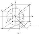
- the polyhedron corresponding to the reference image is ABCD-EFGH.
- a prism of the polyhedron is a.
- O is a body center of the polyhedron.
- O' is a projection, of O, on the face ABCD.
- J is a midpoint on an edge BC.
- T" is the spherical reference location.
- An extended line of OT" is intersected with the polyhedron at a point H and is intersected with, at a point T, the plane on which the face ABCD is located.
- K is a vertical projection, of T, on an extended line of O'J.
- S is a vertical projection, of the point H, on edge BC.
- I is a vertical projection, of T, on the edge BC.
- a location of the point H may be determined, that is, the polyhedral reference location is determined. The following describes how to determine the lengths of SJ and SH.
- the lengths of SJ and SH can be obtained from formula (5) and formula (8). In this way, the location of the point H is determined, that is, the polyhedral reference location is determined.
- L SH is determined based on L ST , L OO', and L O'T .
- L SH may also be determined according to another formula in addition to formula (8), and a specific process of determining L SH according to the another formula is as follows:
- L SH may also be determined based on L JK , L OO' , and L O'K .
- Embodiment 2 the foregoing describes in detail how to determine the polyhedral reference location when the polyhedron corresponding to the reference image is a regular hexahedron.
- Embodiment 3 and Embodiment 4 the following describes in detail how to determine the polyhedral reference location when the polyhedron corresponding to the reference image is another polyhedron.
- FIG. 12 two polyhedrons are included.
- An included angle between adjacent faces of a polyhedron in (a) in FIG. 12 is greater than 90 degrees, and an included angle between adjacent faces of a polyhedron in (b) FIG. 12 is less than 90 degrees.
- the polyhedron corresponding to the reference image includes two faces ACB and DBC.
- An included angle between the face ACB and the face DBC is greater than 90 degrees (the polyhedron may further include other faces that are not listed herein one by one).
- the face ACB is a projection plane of the face on which the second sub-image in the reference image is located.
- An edge BC is an edge on which a neighboring face and the face on which the second sub-image is located meet each other.
- J is a point at which a vertical line O'K from O' to the edge BC is intersected with the edge BC.
- An extended line of OT" is intersected with the polyhedron at a point H and is intersected with, at a point T, a plane on which the face ACB is located.
- O'T is intersected with the edge BC at a point S.
- OT is intersected with the face BCD at the point H.
- H" is a vertical projection, of H, on O'K.
- L is a vertical projection, of H", on O'K.
- a location of O' and a length of OO' are determined, and a location of J is also determined. If a length (which is equal to a length of HH") of SJ and a length of SH are determined, a location of the point H at which OT is intersected with the face BCD may be determined, that is, the polyhedral reference location that is corresponding to the target reference pixel and that is on the surface of the polyhedron is determined.
- L O ′ T L O ′ O ⁇ tan ⁇ O ′ OT
- L KT L O ′ T ⁇ sin ⁇ TO ′ K
- L JK L O ′ T ′ ⁇ cos ⁇ TO ′ K ⁇ L O ′ J
- L O ′ K L O ′ J + L JK
- SJ L O ′ J ⁇ L KT L O ′ K
- L O ′ T L O ′ K 2 + L KT 2
- L OT L O ′ O 2 + L O ′ K + L KT 2
- an included angle between a face ACB and a face DBC of the polyhedron corresponding to the reference image is less than 90 degrees.
- Embodiment 1 and Embodiment 3 how to determine the spherical reference location based on the first location and then determine the polyhedral reference location based on the spherical reference location are described in Embodiment 1 and Embodiment 3. Actually, the polyhedral reference location may also be determined directly based on the first location. With reference to Embodiment 4 and Embodiment 5, the following describes in detail how to determine the polyhedral reference location (namely, a location that is obtained by projecting the target reference pixel on the surface of the polyhedron) directly based on the first location.
- FIG. 13 shows the current image
- FIG. 13 shows the reference image
- P is the current pixel in the current image
- P is located on a bottom face in the current image
- P' is a pixel that is in the reference image and is at a same location as P
- P' is located on a bottom face in the reference image
- T 1 , T 2 , and T 3 are all initial reference pixels of the current pixel, and are all located outside the bottom face in the reference image.
- a regular hexahedron in FIG. 14 is a polyhedron that is corresponding to the reference image and is constructed by using the bottom face in the reference image as the bottom.
- FIG. 14 shows three current pixels T 1 , T 2 , and T 3 in (b) in FIG. 13 . It can be learned from FIG. 14 that, pixels that are corresponding to three target reference pixels and are on the regular hexahedron are respectively H 1 , H 2 , and H 3 .
- H 1 , H 2 , and H 3 are at locations of points at which the regular hexahedron is intersected with connection lines between a point O and T 1 , T 2 , and T 3 .
- locations of H 1 , H 2 , and H 3 can be determined based on locations of T 1 , T 2 , and T 3 . It should be understood that, in FIG. 14 , T 1 , T 2 , and T 3 show only a case in which initial reference pixels are at different locations. Actually, only one reference pixel exists at a time.
- the following uses FIG. 15 as an example to describe in detail how to determine, based on the location of the initial reference pixel, a location of a pixel that is on a polyhedron and that is corresponding to the target reference pixel.
- T 1 is used as an example to describe in detail how to determine, based on a location of T 1 , a location of a projection pixel that is obtained by projecting the target reference pixel to the surface of the polyhedron.
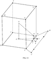
- a regular hexahedron in FIG. 15 is a polyhedron that is corresponding to the reference image and is constructed by using the bottom face in the reference image as the bottom, that is, an anchoring face (the anchoring face may be understood as the bottom during construction of the polyhedron, for example, if a face in the reference image is used as the bottom of the constructed polyhedron, the bottom is the anchoring face of the polyhedron) of the regular hexahedron is the bottom face in the reference image.
- a prism of the regular hexahedron is a.
- O is a body center of the regular hexahedron.
- a location of T is the location of the initial reference pixel.
- a face ABCD is a face on which a pixel that is in the reference image and that is at a same location as the current pixel is located.
- O' is a vertical projection obtained by projecting O on the face ABCD in a face normal direction on a projection plane of the face ABCD on which the current pixel is located.
- J is a midpoint on an edge BC.
- K is a vertical projection, of T, on an extended line of O'J.
- OT is intersected with a face BCGF at a point H (a location of the point H is a location of a projection pixel of the initial reference pixel).
- a vertical projection, of the point H, on the edge BC is S.
- I is a vertical projection, of T, on the edge BC.
- L SJ is a length of SJ
- L SH is a length of SH.
- formula (e) may further be directly obtained based on the geometric relationship in which triangles are similar, and a specific process is as follows:
- formula (e) can be obtained by substituting a length a 2 + x of O'K into formula (h).
- a polyhedron corresponding to the reference image includes two faces ACB and DBC (the polyhedron may further include other faces that are not listed herein one by one).
- the face ACB is a face on which a pixel that is in the reference image and that is at a same location as the current pixel is located.
- O is a body center of the polyhedron.
- O' is a vertical projection, of O, on the face ABC.
- a location of T is the location of the initial reference pixel.
- O'T is intersected with an edge BC at a point S.
- OT is intersected with the face BCD at a point H.
- H" is a vertical projection, of H, on O'K.
- L is a vertical projection, of H", on O'K.
- I is a vertical projection, of T, on the edge BC.
- a length of OO' is L OO'
- a length of O'J is L O'J
- a length of JK is L JK
- a length of KT is L KT
- an included angle between the face ACB and the face BCD is ⁇ ( ⁇ is greater than 90°)
- ⁇ O'SH ⁇ .
- an included angle ⁇ between the face ACB and the face BCD is less than 90°.
- L SJ and L H"J L SJ and L H"J , so that the location that is obtained by projecting the target reference pixel to the surface of the polyhedron can be determined.
- Embodiment 5 are relatively similar to the formulas in Embodiment 3.
- a spherical angle parameter of the spherical reference location T" is used.
- a final result is directly derived without using J".
- the polyhedral reference location that is corresponding to the target reference pixel and that is on the surface of the polyhedron can be determined.
- an included angle between adjacent faces of a tetrahedron is less than 90°
- an included angle between adjacent faces of a regular hexahedron is 90°
- an included angle between adjacent faces of a regular octahedron and a more complex polyhedron is greater than 90°.
- a corresponding parameter may be obtained based on a similar method, to finally obtain L SJ and L H"J , so that the location of the projection pixel that is obtained by projecting the target reference pixel to the surface of the polyhedron can be determined.
- the location of the projection pixel herein is a location of a point at which the surface of the polyhedron is intersected with a connection line between the initial reference pixel and the body center of the polyhedron.
- the determining a location of the target reference pixel in the reference image based on the polyhedral reference location includes: determining the location of the target reference pixel in the reference image based on the polyhedral reference location and layout information of the polyhedron.
- a point that is corresponding to the target reference pixel and that is at a location on the surface of the polyhedron may be understood as the projection pixel of the target reference pixel.
- the determining, based on the location of the initial reference pixel, the location that is of the target reference pixel of the current pixel and that is in the reference image specifically includes: determining, based on the location of the initial reference pixel and the layout information of the reference image, a location of a projection pixel that is of the initial reference pixel and is on the surface of the polyhedron, where the location of the projection pixel on the surface of the polyhedron is at a point at which the surface of the polyhedron is intersected with the connection line between the initial reference pixel and the body center of the polyhedron; and determining the location of the target reference pixel in the reference image based on the location of the projection pixel on the surface of the polyhedron and the layout information of the reference image.
- the following uses a two-dimensional image in a regular hexahedral format as an example to specifically describe how to determine the location of the target reference pixel in the reference image.
- an edge length of a regular hexahedron corresponding to the reference image is a
- a layout format of the reference image is 4 ⁇ 3
- the target reference pixel of the current pixel is projected to a point H 1 on a front face of the regular hexahedron
- distances of H 1 relative to a vertex in an upper left corner of the front face are respectively ⁇ x and ⁇ y.
- the location of the target reference pixel in the reference image when two-dimensional images have different layout formats is determined below.
- a width of an image is 4a
- a height is 3a
- a front face is located in a lower left corner
- no rotation is performed.
- a location of H 1 in the reference image relative to the vertex Q in the upper left corner of the reference image is ( ⁇ x, a+ ⁇ y).
- a front face is still located in a lower left corner and is at a same location as that in (b) in FIG. 17 , but is rotated clockwise by 90 degrees.
- a location of H 1 in the reference image relative to the vertex Q in the upper left corner of the reference image is (a- ⁇ y, 2a+ ⁇ x).
- the determining a prediction value of a pixel value of the current pixel based on a pixel value of the target reference pixel and/or a pixel value of a neighboring pixel of the target reference pixel includes: determining the pixel value of the target reference pixel as the prediction value of the pixel value of the current pixel.
- the pixel value of the target reference pixel may be a pixel value at the location of the target reference pixel, and the pixel value of the target reference pixel is directly determined as the prediction value of the current pixel, so that a calculation procedure can be simplified.
- the determining a prediction value of a pixel value of the current pixel based on a pixel value of the target reference pixel and/or a pixel value of a neighboring pixel of the target reference pixel includes: performing weighted processing on the pixel value of the target reference pixel and the pixel value of the neighboring pixel of the target reference pixel; and determining, as the prediction value of the pixel value of the current pixel, a pixel value that is at the location of the target reference pixel and that is obtained through weighted processing.
- the foregoing weighted processing may be performing smooth filtering processing on the target reference pixel and a pixel around the target reference pixel, that is, performing averaging processing on pixel values of a plurality of pixels including the target reference pixel, and using an obtained average value of the pixel values as the prediction value of the pixel value of the current pixel.
- the pixel value of the target reference pixel may be directly used as the prediction value of the pixel value of the current pixel, or the pixel value of the target reference pixel is not individually used to predict the pixel value of the current pixel, but the pixel value of the current pixel is predicted based on both the target reference pixel and the neighboring pixel around the target reference pixel.
- the determining a prediction value of a pixel value of the current pixel based on a pixel value of the target reference pixel and/or a pixel value of a neighboring pixel of the target reference pixel includes: performing an interpolation operation at the location of the target reference pixel based on the pixel value of the neighboring pixel of the target reference pixel; and determining, as the prediction value of the pixel value of the current pixel, a pixel value obtained through the interpolation operation.
- precision of the pixel value of the target reference pixel may be determined first.
- an interpolation algorithm needs to be used to calculate a pixel value of a pixel around the target reference pixel, and the pixel value obtained through calculation is used as the pixel value of the target reference pixel.
- the precision of the pixel value of the target reference pixel is 1/2 pixel precision, and the motion vector precision of the current pixel is 1/4 pixel precision, the precision of the pixel value of the target reference pixel is less than the motion vector precision of the current pixel. Therefore, the interpolation algorithm needs to be used to recalculate the pixel value of the target reference pixel.
- coordinates of a projection point H are (i+u, j+v), where both i and j are nonnegative integers and both u and v are floating point numbers in an interval [0,1), and location coordinates of four neighboring integer pixels around H are respectively P ( i,j ) , P ( i,j +1) , P ( i,j +1) , and P ( i +1, j +1) .
- the coordinates of the projection point H are still (i+u, j+v), and coordinates of 16 neighboring points around the point H are respectively P ( i- 1 ,j- 1) , P ( i- 1 ,j +0) , P ( i- 1 ,j +1) , P ( i- 1 ,j +2) , P ( i +0 ,j -1) , P ( i +0 ,j +0) , P ( i +0 ,j +1) , P ( i +0 ,j +2) , P ( i +1 ,j -1) , P ( i +1 ,j +0), P ( i +1 ,j +1) , P ( i +1 ,j +2) , P ( i +2 ,j -1) , P ( i +2 ,j +0) , P ( i +2 ,j +1) , and P ( i +2 ,j -1) , P
- P H A * B * C
- A S u + 1 S u + 0 S u ⁇ 1 S u ⁇ 2
- B P i ⁇ 1 , j ⁇ 1 P i ⁇ 1 , j + 0 P i ⁇ 1 , j + 1 P i ⁇ 1 , j + 2 P i + 0 , j ⁇ 1 P i + 0 , j + 0 P i + 0 , j + 1 P i + 0 , j + 2 P i + 1 , j ⁇ 1 P i + 1 , j + 0 P i + 1 , j + 1 P i + 1 , j + 0 P i + 1 , j + 1 P i + 1 , j + 2 P i + 2 , j ⁇ 1 P i + 2 , j + 0 P i + 2 , j + 1 P i + 2 , j + 1 P i
- the pixel value of the target reference pixel is determined, whether the pixel value of the target reference pixel meets a corresponding requirement may not be considered, but the pixel value of the target reference pixel is directly determined as the pixel value of the current pixel.
- whether the pixel value of the target reference pixel meets a preset requirement may be determined.
- an interpolation operation may be performed on the target reference pixel based on the pixel value of the neighboring pixel of the target reference pixel, and an obtained pixel value is used as the prediction value of the pixel value of the current pixel; or weighted processing may be performed on the pixel value of the target reference pixel and the pixel value of the neighboring pixel of the target reference pixel, and a result obtained through weighted processing is used as the prediction value of the pixel value of the current pixel.
- FIG. 19 is a schematic flowchart of a motion-compensated prediction method according to an embodiment of this application. The method shown in FIG. 19 includes the following steps:
- the initial reference pixel is located outside a second sub-image that is in the reference image and that is at a location corresponding to the first sub-image, determine a location that is of a target reference pixel of the current pixel and that is in an extended region of the second sub-image, where the extended region of the second sub-image is located outside the second sub-image, the extended region includes a plurality of pixels, a pixel value of a first pixel in the extended region is determined based on a pixel value of a second pixel in the reference image, a connection line between a sphere center and a polyhedral reference location that is corresponding to the second pixel and that is on a surface of a polyhedron corresponding to the reference image passes through a spherical reference location that is corresponding to the second pixel and that is on a sphere corresponding to the reference image, the spherical reference location is determined based on the location of the initial reference pixel and a location of the sphere center of the sphere,
- the target reference pixel that can really play a reference role is found in the extended region directly based on the current pixel and motion information of the current pixel, and then the pixel value of the current pixel is predicted based on the target reference pixel, so that the target reference pixel can be quickly found, and accuracy of motion-estimationprediction can be improved.
- an extended region is not constructed for each sub-image in the reference image. Instead, the prediction value of the pixel value of the current pixel is calculated directly based on a pixel value of the initial reference pixel, without considering the location of the initial reference pixel in the reference image.
- an extended region may be constructed for a sub-image in the reference image based on the method shown in FIG. 5 .
- a location of a reference pixel in the extended region is determined based on the motion information, and a pixel value of the reference pixel in the extended region is used as the prediction value of the pixel value of the current pixel.
- the pixel value of the pixel in the extended region may be calculated based on the method shown in FIG. 5 . In this way, when the pixel value of the current pixel is predicted, the target reference pixel can be directly found in the extended region, and the pixel value of the current pixel can be quickly predicted.
- the method shown in FIG. 19 further includes: determining, based on a location of the first pixel and the location of the sphere center of the sphere corresponding to the reference image, the spherical reference location that is corresponding to the second pixel and that is on a surface of the sphere; determining, based on the spherical reference location, the polyhedral reference location that is corresponding to the second pixel and that is on the surface of the polyhedron corresponding to the reference image; and determining a location of the second pixel in the reference image based on the polyhedral reference location.
- the determining, based on a location of the first pixel and the location of the sphere center of the sphere corresponding to the reference image, the spherical reference location that is corresponding to the second pixel and that is on a surface of the sphere specifically includes:
- a pixel value of any pixel in the extended region may be determined by using the method shown in FIG. 5 .
- the spherical reference location that is corresponding to the second pixel and that is on the sphere is determined based on the location of the first pixel.
- the polyhedral reference location that is corresponding to the second pixel and that is on the polyhedron is determined based on the spherical reference location.
- the location of the second pixel in the reference image is determined based on the polyhedral reference location.
- the pixel value of the first pixel is determined based on the location of the second pixel in the reference image.
- a pixel value of each pixel in the extended region is determined by using the same method. In this way, during motion-compensated prediction, the location of the target reference pixel in the extended region can be directly determined, thereby improving efficiency of motion-compensated prediction.
- the method shown in FIG. 19 further includes: determining, based on layout information of the reference image and the location of the initial reference pixel, whether the initial reference pixel is located outside the second sub-image in the reference image.
- whether the location of the initial reference pixel is outside the second sub-image may be determined after the location of the initial reference pixel in the reference image is determined and before the spherical reference location is determined based on the location of the initial reference pixel and the location of the sphere center of the sphere corresponding to the reference image.
- the initial reference pixel is located in the second sub-image in the reference image
- the prediction value of the pixel value of the current pixel is determined based on the pixel value of the initial reference pixel and/or the pixel value of the neighboring pixel of the target reference pixel.
- the pixel value of the current pixel may be predicted directly based on the first initial reference pixel.
- an extended region of a sub-image in a reference image is first determined (or extended regions of a plurality of sub-images in the reference image may be determined), and then a location of a reference pixel in the extended region is determined.
- the reference pixel can be directly found in the extended region, and prediction can be performed for the current pixel based on a pixel value of the reference pixel.
- the face on which the current pixel is located is determined based on layout information of a polyhedron corresponding to the reference image (generally, the layout information of the polyhedron corresponding to the reference image is the same as layout information of a current image, and therefore the layout information of the polyhedron can be used to determine a face on which a pixel in the current image is located) and a location of the current pixel, to find the face that is in the reference image and that is corresponding to the current pixel; an extended region is constructed for the corresponding face; and a pixel value of a pixel in the extended region is determined.
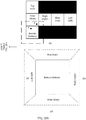
- the extended region is specifically obtained by extending or filling the face around the face. As shown in (a) in FIG.
- the current pixel P is located on a bottom face, and then an extended region needs to be constructed for a bottom face in the reference image.
- a range of the extended region is shown by a dashed-line region outside the bottom face in (b) in FIG. 20B .
- a polyhedron that is corresponding to the reference image and is shown in (c) in FIG. 20A may be constructed by using the bottom face in the reference image as the bottom. If the polyhedron is spread, locations that are in the extended region and are respectively of a rear face, a front face, a left face, a right face, and the like of the polyhedron are shown in (d) in FIG. 20B .
- the motion-compensated prediction method in the embodiment of this application shown in FIG. 5 may be used: First, a spherical reference location is determined based on a location of the first pixel and a location of a sphere center of a sphere corresponding to the reference image; then, a polyhedral reference location is determined; and finally, a location of a second pixel in the reference image is determined, and a pixel value of the first pixel is determined based on the second pixel (a pixel value of the second pixel may be directly determined as the pixel value of the first pixel, or a specific operation may be performed on the second pixel or a pixel around the second pixel, and a pixel value obtained through the operation is used as the pixel value of the first pixel).
- the first pixel is similar to the initial reference pixel in the motion-compensated prediction method in the embodiment of this application shown in FIG. 5
- the second pixel is similar to the target reference pixel in the motion-compensated prediction method in the embodiment of this application shown in FIG. 5 .
- a reference pixel of the current pixel is determined, and whether the reference pixel is located on a face corresponding to the face on which the current pixel is located is determined based on the face on which the current pixel is located and a location of the reference pixel. If the reference pixel is located on a face that is at a same location as the current pixel, a pixel value at the location of the reference pixel may be directly used as a prediction value of a pixel value of the current pixel. Otherwise, the following operation needs to be performed: A corresponding location of the reference pixel in the extended region is first determined based on a location offset of the reference pixel relative to the current pixel. As shown in (b) in FIG.
- a reference pixel T is not located on a face that is at a same location as the current pixel P. In this case, based on the location offset of the reference pixel relative to the current pixel, it can be learned that the reference pixel T should be located in a region that is corresponding to the rear face and that is in the extended region. If the extended region is placed based on an actual relative spatial location, as shown in (d) in FIG. 20B , the location of the reference pixel in the extended region is determined based on the relative location offset. Otherwise, the location of the reference pixel in the extended region needs to be determined based on a specific method for placing the extended region.
- the pixel value at the location is used as the prediction value of the pixel value of the current pixel.
- a pixel in the foregoing extended region may be an integer pixel, or may be a fractional pixel. If the pixel is a fractional pixel, a specific pixel value may be 1/2 precision, 1/4 precision, 1/8 precision, or the like.
- an interpolation operation needs to be performed on the reference pixel.
- a DCT interpolation method a bilinear interpolation method, or another interpolation method may be used.
- a difference between the method shown in FIG. 19 and the method shown in FIG. 5 is as follows:
- a pixel value of a pixel in the extended region is calculated in advance, so that when prediction is performed for the current pixel, it can be more convenient to directly find the target reference pixel in the extended region, and a calculation process of determining the location of the target reference pixel based on the location of the initial reference pixel is omitted.
- the method shown in FIG. 5 when the pixel value of the current pixel is predicted, the location of the target reference pixel is determined based on the location of the initial reference pixel, and therefore an additional calculation process exists compared with the method shown in FIG. 19 .
- other steps of the method shown in FIG. 19 are basically the same as other steps of the method shown in FIG. 5 . For brevity, repeated descriptions are appropriately omitted.
- FIG. 21 is a schematic flowchart of a motion-compensated prediction method according to an embodiment of this application. The method shown in FIG. 21 includes the following steps:
- the initial reference pixel When the initial reference pixel is located outside a second sub-image that is in the reference image and that is at a location corresponding to the first sub-image, determine, based on the location of the initial reference pixel, a location that is of a target reference pixel of the current pixel and that is on a surface of a polyhedron corresponding to the reference image, where a connection line between the location, that is of the target reference pixel and that is on the surface of the polyhedron, and a location that is of the initial reference pixel and that is on a first plane passes through a body center of the polyhedron, and the first plane is a plane on which a face that is of the polyhedron and that is corresponding to the second sub-image is located.
- the target reference pixel that can really play a reference role is found based on the location of the initial reference pixel, and then the pixel value of the current pixel is predicted based on the target reference pixel, thereby improving accuracy of motion-compensated prediction.
- a difference between the motion-compensated prediction method shown in FIG. 5 and the motion-compensated prediction method shown in FIG. 21 is as follows: In FIG. 5 , the spherical reference location is determined based on the location of the initial reference pixel and the location of the sphere center of the sphere; then, the polyhedral reference location is determined based on the spherical reference location; finally, the location of the target reference pixel in the reference image is determined based on the polyhedral reference location. In FIG. 5 , the spherical reference location is determined based on the location of the initial reference pixel and the location of the sphere center of the sphere; then, the polyhedral reference location is determined based on the spherical reference location; finally, the location of the target reference pixel in the reference image is determined based on the polyhedral reference location. In FIG. 5 , the spherical reference location is determined based on the location of the initial reference pixel and the location of the sphere center of the sphere
- the location that is of the target reference pixel and that is on the surface of the polyhedron corresponding to the reference image is first determined based on the location of the initial reference pixel, and then the location of the target reference pixel in the reference image is determined based on the location that is of the target reference pixel and that is on the surface of the polyhedron.
- the method shown in FIG. 5 is to determine the location of the target reference pixel in the reference image by performing three steps
- the method shown in FIG. 21 is to determine the location of the target reference pixel in the reference image by performing two steps.
- the determining, based on the location of the initial reference pixel, a location that is of a target reference pixel of the current pixel and that is on a surface of a polyhedron corresponding to the reference image includes: determining, based on the location of the initial reference pixel and layout information of the reference image, the location that is of the initial reference pixel and that is on the first plane; and determining, based on the layout information of the reference image and the location that is of the initial reference pixel and that is on the first plane, the location that is of the target reference pixel and that is on the surface of the polyhedron.
- the determining a location of the target reference pixel in the reference image based on the location that is of the target reference pixel and that is on the surface of the polyhedron includes: determining the location of the target reference pixel in the reference image based on the location of the initial reference pixel and the layout information of the reference image, where the location that is of the target reference pixel and that is on the surface of the polyhedron is at a point at which the surface of the polyhedron is intersected with a connection line between the initial reference pixel and the body center of the polyhedron.
- the motion-compensated prediction method in this embodiment of this application is applicable to two-dimensional images in various polyhedral formats.
- the motion-compensated prediction method in this embodiment of this application is also applicable to a case in which a face in the two-dimensional image in the polyhedral format is rotated, a face arrangement order is changed, and a spatial layout format of faces is changed.
- the pixel value at the location of the target reference pixel may be calculated when the pixel value of the current pixel is predicted.
- the pixel value of the target reference pixel of the to-be-processed pixel may be calculated in advance. In this way, when the to-be-processed pixel is processed, the pixel value of the target reference pixel of the to-be-processed pixel can be directly obtained, thereby saving image processing time.
- the foregoing describes in detail the motion-compensated prediction method in this embodiment of this application by using a two-dimensional image in a 4 ⁇ 3 format.
- the motion-compensated prediction method in this embodiment of this application is also applicable to two-dimensional images in other polyhedral formats.
- the motion-compensated prediction method in this embodiment of this application is also applicable to a case in which faces in the two-dimensional image are partially or all rotated, different face arrangement orders, different face arrangement methods, and the like.
- a pixel value of a reference pixel in the reference image may be directly used as the prediction value of the pixel value of the current pixel; or a weighted value of a pixel value of a reference pixel and a pixel value of a pixel around the reference pixel or a pixel value obtained by performing another operation on the pixel value of the reference pixel and the pixel value of the pixel around the reference pixel may be used as the prediction value of the pixel value of the current pixel.
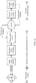
- the motion-compensated prediction method in this embodiment of this application may be applied to an architecture shown in FIG. 22 , and may be specifically applied to a process of encoding and decoding a two-dimensional panoramic image.
- an existing VR video image collection device is usually a circular or spherical multi-camera array. Each camera may collect images at different angles to obtain a multi-angle-of-view video image of a current scene.
- a VR video processing device performs image splicing on the multi-angle-of-view image to obtain a three-dimensional spherical panorama, and then maps the three-dimensional spherical panorama to obtain a two-dimensional panorama image, to facilitate input of subsequent operations such as processing, compression, transmission, and storage.
- the VR video processing device stores, in a transmission server, a result obtained through processing.
- a VR head-mounted display device may obtain, through a network or the like, the image processing result stored in the transmission server, and may display the three-dimensional spherical panoramic image after performing a corresponding operation such as decoding.
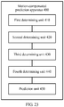
- FIG. 23 is a schematic block diagram of a motion-compensated prediction apparatus 400 according to an embodiment of this application.
- the motion-compensated prediction apparatus 400 includes:
- the target reference pixel that can really play a reference role is found based on the location of the initial reference pixel, and then the pixel value of the current pixel is predicted based on the target reference pixel, thereby improving accuracy of motion estimation prediction.
- the second determining unit 420 is specifically configured to:
- the motion-compensated prediction apparatus 400 further includes: a judging unit 460, configured to determine, based on layout information of the reference image and the location of the initial reference pixel, whether the initial reference pixel is located outside the second sub-image in the reference image.
- a judging unit 460 configured to determine, based on layout information of the reference image and the location of the initial reference pixel, whether the initial reference pixel is located outside the second sub-image in the reference image.
- the fourth determining unit 440 is specifically configured to: determine the location of the target reference pixel in the reference image based on the polyhedral reference location and layout information of the polyhedron.
- the layout information includes at least one of face quantity information of the polyhedron, sub-image arrangement manner information of the reference image, sub-image arrangement order information of the reference image, and sub-image rotation information of the reference image.
- the prediction unit 450 is specifically configured to: determine the pixel value of the target reference pixel as the prediction value of the pixel value of the current pixel.
- the prediction unit 450 is specifically configured to:
- the prediction unit 450 is specifically configured to:
- FIG. 24 is a schematic block diagram of a motion-compensated prediction apparatus according to an embodiment of this application.
- the motion-compensated prediction apparatus 500 includes:
- the target reference pixel that can really play a reference role is found in the extended region directly based on the current pixel and motion information of the current pixel, and then the pixel value of the current pixel is predicted based on the target reference pixel, so that the target reference pixel can be quickly found, and accuracy of motion estimation prediction can be improved.
- the motion-compensated prediction apparatus further includes:
- the third determining unit 540 is specifically configured to:
- the motion-compensated prediction apparatus further includes: a judging unit 570, configured to determine, based on layout information of the reference image and the location of the initial reference pixel, whether the initial reference pixel is located outside the second sub-image in the reference image.
- a judging unit 570 configured to determine, based on layout information of the reference image and the location of the initial reference pixel, whether the initial reference pixel is located outside the second sub-image in the reference image.
- FIG. 25 is a schematic block diagram of a motion-compensated prediction apparatus according to an embodiment of this application.
- the motion-compensated prediction apparatus 600 includes:
- the target reference pixel that can really play a reference role is found based on the location of the initial reference pixel, and then the pixel value of the current pixel is predicted based on the target reference pixel, thereby improving accuracy of motion estimation prediction.
- the second determining unit 620 is specifically configured to:
- the third determining unit is specifically configured to: determine the location of the target reference pixel in the reference image based on the location of the initial reference pixel and the layout information of the reference image, where the location that is of the target reference pixel and that is on the surface of the polyhedron is at a point at which the surface of the polyhedron is intersected with a connection line between the initial reference pixel and the body center of the polyhedron.
- the motion-compensated prediction method in the embodiments of this application may be considered as an intermediate process or step in an encoding or decoding process, and a panoramic video encoder or a panoramic video decoder may implement the motion-compensated prediction method in the embodiments of this application.
- the current image Before a current image is encoded, the current image is usually divided into several equal-sized blocks, and then an encoding operation is performed on each block.
- layout information of the current image is usually transmitted to a decoder side as header information.
- the header information is pilot information, so that after receiving an encoded bitstream, the decoder first decodes the header information, and then decodes a subsequent bitstream based on the header information. It is assumed that during encoding, the current image is divided into a plurality of image blocks for sequential encoding, and decoding is sequentially performed in a same order. For a current block, if an inter coding manner is used for the current block, to obtain reconstructed information of the current block, a reconstructed value of a pixel value of a pixel in the current block needs to be obtained.
- the process mainly includes steps such as intra prediction (Intra Prediction), inter prediction (Inter Prediction), transform (Transform), quantization (Quantization), and entropy encoding (Entropy encoding).
- intra prediction and inter prediction may be performed after the image is divided into image blocks; then transform and quantization are performed after a residual is obtained; and finally, entropy encoding is performed and a bitstream is output.
- the image block herein is an M ⁇ N array including pixels (where both M and N are integers greater than 0, and M may be equal to N, or may not be equal to N), and a pixel value at a location of each pixel is known.
- Intra prediction is to predict a pixel value of a pixel in a current block by using a pixel value of a pixel in a reconstructed region in a current image.
- Inter prediction is to search a reconstructed image for a matching reference block for a current coding block in a current image; use a pixel value of a pixel in the reference block as prediction information or a prediction value (the following no longer distinguishes information and a value) of a pixel value of a pixel in the current coding block (this process is referred to as motion estimation (Motion estimation, ME)); and transmit, to the decoder side, motion vector (motion vector, MV) information (namely, a location offset of a location of the reference block relative to a location of the current block) of the current block pointing to the reference block, indication information of an image in which the reference block is located, and the like.
- motion vector motion vector
- a plurality of reference blocks in a reference image need to be selected for the current block, and a reference block or reference blocks that is/are finally used to perform prediction for the current block may be determined by using a rate-distortion optimization (Rate-distortion optimization, RDO) method or another method.
- RDO rate-distortion optimization
- residual information may be obtained by subtracting the corresponding prediction information (namely, the pixel value of the corresponding pixel in the corresponding reference block) from the pixel value of the pixel in the current coding block.
- the residual information is transformed by using a method such as discrete cosine transform (Discrete Cosine Transformation, DCT), and a bitstream is finally obtained through quantization and entropy encoding.
- DCT discrete cosine transform
- Decoding is equivalent to an inverse process of encoding.
- decoding first, residual information is obtained through entropy decoding, dequantization, and inverse transform, and whether intra prediction or inter prediction is used for a current block is determined based on a decoded bitstream. If intra coding is used, prediction information is constructed by using the used intra prediction method and a pixel value of a pixel that is in a reconstructed region and that is around a current to-be-processed pixel.
- motion information needs to be parsed out; a reference block is determined from a reconstructed image based on the motion information obtained through parsing, and a pixel value of a pixel in the block is used as prediction information (this process is also referred to as motion compensation); and finally, reconstructed information may be obtained by adding the prediction information and the residual information.
- FIG. 26 is a schematic flowchart of a decoding process of a panoramic video decoder. The method specifically includes the following steps.
- the decoder may decode a motion information bitstream, and determine the motion information of the current block based on a parsing result.
- the motion information of the current block may further be determined by decoding indication information of prediction motion information and difference information between the prediction motion information and the motion information, that is, the motion information of the current block may be determined without directly parsing an encoded bitstream of the motion information.
- the decoder side may construct a motion information set (for example, the motion information set includes motion information of a reconstructed block adjacent to the current block in terms of time or space, and a method for constructing the set is jointly agreed on between an encoder side and the decoder side).
- the decoder side may parse the indication information of the prediction motion information, then determine the prediction motion information from the set, and obtain the motion information of the current block based on the prediction motion information and the difference information between the prediction motion information and the motion information.
- the decoder side may further use, as the motion information of the current block, the prediction motion information determined based on the indication information of the prediction motion information.
- a specific method to be used is agreed on between the encoder side and the decoder side, or the encoder side transmits information about a used manner to the decoder side, and the decoder side determines, based on the received manner information, a manner used to determine the motion information of the current block.
- step 710 if unidirectional reference is used, one piece of motion information needs to be parsed out. If bidirectional reference is used, two pieces of motion information need to be parsed out. A specific quantity of pieces of motion information that need to be parsed out is jointly agreed on between the encoder side and the decoder side, or the encoder side transmits information related to a used piece quantity to the decoder side, and the decoder side determines the used piece quantity based on a parsing result.
- the decoder may determine, based on the motion information of the current block, a reference image of the current image in which the current block is located, and determine a location of a reference block in the reference image.
- determining the prediction value of the pixel value of the pixel in the current block is determining a prediction value of a pixel value of each pixel in the current block, and the prediction value of the pixel value of the pixel may be specifically determined based on the motion-compensated prediction method in the embodiments of this application.
- a prediction block of the current block may be obtained based on the prediction value of the pixel value of each pixel, and the prediction block includes the prediction value of the pixel value of each pixel in the current block.
- step 720 if unidirectional reference is used, a location of only one reference block in a reference image in which the reference block is located needs to be determined. For one pixel in the current block, a location of only one reference pixel needs to be determined, and then the prediction value of the pixel value of the pixel in the current block may be determined based on the motion-compensated prediction method in the embodiments of this application.
- locations that are of two reference blocks of the current block and are in respective reference images of the two reference blocks need to be determined. For one pixel in the current block, locations of two reference pixels in the two reference blocks need to be separately determined.
- two prediction values of the pixel value of the pixel in the current block may be determined based on the motion-compensated prediction method in the embodiments of this application.
- weighted processing or another operation is performed on the two prediction values to obtain the prediction value of the pixel value of the pixel in the current block.
- a specific operation manner is jointly agreed on between the encoder side and the decoder side, or the encoder side transmits a used method to the decoder side, and the decoder side determines the used method based on a parsing result.
- another operation may be performed on the prediction value first, and a prediction value obtained by performing the operation is used as a final prediction value of the pixel value of the current pixel.
- a prediction value obtained after smooth filtering is performed on the obtained prediction value may be used as the final prediction value of the pixel value of the current pixel.
- whether to perform another operation and a used manner are jointly agreed on between the encoder side and the decoder side, or the encoder side transmits a used method to the decoder side, and the decoder side determines the used method based on a parsing result.
- bidirectional prediction may further be performed on the pixel value of the current pixel, that is, prediction may be performed for the current pixel twice, and then weighted processing is performed on two obtained prediction values to obtain the prediction value of the pixel value of the current pixel.
- the decoder decodes an encoded bitstream of the residual information of the pixel value of the pixel in the current block, and obtains the residual information of the pixel value of the pixel in the current block by using a dequantization method and an inverse transform method. To be specific, the decoder decodes an encoded bitstream of a residual block of the current block, and then obtains the residual block of the current block by using the dequantization method and the inverse transform method.
- step 730 to determine the residual information of the pixel value of the pixel in the current block, only the inverse transform method or only the dequantization method may be used.
- a specific method to be used is jointly agreed on between the encoder side and the decoder side, or the encoder side transmits a used method to the decoder side, and the decoder side determines the used method based on a parsing result.
- a reconstructed value of the pixel value of each pixel in the current block may be obtained based on the pixel value that is of the pixel in the current block and that is obtained in step 720 and the residual information that is of the pixel value of the pixel in the current block and that is obtained in step 730.
- the prediction block of the current block may be obtained based on step 720, and then a reconstructed block of the current block may be obtained by adding the prediction block and the residual block obtained in step 730.
- the reconstructed block includes the reconstructed value of the pixel value of each pixel in the current block.
- step 740 to obtain the reconstructed value of the pixel value of the pixel in the current block, after the prediction information and the residual information are added, some other operations may also need to be performed, such as de-blocking filtering. Specifically, whether other operations are required and which of the other operations is performed are jointly agreed on between the encoder side and the decoder side, or the encoder side transmits a used method to the decoder side, and the decoder side determines the used method based on a parsing result.
- the decoding process of the panoramic video decoder with reference to FIG. 26 .
- the decoding process is usually performed on an encoded bitstream obtained through encoding.
- FIG. 27 the following describes in detail an encoding process by using a panoramic video encoder as an example.
- layout information of a spherical image may be determined after the spherical image is collected or generated. Therefore, before the encoder encodes a panoramic video, the encoder has learned of the layout information of the spherical image.
- the layout information of the spherical image is usually transmitted as header information.
- the header information is pilot information.
- a decoder first decodes the header information, and then may decode a subsequent bitstream after obtaining the layout information of the spherical image based on the header information.
- FIG. 27 is a schematic flowchart of an encoding process of a panoramic video encoder. The method specifically includes the following steps.
- the encoder first determines the motion information of the current block, and then encodes the motion information. Specifically, the encoder selects a reference image from a reconstructed image for a current image; searches a specified region in the reference image for a matching block for the current block; uses the matching block as a reference block of the current block; uses, as motion information, the reference image used in this process and motion vector information indicating a location offset of the reference block relative to the current block; and encodes the motion information.
- a plurality of blocks may be selected for the current block first, and which block is finally selected as the reference block may be determined according to a rate-distortion optimization criterion. For example, a quantity of bits of motion information that need to be encoded when a candidate reference block is used as the matching block and a distortion value existing when a pixel value of a pixel in the current block is predicted by using a pixel value of a pixel in the current candidate reference block are determined, and a cost of the candidate reference block is determined by using a Lagrange optimization method. Then, a candidate reference block with a minimum cost is selected as the matching block.
- a plurality of reference images exist the foregoing operation needs to be performed on each image.
- the motion information may not be directly encoded. Instead, indication information of prediction motion information or difference information between prediction motion information and the motion information is encoded.
- the encoder side may construct a motion information set (for example, the motion information set includes motion information of a reconstructed block adjacent to the current block in terms of time or space, and a method for constructing the set is jointly agreed on between the encoder side and a decoder side).
- the encoder side may select one piece of motion information from the set as the prediction motion information, then obtain the difference information between the motion information of the current block and the prediction motion information, and encode the indication information of the prediction motion information and the difference information.
- the encoder may encode only the indication information of the prediction motion information, so that the decoder side can determine motion information from the constructed motion information set based on the indication information, and use the motion information as the motion information of the current block.
- a specific method to be used is agreed on between the encoder side and the decoder side, or may be selected by using a rate-distortion optimization method, and the selected method is transmitted to the decoder side.
- step 810 if unidirectional reference is used, only one piece of motion information needs to be encoded. If bidirectional reference is used, two pieces of motion information need to be encoded. A specific quantity of pieces of motion information that need to be encoded is jointly agreed on between the encoder side and the decoder side, or may be determined by using the rate-distortion optimization method, and the encoder side transmits corresponding information to the decoder side.
- a location of one reference block in a reference image in which the reference block is located needs to be determined. For one current pixel in the current block, a location of one reference pixel needs to be determined, and then a prediction value of the pixel value of the pixel in the current block is determined based on the motion-compensated prediction method in the embodiments of this application. If bidirectional reference is used, locations that are of two reference blocks of the current block and are in respective reference images of the two reference blocks need to be determined. To be specific, for one pixel in the current block, locations of two reference pixels in the two reference blocks need to be separately determined.
- two prediction values of the pixel value of the pixel in the current block may be determined based on the motion-compensated prediction method in the embodiments of this application. Then, weighted processing or another operation is performed on the two prediction values to obtain a prediction value of the pixel value of the pixel in the current block.
- a specific operation manner is jointly agreed on between the encoder side and the decoder side, or the encoder side transmits a used method to the decoder side, and the decoder side determines the used method based on a parsing result.
- the encoder may determine, based on the motion information of the current block, a reference image of a current image in which the current block is located, and determine a location of a reference block in the reference image.
- determining the prediction value of the pixel value of the pixel in the current block is determining a prediction value of a pixel value of each pixel in the current block, and the prediction value of the pixel value of the pixel may be specifically determined based on the motion-compensated prediction method in the embodiments of this application.
- another operation may be performed on the prediction value first, and a prediction value obtained by performing the operation is used as a final prediction value of the pixel value of the current pixel.
- a prediction value obtained after smooth filtering is performed on the obtained prediction value may be used as the final prediction value of the pixel value of the current pixel.
- whether to perform another operation and a used manner are jointly agreed on between the encoder side and the decoder side, or the encoder side transmits a used method to the decoder side, and the decoder side determines the used method based on a parsing result.
- bidirectional prediction may further be performed on the pixel value of the current pixel, that is, prediction may be performed for the current pixel twice, and then weighted processing is performed on two obtained prediction values to obtain the prediction value of the pixel value of the current pixel.
- the encoder subtracts the prediction value from the pixel value of the pixel in the current block, to obtain the residual information of the pixel value of the pixel in the current block; then processes the residual information of the pixel value of the pixel in the current block based on a transform method and a quantization method; and encodes a result obtained through processing.
- the residual information of the pixel value of the pixel in the current block is encoded, only the transform method or only the quantization method may be used.
- a specific method to be used is jointly agreed on between the encoder side and the decoder side, or is determined by the encoder side by using the rate-distortion optimization method, and transmits information to the decoder side.
- FIG. 28 is a schematic block diagram of an image encoder 900 according to an embodiment of this application.
- the image encoder 900 includes a prediction module 910, a transform and quantization module 920, an entropy encoding module 930, a reconstruction module 940, and a filtering module 950.
- a specific function of each module is as follows:
- the prediction module 910 is configured to generate prediction data.
- the prediction module 910 may generate one or more prediction units (PU) of each CU that cannot be partitioned. Each PU of the CU may be associated with different pixel blocks in a pixel block of the CU.
- the prediction module 910 may generate a predictive pixel block for each PU of the CU.
- the prediction module 910 may generate the predictive pixel block of the PU through intra prediction or inter prediction. If the prediction module 910 generates the predictive pixel block of the PU through intra prediction, the prediction module 910 may generate the predictive pixel block of the PU based on a pixel in a decoded picture associated with the PU.
- the prediction module 910 may generate the predictive pixel block of the PU based on a pixel in one or more decoded pictures different from a picture associated with the PU.
- the prediction module 910 may generate a residual pixel block of the CU based on the predictive pixel block of the PU of the CU.
- the residual pixel block of the CU may indicate a difference between a sample value in the predictive pixel block of the PU of the CU and a corresponding sample value in an reference pixel block of the CU.
- the transform and quantization module 920 is configured to process residual data obtained through prediction.
- the image encoder 900 may perform recursive quadtree partitioning on the residual pixel block of the CU, to partition the residual pixel block of the CU into one or more smaller residual pixel blocks associated with a transform unit (TU) of the CU. Because each pixel in the pixel block associated with the TU is corresponding to one luma sample and two chroma samples, each TU may be associated with one luma residual sample block and two chroma residual sample blocks.
- the image encoder 900 may apply one or more times of transform to the residual sample block associated with the TU to generate a coefficient block (namely, a block of coefficients).
- the transform may be DCT transform or a variant thereof.
- a DCT transform matrix is used, and two-dimensional transform is calculated by using one-dimensional transform in a horizontal direction and a vertical direction, to obtain the coefficient block.
- the image encoder 900 may perform a quantization operation on each coefficient in the coefficient block. Quantization usually means a process in which the coefficient is quantized to reduce an amount of data used to represent the coefficient to provide further compression.
- the image encoder 900 may generate a set of syntax elements that represent the quantized coefficients in the coefficient block.
- the image encoder 900 may apply an entropy encoding operation (such as a context-adaptive binary arithmetic coding (CABAC) operation) to some or all of the foregoing syntax elements by using the entropy encoding module 930.
- CABAC context-adaptive binary arithmetic coding
- the entropy encoding module 930 may binarize the syntax elements to form a binary sequence including one or more bits (referred to as "binary digit").
- the entropy encoding module 930 may encode a part of the binary digits through regular (regular) encoding, and may encode another part of the binary digits through bypass (bypass) encoding.
- the image encoder 900 may apply, by using the reconstruction module 940, dequantization and inverse transform to the coefficient block obtained through transform, to reconstruct the residual sample block from the coefficient block obtained through transform.
- the image encoder 900 may add the reconstructed residual sample block and a corresponding sample block of one or more predictive sample blocks, to generate a reconstructed sample block.
- the image encoder 900 may reconstruct a pixel block associated with the TU by reconstructing a sample block of each color component. A pixel block of each TU of the CU is reconstructed in this manner, until reconstruction of the entire pixel block of the CU is completed.
- the image encoder 900 After the image encoder 900 reconstructs the pixel block of the CU, the image encoder 900 performs a de-blocking filtering operation by using the filtering module 950, to reduce a blocking effect of a pixel block associated with the CU. After performing the de-blocking filtering operation, the image encoder 900 may modify a reconstructed pixel block of a CTB of a picture by using a sample adaptive offset (SAO) process. After performing these operations, the image encoder 900 may store the reconstructed pixel block of the CU in a decoded picture buffer, to generate a predictive pixel block of another CU.
- SAO sample adaptive offset
- the described functions may be implemented by hardware, software, firmware, or any combination thereof. If the functions are implemented by software, the functions may be stored in a computer readable medium as one or more instructions or code lines or sent by a computer readable medium, and are executed by a hardware-based processing unit.
- the computer readable medium may include a computer readable storage medium (which is corresponding to a tangible medium such as a data storage medium) or a communications medium.
- the communications medium includes, for example, any medium that facilitates transmission of a computer program from a place to another place according to a communication protocol.
- the computer readable medium may be generally corresponding to: (1) a non-transitory tangible computer readable storage medium, or (2) a communications medium such as a signal or a carrier.
- the data storage medium may be accessed by one or more computers or one or more processors to retrieve an instruction, code, and/or a data structure, to implement any available medium in technologies described in this application.
- a computer program product may include a computer readable medium.
- some computer readable storage media may include a RAM, a ROM, an EEPROM, a CD-ROM or another optical disc storage, a magnetic disk storage or another magnetic storage apparatus, a flash memory, or any other medium that can be used to store required program code in a form of an instruction or a data structure and can be accessed by a computer.
- any connection may be appropriately referred to as a computer readable medium.
- an instruction is sent from a website, a server, or another remote source by using a coaxial cable, an optical cable, a twisted pair, a digital subscriber line (DSL), or a wireless technology (such as infrared, radio, or microwave)
- the coaxial cable, the optical cable, the twisted pair, the DSL, or the wireless technology is included in a definition of a medium.
- the computer readable storage medium and the data storage medium do not include a connection, a carrier, a signal, or another transitory medium, but are non-transitory tangible storage media.
- a disk and an optical disc used in this specification include a compact disc (CD), a laser disc, an optical disc, a digital versatile disc (DVD), a floppy disk, and a Blu-ray disc.
- the disk usually copies data by a magnetic means, and the optical disc optically copies data by a laser means.
- processors such as one or more digital signal processors (DSP), a general microprocessor, an application-specific integrated circuit (ASIC), a field programmable gate array (FPGA), or another equivalent integrated circuit or discrete logic circuit. Therefore, the term "processor” used in this specification may mean the foregoing structure or any other structure applicable to implementation of the technologies described in this specification.
- DSP digital signal processors
- ASIC application-specific integrated circuit
- FPGA field programmable gate array
- processors used in this specification may mean the foregoing structure or any other structure applicable to implementation of the technologies described in this specification.
- the functions described in this specification may be provided in a dedicated hardware and/or software module configured for encoding and decoding, or may be incorporated into a combined codec.
- the technologies may be totally implemented in one or more circuits or logic elements.
- the technologies in this application may be widely implemented by a plurality of apparatuses or devices.
- the apparatus or the device includes a radio handset, an integrated circuit (IC), or an IC set (such as a chip set).
- IC integrated circuit
- IC set such as a chip set
- various components, modules, and units are described to emphasize functions of an apparatus configured to implement the disclosed technologies, but the functions do not need to be implemented by different hardware units.
- various units may be combined into a hardware unit of the codec, or may be provided by a set of interoperable hardware units (including one or more processors described above) and appropriate software and/or firmware.
- an implementation or “one implementation” mentioned in the whole specification means that particular features, structures, or characteristics related to the implementation are included in at least one implementation of this application. Therefore, “in an implementation” or “in one implementation” appearing throughout the specification does not mean a same implementation. In addition, these particular features, structures, or characteristics may be combined in one or more implementations in any appropriate manner.
- sequence numbers of the foregoing processes do not mean execution sequences in various implementations of this application.
- the execution sequences of the processes should be determined according to functions and internal logic of the processes, and should not be construed as any limitation on the implementation processes of the implementations of this application.
- system and “network” in this specification may be used interchangeably in this specification.
- network in this specification describes only an association relationship for describing associated objects and represents that three relationships may exist.
- a and/or B may represent the following three cases: Only A exists, both A and B exist, and only B exists.
- character "/" in this specification usually indicates an "or" relationship between the associated objects.
- B corresponding to A indicates that B is associated with A, and B may be determined based on A.
- determining A based on B does not mean that B is determined based on A only, that is, B may also be determined based on A and/or other information.
- the disclosed system, apparatus, and method may be implemented in other manners.
- the described apparatus embodiment is merely an example.
- the unit division is merely logical function division and may be other division in actual implementation.
- a plurality of units or components may be combined or integrated into another system, or some features may be ignored or not performed.
- the displayed or discussed mutual couplings or direct couplings or communication connections may be implemented by using some interfaces.
- the indirect couplings or communication connections between the apparatuses or units may be implemented in electronic, mechanical, or other forms.
- the units described as separate parts may or may not be physically separate, and parts displayed as units may or may not be physical units, may be located in one position, or may be distributed on a plurality of network units. Some or all of the units may be selected based on actual requirements to achieve the objectives of the solutions of the embodiments.
- function units in the embodiments of this application may be integrated into one processing unit, or each of the units may exist alone physically, or two or more units may be integrated into one unit.
- the functions When the functions are implemented in a form of a software function unit and sold or used as an independent product, the functions may be stored in a computer readable storage medium. Based on such an understanding, the technical solutions of this application essentially, or the part contributing to the prior art, or some of the technical solutions may be implemented in a form of a software product.
- the computer software product is stored in a storage medium, and includes several instructions for instructing a computer device (which may be a personal computer, a server, a network device, or the like) to perform all or some of the steps of the methods described in the embodiments of this application.
- the foregoing storage medium includes any medium that can store program code, such as a USB flash drive, a removable hard disk, a read-only memory (Read-Only Memory, ROM), a random access memory (Random Access Memory, RAM), a magnetic disk, or an optical disc.
- program code such as a USB flash drive, a removable hard disk, a read-only memory (Read-Only Memory, ROM), a random access memory (Random Access Memory, RAM), a magnetic disk, or an optical disc.
Landscapes
- Engineering & Computer Science (AREA)
- Multimedia (AREA)
- Signal Processing (AREA)
- Compression Or Coding Systems Of Tv Signals (AREA)
- Image Analysis (AREA)
Claims (12)
- Verfahren für eine bewegungskompensierte Vorhersage, das zum Decodieren/Codieren von zweidimensionalen Panoramabildern verwendet wird, das Folgendes umfasst:Bestimmen einer Position eines anfänglichen Referenzpixels eines aktuellen Pixels in einem Referenzbild basierend auf Bewegungsinformationen, die von einem Bitstrom erhalten werden, wobei sich das aktuelle Pixel in einem ersten Teilbild in einem aktuellen Bild befindet;wenn sich das anfängliche Referenzpixel außerhalb eines zweiten Teilbildes befindet, das in dem Referenzbild gelegen ist und das an einer Position gelegen ist, die dem ersten Teilbild entspricht, Bestimmen, basierend auf der Position des anfänglichen Referenzpixels und einer Position eines Kugelmittelpunkts einer Kugel, die dem Referenzbild entspricht, einer kugelförmigen Referenzposition, die einem Zielreferenzpixel des aktuellen Pixels entspricht und die auf einer Oberfläche der Kugel gelegen ist;Bestimmen, basierend auf der kugelförmigen Referenzposition, einer polyedrischen Referenzposition, die dem Zielreferenzpixel entspricht und die auf einer Oberfläche eines Polyeders gelegen ist, das dem Referenzbild entspricht, wobei die Kugel das Polyeder intern tangiert, und wobei eine Verbindungslinie zwischen der polyedrischen Referenzposition und dem Kugelmittelpunkt durch die kugelförmige Referenzposition verläuft;Bestimmen einer Position des Zielreferenzpixels in dem Referenzbild basierend auf der polyedrischen Referenzposition; undBestimmen eines Vorhersagewerts eines Pixelwerts des aktuellen Pixels basierend auf einem Pixelwert des Zielreferenzpixels und/oder einem Pixelwert eines benachbarten Pixels des Zielreferenzpixels innerhalb des Referenzbildes, wobei der Vorhersagewert des Pixelwerts des aktuellen Pixels verwendet wird, um einen rekonstruierten Wert des Pixelwerts des aktuellen Pixels zusammen mit einem Restwert des aktuellen Pixels zu erhalten;wobei das Bestimmen einer Position des Zielreferenzpixels in dem Referenzbild basierend auf der polyedrischen Referenzposition Folgendes umfasst:
Bestimmen der Position des Zielreferenzpixels in dem Referenzbild basierend auf der polyedrischen Referenzposition und den Layoutinformationen des Polyeders durch Zuordnen der polyedrischen Referenzposition an die Position des Zielreferenzpixels des Referenzbildes gemäß einer Zuordnungsbeziehung, die durch die Layoutinformationen des Polyeders definiert ist, wobei die Layoutinformationen Flächenmengeninformationen des Polyeders, Teilbildanordnungsweiseinformationen des Referenzbildes, Teilbildanordnungsreihenfolgeinformationen des Referenzbildes und/oder Teilbildrotationsinformationen des Referenzbildes umfassen. - Verfahren nach Anspruch 1, wobei das Bestimmen, basierend auf der Position des anfänglichen Referenzpixels und einer Position eines Kugelmittelpunkts einer Kugel, die dem Referenzbild entspricht, einer kugelförmigen Referenzposition, die einem Zielreferenzpixel des aktuellen Pixels entspricht und das auf einer Oberfläche der Kugel gelegen ist, Folgendes umfasst:Bestimmen, basierend auf der Position des anfänglichen Referenzpixels und einem Versatzwert der Position des anfänglichen Referenzpixels relativ zu dem zweiten Teilbild, einer ersten Position, die von dem anfänglichen Referenzpixel ist und die auf einer Ebene gelegen ist, auf der sich eine erste Fläche des Polyeders befindet, wobei die erste Fläche eine Fläche ist, die dem zweiten Teilbild entspricht und die von dem Polyeder ist; undBestimmen, basierend auf der ersten Position und der Position des Kugelmittelpunkts der Kugel, der kugelförmigen Referenzposition, die dem Zielreferenzpixel entspricht und die auf der Oberfläche der Kugel gelegen ist, wobei eine Verbindungslinie zwischen der ersten Position und der Position des Kugelmittelpunkts durch die kugelförmige Referenzposition verläuft.
- Verfahren nach Anspruch 1 oder 2, wobei das Verfahren ferner Folgendes umfasst:
Bestimmen, basierend auf Layoutinformationen des Referenzbilds und der Position des anfänglichen Referenzpixels, ob sich das anfängliche Referenzpixel außerhalb des zweiten Teilbildes in dem Referenzbild befindet. - Verfahren nach einem der Ansprüche 1 bis 3, wobei das Bestimmen eines Vorhersagewerts eines Pixelwerts des aktuellen Pixels basierend auf einem Pixelwert des Zielreferenzpixels und/oder einem Pixelwert eines benachbarten Pixels des Zielreferenzpixels Folgendes umfasst:
Bestimmen des Pixelwerts des Zielreferenzpixels als den Vorhersagewert des Pixelwerts des aktuellen Pixels. - Verfahren nach einem der Ansprüche 1 bis 3, wobei das Bestimmen eines Vorhersagewerts eines Pixelwerts des aktuellen Pixels basierend auf einem Pixelwert des Zielreferenzpixels und/oder einem Pixelwert eines benachbarten Pixels des Zielreferenzpixels Folgendes umfasst:Durchführen eines gewichteten Verarbeitens an dem Pixelwert des Zielreferenzpixels und dem Pixelwert des benachbarten Pixels des Zielreferenzpixels; undBestimmen, als den Vorhersagewert des Pixelwerts des aktuellen Pixels, eines Pixelwerts, der an der Position des Zielreferenzpixels gelegen ist und der durch das gewichtete Verarbeiten erhalten wird.
- Verfahren nach einem der Ansprüche 1 bis 3, wobei das Bestimmen eines Vorhersagewerts eines Pixelwerts des aktuellen Pixels basierend auf einem Pixelwert des Zielreferenzpixels und/oder einem Pixelwert eines benachbarten Pixels des Zielreferenzpixels Folgendes umfasst:Durchführen einer Interpolationsoperation an der Position des Zielreferenzpixels basierend auf dem Pixelwert des benachbarten Pixels des Zielreferenzpixels; undBestimmen, als den Vorhersagewert des Pixelwerts des aktuellen Pixels, eines Pixelwerts, der durch die Interpolationsoperation erhalten wird.
- Vorrichtung für die bewegungskompensierte Vorhersage, die zum Decodieren/Codieren von zweidimensionalen Panoramabildern verwendet wird, die Folgendes umfasst:eine erste Bestimmungseinheit, die konfiguriert ist, um eine Position eines anfänglichen Referenzpixels eines aktuellen Pixels in einem Referenzbild basierend auf Bewegungsinformationen, die von einem Bitstrom erhalten wird, zu bestimmen, wobei sich das aktuelle Pixel in einem ersten Teilbild in einem aktuellen Bild befindet;eine zweite Bestimmungseinheit, die für Folgendes konfiguriert ist: wenn sich das anfängliche Referenzpixel außerhalb eines zweiten Teilbildes befindet, das in dem Referenzbild gelegen ist und das an einer Position gelegen ist, die dem ersten Teilbild entspricht, Bestimmen, basierend auf der Position des anfänglichen Referenzpixels und einer Position eines Kugelmittelpunkts einer Kugel, die dem Referenzbild entspricht, einer kugelförmigen Referenzposition, die einem Zielreferenzpixel des aktuellen Pixels entspricht und die auf einer Oberfläche der Kugel gelegen ist;eine dritte Bestimmungseinheit, die konfiguriert ist, um, basierend auf der kugelförmigen Referenzposition, eine polyedrische Referenzposition, die dem Zielreferenzpixel entspricht und die auf einer Oberfläche eines Polyeders gelegen ist, das dem Referenzbild entspricht, zu bestimmen, wobei die Kugel das Polyeder intern tangiert, und wobei eine Verbindungslinie zwischen der polyedrischen Referenzposition und dem Kugelmittelpunkt durch die kugelförmige Referenzposition verläuft;eine vierte Bestimmungseinheit, die konfiguriert ist, um eine Position des Zielreferenzpixels in dem Referenzbild basierend auf der polyedrischen Referenzposition durch Zuordnen der polyedrischen Referenzposition an die Position des Zielreferenzpixels des Referenzbildes gemäß einer Zuordnungsbeziehung, die durch die Layoutinformationen des Polyeders definiert ist, zu bestimmen; undeine Vorhersageeinheit, die konfiguriert ist, um einen Vorhersagewert eines Pixelwerts des aktuellen Pixels basierend auf einem Pixelwert des Zielreferenzpixels und/oder einem Pixelwert eines benachbarten Pixels des Zielreferenzpixels innerhalb des Referenzbildes zu bestimmen, wobei der Vorhersagewert des Pixelwerts des aktuellen Pixels verwendet wird, um einen rekonstruierten Wert des Pixelwerts des aktuellen Pixels zusammen mit einem Restwert des aktuellen Pixels zu erhalten;wobei die vierte Bestimmungseinheit speziell für Folgendes konfiguriert ist:Bestimmen der Position des Zielreferenzpixels in dem Referenzbild basierend auf der polyedrischen Referenzposition und Layoutinformationen des Polyeders;wobei die Layoutinformationen Flächenmengeninformationen des Polyeders, Teilbildanordnungsweiseinformationen des Referenzbildes, Teilbildanordnungsreihenfolgeinformationen des Referenzbildes und/oder Teilbildrotationsinformationen des Referenzbildes umfassen.
- Vorrichtung für die bewegungskompensierte Vorhersage nach Anspruch 7, wobei die zweite Bestimmungseinheit speziell für Folgendes konfiguriert ist:Bestimmen, basierend auf der Position des anfänglichen Referenzpixels und einem Versatzwert der Position des anfänglichen Referenzpixels relativ zu dem zweiten Teilbild, einer ersten Position, die von dem anfänglichen Referenzpixel ist und die auf einer Ebene gelegen ist, auf der sich eine erste Fläche des Polyeders befindet, wobei die erste Fläche eine Fläche ist, die dem zweiten Teilbild entspricht und die von dem Polyeder ist; undBestimmen, basierend auf der ersten Position und der Position des Kugelmittelpunkts der Kugel, der kugelförmigen Referenzposition, die dem Zielreferenzpixel entspricht und die auf der Oberfläche der Kugel gelegen ist, wobei eine Verbindungslinie zwischen der ersten Position und der Position des Kugelmittelpunkts durch die kugelförmige Referenzposition verläuft.
- Vorrichtung für die bewegungskompensierte Vorhersage nach Anspruch 7 oder 8, wobei die Vorrichtung für die bewegungskompensierte Vorhersage ferner Folgendes umfasst:
eine Beurteilungseinheit, die konfiguriert ist um, basierend auf Layoutinformationen des Referenzbildes und der Position des anfänglichen Referenzpixels, zu bestimmen, ob sich das anfängliche Referenzpixel außerhalb des zweiten Teilbildes in dem Referenzbild befindet. - Vorrichtung für die bewegungskompensierte Vorhersage nach einem der Ansprüche 7 bis 9, wobei die Vorhersageinheit speziell für Folgendes konfiguriert ist:
Bestimmen des Pixelwerts des Zielreferenzpixels als den Vorhersagewert des Pixelwerts des aktuellen Pixels. - Vorrichtung für die bewegungskompensierte Vorhersage nach einem der Ansprüche 7 bis 9, wobei die Vorhersageinheit speziell für Folgendes konfiguriert ist:Durchführen eines gewichteten Verarbeitens an dem Pixelwert des Zielreferenzpixels und dem Pixelwert des benachbarten Pixels des Zielreferenzpixels; undBestimmen, als den Vorhersagewert des Pixelwerts des aktuellen Pixels, eines Pixelwerts, der an der Position des Zielreferenzpixels gelegen ist und der durch das gewichtete Verarbeiten erhalten wird.
- Vorrichtung für die bewegungskompensierte Vorhersage nach einem der Ansprüche 7 bis 9, wobei die Vorhersageinheit speziell für Folgendes konfiguriert ist:Durchführen einer Interpolationsoperation an der Position des Zielreferenzpixels basierend auf dem Pixelwert des benachbarten Pixels des Zielreferenzpixels; undBestimmen, als den Vorhersagewert des Pixelwerts des aktuellen Pixels, eines Pixelwerts, der durch die Interpolationsoperation erhalten wird.
Applications Claiming Priority (3)
| Application Number | Priority Date | Filing Date | Title |
|---|---|---|---|
| CN201610876864 | 2016-09-30 | ||
| CN201610896430.5A CN107888928B (zh) | 2016-09-30 | 2016-10-13 | 运动补偿预测方法和设备 |
| PCT/CN2017/104030 WO2018059500A1 (zh) | 2016-09-30 | 2017-09-28 | 运动补偿预测方法和设备 |
Publications (3)
| Publication Number | Publication Date |
|---|---|
| EP3515076A1 EP3515076A1 (de) | 2019-07-24 |
| EP3515076A4 EP3515076A4 (de) | 2019-07-24 |
| EP3515076B1 true EP3515076B1 (de) | 2021-11-10 |
Family
ID=61770276
Family Applications (1)
| Application Number | Title | Priority Date | Filing Date |
|---|---|---|---|
| EP17854950.7A Active EP3515076B1 (de) | 2016-09-30 | 2017-09-28 | Verfahren und vorrichtung zur bewegungskompensationsvorhersage |
Country Status (3)
| Country | Link |
|---|---|
| US (1) | US10779000B2 (de) |
| EP (1) | EP3515076B1 (de) |
| CN (1) | CN107888928B (de) |
Families Citing this family (11)
| Publication number | Priority date | Publication date | Assignee | Title |
|---|---|---|---|---|
| KR102598082B1 (ko) * | 2016-10-28 | 2023-11-03 | 삼성전자주식회사 | 영상 표시 장치, 모바일 장치 및 그 동작방법 |
| US10999602B2 (en) * | 2016-12-23 | 2021-05-04 | Apple Inc. | Sphere projected motion estimation/compensation and mode decision |
| US11259046B2 (en) * | 2017-02-15 | 2022-02-22 | Apple Inc. | Processing of equirectangular object data to compensate for distortion by spherical projections |
| US10924747B2 (en) | 2017-02-27 | 2021-02-16 | Apple Inc. | Video coding techniques for multi-view video |
| US11093752B2 (en) | 2017-06-02 | 2021-08-17 | Apple Inc. | Object tracking in multi-view video |
| US10754242B2 (en) | 2017-06-30 | 2020-08-25 | Apple Inc. | Adaptive resolution and projection format in multi-direction video |
| KR102427648B1 (ko) * | 2017-11-03 | 2022-08-01 | 삼성전자주식회사 | 결함 검사 방법 및 결함 검사 장치 |
| US10715832B2 (en) * | 2018-03-16 | 2020-07-14 | Mediatek Inc. | Method and apparatus of block partition for VR360 video coding |
| US11323748B2 (en) * | 2018-12-19 | 2022-05-03 | Qualcomm Incorporated | Tree-based transform unit (TU) partition for video coding |
| WO2021127118A1 (en) * | 2019-12-17 | 2021-06-24 | Alibaba Group Holding Limited | Methods for performing wrap-around motion compensation |
| CN118823685B (zh) * | 2024-09-18 | 2024-12-17 | 厦门众联世纪股份有限公司 | 一种基于混合专家网络的人群定位方法、系统和存储介质 |
Family Cites Families (8)
| Publication number | Priority date | Publication date | Assignee | Title |
|---|---|---|---|---|
| CN101521823B (zh) | 2009-03-27 | 2010-12-01 | 北京航空航天大学 | 空间相关的全景数据压缩方法 |
| JP2013046270A (ja) * | 2011-08-25 | 2013-03-04 | Olympus Corp | 画像貼り合せ装置、撮影装置、画像貼り合せ方法、および画像処理プログラム |
| US9986154B2 (en) * | 2014-05-21 | 2018-05-29 | Here Global B.V. | Developing a panoramic image |
| CN106664403B (zh) * | 2014-10-20 | 2020-10-16 | 谷歌有限责任公司 | 连续预测域 |
| CN105681805B (zh) * | 2016-01-19 | 2019-05-21 | 北京大学深圳研究生院 | 视频编码、解码方法及其帧间预测方法和装置 |
| US20170214937A1 (en) * | 2016-01-22 | 2017-07-27 | Mediatek Inc. | Apparatus of Inter Prediction for Spherical Images and Cubic Images |
| CN105959702B (zh) * | 2016-05-30 | 2019-03-22 | 北京奇艺世纪科技有限公司 | 一种球面视频编码方法和装置 |
| WO2018041005A1 (zh) * | 2016-08-30 | 2018-03-08 | 华为技术有限公司 | 运动补偿预测方法和设备 |
-
2016
- 2016-10-13 CN CN201610896430.5A patent/CN107888928B/zh active Active
-
2017
- 2017-09-28 EP EP17854950.7A patent/EP3515076B1/de active Active
-
2019
- 2019-04-01 US US16/371,486 patent/US10779000B2/en active Active
Non-Patent Citations (1)
| Title |
|---|
| None * |
Also Published As
| Publication number | Publication date |
|---|---|
| EP3515076A1 (de) | 2019-07-24 |
| CN107888928A (zh) | 2018-04-06 |
| EP3515076A4 (de) | 2019-07-24 |
| US10779000B2 (en) | 2020-09-15 |
| CN107888928B (zh) | 2020-02-14 |
| US20190230377A1 (en) | 2019-07-25 |
Similar Documents
| Publication | Publication Date | Title |
|---|---|---|
| EP3515076B1 (de) | Verfahren und vorrichtung zur bewegungskompensationsvorhersage | |
| US11863732B1 (en) | Image data encoding/decoding method and apparatus | |
| JP7557024B2 (ja) | 画像予測方法および関連装置 | |
| US20250227375A1 (en) | Method and apparatus for reconstructing 360-degree image according to projection format | |
| US11128874B2 (en) | Motion compensating prediction method and device | |
| US11831915B1 (en) | Method and apparatus of encoding/decoding image data based on tree structure-based block division | |
| US10911767B2 (en) | Motion compensating prediction method and apparatus | |
| US20210150665A1 (en) | Image processing method and device | |
| WO2018041005A1 (zh) | 运动补偿预测方法和设备 | |
| CN112313958A (zh) | 用于编码和解码视频信号的装置和方法 | |
| US12621422B2 (en) | Image data encoding/decoding method and apparatus | |
| US20260129161A1 (en) | Image data encoding/decoding method and apparatus | |
| US20260129162A1 (en) | Image data encoding/decoding method and apparatus | |
| US20260129167A1 (en) | Image data encoding/decoding method and apparatus | |
| WO2018059500A1 (zh) | 运动补偿预测方法和设备 |
Legal Events
| Date | Code | Title | Description |
|---|---|---|---|
| STAA | Information on the status of an ep patent application or granted ep patent |
Free format text: STATUS: THE INTERNATIONAL PUBLICATION HAS BEEN MADE |
|
| PUAI | Public reference made under article 153(3) epc to a published international application that has entered the european phase |
Free format text: ORIGINAL CODE: 0009012 |
|
| STAA | Information on the status of an ep patent application or granted ep patent |
Free format text: STATUS: REQUEST FOR EXAMINATION WAS MADE |
|
| 17P | Request for examination filed |
Effective date: 20190415 |
|
| A4 | Supplementary search report drawn up and despatched |
Effective date: 20190606 |
|
| AK | Designated contracting states |
Kind code of ref document: A1 Designated state(s): AL AT BE BG CH CY CZ DE DK EE ES FI FR GB GR HR HU IE IS IT LI LT LU LV MC MK MT NL NO PL PT RO RS SE SI SK SM TR |
|
| AX | Request for extension of the european patent |
Extension state: BA ME |
|
| DAV | Request for validation of the european patent (deleted) | ||
| DAX | Request for extension of the european patent (deleted) | ||
| STAA | Information on the status of an ep patent application or granted ep patent |
Free format text: STATUS: EXAMINATION IS IN PROGRESS |
|
| 17Q | First examination report despatched |
Effective date: 20200318 |
|
| REG | Reference to a national code |
Ref country code: DE Ref legal event code: R079 Ref document number: 602017049252 Country of ref document: DE Free format text: PREVIOUS MAIN CLASS: H04N0019520000 Ipc: H04N0019105000 |
|
| RIC1 | Information provided on ipc code assigned before grant |
Ipc: H04N 19/105 20140101AFI20210412BHEP Ipc: H04N 19/176 20140101ALI20210412BHEP Ipc: H04N 19/182 20140101ALI20210412BHEP Ipc: H04N 19/52 20140101ALI20210412BHEP Ipc: H04N 19/547 20140101ALI20210412BHEP Ipc: H04N 19/597 20140101ALI20210412BHEP Ipc: H04N 19/85 20140101ALI20210412BHEP |
|
| GRAP | Despatch of communication of intention to grant a patent |
Free format text: ORIGINAL CODE: EPIDOSNIGR1 |
|
| STAA | Information on the status of an ep patent application or granted ep patent |
Free format text: STATUS: GRANT OF PATENT IS INTENDED |
|
| RAP3 | Party data changed (applicant data changed or rights of an application transferred) |
Owner name: HUAWEI TECHNOLOGIES CO., LTD. |
|
| INTG | Intention to grant announced |
Effective date: 20210609 |
|
| GRAS | Grant fee paid |
Free format text: ORIGINAL CODE: EPIDOSNIGR3 |
|
| GRAA | (expected) grant |
Free format text: ORIGINAL CODE: 0009210 |
|
| STAA | Information on the status of an ep patent application or granted ep patent |
Free format text: STATUS: THE PATENT HAS BEEN GRANTED |
|
| AK | Designated contracting states |
Kind code of ref document: B1 Designated state(s): AL AT BE BG CH CY CZ DE DK EE ES FI FR GB GR HR HU IE IS IT LI LT LU LV MC MK MT NL NO PL PT RO RS SE SI SK SM TR |
|
| REG | Reference to a national code |
Ref country code: GB Ref legal event code: FG4D |
|
| REG | Reference to a national code |
Ref country code: AT Ref legal event code: REF Ref document number: 1447162 Country of ref document: AT Kind code of ref document: T Effective date: 20211115 Ref country code: CH Ref legal event code: EP |
|
| REG | Reference to a national code |
Ref country code: DE Ref legal event code: R096 Ref document number: 602017049252 Country of ref document: DE |
|
| REG | Reference to a national code |
Ref country code: IE Ref legal event code: FG4D |
|
| REG | Reference to a national code |
Ref country code: LT Ref legal event code: MG9D |
|
| REG | Reference to a national code |
Ref country code: NL Ref legal event code: MP Effective date: 20211110 |
|
| REG | Reference to a national code |
Ref country code: AT Ref legal event code: MK05 Ref document number: 1447162 Country of ref document: AT Kind code of ref document: T Effective date: 20211110 |
|
| PG25 | Lapsed in a contracting state [announced via postgrant information from national office to epo] |
Ref country code: RS Free format text: LAPSE BECAUSE OF FAILURE TO SUBMIT A TRANSLATION OF THE DESCRIPTION OR TO PAY THE FEE WITHIN THE PRESCRIBED TIME-LIMIT Effective date: 20211110 Ref country code: LT Free format text: LAPSE BECAUSE OF FAILURE TO SUBMIT A TRANSLATION OF THE DESCRIPTION OR TO PAY THE FEE WITHIN THE PRESCRIBED TIME-LIMIT Effective date: 20211110 Ref country code: FI Free format text: LAPSE BECAUSE OF FAILURE TO SUBMIT A TRANSLATION OF THE DESCRIPTION OR TO PAY THE FEE WITHIN THE PRESCRIBED TIME-LIMIT Effective date: 20211110 Ref country code: BG Free format text: LAPSE BECAUSE OF FAILURE TO SUBMIT A TRANSLATION OF THE DESCRIPTION OR TO PAY THE FEE WITHIN THE PRESCRIBED TIME-LIMIT Effective date: 20220210 Ref country code: AT Free format text: LAPSE BECAUSE OF FAILURE TO SUBMIT A TRANSLATION OF THE DESCRIPTION OR TO PAY THE FEE WITHIN THE PRESCRIBED TIME-LIMIT Effective date: 20211110 |
|
| PG25 | Lapsed in a contracting state [announced via postgrant information from national office to epo] |
Ref country code: IS Free format text: LAPSE BECAUSE OF FAILURE TO SUBMIT A TRANSLATION OF THE DESCRIPTION OR TO PAY THE FEE WITHIN THE PRESCRIBED TIME-LIMIT Effective date: 20220310 Ref country code: SE Free format text: LAPSE BECAUSE OF FAILURE TO SUBMIT A TRANSLATION OF THE DESCRIPTION OR TO PAY THE FEE WITHIN THE PRESCRIBED TIME-LIMIT Effective date: 20211110 Ref country code: PT Free format text: LAPSE BECAUSE OF FAILURE TO SUBMIT A TRANSLATION OF THE DESCRIPTION OR TO PAY THE FEE WITHIN THE PRESCRIBED TIME-LIMIT Effective date: 20220310 Ref country code: PL Free format text: LAPSE BECAUSE OF FAILURE TO SUBMIT A TRANSLATION OF THE DESCRIPTION OR TO PAY THE FEE WITHIN THE PRESCRIBED TIME-LIMIT Effective date: 20211110 Ref country code: NO Free format text: LAPSE BECAUSE OF FAILURE TO SUBMIT A TRANSLATION OF THE DESCRIPTION OR TO PAY THE FEE WITHIN THE PRESCRIBED TIME-LIMIT Effective date: 20220210 Ref country code: NL Free format text: LAPSE BECAUSE OF FAILURE TO SUBMIT A TRANSLATION OF THE DESCRIPTION OR TO PAY THE FEE WITHIN THE PRESCRIBED TIME-LIMIT Effective date: 20211110 Ref country code: LV Free format text: LAPSE BECAUSE OF FAILURE TO SUBMIT A TRANSLATION OF THE DESCRIPTION OR TO PAY THE FEE WITHIN THE PRESCRIBED TIME-LIMIT Effective date: 20211110 Ref country code: HR Free format text: LAPSE BECAUSE OF FAILURE TO SUBMIT A TRANSLATION OF THE DESCRIPTION OR TO PAY THE FEE WITHIN THE PRESCRIBED TIME-LIMIT Effective date: 20211110 Ref country code: GR Free format text: LAPSE BECAUSE OF FAILURE TO SUBMIT A TRANSLATION OF THE DESCRIPTION OR TO PAY THE FEE WITHIN THE PRESCRIBED TIME-LIMIT Effective date: 20220211 Ref country code: ES Free format text: LAPSE BECAUSE OF FAILURE TO SUBMIT A TRANSLATION OF THE DESCRIPTION OR TO PAY THE FEE WITHIN THE PRESCRIBED TIME-LIMIT Effective date: 20211110 |
|
| PG25 | Lapsed in a contracting state [announced via postgrant information from national office to epo] |
Ref country code: SM Free format text: LAPSE BECAUSE OF FAILURE TO SUBMIT A TRANSLATION OF THE DESCRIPTION OR TO PAY THE FEE WITHIN THE PRESCRIBED TIME-LIMIT Effective date: 20211110 Ref country code: SK Free format text: LAPSE BECAUSE OF FAILURE TO SUBMIT A TRANSLATION OF THE DESCRIPTION OR TO PAY THE FEE WITHIN THE PRESCRIBED TIME-LIMIT Effective date: 20211110 Ref country code: RO Free format text: LAPSE BECAUSE OF FAILURE TO SUBMIT A TRANSLATION OF THE DESCRIPTION OR TO PAY THE FEE WITHIN THE PRESCRIBED TIME-LIMIT Effective date: 20211110 Ref country code: EE Free format text: LAPSE BECAUSE OF FAILURE TO SUBMIT A TRANSLATION OF THE DESCRIPTION OR TO PAY THE FEE WITHIN THE PRESCRIBED TIME-LIMIT Effective date: 20211110 Ref country code: DK Free format text: LAPSE BECAUSE OF FAILURE TO SUBMIT A TRANSLATION OF THE DESCRIPTION OR TO PAY THE FEE WITHIN THE PRESCRIBED TIME-LIMIT Effective date: 20211110 Ref country code: CZ Free format text: LAPSE BECAUSE OF FAILURE TO SUBMIT A TRANSLATION OF THE DESCRIPTION OR TO PAY THE FEE WITHIN THE PRESCRIBED TIME-LIMIT Effective date: 20211110 |
|
| REG | Reference to a national code |
Ref country code: DE Ref legal event code: R097 Ref document number: 602017049252 Country of ref document: DE |
|
| PLBE | No opposition filed within time limit |
Free format text: ORIGINAL CODE: 0009261 |
|
| STAA | Information on the status of an ep patent application or granted ep patent |
Free format text: STATUS: NO OPPOSITION FILED WITHIN TIME LIMIT |
|
| 26N | No opposition filed |
Effective date: 20220811 |
|
| PG25 | Lapsed in a contracting state [announced via postgrant information from national office to epo] |
Ref country code: AL Free format text: LAPSE BECAUSE OF FAILURE TO SUBMIT A TRANSLATION OF THE DESCRIPTION OR TO PAY THE FEE WITHIN THE PRESCRIBED TIME-LIMIT Effective date: 20211110 |
|
| PG25 | Lapsed in a contracting state [announced via postgrant information from national office to epo] |
Ref country code: SI Free format text: LAPSE BECAUSE OF FAILURE TO SUBMIT A TRANSLATION OF THE DESCRIPTION OR TO PAY THE FEE WITHIN THE PRESCRIBED TIME-LIMIT Effective date: 20211110 |
|
| PG25 | Lapsed in a contracting state [announced via postgrant information from national office to epo] |
Ref country code: MC Free format text: LAPSE BECAUSE OF FAILURE TO SUBMIT A TRANSLATION OF THE DESCRIPTION OR TO PAY THE FEE WITHIN THE PRESCRIBED TIME-LIMIT Effective date: 20211110 |
|
| REG | Reference to a national code |
Ref country code: CH Ref legal event code: PL |
|
| REG | Reference to a national code |
Ref country code: BE Ref legal event code: MM Effective date: 20220930 |
|
| PG25 | Lapsed in a contracting state [announced via postgrant information from national office to epo] |
Ref country code: IT Free format text: LAPSE BECAUSE OF FAILURE TO SUBMIT A TRANSLATION OF THE DESCRIPTION OR TO PAY THE FEE WITHIN THE PRESCRIBED TIME-LIMIT Effective date: 20211110 |
|
| P01 | Opt-out of the competence of the unified patent court (upc) registered |
Effective date: 20230524 |
|
| PG25 | Lapsed in a contracting state [announced via postgrant information from national office to epo] |
Ref country code: LU Free format text: LAPSE BECAUSE OF NON-PAYMENT OF DUE FEES Effective date: 20220928 |
|
| PG25 | Lapsed in a contracting state [announced via postgrant information from national office to epo] |
Ref country code: LI Free format text: LAPSE BECAUSE OF NON-PAYMENT OF DUE FEES Effective date: 20220930 Ref country code: IE Free format text: LAPSE BECAUSE OF NON-PAYMENT OF DUE FEES Effective date: 20220928 Ref country code: CH Free format text: LAPSE BECAUSE OF NON-PAYMENT OF DUE FEES Effective date: 20220930 |
|
| PG25 | Lapsed in a contracting state [announced via postgrant information from national office to epo] |
Ref country code: BE Free format text: LAPSE BECAUSE OF NON-PAYMENT OF DUE FEES Effective date: 20220930 |
|
| PG25 | Lapsed in a contracting state [announced via postgrant information from national office to epo] |
Ref country code: HU Free format text: LAPSE BECAUSE OF FAILURE TO SUBMIT A TRANSLATION OF THE DESCRIPTION OR TO PAY THE FEE WITHIN THE PRESCRIBED TIME-LIMIT; INVALID AB INITIO Effective date: 20170928 |
|
| PG25 | Lapsed in a contracting state [announced via postgrant information from national office to epo] |
Ref country code: CY Free format text: LAPSE BECAUSE OF FAILURE TO SUBMIT A TRANSLATION OF THE DESCRIPTION OR TO PAY THE FEE WITHIN THE PRESCRIBED TIME-LIMIT Effective date: 20211110 |
|
| PG25 | Lapsed in a contracting state [announced via postgrant information from national office to epo] |
Ref country code: MK Free format text: LAPSE BECAUSE OF FAILURE TO SUBMIT A TRANSLATION OF THE DESCRIPTION OR TO PAY THE FEE WITHIN THE PRESCRIBED TIME-LIMIT Effective date: 20211110 |
|
| PG25 | Lapsed in a contracting state [announced via postgrant information from national office to epo] |
Ref country code: TR Free format text: LAPSE BECAUSE OF FAILURE TO SUBMIT A TRANSLATION OF THE DESCRIPTION OR TO PAY THE FEE WITHIN THE PRESCRIBED TIME-LIMIT Effective date: 20211110 |
|
| PG25 | Lapsed in a contracting state [announced via postgrant information from national office to epo] |
Ref country code: MT Free format text: LAPSE BECAUSE OF FAILURE TO SUBMIT A TRANSLATION OF THE DESCRIPTION OR TO PAY THE FEE WITHIN THE PRESCRIBED TIME-LIMIT Effective date: 20211110 |
|
| PGFP | Annual fee paid to national office [announced via postgrant information from national office to epo] |
Ref country code: DE Payment date: 20250805 Year of fee payment: 9 |
|
| PGFP | Annual fee paid to national office [announced via postgrant information from national office to epo] |
Ref country code: GB Payment date: 20250807 Year of fee payment: 9 |
|
| PGFP | Annual fee paid to national office [announced via postgrant information from national office to epo] |
Ref country code: FR Payment date: 20250808 Year of fee payment: 9 |