EP3515372B1 - Dispositif d'accouplement de prothèse conçu pour une prothèse, et prothèse équipée de ce dispositif d'accouplement de prothèse - Google Patents
Dispositif d'accouplement de prothèse conçu pour une prothèse, et prothèse équipée de ce dispositif d'accouplement de prothèse Download PDFInfo
- Publication number
- EP3515372B1 EP3515372B1 EP17772669.2A EP17772669A EP3515372B1 EP 3515372 B1 EP3515372 B1 EP 3515372B1 EP 17772669 A EP17772669 A EP 17772669A EP 3515372 B1 EP3515372 B1 EP 3515372B1
- Authority
- EP
- European Patent Office
- Prior art keywords
- prosthesis
- locking
- coupling
- socket
- coupler
- Prior art date
- Legal status (The legal status is an assumption and is not a legal conclusion. Google has not performed a legal analysis and makes no representation as to the accuracy of the status listed.)
- Not-in-force
Links
- 230000008878 coupling Effects 0.000 title claims description 118
- 238000010168 coupling process Methods 0.000 title claims description 118
- 238000005859 coupling reaction Methods 0.000 title claims description 118
- 230000006835 compression Effects 0.000 claims description 14
- 238000007906 compression Methods 0.000 claims description 14
- 230000007704 transition Effects 0.000 claims description 5
- 238000005096 rolling process Methods 0.000 claims description 2
- 230000006378 damage Effects 0.000 description 5
- 239000000463 material Substances 0.000 description 3
- 230000008439 repair process Effects 0.000 description 3
- XECAHXYUAAWDEL-UHFFFAOYSA-N acrylonitrile butadiene styrene Chemical compound C=CC=C.C=CC#N.C=CC1=CC=CC=C1 XECAHXYUAAWDEL-UHFFFAOYSA-N 0.000 description 2
- 229920000122 acrylonitrile butadiene styrene Polymers 0.000 description 2
- 239000004676 acrylonitrile butadiene styrene Substances 0.000 description 2
- 230000009471 action Effects 0.000 description 2
- 239000000853 adhesive Substances 0.000 description 2
- 230000001070 adhesive effect Effects 0.000 description 2
- 238000010276 construction Methods 0.000 description 2
- 230000003247 decreasing effect Effects 0.000 description 2
- 229920000747 poly(lactic acid) Polymers 0.000 description 2
- 208000027418 Wounds and injury Diseases 0.000 description 1
- 238000005452 bending Methods 0.000 description 1
- 230000008901 benefit Effects 0.000 description 1
- 230000008859 change Effects 0.000 description 1
- 238000006073 displacement reaction Methods 0.000 description 1
- 208000014674 injury Diseases 0.000 description 1
- 238000003780 insertion Methods 0.000 description 1
- 230000037431 insertion Effects 0.000 description 1
- 230000003993 interaction Effects 0.000 description 1
- 230000014759 maintenance of location Effects 0.000 description 1
- 230000007246 mechanism Effects 0.000 description 1
- 230000002093 peripheral effect Effects 0.000 description 1
- 239000007787 solid Substances 0.000 description 1
- 229920001169 thermoplastic Polymers 0.000 description 1
- 239000004416 thermosoftening plastic Substances 0.000 description 1
- 230000003313 weakening effect Effects 0.000 description 1
Images


Classifications
-
- A—HUMAN NECESSITIES
- A61—MEDICAL OR VETERINARY SCIENCE; HYGIENE
- A61F—FILTERS IMPLANTABLE INTO BLOOD VESSELS; PROSTHESES; DEVICES PROVIDING PATENCY TO, OR PREVENTING COLLAPSING OF, TUBULAR STRUCTURES OF THE BODY, e.g. STENTS; ORTHOPAEDIC, NURSING OR CONTRACEPTIVE DEVICES; FOMENTATION; TREATMENT OR PROTECTION OF EYES OR EARS; BANDAGES, DRESSINGS OR ABSORBENT PADS; FIRST-AID KITS
- A61F2/00—Filters implantable into blood vessels; Prostheses, i.e. artificial substitutes or replacements for parts of the body; Appliances for connecting them with the body; Devices providing patency to, or preventing collapsing of, tubular structures of the body, e.g. stents
- A61F2/50—Prostheses not implantable in the body
- A61F2/78—Means for protecting prostheses or for attaching them to the body, e.g. bandages, harnesses, straps, or stockings for the limb stump
-
- A—HUMAN NECESSITIES
- A61—MEDICAL OR VETERINARY SCIENCE; HYGIENE
- A61F—FILTERS IMPLANTABLE INTO BLOOD VESSELS; PROSTHESES; DEVICES PROVIDING PATENCY TO, OR PREVENTING COLLAPSING OF, TUBULAR STRUCTURES OF THE BODY, e.g. STENTS; ORTHOPAEDIC, NURSING OR CONTRACEPTIVE DEVICES; FOMENTATION; TREATMENT OR PROTECTION OF EYES OR EARS; BANDAGES, DRESSINGS OR ABSORBENT PADS; FIRST-AID KITS
- A61F2/00—Filters implantable into blood vessels; Prostheses, i.e. artificial substitutes or replacements for parts of the body; Appliances for connecting them with the body; Devices providing patency to, or preventing collapsing of, tubular structures of the body, e.g. stents
- A61F2/50—Prostheses not implantable in the body
- A61F2002/5081—Additional features
- A61F2002/5083—Additional features modular
Definitions
- the present invention describes a prosthesis coupling for a prosthesis, as well as a prosthesis with the prosthesis coupling according to the preamble of the first claim and a prosthesis with such a prosthesis coupling.
- prosthesis coupling or a prosthetic adapter which can be attached to an extremity stump and to a prosthesis module, here a prosthetic foot.
- the prosthesis coupling comprises a first component for attaching the prosthesis coupling to a prosthesis socket designed to receive an extremity stump, and a second component for attaching the prosthesis coupling to the prosthesis module.
- Axial mobility and possible rotation of the prosthesis shaft relative to the prosthesis module is prevented in a technically complicated manner on both the first and the second component by means of a large number of screws.
- a prosthesis coupling can be screwed to the prosthesis socket on one side. Furthermore, the prosthesis coupling can be actuated by pressing a button on the prosthesis socket and thereby the prosthesis module, here in the form of a hand prosthesis, from the prosthesis socket or from the prosthesis coupling section fixed to the prosthesis socket on the other side of this prosthesis socket releasable, while both prosthesis coupling sections and thus the prosthesis socket can be connected to the prosthesis module by means of a latching mechanism.
- the "Michelangelo Hand” is extremely robust and inevitably heavy. Since this prosthesis should be able to perform a wide variety of movements and can also be operated externally, this massive design is necessary.
- the prosthesis shaft is solid and, on the other hand, the prosthesis module is complex.
- the prosthesis coupling sections are also designed to be robust and technically complex, which means that not every prosthesis wearer is able to connect and disconnect the prosthesis module.
- the known prosthesis coupling sections are so heavy that the wearing comfort is reduced.
- a prosthesis coupling according to the preamble of claim 1 is from the patent GB 2 278 281 A known. There is a continuing need to improve the handling for the prosthesis wearer even further and to ensure simplified coupling and uncoupling. Especially when a prosthesis wearer has several prosthesis modules and wants to change them more often.
- the present invention has therefore set itself the task of providing a prosthesis coupling for a prosthesis, as well as a prosthesis with the prosthesis coupling, which allows simplified handling by a prosthesis wearer.
- a prosthesis module is to be fastened to a prosthesis socket by means of a prosthesis coupling in such a way that the prosthesis module is prevented from falling down during coupling and uncoupling with one hand.
- the prosthesis coupling comprises a first coupling section with two closure elements movably held in a closure base and a second coupling section with a connecting component, wherein the connecting component can be received and held in position in a corresponding receiving area between the two closing elements, and wherein the closing elements are by means of one, of one
- the open position can be moved into a closed position, and the locking ring can be locked in its mobility in a closed position so that a detachable connection can be established between the prosthesis module and the prosthesis socket by means of the prosthesis coupling.
- the prosthesis module After receiving the connection component fixed to it, the prosthesis module is already held provisionally in position in the receiving area between the closure elements before a secure connection is established between the prosthesis module and the prosthesis socket by means of the locking ring. This means that the prosthesis coupling can be operated with one hand without risk.
- the currently used prosthesis module can easily be replaced by a prosthesis module adapted to a different application by the user himself without the help of another person, and this replacement can also be carried out easily by children.
- the connecting component can be selected in the form of a hexagonal element or in any other polygonal shape, whereby the Number of possible radial positions of the prosthesis module can be varied as desired.
- the connecting component preferably comprises a disk element, preferably aligned essentially concentrically to the hexagonal element, the hexagonal element being molded onto the disk element and a predetermined breaking point being formed between the hexagonal element and the disk element.
- this is passed on by the prosthesis coupling and, in addition to the prosthesis module or the prosthesis coupling, can even damage the prosthesis socket and / or injure the limb stump of the user.
- the prosthesis module is advantageously decoupled at a desired point in the event of a hard impact, thereby protecting the user's extremity stump from injury or the prosthesis socket or the prosthesis module from damage.
- this connecting component is a simple and inexpensive component that can be replaced by the prosthesis wearer himself without any special specialist knowledge, thereby eliminating repair costs or repair times.
- a predetermined breaking point is understood to mean, in particular, a construction element provided by constructive or mechanical or physical measures or designs, here the connecting component, with this construction element failing in a targeted and predictable manner in the event of damage or overload, thereby preventing the possible damage in the overall system keep it small.
- An overload case can occur, for example, due to tension, torsion and / or bending.
- the prosthesis coupling comprises a detent disc element that can be attached between the prosthesis module and the disc element, the detent disc element being mountable for a corresponding detent of the disc element facing the detent disc element, so that the hexagonal element formed on the disc element can also be adjusted radially with respect to the prosthesis module.
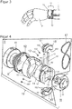
- Fig. 1 shows a first preferred embodiment of a prosthesis coupling 10, comprising a first coupling section I and a second coupling section II, which can be releasably connected to and uncoupled from one another.
- the first coupling section I is attached here to a prosthesis socket 1, the prosthesis socket 1 being fixed to an extremity stump E of the user or prosthesis wearer.
- An arm or leg stump can be understood as the extremity stump E, and a hand or foot prosthesis can be understood as the prosthesis module P.
- the second coupling section II is attached to a prosthesis module P.
- the prosthesis module P and prosthesis socket 1 are detachably connected to one another by the interaction of the first and second coupling sections I, II.
- the prosthesis coupling 10 or the first and second coupling sections I, II comprise a fastening ring 11, a compression spring element 12, a locking ring 13, a locking base 14 and a connecting component V compatible with the locking base 14.
- the first coupling section I comprises the fastening ring 11, the compression spring element 12, the locking ring 13 and the locking base 14. Movably held locking elements 15 ', 15 "are arranged in the locking base 14, which are also part of the first coupling section I.
- the fastening ring 11 of the prosthesis coupling 10 is received here in a receiving area of the prosthesis socket 1 and fastened or fixed therein by suitable means. This can be done, for example, via an adhesive connection, screw connection, by means of a form fit and / or another type of connection.
- the fastening ring 11 secures the locking base 14 and the locking base 14 movable mounted compression spring element 12 and the movably mounted locking ring 13 held.
- the fastening ring 11 can be received in sections in the locking base 14 and can be fixed therein by suitable means.
- suitable means In addition to an adhesive connection or screw connection, a form-fitting connection can be selected.
- the compression spring element 12 and the locking ring 13 enclose the lock base 14 directly.
- the second coupling section II comprises the connecting component V, which is designed here as a polygonal or hexagonal element 20.
- the cross-sectional area of the connecting component V can be designed as a polygon with at least three corner points.
- the hexagonal element 20 comprises bores through which fixing screws 21 can be guided and attachment to the prosthesis module P, here in the form of a hand prosthesis, is possible.
- the bores are here arranged concentrically crossing the polygonal or hexagonal element 20.
- the hand prosthesis P By coupling the first coupling section I to the second coupling section II, the hand prosthesis P can be detachably connected to the prosthesis socket 1 here.
- the prosthesis coupling 10 can be used as in FIG Figure 1 shown, be oriented such that the first coupling section I is attached to the prosthesis shaft 1 and the second coupling section II is attached to the hand prosthesis P. However, the prosthesis coupling 10 can also be rotated by 180 ° between the hand prosthesis P and the prosthesis shaft 1.
- Fig. 2 shows the first preferred embodiment of the prosthesis coupling 10 with a fixed to the prosthesis module P.
- Hexagon element 20 As in Fig. 2 indicated is usually achieved after receiving the fastening ring 11 of the prosthesis coupling 10 in the receiving area of the prosthesis socket 1 by means of fixing screws by the fixing screws 22 cross the wall of the prosthesis socket 1 through a bore B and can be anchored in the fastening ring 11 of the prosthesis coupling 10.
- a recess for fastening is also provided here in the fastening ring 11.
- Fig. 3 shows the first preferred embodiment of the prosthesis coupling 10 after coupling the prosthesis module P, in particular in the form of a hand prosthesis, to the prosthesis shaft 1, the sections I, II of the prosthesis coupling 10 being coupled to one another.
- the connecting component V is releasably held by the components of the second coupling section I, whereby a locking has taken place.
- Fig. 4 shows an exploded view of the first preferred embodiment of the prosthesis coupling 10.
- the first coupling section I is fastened, for example, to the prosthesis socket 1 in a stationary and rotationally fixed manner.
- the locking base 14 is also arranged in a stationary and rotationally fixed manner.
- the annular compression spring element 12 and the locking ring 13 are arranged between the locking base 14, the compression spring element 12 and the locking ring 13 being movably supported.
- the compression spring element 12 is supported between a surface of the fastening ring 11 and the locking ring 13 and can act on the locking ring 13. While the compression spring element 12 can be deflected in the axial direction parallel to the longitudinal axis X, the locking ring 13 is mounted rotatably and linearly movable.
- compression spring element 12 presses locking ring 13 axially away from fastening ring 11 parallel to longitudinal axis X.
- the locking ring 13 comprises guide ball receptacles 131, guide balls 132 ', 132 "that can be received in the guide ball receptacle 131, and threaded pins 133', 133" for fixing the guide balls 132 ', 132 ".
- the locking ring 13 has two opposing recesses A A within the Locking ring wall on.
- the locking base 14 can be inserted into the inside diameter of the locking ring 13, so that the locking ring 13 encloses the locking base 14.
- a retaining groove 141 and at least one arcuate guide channel 143 are recessed on the outer circumferential surface of the locking base 14.
- the guide channel 143 runs along a curve on the cylindrical circumferential surface of the locking base 14 between two stops which form the beginning and the end of the guide channel 143.
- a plurality of guide grooves 142 ′, 142 ′′ and guide pin receptacles 144 crossing the lock base 14 are cut out of the body of the lock base 14.
- the at least one guide ball 132 ', 132 can roll in the guide channel 143 of the lock socket 14 when the locking ring 13 is rotated relative to the lock socket 14.
- FIG Figure 4 only one guide channel 143 is shown, in which a first guide ball 132 'can be stored in a rolling manner.
- the guide balls 132 ', 132 are provided with an internal thread, guide ball receptacles 131 of the locking ring 13 and there with threaded pins 133', 133" on the locking ring 13 or between the locking ring 13 and the outer peripheral surface of the Locking base 14 fixed in a rollable manner.
- a linear and rotary movement of the locking ring 13 is achieved here.
- a laterally protruding guide web 152 ', 152 is arranged on the movably mountable closure elements 15', 15".
- the respective protruding guide web 152 ', 152 can be received in the respective corresponding guide groove 142', 142" of the locking base 14 and is movable therein.
- the guide pins 16', 16" traverse the lock base 14 through the first guide pin receptacles 144 and are at least partially in the second and third guide pin receptacles 153 ', 153 "in the closure elements 15 ', 15 "can be received.
- the length of the guide pins 16 ', 16 "and the size of the locking socket recesses and the locking elements 15', 15" themselves must be such that the outer circumference of the locking elements 15 ', 15 "can at least end with the outer circumference of the locking socket 14.
- a return means 17, here in Form of a rubber band 17 used for a provisional securing of the second coupling section II in the first coupling section I.
- the rubber band 17 surrounds the closure base 14 and the closure elements 15 ', 15 "held therein.
- the rubber band 17 encloses the closure base 14 and closure elements 15', 15" by being in the first holding groove 141 in the closure base 14 and in a second holding groove 151 ' of the closure element 15 'and a third retaining groove 151 "of the closure element 15" comes to rest.
- the rubber band 17 limits the possibilities of movement of the closure elements 15 ', 15 "on the guide pins 16', 16" in a direction perpendicular to the longitudinal axis X.
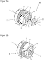
- Figure 5a represents the first preferred embodiment of the prosthesis coupling 10, wherein the first coupling section I is shown in the assembled state with locking ring 13 in an open position and the closure elements 15 ', 15 "held by the rubber band 17 are arranged in an initial position. The closure elements are in the initial position 15 ', 15 "held in their locking socket recesses.
- the recesses A A are designed in such a way that in the starting position the closure elements 15 ', 15 "can be moved at least partially across the recesses A A in a direction perpendicular to the longitudinal axis X.
- the locking elements 15 ', 15 "and inner walls of the locking base 14 form a receiving area A b .
- the receiving area A b between the locking elements 15', 15" and inner walls of the locking base 14 also has a hexagonal and thus a cross-section corresponding to the hexagonal element 20.
- the closure elements 15', 15 move from the FIG Figure 5a starting position shown along the respective guide groove in arrow directions P 1 apart.
- the closure elements 15 ', 15 can each be moved linearly away from the center or the longitudinal axis X.
- the closure elements 15', 15" are due to the The elasticity of the rubber band 17 is deflected back into the starting position and thus back in the direction of the longitudinal axis X, whereby a provisional retention of the connecting component V in the first coupling section I is achieved.
- the opening and closing movement of the closure elements 15 ', 15 "take place in a plane perpendicular to the longitudinal axis X along the double arrow P 1.
- the shape of the connecting component V and the receiving area A b make it possible to mount the second coupling section II in the first coupling section I so that it cannot rotate .
- the hexagonal element 20 preferably has bevelled edges on both sides in the edge region.
- the closure elements 15 ′, 15 ′′ each preferably have a bevel F in order to facilitate the reception of the hexagonal element 20 in the receiving area A b or to create an undercut so that the hexagonal element 20 cannot slip out.
- the bevel F of the closure elements 15 ', 15 "engages around the beveled edges of the hexagonal element 20 when the connecting component V is inserted into the receiving area A b .
- closure elements 15 ′, 15 ′′ here optionally have a centering groove Z that corresponds to the beveled edges of the hexagonal element 20, whereby a completely in the receiving area A b recorded hexagonal element 20 is held almost immovable and secured against rotation.
- the connecting component V When the connecting component V is inserted into the receiving area A b and is held stationary by the closure elements 15 ', 15 "against the tension of the rubber band 17, a provisional holding is achieved.
- the connecting component V and the prosthesis module P attached to it, for example, are with the first Coupling section I is then provisionally connected.
- the elasticity and strength of the rubber band 17 is to be selected so that this provisional holder can be reached.
- the closure elements 15 ', 15 “have the function of clamping jaws that hold the connecting component V in the receiving area A b during the Locking ring 13 is still in the open position. Due to the provisional holder, the prosthesis wearer can let go of the prosthesis module P attached to the connecting component V and does not have to fear falling. Accordingly, the prosthesis wearer has the intact hand free and can carry out further actions without worries.
- the first and second coupling sections I, II can be fixedly connected to one another.
- the locking ring 13 can be brought into a closed position.
- the locking ring 13 By rotating the locking ring 13, here for example by 90 degrees in the direction of arrow P 2 about the longitudinal axis X, the locking ring 13 is moved from the open position into the position shown in FIG Figure 5b Shown closed position of the locking ring 13 brought.
- the connecting component V in Figure 5b omitted so that the locking base 14 and the receiving area A b arranged centrally in the locking base 14 are not covered.
- the locking ring 13 is rotated guided by the at least one guide ball 132 in the at least one guide channel 143, a linear axial displacement against the compression spring element 12 and a rotational movement about the longitudinal axis X resulting.
- This movement takes place due to the curved course of the guide channel 143 in which the guide ball 132 rolls.
- the counterforce generated by the compression spring element 12 is overcome during the rotation of the locking ring 13, while the at least one guide ball 132 ', 132 "rolls along the arcuate guide channel 143. This rotary movement takes place until the at least one guide ball 132', 132" from a starting point to rolled at a point of attachment.
- the locking ring 13 is then in the position shown in FIG Figure 5b shown closed position held.
- a counterforce of the compression spring element 12 acts on the locking ring 13, which is indicated by the dashed arrow.
- a previously provisionally held connecting component V is now held locked in the receiving area A b .
- the closure elements 15 ', 15 "are blocked radially, in particular in their mobility in the direction of arrow P 1 , so that the hexagonal element 20 located in the receiving area A b between the closure elements 15', 15" is in the closed position through the shape of the locking ring 13 - and / or frictional connection is fixed.
- the connecting element V and the prosthesis module P attached to it can advantageously be coupled to the prosthesis socket 1 in six possible radial positions by means of the first coupling section I.
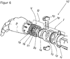
- Fig. 6 shows a second preferred embodiment of the prosthesis coupling 10 'for a prosthesis module P, here in the form of a hand prosthesis, identical components being identified by the same reference numerals.
- a temporary bracket for the Connection component V in the first coupling section I and a subsequent locking of the locking ring 13 in a closed position is possible.
- the first preferred embodiment shown in this embodiment has the connecting component V in addition to the hexagonal element 20 a disk element 18, the hexagonal element 20 being molded onto the disk element 18 and a predetermined breaking point being formed between the hexagonal element 20 and the disk element 18.
- the fixing screws 21 can be seen to be guided only through bores in the disk element 18, while the hexagonal element 20 itself does not comprise any bores.
- the structural design of the second embodiment corresponds to the structural design of the first embodiment of the prosthesis coupling 10 according to the invention Coupling sections I, II separated from each other. If the action of force exceeds a certain value, the disk element 18 breaks off from the hexagonal element 20. The hexagonal element 20 then remains in the receiving area Ab in the locking base 14, held by the locking elements 15 ', 15 ". The disk element 18 remains fixed on the prosthesis module P or the prosthesis socket 1. The prosthesis wearer can repair the prosthesis again by adding a new connecting component V with disk element 18 and hexagonal element 20 is used as the first coupling section I and the broken off hexagonal element 20 is removed from the receiving area A b in the locking base 14.
- the prosthesis coupling 10 can be seen between the prosthesis module P and the disk element 18 include attachable raster disk element 19.
- the raster disk element 19 is preferably mountable to a corresponding raster of the disk element 18 facing the raster disk element 19, so that the hexagonal element 20 formed on the disk element 18 can also be adjusted radially relative to the prosthesis module P. Thanks to this additional fine positioning, specific prosthesis modules can be specifically adapted to customer needs.
- the first coupling section I could be arranged on the prosthesis shaft 1 and the second coupling section II on the prosthesis module P here as well.
- Slightly modified polygonal elements 20 or hexagonal elements 20 as connecting component V are in the Figures 7 shown.
- the hexagonal elements 20 have an optional central hole L, while fastening recesses are arranged concentrically in the disk element 18.
- Figure 7a shows a perspective view of a connecting component V for the second preferred embodiment of the prosthetic prosthesis coupling 10 according to the invention with a predetermined breaking point S formed between hexagonal element 20 and disk element 18.
- the strength of the predetermined breaking point can vary, preferably by choosing the material thickness, the type of material or the design of the notch shape will.
- the section AA shown through the connecting component V shows the predetermined breaking point S in the transition area between the disk element 18 and the hexagonal element 20.
- the wall thicknesses or the transition area from the hexagonal element 20 to the disk element 18 is dimensioned in such a way that when the prosthesis module P or the prosthesis socket 1 is subjected to high loads, a The predetermined breaking occurs at the predetermined breaking point S and not on components of the first coupling section I.
- FIGS. 7c (Section BB through the connecting component) and 7d (section CC through the connecting component) show a respective decreasing dimension or dimensioning of the predetermined breaking point S.
- the dimensions of the predetermined breaking points S of Figures 7b to 7d decrease steadily, which is why the load required to separate the disk element 18 from the hexagonal element 20 and the associated decoupling of the prosthesis module P from the prosthesis socket 1 or the decoupling of the first from the second coupling section I, II of the prosthesis coupling 10 is steadily decreasing.
- the Figures 7b to 7d show that, for example, the dimensioning of the predetermined breaking point S in the transition area between the disk element 18 and the hexagonal element 20 can be varied by the diameter D and the size and bevel of the centrally provided hole L.
- a notch or incision can additionally be provided for the additional weakening of the connecting component V at this point.
- the design measures described above allow the predetermined breaking point S to be varied or to define the force at which the connecting component V breaks, which decouples the second coupling section II from the first coupling section I.
- the contours of the closure elements 15', 15" and the corresponding Connection component V be suitably shaped.
- the closure elements 15 ', 15 "and the connecting component V can only be chamfered on one side.
- the undercut achieved is sufficient to create a linear movement of the connecting component V relative to the provisionally held closure elements 15', 15". If the connecting component V and, for example, a prosthesis module P attached to it are to be uncoupled from the first coupling section I, a linear pull with a sufficiently high pulling force away from the locking ring side must take place.
- connection components V can be colored according to a color coding. The prosthesis can thus be selected with the suitable connecting component V or the suitable predetermined breaking point S depending on the expected load.
- the individual parts of the prosthesis coupling 10 can be produced by means of a 3D printer from rather light material such as thermoplastics, for example from PLA (polylactide), ABS (acrylonitrile-butadiene-styrene) or the like. Since the components can be very light relative to the prosthesis couplings known from the prior art, a target group is underage prosthesis wearers. Due to the growth, the time intervals for adapted components are correspondingly shorter there. However, adult prosthesis wearers also benefit from the simple technical design and the low weight of the prosthesis coupling 10 and a prosthesis with such a prosthesis coupling 10.
- PLA polylactide
- ABS acrylonitrile-butadiene-styrene
Landscapes
- Health & Medical Sciences (AREA)
- Cardiology (AREA)
- Oral & Maxillofacial Surgery (AREA)
- Transplantation (AREA)
- Engineering & Computer Science (AREA)
- Biomedical Technology (AREA)
- Heart & Thoracic Surgery (AREA)
- Vascular Medicine (AREA)
- Life Sciences & Earth Sciences (AREA)
- Animal Behavior & Ethology (AREA)
- General Health & Medical Sciences (AREA)
- Public Health (AREA)
- Veterinary Medicine (AREA)
- Prostheses (AREA)
Claims (15)
- Dispositif d'accouplement de prothèse (10) conçu pour une prothèse, destiné à accoupler et à désaccoupler un module prothétique (P) sur une tige prothétique (1), configurée pour recevoir un moignon d'extrémité (E), le dispositif d'accouplement de prothèse (10) comprenant une première partie d'accouplement (I) et une deuxième partie d'accouplement (II), conçues pour être accouplées l'une à l'autre et désaccouplées, la première partie d'accouplement (I) comportant une base de verrouillage (14) et des éléments de verrouillage (15', 15") et une zone de réception (Ab) sur la base de verrouillage (14), dans laquelle la deuxième partie d'accouplement (II) peut être introduite avec une pièce de liaison (V) pouvant être conçue en étant formée par des parois internes et par les éléments de verrouillage (15', 15"), le dispositif d'accouplement de prothèse (10) comportant un axe longitudinal (X) et la pièce de liaison (V) étant susceptible d'être logée en étant serrée par des forces de rappel à la perpendiculaire de l'axe longitudinal (X)
et la première partie d'accouplement (I) comprenant une bague de blocage (13), laquelle en étant mobile ou rotative de manière linéaire et/ou en rotation par rapport à la base de verrouillage (14) est susceptible d'être amenée dans une position de fermeture, en ce que la pièce de liaison (V) est susceptible d'être logée en étant bloquée dans la zone de réception (Ab),
caractérisé en ce que
les éléments de verrouillage (15', 15") sont maintenus en étant guidés de manière mobile sur des moyens de guidage (142, 144, 16)
et
les forces de rappel sont créées par un moyen de rappel (17) entourant au moins partiellement les éléments de verrouillage (15', 15") et la base de verrouillage (14), suite à quoi, une attache provisoire est créée dans la zone de réception (Ab). - Dispositif d'accouplement de prothèse (10) selon la revendication 1, des encoches de base de verrouillage étant placées dans la base de verrouillage (14), de telle sorte que les éléments de verrouillage (15', 15") puissent être réceptionnés de manière à ce que la périphérie extérieure des éléments de verrouillage (15', 15") puisse être conçue à fleur de la périphérie extérieure de la base de verrouillage (14).
- Dispositif d'accouplement de prothèse (10) selon l'une quelconque des revendications précédentes, le moyen de rappel (17) étant une bande de caoutchouc (17), laquelle entoure les éléments de verrouillage (15', 15") et la base de verrouillage (14).
- Dispositif d'accouplement de prothèse (10) selon l'une quelconque des revendications précédentes, dans la base de verrouillage (14) étant ménagée au moins une rainure de retenue (141) et dans les éléments de verrouillage (15, 15') étant ménagées des deuxièmes et troisièmes rainures des retenue (151', 151"), dans lesquelles le moyen de rappel (17) est logé en s'écoulant.
- Dispositif d'accouplement de prothèse (10) selon l'une quelconque des revendications précédentes, les éléments de verrouillage (15, 15') étant équipés de logements de goupilles de guidage (153', 153") et par l'intermédiaire de goujons de guidage (16', 16") placés dans ces derniers en tant que moyens de guidage, étant logés en étant guidés de manière mobile dans une direction à la perpendiculaire de l'axe longitudinal (X).
- Dispositif d'accouplement de prothèse (10) selon l'une quelconque des revendications précédentes, sur la surface périphérique extérieure de la base de verrouillage (14) étant placé au moins un canal de guidage (143) dans lequel est logée en roulement au moins une bille de guidage (132) maintenue dans un logement de bille de guidage (131) dans la bague de blocage (13), à l'aide de laquelle la bague de blocage (13) peut être amenée d'une position d'ouverture dans une position de fermeture.
- Dispositif d'accouplement de prothèse (10) selon l'une quelconque des revendications précédentes, la première partie d'accouplement (I) comportant un élément à ressort de pression (12) entourant la base de verrouillage (14), lequel exerce une force de pression sur la bague de blocage (13), dans la direction de l'axe longitudinal (X).
- Dispositif d'accouplement de prothèse (10) selon l'une quelconque des revendications précédentes, la bague de blocage (13) comportant des encoches (AA) le long de sa surface périphérique, à travers lesquelles, dans une position d'ouverture réglée de manière rotative de la bague d'arrêt (13), les éléments de verrouillage (15', 15") peuvent être guidés au moins partiellement.
- Dispositif d'accouplement de prothèse (10) selon l'une quelconque des revendications précédentes, les contours de la pièce de liaison (V) et les contours des éléments de verrouillage (15', 15") qui font face à la pièce de liaison (V) comportant des chanfreins (F), destinés à créer une contre-dépouille.
- Dispositif d'accouplement de prothèse (10) selon la revendication 9, les contours de la pièce de liaison (V) et des éléments de verrouillage (15', 15") comportant une rainure de centrage (Z).
- Dispositif d'accouplement de prothèse (10) selon l'une quelconque des revendications précédentes, la pièce de liaison (V) étant réalisée sous la forme d'un élément polygonal (20) pourvu d'une surface de section transversale en polygone présentant au moins trois points d'angle.
- Dispositif d'accouplement de prothèse (10) selon la revendication 11, un élément en forme de disque (18) étant surmoulé sur l'élément polygonal (20) et dans la zone de passage entre l'élément polygonal (20) et l'élément en forme de disque (18) étant conçue une zone de rupture théorique (S).
- Dispositif d'accouplement de prothèse (10) selon la revendication 12, l'élément en forme de disque (18) comportant des encoches de fixation écartées de manière concentrique sur toute l'étendue transversale de l'élément polygonal (20).
- Prothèse, dotée d'un dispositif d'accouplement de prothèse (10) selon l'une quelconque des revendications précédentes, la pièce de liaison (V) de la deuxième partie d'accouplement (II) étant fixée sur un module prothétique (P) et la première partie d'accouplement (I) étant fixée à l'aide d'une bague de fixation (11) sur une tige prothétique (1), de sorte à pouvoir obtenir un accouplement et un désaccouplement du module prothétique (P) sur la tige prothétique (1).
- Prothèse selon la revendication 14, la pièce de liaison (V) étant réalisée sous la forme d'un élément polygonal (20) avec une surface de section transversale en forme de polygone, présentant au moins trois points d'angle, sur lequel est surmoulé un élément en forme de disque (18) et dans la zone de passage entre l'élément polygonal (20) et l'élément en forme de disque (18) étant conçue une zone de rupture théorique (S).
Applications Claiming Priority (2)
| Application Number | Priority Date | Filing Date | Title |
|---|---|---|---|
| CH01254/16A CH712954A1 (de) | 2016-09-26 | 2016-09-26 | Prothesenkupplung für eine Prothese sowie Prothese mit der Prothesenkupplung. |
| PCT/EP2017/073741 WO2018054954A1 (fr) | 2016-09-26 | 2017-09-20 | Dispositif d'accouplement de prothèse conçu pour une prothèse, et prothèse équipée de ce dispositif d'accouplement de prothèse |
Publications (2)
| Publication Number | Publication Date |
|---|---|
| EP3515372A1 EP3515372A1 (fr) | 2019-07-31 |
| EP3515372B1 true EP3515372B1 (fr) | 2020-11-11 |
Family
ID=57583001
Family Applications (1)
| Application Number | Title | Priority Date | Filing Date |
|---|---|---|---|
| EP17772669.2A Not-in-force EP3515372B1 (fr) | 2016-09-26 | 2017-09-20 | Dispositif d'accouplement de prothèse conçu pour une prothèse, et prothèse équipée de ce dispositif d'accouplement de prothèse |
Country Status (3)
| Country | Link |
|---|---|
| EP (1) | EP3515372B1 (fr) |
| CH (1) | CH712954A1 (fr) |
| WO (1) | WO2018054954A1 (fr) |
Families Citing this family (1)
| Publication number | Priority date | Publication date | Assignee | Title |
|---|---|---|---|---|
| CN111568614B (zh) * | 2020-05-22 | 2023-03-31 | 上海理工大学 | 一种模块化多自由度上肢假肢 |
Family Cites Families (3)
| Publication number | Priority date | Publication date | Assignee | Title |
|---|---|---|---|---|
| GB2278281B (en) * | 1993-05-29 | 1997-01-22 | Rehabilitation Services Ltd | Prosthetic wrist |
| US9198778B2 (en) * | 2009-07-17 | 2015-12-01 | Medex International, Inc. | Rotatable prosthetic adapter |
| GB2479532A (en) * | 2010-04-12 | 2011-10-19 | Stanmore Implants Worldwide Ltd | Fail-safe attachment for prosthetic limb |
-
2016
- 2016-09-26 CH CH01254/16A patent/CH712954A1/de unknown
-
2017
- 2017-09-20 EP EP17772669.2A patent/EP3515372B1/fr not_active Not-in-force
- 2017-09-20 WO PCT/EP2017/073741 patent/WO2018054954A1/fr not_active Ceased
Non-Patent Citations (1)
| Title |
|---|
| None * |
Also Published As
| Publication number | Publication date |
|---|---|
| WO2018054954A1 (fr) | 2018-03-29 |
| EP3515372A1 (fr) | 2019-07-31 |
| CH712954A1 (de) | 2018-03-29 |
Similar Documents
| Publication | Publication Date | Title |
|---|---|---|
| DE7033152U (de) | Schnellwechselfutter fuer werkzeuge. | |
| EP0271782B1 (fr) | Etau à ressort | |
| DE4224296A1 (de) | Mechanische Spannvorrichtung mit Adapterteil | |
| DE102007022186A1 (de) | Adapter zum Betreiben einer Lochsäge an einer Antriebsmaschine | |
| WO2015036353A2 (fr) | Dispositif de fixation | |
| DE102016117538A1 (de) | Elektrischer Steckverbinder | |
| DE10104833A1 (de) | Magnetverschluss | |
| EP0712802A2 (fr) | Support pour bobines de fil textile tournant à grande vitesse dans les machines textile ainsi que l'adaptateur de bobine associé | |
| DE3020838C2 (fr) | ||
| AT393302B (de) | Vorrichtung zur verbindung zweier werkzeugteile | |
| EP2929992A1 (fr) | Couteau et logement de couteau pour une machine à découper | |
| EP2476500A1 (fr) | Elément de fixation pour un composant en forme de moyeu | |
| EP0275441B1 (fr) | Dispositif de serrage | |
| EP3412388B1 (fr) | Moyen de serrage interne comprenant un anneau de segment de serrage | |
| EP1651133B1 (fr) | Element d'implant dentaire | |
| DE102009014084A1 (de) | Scharnier für einen Kraftwagen | |
| DE102020115021A1 (de) | Vorrichtung zum Verbinden zweier röhrenförmiger Objekte | |
| EP1709931B1 (fr) | Organe moteur, en particulier pièce à main dentaire avec un accouplement détachable pour un porte-outil | |
| DE19923006C2 (de) | Spannfutter für auswechselbare Werkzeugeinsätze | |
| DE102017116011B3 (de) | Steckachse für Zweiräder | |
| EP2861890B1 (fr) | Dispositif de réglage du châssis d'un véhicule | |
| EP1888280B1 (fr) | Liaison entre deux parties d'outil | |
| EP3515372A1 (fr) | Dispositif d'accouplement de prothèse conçu pour une prothèse, et prothèse équipée de ce dispositif d'accouplement de prothèse | |
| DE6941979U (de) | Rollenpolierwerkzeug. | |
| EP1140431A1 (fr) | Mandrin de serrage destine a des composants d'outil |
Legal Events
| Date | Code | Title | Description |
|---|---|---|---|
| STAA | Information on the status of an ep patent application or granted ep patent |
Free format text: STATUS: UNKNOWN |
|
| STAA | Information on the status of an ep patent application or granted ep patent |
Free format text: STATUS: THE INTERNATIONAL PUBLICATION HAS BEEN MADE |
|
| PUAI | Public reference made under article 153(3) epc to a published international application that has entered the european phase |
Free format text: ORIGINAL CODE: 0009012 |
|
| STAA | Information on the status of an ep patent application or granted ep patent |
Free format text: STATUS: REQUEST FOR EXAMINATION WAS MADE |
|
| 17P | Request for examination filed |
Effective date: 20190405 |
|
| AK | Designated contracting states |
Kind code of ref document: A1 Designated state(s): AL AT BE BG CH CY CZ DE DK EE ES FI FR GB GR HR HU IE IS IT LI LT LU LV MC MK MT NL NO PL PT RO RS SE SI SK SM TR |
|
| AX | Request for extension of the european patent |
Extension state: BA ME |
|
| DAV | Request for validation of the european patent (deleted) | ||
| DAX | Request for extension of the european patent (deleted) | ||
| GRAP | Despatch of communication of intention to grant a patent |
Free format text: ORIGINAL CODE: EPIDOSNIGR1 |
|
| STAA | Information on the status of an ep patent application or granted ep patent |
Free format text: STATUS: GRANT OF PATENT IS INTENDED |
|
| INTG | Intention to grant announced |
Effective date: 20200604 |
|
| RIN1 | Information on inventor provided before grant (corrected) |
Inventor name: SCHOLLENBERGER, FABIAN |
|
| GRAS | Grant fee paid |
Free format text: ORIGINAL CODE: EPIDOSNIGR3 |
|
| GRAA | (expected) grant |
Free format text: ORIGINAL CODE: 0009210 |
|
| STAA | Information on the status of an ep patent application or granted ep patent |
Free format text: STATUS: THE PATENT HAS BEEN GRANTED |
|
| AK | Designated contracting states |
Kind code of ref document: B1 Designated state(s): AL AT BE BG CH CY CZ DE DK EE ES FI FR GB GR HR HU IE IS IT LI LT LU LV MC MK MT NL NO PL PT RO RS SE SI SK SM TR |
|
| REG | Reference to a national code |
Ref country code: GB Ref legal event code: FG4D Free format text: NOT ENGLISH |
|
| REG | Reference to a national code |
Ref country code: CH Ref legal event code: EP |
|
| REG | Reference to a national code |
Ref country code: AT Ref legal event code: REF Ref document number: 1332745 Country of ref document: AT Kind code of ref document: T Effective date: 20201115 |
|
| REG | Reference to a national code |
Ref country code: DE Ref legal event code: R096 Ref document number: 502017008190 Country of ref document: DE |
|
| REG | Reference to a national code |
Ref country code: IE Ref legal event code: FG4D Free format text: LANGUAGE OF EP DOCUMENT: GERMAN |
|
| REG | Reference to a national code |
Ref country code: CH Ref legal event code: NV Representative=s name: KELLER SCHNEIDER PATENT- UND MARKENANWAELTE AG, CH |
|
| REG | Reference to a national code |
Ref country code: NL Ref legal event code: MP Effective date: 20201111 |
|
| PG25 | Lapsed in a contracting state [announced via postgrant information from national office to epo] |
Ref country code: RS Free format text: LAPSE BECAUSE OF FAILURE TO SUBMIT A TRANSLATION OF THE DESCRIPTION OR TO PAY THE FEE WITHIN THE PRESCRIBED TIME-LIMIT Effective date: 20201111 Ref country code: PT Free format text: LAPSE BECAUSE OF FAILURE TO SUBMIT A TRANSLATION OF THE DESCRIPTION OR TO PAY THE FEE WITHIN THE PRESCRIBED TIME-LIMIT Effective date: 20210311 Ref country code: FI Free format text: LAPSE BECAUSE OF FAILURE TO SUBMIT A TRANSLATION OF THE DESCRIPTION OR TO PAY THE FEE WITHIN THE PRESCRIBED TIME-LIMIT Effective date: 20201111 Ref country code: NO Free format text: LAPSE BECAUSE OF FAILURE TO SUBMIT A TRANSLATION OF THE DESCRIPTION OR TO PAY THE FEE WITHIN THE PRESCRIBED TIME-LIMIT Effective date: 20210211 Ref country code: GR Free format text: LAPSE BECAUSE OF FAILURE TO SUBMIT A TRANSLATION OF THE DESCRIPTION OR TO PAY THE FEE WITHIN THE PRESCRIBED TIME-LIMIT Effective date: 20210212 |
|
| PG25 | Lapsed in a contracting state [announced via postgrant information from national office to epo] |
Ref country code: SE Free format text: LAPSE BECAUSE OF FAILURE TO SUBMIT A TRANSLATION OF THE DESCRIPTION OR TO PAY THE FEE WITHIN THE PRESCRIBED TIME-LIMIT Effective date: 20201111 Ref country code: LV Free format text: LAPSE BECAUSE OF FAILURE TO SUBMIT A TRANSLATION OF THE DESCRIPTION OR TO PAY THE FEE WITHIN THE PRESCRIBED TIME-LIMIT Effective date: 20201111 Ref country code: PL Free format text: LAPSE BECAUSE OF FAILURE TO SUBMIT A TRANSLATION OF THE DESCRIPTION OR TO PAY THE FEE WITHIN THE PRESCRIBED TIME-LIMIT Effective date: 20201111 Ref country code: IS Free format text: LAPSE BECAUSE OF FAILURE TO SUBMIT A TRANSLATION OF THE DESCRIPTION OR TO PAY THE FEE WITHIN THE PRESCRIBED TIME-LIMIT Effective date: 20210311 Ref country code: BG Free format text: LAPSE BECAUSE OF FAILURE TO SUBMIT A TRANSLATION OF THE DESCRIPTION OR TO PAY THE FEE WITHIN THE PRESCRIBED TIME-LIMIT Effective date: 20210211 |
|
| REG | Reference to a national code |
Ref country code: LT Ref legal event code: MG9D |
|
| PG25 | Lapsed in a contracting state [announced via postgrant information from national office to epo] |
Ref country code: HR Free format text: LAPSE BECAUSE OF FAILURE TO SUBMIT A TRANSLATION OF THE DESCRIPTION OR TO PAY THE FEE WITHIN THE PRESCRIBED TIME-LIMIT Effective date: 20201111 |
|
| PG25 | Lapsed in a contracting state [announced via postgrant information from national office to epo] |
Ref country code: CZ Free format text: LAPSE BECAUSE OF FAILURE TO SUBMIT A TRANSLATION OF THE DESCRIPTION OR TO PAY THE FEE WITHIN THE PRESCRIBED TIME-LIMIT Effective date: 20201111 Ref country code: EE Free format text: LAPSE BECAUSE OF FAILURE TO SUBMIT A TRANSLATION OF THE DESCRIPTION OR TO PAY THE FEE WITHIN THE PRESCRIBED TIME-LIMIT Effective date: 20201111 Ref country code: LT Free format text: LAPSE BECAUSE OF FAILURE TO SUBMIT A TRANSLATION OF THE DESCRIPTION OR TO PAY THE FEE WITHIN THE PRESCRIBED TIME-LIMIT Effective date: 20201111 Ref country code: SM Free format text: LAPSE BECAUSE OF FAILURE TO SUBMIT A TRANSLATION OF THE DESCRIPTION OR TO PAY THE FEE WITHIN THE PRESCRIBED TIME-LIMIT Effective date: 20201111 Ref country code: RO Free format text: LAPSE BECAUSE OF FAILURE TO SUBMIT A TRANSLATION OF THE DESCRIPTION OR TO PAY THE FEE WITHIN THE PRESCRIBED TIME-LIMIT Effective date: 20201111 Ref country code: SK Free format text: LAPSE BECAUSE OF FAILURE TO SUBMIT A TRANSLATION OF THE DESCRIPTION OR TO PAY THE FEE WITHIN THE PRESCRIBED TIME-LIMIT Effective date: 20201111 |
|
| REG | Reference to a national code |
Ref country code: DE Ref legal event code: R097 Ref document number: 502017008190 Country of ref document: DE |
|
| PG25 | Lapsed in a contracting state [announced via postgrant information from national office to epo] |
Ref country code: DK Free format text: LAPSE BECAUSE OF FAILURE TO SUBMIT A TRANSLATION OF THE DESCRIPTION OR TO PAY THE FEE WITHIN THE PRESCRIBED TIME-LIMIT Effective date: 20201111 |
|
| PLBE | No opposition filed within time limit |
Free format text: ORIGINAL CODE: 0009261 |
|
| STAA | Information on the status of an ep patent application or granted ep patent |
Free format text: STATUS: NO OPPOSITION FILED WITHIN TIME LIMIT |
|
| 26N | No opposition filed |
Effective date: 20210812 |
|
| PG25 | Lapsed in a contracting state [announced via postgrant information from national office to epo] |
Ref country code: NL Free format text: LAPSE BECAUSE OF FAILURE TO SUBMIT A TRANSLATION OF THE DESCRIPTION OR TO PAY THE FEE WITHIN THE PRESCRIBED TIME-LIMIT Effective date: 20201111 Ref country code: AL Free format text: LAPSE BECAUSE OF FAILURE TO SUBMIT A TRANSLATION OF THE DESCRIPTION OR TO PAY THE FEE WITHIN THE PRESCRIBED TIME-LIMIT Effective date: 20201111 Ref country code: IT Free format text: LAPSE BECAUSE OF FAILURE TO SUBMIT A TRANSLATION OF THE DESCRIPTION OR TO PAY THE FEE WITHIN THE PRESCRIBED TIME-LIMIT Effective date: 20201111 |
|
| PG25 | Lapsed in a contracting state [announced via postgrant information from national office to epo] |
Ref country code: SI Free format text: LAPSE BECAUSE OF FAILURE TO SUBMIT A TRANSLATION OF THE DESCRIPTION OR TO PAY THE FEE WITHIN THE PRESCRIBED TIME-LIMIT Effective date: 20201111 |
|
| PGFP | Annual fee paid to national office [announced via postgrant information from national office to epo] |
Ref country code: DE Payment date: 20210810 Year of fee payment: 5 |
|
| PG25 | Lapsed in a contracting state [announced via postgrant information from national office to epo] |
Ref country code: ES Free format text: LAPSE BECAUSE OF FAILURE TO SUBMIT A TRANSLATION OF THE DESCRIPTION OR TO PAY THE FEE WITHIN THE PRESCRIBED TIME-LIMIT Effective date: 20201111 |
|
| PGFP | Annual fee paid to national office [announced via postgrant information from national office to epo] |
Ref country code: CH Payment date: 20211229 Year of fee payment: 5 |
|
| REG | Reference to a national code |
Ref country code: BE Ref legal event code: MM Effective date: 20210930 |
|
| GBPC | Gb: european patent ceased through non-payment of renewal fee |
Effective date: 20210920 |
|
| PG25 | Lapsed in a contracting state [announced via postgrant information from national office to epo] |
Ref country code: IS Free format text: LAPSE BECAUSE OF FAILURE TO SUBMIT A TRANSLATION OF THE DESCRIPTION OR TO PAY THE FEE WITHIN THE PRESCRIBED TIME-LIMIT Effective date: 20210311 Ref country code: MC Free format text: LAPSE BECAUSE OF FAILURE TO SUBMIT A TRANSLATION OF THE DESCRIPTION OR TO PAY THE FEE WITHIN THE PRESCRIBED TIME-LIMIT Effective date: 20201111 |
|
| PG25 | Lapsed in a contracting state [announced via postgrant information from national office to epo] |
Ref country code: LU Free format text: LAPSE BECAUSE OF NON-PAYMENT OF DUE FEES Effective date: 20210920 Ref country code: IE Free format text: LAPSE BECAUSE OF NON-PAYMENT OF DUE FEES Effective date: 20210920 Ref country code: GB Free format text: LAPSE BECAUSE OF NON-PAYMENT OF DUE FEES Effective date: 20210920 Ref country code: FR Free format text: LAPSE BECAUSE OF NON-PAYMENT OF DUE FEES Effective date: 20210930 Ref country code: BE Free format text: LAPSE BECAUSE OF NON-PAYMENT OF DUE FEES Effective date: 20210930 |
|
| REG | Reference to a national code |
Ref country code: DE Ref legal event code: R119 Ref document number: 502017008190 Country of ref document: DE |
|
| REG | Reference to a national code |
Ref country code: CH Ref legal event code: PL |
|
| PG25 | Lapsed in a contracting state [announced via postgrant information from national office to epo] |
Ref country code: CY Free format text: LAPSE BECAUSE OF FAILURE TO SUBMIT A TRANSLATION OF THE DESCRIPTION OR TO PAY THE FEE WITHIN THE PRESCRIBED TIME-LIMIT Effective date: 20201111 |
|
| PG25 | Lapsed in a contracting state [announced via postgrant information from national office to epo] |
Ref country code: LI Free format text: LAPSE BECAUSE OF NON-PAYMENT OF DUE FEES Effective date: 20220930 Ref country code: HU Free format text: LAPSE BECAUSE OF FAILURE TO SUBMIT A TRANSLATION OF THE DESCRIPTION OR TO PAY THE FEE WITHIN THE PRESCRIBED TIME-LIMIT; INVALID AB INITIO Effective date: 20170920 Ref country code: DE Free format text: LAPSE BECAUSE OF NON-PAYMENT OF DUE FEES Effective date: 20230401 Ref country code: CH Free format text: LAPSE BECAUSE OF NON-PAYMENT OF DUE FEES Effective date: 20220930 |
|
| REG | Reference to a national code |
Ref country code: AT Ref legal event code: MM01 Ref document number: 1332745 Country of ref document: AT Kind code of ref document: T Effective date: 20220920 |
|
| PG25 | Lapsed in a contracting state [announced via postgrant information from national office to epo] |
Ref country code: AT Free format text: LAPSE BECAUSE OF NON-PAYMENT OF DUE FEES Effective date: 20220920 |
|
| PG25 | Lapsed in a contracting state [announced via postgrant information from national office to epo] |
Ref country code: MK Free format text: LAPSE BECAUSE OF FAILURE TO SUBMIT A TRANSLATION OF THE DESCRIPTION OR TO PAY THE FEE WITHIN THE PRESCRIBED TIME-LIMIT Effective date: 20201111 |
|
| PG25 | Lapsed in a contracting state [announced via postgrant information from national office to epo] |
Ref country code: TR Free format text: LAPSE BECAUSE OF FAILURE TO SUBMIT A TRANSLATION OF THE DESCRIPTION OR TO PAY THE FEE WITHIN THE PRESCRIBED TIME-LIMIT Effective date: 20201111 |
|
| PG25 | Lapsed in a contracting state [announced via postgrant information from national office to epo] |
Ref country code: MT Free format text: LAPSE BECAUSE OF FAILURE TO SUBMIT A TRANSLATION OF THE DESCRIPTION OR TO PAY THE FEE WITHIN THE PRESCRIBED TIME-LIMIT Effective date: 20201111 |