EP3515520B1 - Vorrichtungen und verfahren zur vaskulären hyperperfusion des extravaskulären raums - Google Patents
Vorrichtungen und verfahren zur vaskulären hyperperfusion des extravaskulären raums Download PDFInfo
- Publication number
- EP3515520B1 EP3515520B1 EP17851976.5A EP17851976A EP3515520B1 EP 3515520 B1 EP3515520 B1 EP 3515520B1 EP 17851976 A EP17851976 A EP 17851976A EP 3515520 B1 EP3515520 B1 EP 3515520B1
- Authority
- EP
- European Patent Office
- Prior art keywords
- cannula
- plunger
- blood
- balloon
- lumen
- Prior art date
- Legal status (The legal status is an assumption and is not a legal conclusion. Google has not performed a legal analysis and makes no representation as to the accuracy of the status listed.)
- Active
Links
Images


Classifications
-
- A—HUMAN NECESSITIES
- A61—MEDICAL OR VETERINARY SCIENCE; HYGIENE
- A61M—DEVICES FOR INTRODUCING MEDIA INTO, OR ONTO, THE BODY; DEVICES FOR TRANSDUCING BODY MEDIA OR FOR TAKING MEDIA FROM THE BODY; DEVICES FOR PRODUCING OR ENDING SLEEP OR STUPOR
- A61M1/00—Suction or pumping devices for medical purposes; Devices for carrying-off, for treatment of, or for carrying-over, body-liquids; Drainage systems
- A61M1/36—Other treatment of blood in a by-pass of the natural circulatory system, e.g. temperature adaptation, irradiation ; Extra-corporeal blood circuits
- A61M1/3613—Reperfusion, e.g. of the coronary vessels, e.g. retroperfusion
-
- A—HUMAN NECESSITIES
- A61—MEDICAL OR VETERINARY SCIENCE; HYGIENE
- A61M—DEVICES FOR INTRODUCING MEDIA INTO, OR ONTO, THE BODY; DEVICES FOR TRANSDUCING BODY MEDIA OR FOR TAKING MEDIA FROM THE BODY; DEVICES FOR PRODUCING OR ENDING SLEEP OR STUPOR
- A61M1/00—Suction or pumping devices for medical purposes; Devices for carrying-off, for treatment of, or for carrying-over, body-liquids; Drainage systems
- A61M1/36—Other treatment of blood in a by-pass of the natural circulatory system, e.g. temperature adaptation, irradiation ; Extra-corporeal blood circuits
- A61M1/3615—Cleaning blood contaminated by local chemotherapy of a body part temporarily isolated from the blood circuit
-
- A—HUMAN NECESSITIES
- A61—MEDICAL OR VETERINARY SCIENCE; HYGIENE
- A61M—DEVICES FOR INTRODUCING MEDIA INTO, OR ONTO, THE BODY; DEVICES FOR TRANSDUCING BODY MEDIA OR FOR TAKING MEDIA FROM THE BODY; DEVICES FOR PRODUCING OR ENDING SLEEP OR STUPOR
- A61M1/00—Suction or pumping devices for medical purposes; Devices for carrying-off, for treatment of, or for carrying-over, body-liquids; Drainage systems
- A61M1/36—Other treatment of blood in a by-pass of the natural circulatory system, e.g. temperature adaptation, irradiation ; Extra-corporeal blood circuits
- A61M1/3621—Extra-corporeal blood circuits
- A61M1/3639—Blood pressure control, pressure transducers specially adapted therefor
-
- A—HUMAN NECESSITIES
- A61—MEDICAL OR VETERINARY SCIENCE; HYGIENE
- A61M—DEVICES FOR INTRODUCING MEDIA INTO, OR ONTO, THE BODY; DEVICES FOR TRANSDUCING BODY MEDIA OR FOR TAKING MEDIA FROM THE BODY; DEVICES FOR PRODUCING OR ENDING SLEEP OR STUPOR
- A61M1/00—Suction or pumping devices for medical purposes; Devices for carrying-off, for treatment of, or for carrying-over, body-liquids; Drainage systems
- A61M1/36—Other treatment of blood in a by-pass of the natural circulatory system, e.g. temperature adaptation, irradiation ; Extra-corporeal blood circuits
- A61M1/3621—Extra-corporeal blood circuits
- A61M1/3653—Interfaces between patient blood circulation and extra-corporal blood circuit
- A61M1/3655—Arterio-venous shunts or fistulae
-
- A—HUMAN NECESSITIES
- A61—MEDICAL OR VETERINARY SCIENCE; HYGIENE
- A61M—DEVICES FOR INTRODUCING MEDIA INTO, OR ONTO, THE BODY; DEVICES FOR TRANSDUCING BODY MEDIA OR FOR TAKING MEDIA FROM THE BODY; DEVICES FOR PRODUCING OR ENDING SLEEP OR STUPOR
- A61M25/00—Catheters; Hollow probes
- A61M25/01—Introducing, guiding, advancing, emplacing or holding catheters
- A61M25/09—Guide wires
-
- A—HUMAN NECESSITIES
- A61—MEDICAL OR VETERINARY SCIENCE; HYGIENE
- A61M—DEVICES FOR INTRODUCING MEDIA INTO, OR ONTO, THE BODY; DEVICES FOR TRANSDUCING BODY MEDIA OR FOR TAKING MEDIA FROM THE BODY; DEVICES FOR PRODUCING OR ENDING SLEEP OR STUPOR
- A61M25/00—Catheters; Hollow probes
- A61M25/10—Balloon catheters
- A61M25/1011—Multiple balloon catheters
-
- A—HUMAN NECESSITIES
- A61—MEDICAL OR VETERINARY SCIENCE; HYGIENE
- A61M—DEVICES FOR INTRODUCING MEDIA INTO, OR ONTO, THE BODY; DEVICES FOR TRANSDUCING BODY MEDIA OR FOR TAKING MEDIA FROM THE BODY; DEVICES FOR PRODUCING OR ENDING SLEEP OR STUPOR
- A61M39/00—Tubes, tube connectors, tube couplings, valves, access sites or the like, specially adapted for medical use
- A61M39/02—Access sites
- A61M39/0208—Subcutaneous access sites for injecting or removing fluids
-
- A—HUMAN NECESSITIES
- A61—MEDICAL OR VETERINARY SCIENCE; HYGIENE
- A61M—DEVICES FOR INTRODUCING MEDIA INTO, OR ONTO, THE BODY; DEVICES FOR TRANSDUCING BODY MEDIA OR FOR TAKING MEDIA FROM THE BODY; DEVICES FOR PRODUCING OR ENDING SLEEP OR STUPOR
- A61M5/00—Devices for bringing media into the body in a subcutaneous, intra-vascular or intramuscular way; Accessories therefor, e.g. filling or cleaning devices, arm-rests
- A61M5/14—Infusion devices, e.g. infusing by gravity; Blood infusion; Accessories therefor
- A61M5/142—Pressure infusion, e.g. using pumps
- A61M5/145—Pressure infusion, e.g. using pumps using pressurised reservoirs, e.g. pressurised by means of pistons
- A61M5/1452—Pressure infusion, e.g. using pumps using pressurised reservoirs, e.g. pressurised by means of pistons pressurised by means of pistons
-
- A—HUMAN NECESSITIES
- A61—MEDICAL OR VETERINARY SCIENCE; HYGIENE
- A61M—DEVICES FOR INTRODUCING MEDIA INTO, OR ONTO, THE BODY; DEVICES FOR TRANSDUCING BODY MEDIA OR FOR TAKING MEDIA FROM THE BODY; DEVICES FOR PRODUCING OR ENDING SLEEP OR STUPOR
- A61M25/00—Catheters; Hollow probes
- A61M25/01—Introducing, guiding, advancing, emplacing or holding catheters
- A61M25/09—Guide wires
- A61M2025/09008—Guide wires having a balloon
-
- A—HUMAN NECESSITIES
- A61—MEDICAL OR VETERINARY SCIENCE; HYGIENE
- A61M—DEVICES FOR INTRODUCING MEDIA INTO, OR ONTO, THE BODY; DEVICES FOR TRANSDUCING BODY MEDIA OR FOR TAKING MEDIA FROM THE BODY; DEVICES FOR PRODUCING OR ENDING SLEEP OR STUPOR
- A61M25/00—Catheters; Hollow probes
- A61M25/10—Balloon catheters
- A61M2025/1043—Balloon catheters with special features or adapted for special applications
- A61M2025/105—Balloon catheters with special features or adapted for special applications having a balloon suitable for drug delivery, e.g. by using holes for delivery, drug coating or membranes
-
- A—HUMAN NECESSITIES
- A61—MEDICAL OR VETERINARY SCIENCE; HYGIENE
- A61M—DEVICES FOR INTRODUCING MEDIA INTO, OR ONTO, THE BODY; DEVICES FOR TRANSDUCING BODY MEDIA OR FOR TAKING MEDIA FROM THE BODY; DEVICES FOR PRODUCING OR ENDING SLEEP OR STUPOR
- A61M25/00—Catheters; Hollow probes
- A61M25/10—Balloon catheters
- A61M2025/1043—Balloon catheters with special features or adapted for special applications
- A61M2025/1052—Balloon catheters with special features or adapted for special applications for temporarily occluding a vessel for isolating a sector
-
- A—HUMAN NECESSITIES
- A61—MEDICAL OR VETERINARY SCIENCE; HYGIENE
- A61M—DEVICES FOR INTRODUCING MEDIA INTO, OR ONTO, THE BODY; DEVICES FOR TRANSDUCING BODY MEDIA OR FOR TAKING MEDIA FROM THE BODY; DEVICES FOR PRODUCING OR ENDING SLEEP OR STUPOR
- A61M39/00—Tubes, tube connectors, tube couplings, valves, access sites or the like, specially adapted for medical use
- A61M39/02—Access sites
- A61M2039/0205—Access sites for injecting media
-
- A—HUMAN NECESSITIES
- A61—MEDICAL OR VETERINARY SCIENCE; HYGIENE
- A61M—DEVICES FOR INTRODUCING MEDIA INTO, OR ONTO, THE BODY; DEVICES FOR TRANSDUCING BODY MEDIA OR FOR TAKING MEDIA FROM THE BODY; DEVICES FOR PRODUCING OR ENDING SLEEP OR STUPOR
- A61M2210/00—Anatomical parts of the body
- A61M2210/06—Head
- A61M2210/0693—Brain, cerebrum
-
- A—HUMAN NECESSITIES
- A61—MEDICAL OR VETERINARY SCIENCE; HYGIENE
- A61M—DEVICES FOR INTRODUCING MEDIA INTO, OR ONTO, THE BODY; DEVICES FOR TRANSDUCING BODY MEDIA OR FOR TAKING MEDIA FROM THE BODY; DEVICES FOR PRODUCING OR ENDING SLEEP OR STUPOR
- A61M2210/00—Anatomical parts of the body
- A61M2210/10—Trunk
- A61M2210/1007—Breast; mammary
-
- A—HUMAN NECESSITIES
- A61—MEDICAL OR VETERINARY SCIENCE; HYGIENE
- A61M—DEVICES FOR INTRODUCING MEDIA INTO, OR ONTO, THE BODY; DEVICES FOR TRANSDUCING BODY MEDIA OR FOR TAKING MEDIA FROM THE BODY; DEVICES FOR PRODUCING OR ENDING SLEEP OR STUPOR
- A61M2210/00—Anatomical parts of the body
- A61M2210/10—Trunk
- A61M2210/1042—Alimentary tract
- A61M2210/1071—Liver; Hepar
-
- A—HUMAN NECESSITIES
- A61—MEDICAL OR VETERINARY SCIENCE; HYGIENE
- A61M—DEVICES FOR INTRODUCING MEDIA INTO, OR ONTO, THE BODY; DEVICES FOR TRANSDUCING BODY MEDIA OR FOR TAKING MEDIA FROM THE BODY; DEVICES FOR PRODUCING OR ENDING SLEEP OR STUPOR
- A61M39/00—Tubes, tube connectors, tube couplings, valves, access sites or the like, specially adapted for medical use
- A61M39/10—Tube connectors; Tube couplings
- A61M39/12—Tube connectors; Tube couplings for joining a flexible tube to a rigid attachment
Definitions
- the present invention relates to improvements in vascular isolation of organs and segments thereof and, in particular, to improved vascular access devices, usable in the context of vascular isolation of human extravascular spaces in organs and segments thereof, so as to enhance delivery and activity of therapeutic agents, such as chemotherapeutic agents and stem cells, to those extravascular spaces.
- the present invention relates to devices for engaging with vascular spaces and segments thereof.
- the end of the cannula and/or plug includes edges or protrusions or recesses that extend into the vein or artery or that result in an area of dead space in the cannula.
- Protrusions and recesses present a formation that potentially allows blood to pool and stagnate giving rise to the conditions where thrombosis can occur.
- Dead space also gives rise to an area where blood can pool and stagnate also presenting a situation where thrombosis can occur.
- the dead space may also present an area where gas collects giving rise to the risk of a gas embolism forming.
- the access devices used in such treatments or therapies typically comprise a cannula with one end connected to the circulatory system of a patient, and adaptor ports on the other end connected to a blood flow pump or other injection device.
- the isolation system When not in use, the isolation system has relied on a plunger that is slidable within the cavity of the cannula to close access to the cavity and so to prevent fluid communication between the circulatory system and any of the ports of the access device.
- Such access devices may be referred to as single lumen access devices.
- US Patent No. 7,766,853 and US Patent No. 8,419,672 describe such access devices for remote access isolation systems. Related access devices and systems are described in US Patent No. 9,078,982 .
- US Patent No. 6,699,231 discloses methods and apparatus for perfusion of isolated tissue structure. Isolation is effected by endovascularly positioning catheters having occlusion balloons within the arteries or other blood vessels which supply blood to the organ. Similarly, blood flow from the organ back to the patient's circulatory system is blocked by endovascularly positioning one or more catheters carrying occlusion members within the veins or other blood vessels leading from the organ.
- US Patent Application No. 2014/207060 discloses a system for perfusing a localized site within a body including a catheter assembly having a venous access line that is adapted to deliver perfusate to the localized site, a venous or arterial drainage line adapted to drain perfusate from the localized site, and an occlusion device adapted to prevent some or substantially all physiological blood flow between the localized site and the systemic circulation of the body during and in the course of perfusing and draining perfusate to and from the localized site.
- the system may include a blood circuit associated with the catheter assembly to facilitate blood conditioning for use as the perfusate, in the course of a controlled perfusion and/or drainage of untreated, treated, or inactivated treated blood to and from the localized site.
- a venous or arterial access such as a cannula
- a cannula When a venous or arterial access, such as a cannula, is connected to a patient's blood vessel at a perpendicular angle, the tip of a plunger can be slid through the cavity or lumen of the cannula until it reaches the location where the proximal end of the cannula is connected to the wall of the vessel.
- the plunger can thus, after use of the cannula, completely prevent the filling of the patient's blood into the lumen of the cannula, thereby avoiding fluid stasis which may otherwise cause thrombosis.
- the conventional cylindrical shape of the tip of the plunger is not capable of preventing the filling of a small amount of blood into a lower part (called “the dead space") of the lumen of the cannula unless the tip is slid further through the lumen of the cannula and a leading part of the tip protrudes into the lumen of the vessel.
- the dead space a lower part of the cannula's lumen or.
- the dead space is occupied by the plunger tip, such a protrusion of the leading part of the tip into the vessel's lumen, can be responsible for haemodynamic disturbances, including fluid stasis, within the patient's circulatory system that could result in thrombotic events.
- a single lumen access device of the kind described in these patents such as a cannula
- the tip of a plunger can be slid through the cavity or lumen of the cannula until it reaches the location where the proximal end of the cannula is connected to the wall of the vessel.
- the plunger can thus, after use of the cannula, completely prevent the filling of the patient's blood into the lumen of the cannula, thereby avoiding fluid stasis which may otherwise cause thrombosis.
- the conventional cylindrical shape of the tip of the plunger is not capable of preventing the filling of a small amount of blood into a lower part (called “the dead space") of the lumen of the cannula unless the tip is slid further through the lumen of the cannula and a leading part of the tip protrudes into the lumen of the vessel.
- Such a dead space within the lower part of the cannula's lumen or, if the dead space is occupied by the plunger tip, such a protrusion of the leading part of the tip into the vessel's lumen, can be responsible for haemodynamic disturbances, including fluid stasis, within the patient's circulatory system that could result in thrombotic events.
- access devices with multi-access treatment caps are known, as shown in Figure 51 of US Patent No. 9,078,982 by the present inventor.
- those access devices with multi-access treatment caps have access ports which are such that only a single catheter may be received through a selected access port and then through the lumen of the access device, and therefore each such device can only facilitate either an outflow from the circulatory system to a blood flow pump or an inflow from a blood flow pump in the circulatory system, but not both. That is, those access devices with multi-access treatment caps cannot facilitate two or more inflow and outflow catheters at any one time because the lumen of those devices is unable to receive two or more catheters. Additionally, those multi-access treatment caps do not enable a catheter to be directed into specific positions with use of the multi-access treatment cap.
- An alternative approach is to remove the blood containing the chemotherapeutic agent and use various extracorporeal filters to neutralize the agent before systemic recirculation. The aim in that situation is to minimise the toxic side effects when the blood containing the chemotherapeutic agent is released into the systemic circulation.
- This type of approach may be done operatively in the liver by cannulating the portal vein and the hepatic artery of the liver, using pumps to recirculate the agent and using an extracorporeal filter to minimise the systemic effects. This is called "isolated hepatic infusion”.
- the inevitable effect of hyperperfusing therapeutic agents regionally to a desired intravascular space is that the agents will then move into the interstitial space from where they can enter not only the target area but also the draining lymphatic channels and lymph nodes.
- the approach has important ramifications in the treatment of neoplasia, as many malignant cells invade the lymphatic channels, migrate into the lymph nodes, multiply and then embolise via the thoracic duct before they move into the vascular system from where they spread systemically. Lymph nodes that are involved are notoriously difficult to treat because of their small size. Tumour recurrence often arises from residual tumours in lymph nodes and among lymph cells.
- tumours are also known to induce a higher interstitial pressure partly due to a surrounding pseudo-capsule related to compression of normal structure and or secondary inflammatory effects.
- malignant cells that do not multiply and so those therapeutic agents which mainly affect cell division will have little or no effect on such cells.
- the access devices used in such remote access isolation systems for regional hyperperfusion to a target area and for therapies or treatments where arterial or venous engagement for extended periods is required include cannulas, catheters (and especially balloon catheter systems), balloons, plungers, adaptor ports and other devices required for these therapies or treatments.
- the access devices used in such systems typically comprise a cannula with one end connected to the circulatory system of a patient, and adaptor ports on the other end connected to a blood flow pump.
- the isolation system When not in use, the isolation system has relied on a plunger that is slidable within the cavity of the cannula to close access to the cavity and so to prevent fluid communication between the circulatory system and any of the ports of the access device.
- Such access devices may be referred to as single lumen access devices.
- a single lumen access device of the kind described in these patents such as a cannula
- the tip of a plunger can be slid through the cavity or lumen of the cannula until it reaches the location where the proximal end of the cannula is connected to the wall of the vessel.
- the plunger can thus, after use of the cannula, completely prevent the filling of the patient's blood into the lumen of the cannula, thereby avoiding fluid stasis which may otherwise cause thrombosis.
- the conventional cylindrical shape of the tip of the plunger is not capable of preventing the filling of a small amount of blood into a lower part (called “the dead space") of the lumen of the cannula unless the tip is slid further through the lumen of the cannula and a leading part of the tip protrudes into the lumen of the vessel.
- Such a dead space within the lower part of the cannula's lumen or, if the dead space is occupied by the plunger tip, such a protrusion of the leading part of the tip into the vessel's lumen, can be responsible for haemodynamic disturbances, including fluid stasis, within the patient's circulatory system that could result in thrombotic events.
- access devices with multi-access treatment caps are known, as shown in Figure 51 of US Patent No. 9,078,982 by the present inventor.
- those access devices with multi-access treatment caps have access ports which are such that only a single catheter may be received through a selected access port and then through the lumen of the access device, and therefore each such device can only facilitate either an outflow from the circulatory system to a blood flow pump or an inflow from a blood flow pump in the circulatory system, but not both. That is, those access devices with multi-access treatment caps cannot facilitate two or more inflow and outflow catheters at any one time because the lumen of those devices is unable to receive two or more catheters.
- vascular isolation can enhance delivery of therapeutic agents to human organs and segments thereof, such as tumours, and thereby enhance therapeutic activity.
- an enhancing mass effect can be produced by the delivery of the agent to a specifically isolated target area to increase the concentration of the agent in a confined mass of tissue in that area.
- This effect is based on relative tumour mass, and is called "mass targeting".
- the degree of enhancement depends upon the mass of the targeted tissue compared to the total mass of the body. For example, a pancreatic head cancer typically may weigh 35g on clinical presentation. In a 70kg man, the therapeutic advantage of mass targeting approximates 2000x that of systemic intravenous delivery.
- a second enhancing effect of vascular isolation is called “exposure time prolongation” and involves the avoidance of washout or dilution of the agent by controlling the inflow and outflow for a period of time specifically within the ischemic time of the relevant organ. This is a time effect which multiplies the first mentioned mass effect. In pharmacokinetic language this is known as the "area under the curve", which is derived from a graph where agent concentration is plotted against time.
- a third enhancing effect of vascular isolation is the capacity to neutralize the agent, such as by administering an antidote before the isolation is reversed. This is called “neutralization of residual active chemotherapy”.
- neutralization of residual active chemotherapy it is possible to reverse the flow through the isolated organ or segment thereof and extract the residual agent and discard it before it has left the organ. This is called the residual concentration of the agent and can be measured by assessing the concentration of agent in the discarded volume.
- a fourth enhancing effect of vascular isolation is by control of the osmolar pressure gradient into the isolated target area, consequently controlling he oncotic pressure.
- access devices allow for control of the arterial inflow and venous outflow, even more targeted therapy may result from substitution of the intravascular plasma proteins with hypo-osmolar solutions containing the therapeutic agents.
- a hypo-osmolar solution creates an osmolar pressure gradient which controls movement of the therapeutic agents from the intravascular space to the extravascular space, and especially to the interstitial space surrounding the tumour cells.
- the interstitial space contains the metabolic substrates required by the tumour cells, and is drained by the lymphatic system. So, not only can tumour cells be specifically targeted in this way, but the lymphatic channels and lymph nodes draining from the tumour cells can also be targeted.
- the control of the osmolar pressure gradient can include controlling the oncotic pressure.
- the control of oncotic pressure enables the removal or partial removal of the intravascular protein.
- a further way in which vascular isolation can enhance therapeutic activity is to selectively control the venous outflow of an organ, whilst simultaneously controlling the arterial inflow.
- vascular isolation can enhance therapeutic activity is to increase the venous outflow pressure above the typical mean arterial pressure (MAP) and mean capillary pressure(MCP) as much as possible allowing an increased hydraulic force for injection up to and including the vascular pressure so that this hydraulic force can be directed laterally. This can be measured with instruments attached to the infusion system.
- MAP mean arterial pressure
- MCP mean capillary pressure
- high flow rates are common.
- the high flow rates can contribute to congestive cardiac failure due to the high flow rates that manifests itself as peripheral oedema, lethargy, shortness of breath and chest pain. It can also cause peripheral "Steal" syndrome where the high flow rate causes ischemia in the regions distal the fistula. High flow can also cause venous hypertension.
- vascular access device for providing prolonged vascular access for infusion of therapeutic agents and/or for insertion of one or more endovascular devices, as set forth in the accompanying claim 1.
- the chamfered cannula end and the chamfered end of the plunger have the same chamfered angle.
- the cannula includes an inner wall profiled to matingly correspond to an outer stem wall of the plunger.
- the inner wall of the cannula is profiled so that the plunger cannot rotate due to the mating correspondence with the outer stem wall of the plunger.
- one or more projections of the outer stem wall of the plunger are arranged to be received in recesses in the inner wall of the cannula.
- the mating correspondence of the cannula inner wall and the plunger outer wall are arranged so that the chamfered cannula end is parallel with and aligned with the chamfered end of the plunger when the plunger is fully inserted in the cannula.
- the chamfered cannula end is configured as a graft end configured and arranged to engage and connect with the blood vessel via a vascular graft.
- the cannula includes a connector assembly distal to the graft end arranged to connect to a medical supply device.
- the connector assembly is arranged to connect with a body portion of the cannula.
- a system and devices for improving the delivery of therapeutic substances for therapeutic treatment into the extra vascular, i.e. interstitial space are shown, where the targeted cells or lesions are situated, specifically hyperperfusing the ischemic interstitial space.
- Hyperperfusion is defined as to cause an above normal amount of fluid (or cells) to pass through a space.
- the inevitable effect of hyperperfusing therapeutic agents into the interstitial space is to hyperperfuse the target as well as the draining lymphatic channels and lymph nodes.
- the concept has important ramifications in the treatment of neoplasia as many of the malignant cells invade lymphatics, migrate into the lymphatic nodes, multiply, then embolise via the thoracic duct and then into the venous system and hence is spread systemically. Lymph node involvement is notoriously difficult to treat related to the small size of lymph nodes. Tumour recurrence often relates to residual tumour in lymph nodes and lymph cells. Other problems relating to treatment of neoplasia relate to malignant cells residing in small numbers in relatively ischemic tissue so that systemic treatment has grossly diminished penetration capacity and hence effect.
- tumours are also known to have a higher interstitial pressure induced partly due to a surrounding pseudocapsule related to compression of normal structure and or secondary inflammatory effects.
- malignant cells that are not multiplying and as many therapeutic agents have its main effect on cell division.
- the physiological laws governing fluid fluxes across capillary membrane is described in Starlings equation.
- the reflection co-efficient is a correction co-efficient that reflects the variability of the oncotic pressure gradient. Typically the reflection co-efficient is less than 1.
- the capillary pressure below the "critical closing pressure”.
- the critical closing pressure is 20m mHg.
- the devices allow varying degrees of obstruction and depending on the treatment site can be endovascular balloons occluding outflow, positive end expiratory pressure (PEEP) or extravascular in a occlusion device which can transcutaneous ⁇ be inflated or deflated to control outward flow.
- PEEP positive end expiratory pressure
- the critical closing pressure can be used as a valve; normally at 20mmHg. With an inflow port to an extravascular space occluded the critical closing pressure can be relied on to operate as a valve. After washout of the extra vascular space has occurred and the delivery of the therapeutic agent is complete the capillary system remains closed, then minimal dilution of the area by normal blood can be expected.
- the pressure difference between hyperperfusion and the intravascular and extravascular space are extreme.
- the intravascular hyperperfusion requires greater than normally produced pressures by the heart. There is associated with dilatation of the distal vessels increased sheer stress and decreased venous flow.
- the Gaseous flux from red cells to and from the cells is immediate, i.e. extremely small diffusion time and independent of osmotic pressure and plasma.
- the vascular inflow is tortuous, of irregular diameter and may end blindly. There is a reduced flow, pressure and higher resistance which results in reduced chemotherapy delivery.
- the capillary inflow pressure can drop to 5mmHg.
- hyperperfusion leads to a greater net inflow pressure and increase to the MAP and MCP thereby creating a greater net inflow pressure and greater therapeutic substance delivery.
- Hyperperfusion also applies to the lymphatic system, creating greater increase in lymphatic flow related to high interstitial pressures. The increase flow containing therapeutic substances is delivered to both lymphatic vessels and nodes.
- Possible treatment involving the vascular isolation of organs or anatomical regions of the human body includes but is not limited to the liver, pancreas, pelvic organs, lower limbs, cranial region etc.
- multiple cannulation systems employing balloons 24 and catheters 22 are inserted into the patient's vasculature using cannulation techniques and subsequently positioned in the arteries and/or veins supplying blood to the target area.
- the balloons of these balloon catheter systems are then inflated, cutting off or occluding the arterial or venous inflow to the target area and establishing an isolated zone of significantly reduced blood inflow. This isolated zone allows for infusion of therapeutic agents into the target area whilst minimizing systemic exposure.
- Vascular isolation may be further enhanced by using a separate access device to locate additional balloon catheter systems in the veins so as to occlude venous outflow from the target area or lesion, or by using positive end expiratory pressure (PEEP).
- PEEP positive end expiratory pressure
- the present invention provides a blood vessel occlusion balloon positioning assembly 20 for isolating a region within the body.
- the blood vessel occlusion balloon positioning arrangement includes an access device 41 arranged to engage, pierce and provide access into a blood vessel, a plurality of catheter lines 22 and catheter balloons 24 located around the catheter lines 22 that are arranged to be inflated within a blood vessel to control the flow of blood.
- the catheter lines 22 and balloons 24 are arranged around the region within the body to isolate it from blood flow.
- Examples envisage measuring the pressure within blood vessels 23 and controlling the flow and pressure in sections of the blood vessel 23.
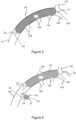
- Figure 1 illustrates a blood vessel occlusion balloon positioning arrangement 20 according to an embodiment of the present invention used in the pelvis area from the aorta 81.
- This can include, but is not limited to, targeting bladder, recto sigmoid, prostate, anal canal, vagina, cervix, uterus, ovary, lymphoma cytoma and sacral tumours.
- this region includes a number of blood vessels 23.
- the balloon positioning arrangement 20 includes an access device 41 for piercing and providing access to the blood vessels 23, a plurality of catheter lines 22 and catheter balloons 24 around the catheter lines 22 that are arranged to be inflated within a blood vessel to control the flow of blood to a target site.
- the target site is a tumour 11.
- the catheter lines 22 and balloons 24 are inserted into blood vessels via access device 41 and arranged in blood vessels 23 around the tumour 11 to isolate it from blood flow.
- the targeted organ/region in the pelvis area has a bilateral blood supply requiring control of the blood flow through both supplying blood vessels.
- This may require a co-rail system with two catheter lines 22 with separate balloons 24. This allows the two catheter lines 22 to place balloons 24 in both blood supply vessels.
- a balloon at the origin of the internal iliac system including both the anterior and posterior divisions with a super selective catheter going into the inferior vesical artery which is the desired optimal artery to infuse is used.
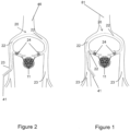
- FIG. 2 illustrates the use of the balloon positioning arrangement 20 used in blood vessels 23 from the inferior vena cava 46.
- the blood vessel occlusion balloon positioning arrangement 20 includes an access device 41 for piercing and providing access to the blood vessels 23, a plurality of catheter lines 22 and catheter balloons 24 around the catheter lines 22 that are arranged to be inflated within a vein to control the flow of blood to a target site.
- the target site is a tumour 11.
- the catheter lines 22 and balloons 24 are arranged in blood vessels 23 around the tumour 11 within the body to isolate it from blood flow.
- access device 41 can be used from the contralateral side or ipsilateral individually.
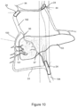
- Figure 3 shows an example of a blood flow control balloon 24 to minimise collateral venous flow and optimise infusion of chemotherapeutic agents in the right breast.
- Figure 4 shows an example of a plurality of blood flow balloons 24 being used to minimize collateral arterial flow and further optimise infusion of chemotherapeutic agents in the right breast.
- the balloons 24 co-operate to allow selective arterial infusion of chemotherapeutic or other therapeutic agents into a target area via an infusion channel 116 through catheter 22 and balloon 24 in the lateral thoracic artery 118.
- Collateral blood flow control balloon 114 minimizes arterial collateral flow to the target area by obstruction of the vessels distal to innominate artery 120, the internal thoracic artery 124, the superior thoracic artery 126 and the thyrocervical trunk 128.
- the common carotid artery 122 feeds into the innominate artery 120.
- irradiated particles can be injected to the region of the body to be isolated in the above description at the time of arterial infusion or at a later time.
- the region of the body can have some blood flow to the region at the time the irradiated particles are injected.
- collateral blood flow control balloon 24 minimizes venous collateral flow from the target area by obstruction of vessels proximal the innominate vein 130, the internal thoracic vein 134, the pectoral vein 136 and the lateral thoracic vein 138.
- there is obstruction of the axillary and subclavian arterial system to the right breast (as shown in Figure 4 )
- there is obstruction of the axillary and subclavian venous system from the right breast (as shown in Figure 3 ).
- the internal jugular vein 132 joins into the right subclavian vein 141.
- the obstruction of the main venous outflow from the right breast increases the venous pressure in the target area, thereby optimizing the effect of the chemotherapeutic agents on the lesion.
- Figure 3 also shows a shaft 140 that containing separate guidewire and inflation channels (not shown) leading to the balloon 24 via the basilic vein and then the right subclavian vein 141 , and an end 142 of the shaft 140.
- Figure 4 also shows a shaft 143 that contains separate guidewire and inflation channels (not shown) leading to the balloon 24 via the brachial artery or alternative access points as understood by the skilled addressee, and then the axillary artery. Also shown is a shaft 145 containing separate guidewire and inflation channels leading to the balloon 24, also via the brachia, artery and then the axillary artery 144, and an end 146 of the shaft 145.
- Figure 5 shows an arterial occlusion balloon positioning arrangement 20 of a balloon catheter system for vascular isolation of the liver 21.
- Three catheter balloons 24 on catheter lines 22 are inserted into the blood vessels 23 supplying blood to and from the liver 21.
- Balloons 24 are placed in a number of the superior mesenteric artery 25, the gastroduodenal artery 43, the common or proper hepatic artery 23, and the splenic artery 42.
- 46 is the inferior vena cava and 44 is the coeliac axis.
- Figure 6 shows an example of vascular isolation of the liver 21 to treat a tumour 11 by the positioning of an inflated occlusion balloon 24 in the hepatic artery 23 and by a microcatheter 3 that is located through a central guidewire channel of the occlusion balloon 24 and extends to an opening inside the hepatic artery 23.
- the microcatheter 3 is so formed that it wedges inside the vessels supplying the tumour 11 and, by the forcing of the walls of the microcatheter 3 against the walls of the vessels supplying the tumour, it obstructs flow through the arterial collaterals.
- the umbra or flow shadow is dense due to the double obstruction minimising the flow to the tumour 11.
- the portal collaterals are also obstructed by balloons 24 which are either intravascular or exovascular surrounding the celiac axis 44, superior mesenteric artery 25 and inferior mesenteric vessels, respectively.
- balloons 24 which are either intravascular or exovascular surrounding the celiac axis 44, superior mesenteric artery 25 and inferior mesenteric vessels, respectively.
- the result is a low arterial flow in the intestines 35 with secondary low flow through the portal vein 69 which further decreases the flow to the tumour 11.
- this flow can be further decreased by inflating an implantable cuff 26 around the portal vein 69.
- This method of vascular isolation also increases the ischemic effect, thereby inducing central necrosis in the tumour 11. which has a growing edge 5.
- the interstitial fluid flow in the lymphatics 4 from the tumour 11 is increased by increasing the pressure in the hepatic veins 73 and inferior vena cava (IVC) 46 through controlling the positive end expiratory pressures (PEEP).
- the outward flow from the tumour 11 can be controlled by varying the PEEP.
- three separate balloon 24 catheters 22 can be positioned to occlude the three hepatic veins 73, respectively.
- HABR hepatic artery buffer response
- Figure 7 shows an example applied to the vascular and arterial isolation of the cranial region 39. This may include tumours 37 of the brain or carcinoma of the tongue, larynx, pharynx, spacial skin and submandibular glands.
- the site of origin of the therapy is an access device 41 at the origin of the external carotid artery 74 or it can be from either or both groins or arms.
- the access device can be implanted unilaterally or bilaterally.
- Access device 41 is implanted bilaterally for structures receiving close to midline blood supply.
- the main axis is super selected to the target area and controlled with endovascular or extravascular balloon 24 occlusion systems on catheters 22 as described above.
- the occlusion system is related to the excellent collateral flow of a proximal and distal balloon 24 systems (co-rail systems are required to reduce pressures that correspond to the critical closing pressures which are 20mmHg at a pre capillary level).
- branches of the external carotid 74 may need to be cannulated depending on the radiological appearance and the pressures obtained after occluding the main axis.
- Other neighbouring branches of the external carotid may be required to be controlled including the branches of the subclavian vessels such as the costocervical and thyrocervical trunks.
- Outflow control is achieved by postural manoeuvres (such as moving into the Trendelenburg position), positive and expiratory pressures and occlusive catheters in the internal jugular vein 75, common facial or anterior jugular vein which may involve endovascular or external vessel occluding systems.
- Internal occlusion of the internal jugular vein is achieved with a balloon 24 catheter 22 as described above.
- External occlusion is achieved with an extravascular occlusion device 78 that applied pressure to the outside of a vein via an inflation line 79.
- the external occlusion with extravascular occlusion device 78 is applied to the same blood vessel that the access device is applied to, on the same side. That the occlusion device 78 is illustrated on the contralateral side in Figure 7 indicates that bilateral use.
- the venous pressures are continuously monitored. Once control of the vessels is contained, the plasma proteins and blood are washed out from the targeted segment and replaced with the saline containing therapeutic agents. With reestablishment of flow the collateral and main axis arterial inflow may be deflated first and the venous outflow control continues for 5-20 minutes to minimise systemic recirculation. With the plasma proteins washed out the action of the patient's antibodies is greatly reduced or eliminated. With the action of the patient's antibodies in the target segment being eliminated or reduced the chances of an immune response in the target segment is greatly reduced or removed.
- the blood brain barrier prevents more than 95% of therapeutic substances traversing the endothelium. Molecules less than 500 Daltons are usually able to cross. The problem is the tight junctions between endothelial cells do not allow free movement across this barrier.
- the next problem relates to the relative brain ischemia, particularly with focal infusions. The isolation treatment would best be done under local anaesthetic to modulate the infusion time.
- the last problem is the good collateral flow in some parts of the brain which is difficult to produce oncotic gradients as there is difficulty in washing out the oncotically active plasma proteins in the infused segments.
- the last problem relates to the difficulty of increasing the outflow pressure so that there is net movement from the intravascular to the extravascular space.
- inflow control is via arterial access via the groins external carotid artery 74 or the arm arteries. Collateral flow is minimised by the use of a collateral, so a co-rail system where one balloon is proximal in the larger vessel and the second one closer to the lesion usually in the same vessel, and infusion proceeds down the central or guidewire channel.
- Outflow cerebral hypertension can be improved by Trendelenburg or specific obstruction to the internal jugular vein either endovascularly, with occlusive balloon systems, or extravascular occluding system implanted around the internal jugular vein in the neck. This system can be activated and de-activated transcutaneously.
- the plasma proteins and blood are washed out from the segment and replaced by the active therapy. This may be aided by using hypertonic carrier solution to shrink the endothelial cells therefore increase the endothelial pore size. Another possibility is to use other carrier substance particularly if a lipophilic agents which traverse the blood brain barrier easier.
- Figures 8 and 9 illustrate methods and devices for vascular isolation applied to the lower limbs 82.
- Figure 8 illustrates arterial isolation
- Figure 9 illustrates venous isolation.
- the site of origin of endoluminal catheters may be on the contralateral limb in the common femoral or auxiliary or even brachial vessels or via an arteriovenous fistula. If the lymphatic systems cause occasion to be treated then controlling systems may position proximal to the lymphatic nodes i.e. the iliac systems. In some situations implantable extra vascular occlusive systems can be used.
- the site of origin of the therapy is an access device 41 at the origin of the common femoral artery 81 or it can be from either or both groins or arms.
- a balloon 24 is placed in the superficial femoral artery 83. In one embodiment, this is monitored by the appropriate pressure transduction. In the embodiment of Figure 9 a balloon 24 is placed in the superficial femoral vein. Outflow control can be aided by reverse Trendelenburg positioning. Endovascular balloons either ipsilateral or contralateral or tourniquets 42 may be appropriate in some cases and also positive and expiratory pressure can be added. Any or all of the above mechanisms may be used to control outflow.
- Figure 10 shows an arterial occlusion balloon positioning arrangement of three separate balloon 24 positions of the balloon positioning arrangement 20 for vascular isolation of the pancreas 53 through the anterior superior pancreaticoduodenal artery 193, is the anterior inferior pancreaticoduodenal artery 191 and the posterior superior pancreaticoduodenal artery 95. Also shown are the posterior inferior pancreaticoduodenal artery 97, the superior mesenteric artery 194 the gastroduodenal artery 192, the proper hepatic artery 94 and the coeliac axis 44.
- Figure 11 shows an example of an inflated mucosal compressive balloon 230 positioned in the duodenum 231 used in an example of the balloon positioning arrangement 20. Also shown is the superior pancreatic duodenal artery 232, its posterior branch 234, and its anterior branch 236. Also shown are the gastroduodenal arteries 238 and the pancreatic branches 240 from the anterior branch 236 of the superior pancreatic duodenal artery 232.
- Balloons 24 are positioned in the splenic origin 252, the superior pancreatic duodenal artery 232 and the superior mesenteric vessel 244, respectively.
- a pancreatic tumour 254 is shown in the head of the pancreas 256.
- the inflated mucosal compressive balloon 230 traverses all four portions of the duodenum 231.
- pancreas 256 As the pancreas 256 is now isolated, infusion of a chemotherapeutic agent to treat the targeted area (or tumour) can occur.
- the outer infusion balloon of the mucosal balloon 230 may be filled with ice water. Ice water has the effect of compressing of the blood vessels of the duodenum and has a secondary effect of prolonging ischemic time by minimising the effects of hypoxia, i.e. "cold ischemic time" is longer than "warm Ischemic time”. Cold temperature also produces vasoconstriction of the small blood vessels of the duodenum and this also protects against infusion of cytotoxic drugs. The blood vessels in the tumour 254, however, have little or no vasomotive tone owing to the absence of smooth muscle and nerves within the vessel walls.
- Varying the PEEP can increase the venous pressure in the liver and portal system so as to minimise leakage of the chemotherapeutic agent into the systemic circulation.
- direct balloon obstruction of the hepatic veins can increase venous pressure.
- tumour vessels do not react to cold in the way that other tissue does, the use of ice water allows targeting of tumour whilst avoiding delivery of therapeutic substances to the duodenum due to the mucosal tissues response to the ice water.
- FIG 11 A illustrates the mucosal balloon 230 in further detail.
- a multi-channel catheter 192 passes through the mucosal balloon 230.
- the mucosal balloon 230 includes an inner inflation balloon 194, adapted to be pressurised, and an outer infusion balloon 196 adapted to contain or transfer vasoconstrictive agents or cold fluid to surrounding tissue through elution ports 198.
- Temperature controlled fluid is injected into the inner balloon 194 through aperture 214 in a channel of catheter 192 and inflation fluid (such as air) is injected into inner balloon 194 through aperture 216 in a second channel of catheter 192 to inflate and maintain pressure in the inner balloon 194.
- Therapeutic substances are injected into the space between inner inflation balloon 194 and outer infusion balloon 196 through aperture 224 in a third channel of multi-catheter 192.
- the therapeutic substances are transferred through elution ports 198 into the surrounding tissue and the cold temperature assists the targeting of tissue such as tumour tissue.
- Figure 12 shows an arterial occlusion balloon positioning arrangement of three separate balloon catheter systems 75, 76, 77 to minimise collateral blood flow and optimise hyperperfusion in the liver.
- the balloon 78 of the system 75 which is a soft and malleable balloon, has a lumen 79.
- the balloon 78 extends longitudinally beyond the coeliac axis 80 into the aorta 81 and also stretches into the opening of the left gastric artery 82, the splenic artery 83 and the other collateral vessels of the common hepatic artery 84, such as the right gastric artery 85 and right gastroepiploic artery 86 and many small vessels.
- the balloon 87 of the system 76 is positioned in the left hepatic artery 88 and the balloon 89 of the system 77 is positioned in the right hepatic artery 90.
- the two separate catheters 91 , 92 for each balloon 87, 89 are capable of being passed through the internal diameter of the lumen 79 provided by the wider catheter 93 for the balloon 78.
- the balloon positioning arrangement shown in Figure 12 allows for optimal delivery of therapeutic agents by control of inflow from the common hepatic artery 84 and from collateral vessels.
- the balloon 78 when inflated , is at least 5 cm long but may be up to 40 cm long to occlude as many collateral vessels as possible. It is malleable to conform to the native vessel (i.e. the common hepatic artery 84) and to protrude partly into the openings of collateral vessels.
- the lumen 79 which also defines the central guidewire channel, has a larger diameter than guidewire channels of the prior art. As a result, the lumen 79 can act like a stabilising sheath. This will allow the balloon 78 and other such balloons to be used for isolation and occlusion of vessels which branch off very acutely from main vessels.
- a common method for inserting balloon catheter systems into acutely angled vessels involves a guidewire being initially inserted into the vessel and then a balloon catheter system being inserted over the guidewire to the desired position.
- the guidewire is removed in order to allow for inflation of the balloon and subsequent infusion of therapeutic agents, the uninflated balloon may slip out of the vessel.
- This problem may be avoided by use of the long collateral balloon 78 shown in Figure 12 in which the lumen 79 acts like a stabilising sheath, even when the balloon is uninflated.
- the guidewire can then be removed, and additional collateral balloon systems can then be inserted through the lumen of the long collateral balloon.
- the guidewire may be removed after the long collateral balloon is inflated.
- the balloon 78 is quite malleable and protrudes partly into the openings of collateral vessels, it produces greater frictional resistance forces so that, when the guidewire is removed, the inflated balloon does not slip out of the vessel.
- the lumen or central guidewire channel of most prior art balloon catheter systems are 0.889 mm or 0.965 mm (0.035 inches or 0.038 inches) in diameter.
- the balloon catheter system 75 employing the balloon 78 is capable of allowing two separate balloon infusion catheter systems to be passed through its lumen which each have a minimum diameter of 0.991 mm (0.039 inches).
- the balloon positioning arrangement shown in Figure 13 illustrates a mechanism of isolation and infusion of the right upper lobe of the lungs 100.
- the main branch 101 and the pulmonary vein 102 are shown.
- the skilled addressee will readily recognise that any part or the whole of either lung can be isolated in a similar manner.
- Non ventilation of a lung or segment leads to atelectasis or collapse of that lung or segment.
- Vasoconstriction of the pulmonary arteries follows physiologically in order to shunt blood to aerated segments.
- the blood flow of tumours are not as responsive to vasoconstriction related to their primitive nature hence the degree of vascular cell activity compared to normal tissue for selective infusion purposes.
- Some of the blood supply may come from brachial arteries which are less affected.
- the pulmonary venous pressure increases which may be aided by PEEP.
- the lungs are approximately 450g (right) and 400g (left); the right has 3 lobes. Projected mass ratio advantage in a 75kg patient who is approximately 600 times to a lobe. Collapse of the whole lung can be performed whilst infusion only of an affected segmental part as required by the anatomical distribution of the tumours.
- balloon positioning arrangement can also be used in the following applications.
- tumours of the nasal, pharynx and larynx may include tumours of the nasal, pharynx and larynx, the tongue, floor of mouth, sinuses, submandibular glands and malignant areas of the skin and mucous membrane.
- the usual site of origin of the therapy is a multi-access port at the origin of the external carotid or it can be from either or both groins or arms.
- Access device is implanted bilaterally for structures receiving close to midline blood supply.
- the main axis is superselected to the target area and controlled with endovascular or extravascular balloon occlusion systems and in some situations related to the excellent collateral flow a proximal and distal balloon systems (co-rail systems are required to reduce pressures that correspond to the critical closing pressures which are 20mmHg at a pre capillary level).
- branches of the external carotid may need to be cannulated depending on the radiological appearance and the pressures obtained after occluding the main axis.
- Other neighbouring branches of the external carotid may be required to be controlled including the branches of the subclavian vessels such as the costocervical and thyrocervical trunks.
- This may include lesions in the bladder, rectum, vagina, anal canal, prostate, uterus, cervix, lymphatics and other primary or secondary lesions.
- the site of origin of the catheters are the vascular access systems located in one or other or both groins may include the common femoral, superficial femoral systems and similarly the venous access system located in the common femoral, superficial femoral, external and iliac vein. Occasionally control of the great saphenous vein is required.
- the actual inflow may be controlled at two levels with superselection of the target organ e.g. the inferior vesical artery for prostate lesions with another balloon which controls the origin of the internal iliac system.
- synchronous control of the contralateral main axis with superselection can be achieved by guiding catheters placed retrograde over the bifurcation of the aorta.
- the pressures monitored are the superselected end pressures transduced on both sides individually and then together and similarly the collateral pressures again measured unilaterally then bilaterally.
- Outflow control is achieved by simultaneous occlusion of the internal, external or selected pelvic vein, iliac vein or veins. Elevation of the venous outflow pressure may be achieved by both postural manoeuvres (head up) and in addition to the positive and expiratory pressure (PEEP).
- PEEP positive and expiratory pressure
- the blood is removed from the isolated organ to be treated and replaced with the appropriate chemotherapeutic or other form of treatment in hypo-oncotic solution.
- the appropriate chemotherapeutic or other form of treatment in hypo-oncotic solution.
- the main axis arterial inflow is controlled by catheters and balloons in the common hepatic with superselection of the gastroduodenal or superior pancreaticoduodenal.
- Other lesions in the pancreas may require the splenic vessels or pancreatic magna to be the main axis control system and occasional superselection of the inferior pancreaticoduodenal is required.
- the collateral control is via balloon systems controlling the gastric the gastroepiploic, hepatic vessels and the splenic artery depending on the site of target tumour.
- PEEP positive and expiratory pressure
- the hepatic veins may also require control via balloons. This degree of occlusion controlled transcutaneously, radiologically. After vascular isolation the plasma proteins and blood are washed out from the isolated segment and replaced with saline containing the chemotherapeutic agent. Monitoring of the collateral as well as the main axial pressures and radiologically the placement of the appropriate catheters is mandatory.
- the access system is implanted in either arm in the brachial vessels or the groin.
- the internal mammary is superselected and occluded and prepared for infusion.
- the lateral thoracic vessel is superselected.
- the medial and lateral pectals can be isolated with 2 balloons proximal and distal to their origins.
- Collateral vessels, the other vessels that are not superselected i.e. the internal mammary, medial and lateral pectoral, thyrocervical trunk, costocervical trunk, and lateral thoracic vessels have occluded as required depending on the site of lesion.
- One single or two balloons are often sufficient to occlude all collateral inflow with appropriate pressure reduction.
- the outflow cannula's originate from the brachial and occlude all of the tributaries of the subclavian and axiliary vessels. Therefore the lateral thoracic vein, the medial and lateral pectoral veins, the veins from the thyrocervical and costcervical trunks and internal mammary vein are all occluded simultaneously. Any venous and arterial pressures are monitored both in the main axis and collateral pressures. The arterial systems are then occluded, the plasma proteins are then washed out and then the outflow balloons are inflated and the closed segment is replaced by saline containing the therapeutic agents.
- Site of origin of the catheters/balloons access system depends upon the site of the original lesion and associated lymphatic drainage and in some cases may originate in the groins.
- the inflow control system is placed on the proximal side i.e. the cardiac side of the lesion. This may include a double inclusion of the main axis or the use of a fistula to control inflow to the lesion.
- venous return axis Positive and expiratory pressure, posture and balloons placed on the cardiac side of the lesion as well as control of the appropriate tributaries to the main venous return axis.
- These vessels may be the brachial auxiliary or subclavian vessels.
- Resumption of circulation, venous outflow may be deflated several minutes after the inflow control system to minimise re-circulation of active therapeutic agents into unwanted areas.
- the cannulas, catheters and balloon of the above example can be inserted into the body through one access point into the inflow and outflow blood vessels as required. This reduces the number of access points required making extended use of the example in the body easier and reducing the injection points.
- an embodiment of the present invention relates to a blood vessel access device with a chamfered end to eliminate the creation of dead space when the cannula is inserted into a blood vessel.
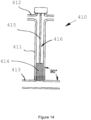
- FIGS 1 , 15 and 16 show prior art single lumen access devices.
- the access device 410 shown in Figure 14 has a cannula 411 with adaptor ports 412, and the cannula 411 is connected to a patient's blood vessel 413 at a perpendicular angle (90°).
- a tip 414 of a stem of a plunger 415 within the cannula 411 can be slid far enough towards a proximal end of the cannula so that the tip 414 reaches a point where the proximal end of the cannula is level with the wall of the blood vessel, thereby preventing the filling of the patient's blood into the cavity or lumen 416 of the cannula.
- the regular cylindrical shape of the tip 414 of the plunger may create a protrusion 418 into the lumen of the vessel (see Figure 15 ) or, if the tip 414 is retracted into the cannula to eliminate the protrusion, a dead space 419 is then created within the lumen of the cannula which will be filled with a small amount of blood (see Figure 16 ).
- Both the protrusion 418 and the dead space 419 can cause or contribute to haemodynamic disturbances or turbulence within the patient's circulatory system that may result in thrombotic events.
- the amount of dead space or protrusion when present, will vary according to the site of remote access, e.g. axillary, femoral, iliac, or jugular vessels.
- the plunger 420 shown in Figures 19 and 20 which is for use with the cannula 421 of the present invention shown in Figures 17 and 18 to form the single lumen access device, avoids this problem by having a chamfered tip 422 or proximal end configured such that the angle made between the plane of the chamfer of the tip 422 and the longitudinal axis of the plunger 420 is identical to the angle made between the longitudinal axis of the cannula 421 , through which the plunger stem travels, and the wall of the patient's vessel connected by the cannula 421.
- the plunger 420 acts to stop the flow of blood up the cannula 421. Blood flow up the cannula 421 can cause a thrombosis.
- the plunger 420 can include an internal lumen (not shown) running its entire length.
- the internal lumen can be plugged by a second plunger. The second plunger can removed to allow the provision of material through the internal lumen
- the cannula 421 has a proximal graft end 423 which has the same chamfered angle as that of the plunger tip 422 and a body portion 432 within which the plunger stem 424 sits.
- the plunger stem 424 is slid down the body portion 432 of the cannula 421 , the plane of the chamfer of the plunger tip 422 will be parallel with the patient's vessel wall 428, preventing dead space and thus reducing the likelihood of thrombotic events.
- the cannula 421 includes dacron cuffs along its length arranged to anchor the cannula 421 within the body.
- the inner walls 425 of the body portion 432 of the cannula 421 are so contoured as to mateably correspond with the contour of the outer walls 426 of the plunger stem 420, thereby enabling the plunger stem 424 to, during its passage through the cannula 421 , be guided in such a way that the chamfered surfaces of the proximal ends or tips 122. 123 of the plunger stem and cannula are correctly aligned.
- the alignment provided by the corresponding contoured walls 425, 426 mentioned above ensures that the chamfered surface of the plunger tip 422 will be parallel and in line with the vessel wall 428 so as to prevent any dead space within the lumen 427 of the cannula 421 or any protrusion into the vessel lumen. Haemodynamic disturbances that could result in thrombotic events will be prevented by this feature, and this will allow the access device to be used for a longer implant period without reducing its safety.
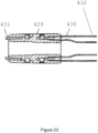
- Figure 22 shows a sectional view longitudinally of the cannula 421; whilst Figure 23 shows in sectional detail how a connector assembly 429 interconnects a proximal graft end portion 430 of the cannula 421 to an adjacent end portion 431 of a main body 432 of the cannula 421.
- Figure 24 shows in sectional detail how a connector assembly 433 is connected to a distal end portion 434 of the main body 432 of the cannula 421.
- the connector assembly 433 enables connection to a medical supply device such as a multiport adaptor, a pump, a drug supply, a radiation supply or otherwise.
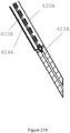
- second plunger stem 420A is used to stop the flow of blood up the lumen of the cannula 421 is used.
- the second plunger stem 420A includes passageway 422A along its length.
- the passageway 422A includes a one way valve 423A to allow injection of material into the cannula 421 whilst stopping fluid and particulates flowing into the passageway 422A from the cannula 421.
- the blood vessel access device with a chamfered end of Figures 14 to 24 provides an access device for the catheters 22 and balloons 24 for the isolation and therapeutic treatment of a region of the body or organ ad discussed above.
- an example relates to a multiport adaptor device for facilitating the insertion of multiple catheters into a single cannula lumen.
- the multiport adapter 235 shown in Figures 25 to 27 has a unitary end port 236 that is adapted to be connected onto the connector assembly 233 at the distal end portion 234 of the cannula 421 of Figures 17 to 24 .
- the adapter 235 has a branched portion 237 which diverges into three tubes, to each of which is releasably connected an item of external tubing 238, 239, 240 having respective outer ports 241 , 242, 243 that are designed to fit other medical devices with a male luer lock medical fitting of the type described in US 5,047,021 .
- connection means may be used to be used to connect the outer ports 241 ,242, 243 to other medical devices.
- Such medical devices may be haemostasis valves (see US 5,195,980 ; EP 0875262 ; US 6,22,1057 ), medical three-way stopcocks (see US 7,914,495 ), and syringes (see US 8,652,109 ).
- the adapter 235 can also receive catheters 44 and balloons 45 of three balloon catheter systems which all pass through the lumen of the cannula 421 and which are used in vascular isolation systems and to allow improved and enhanced communication with the patient's circulatory system.
- the multiport adaptor 225 includes four tubes 541 , 542, 543, 543 that are flexible and serve to act as a guide for the placement of catheters placed through the different tubes.
- the flexible tubes 541 , 542, 543, 544 allow independent steerage for the placement of the catheters through feeder connection port 545 where moving one flexible tube only affects one catheter without impacting other catheters.
- the tubes 541 , 542, 543, 544 have their distal ends connected to outer ports 546, 547, 548, 549.
- multiport adaptor includes more than three tubes.
- the plurality of tubes of the multiport adaptor are located within a unitary body to fix the location of the tubes with respect to each other.
- connection mechanism to a male luer lock can be used.
- the vascular isolation systems introduced into the patient's circulatory system are then used to control or even occlude the blood flow through the vessels 246 to and/or from an organ or a segment thereon.
- the adaptor 235 serves as an extracorporeal component of the access device. Where a plurality of smaller cannulas 44 are fed through the multiport adaptor 235 into the cannula 221 each of the smaller cannulas 44 can be directed to different positions to occlude or control the blood flow.
- Figures 28 to 30 show the implantable cannula 421 of Figures 17 to 24 connected at its distal end to the unitary end port 236 of a multiport adaptor 247 which is similar in structure and function to that shown in Figures 25 to 27 .
- Figure 30 shows the cannula 421 connected directly to the wall 228 of a patient's artery or vein.
- the multiport adaptor 247 also diverges to form a plurality of outer ports provided with ISO standard fluid/gas tight connections suitable for vascular applications.
- Three catheters 244 and balloons 245 all pass through the lumen of the implantable cannula 421 via the outer ports of the multiport adaptor 247, and the balloons 245 occlude blood flow through the vessels 246.
- the function of the multiport adaptor 235, 247 in facilitating the insertion of additional devices through the lumen of the implantable cannula 421 allows for multiple endovascular devices, such as catheters and balloons (hereinafter referred to as "balloon catheters", to be introduced simultaneously into the patient's vasculature via the implantable cannula. These endovascular devices can then be used simultaneously to administer treatments in a variety of ways.
- An example of a possible treatment involves the vascular isolation of organs or anatomical regions of the human body, including but not limited to the liver, pancreas or pelvic organs.
- multiple cannulation systems employing balloons and catheters are inserted into the patient's vasculature using the implantable cannula 421 and multiport adaptor 235, 247 and subsequently positioned in the arteries supplying blood to the target area or lesion.
- the balloons of these balloon catheter systems are then inflated, cutting off or occluding the arterial inflow to the target area and establishing an isolated zone of significantly reduced blood inflow. This isolated zone allows for infusion of therapeutic agents into the target area whilst minimizing systemic exposure.
- Vascular isolation may be further enhanced by using a separate access device to locate additional balloon catheter systems in the veins so as to occlude venous outflow from the target area or lesion, or by using positive end expiratory pressure (PEEP).
- PEEP positive end expiratory pressure
- external vascular fistula devices 300, 315, 320 are shown. These fistula devices 300, 315 320 allow repeated sterile access to the arterial and venous side of the circulation without interruption of the flow of blood through the fistula devices 300, 315, 320.
- the connector can be removed and replaced following arterial and venous control.
- the device allows sampling of blood without separate venous puncture. This capability improves the quality of life of cancer patients on chemotherapy who require a great deal of testing to particularly look at the haematological effects of the chemotherapy.
- the device allows catheter insertion for continuous remote intra-arterial or intravenous infusion for delivery of chemotherapy, stem cells or nano particles or antibiotics.
- the system may also have a catheter loop within itself for example for real time recognition of cell type.
- a catheter is inserted into the arterial side of the fistula devices 300, 315, 320 and this traverses a device which immediately recognises cell type in real time and then delivers the blood back into the venous system without interruption of fistula flow.
- a similar system is extraction via the venous part of the fistula devices 300, 315, 320 and re-insertion via a pump into the arterial system; this is known as remote closed loop recirculation. This is appropriate in some forms of chemotherapy, particularly if detoxification is required.
- the device is also appropriate for repetitive diagnostic angiography by insertion of a catheter into the arterial venous side as required.
- the device construction addresses safety issues with essentially minimal chance of spontaneous dislocation and tampering.
- the fistula device 300, 315, 320 is compatible with both of the arterial and venous vascular tube and therefore allows the access to be continued by plugging the tube with a plunger i.e. if necessary the access device can be removed and replaced by plungers in either or both access tubes.
- a previous single intra-arterial device can be converted into a fistula device 300, 315, 320 if the access to the other side of the circulation is required.
- the external fistula device 301 includes a bridging device 307 designed to connect to arterial cannula 303 and venous cannula 305.
- the bridging device 307 acts to provide a passageway 310 between the arterial cannula 303 and venous cannula 305 to allow blood to flow through.
- the bridging device 307 includes engagement means 309 to fix the bridging device 307 to the arterial and venous cannulas 303, 305.
- the engagement means 309 can be in the form of a screw thread, a clip, a snap fit or otherwise and understood by the skilled addressee.
- the passageway 210 of the bridging device 307 sealingly engages with the passageways of the arterial and venous cannulas 303, 305 at engagement point 311.
- Engagement point 311 includes a seal to stop leakage of blood passing into or from the bridging device.
- An access portal 301 is located on the bridging device 307 to provide access to the arterial and venous cannulas 303, 305.
- the access portal 301 feeds directly into the passageway 210 allowing catheters to be fed into either or both of the arterial side or venous side of the fistula connection. This arrangement allows for repeated catheterisation through access portal without needing to compromise the connection between the arterial and venous cannulas.
- an alternative external fistula device 315 is shown connected to arterial cannula 303 and venous cannula 305.
- a bridging device 313 with passageway 310 is used to connect the arterial and venous cannulas 303,305 together.
- Connection devices 319 sealingly fix the bridging device 313 to the arterial and venous cannulas 303, 305.
- the bridging device includes both arterial side access portal 317 and a venous side access portal 318.
- Arterial access portal 317 is used to insert catheters through the arterial cannula 303 into an artery.
- Venous access portal 318 is used to insert a catheter through the venous cannula 305 into a vein. Seals at the top of arterial access portal 317 and venous access portal 318 allow repeated catheterisation through the bridging device without needing to puncture arteries or veins.
- Figure 33 illustrates the arterial access portal 317 of Figure 32 .
- a catheter is inserted through seal 323 through passageway 321 into arterial cannula 303.
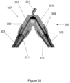
- FIG 34 illustrates an alternative external fistula device 320.
- connection means 327 fix the external fistula device 320 to the arterial and venous cannulas 303, 305.
- Arterial access portal 322 includes a seal and is arranged to receive a catheter for insertion to an artery.
- Venous access portal 324 includes a seal and is arranged to receive a catheter for insertion to a vein.
- the connection means can be in the form of a threaded screw mean, a clip, a clamp or otherwise as understood by the skilled addressee.
- the arterial and venous access portals 322, 324 are arranged for repeated use so that catheters can be easily inserted and removed.
- the T arterial and venous access portals 322, 324 include a pierceable membrane.
- the external fistula device is flexible.
- the alternative external fistula device 320 of Figure 34 is shown with catheters inserted into an artery and vein via the arterial and venous access portals 322, 324.
- Figure 36 illustrates a scenario where the alternative external fistula device 320 has been removed from the connection between arterial and venous cannulas 303, 305 leading into artery 333 and vein 335.
- a plunger 337 is placed through connection means 327 into venous cannula 305 to plug the venous blood.
- Multiport adaptor 35 is connected to arterial cannula 303 to allow insertion of catheters 44 and balloons 45. This allows for the occlusion of arteries and the isolation of organs to use the method discussed above for therapeutic treatment.
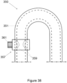
- the external fistula device 350 includes an internal tube 351.
- a first constriction device 353 engages the outer housing 354 of the external fistula device 350.
- a constriction control element 355 passes into the external fistula device and engages the internal tube 351.
- the constriction device applies force to the inner tube and constricts a reduced diameter portion 356 of the internal tube 351.
- the constriction device 353 can apply side to side constriction of the internal tube 351.
- the constriction device 353 can apply circumferential constriction to the internal tube.
- the constriction device 353 can apply with a screw, hydraulic, pneumatic means or otherwise as understood by the skilled addressee.
- a second constriction device 357 is placed around the outer housing 354 of the external fistula device 350.
- the second constriction device 357 constricts both the outer housing 354 and the internal tube 351 at constricted region 359 of the external fistula device 350.
- the constriction can be either side to side or circumferential and is controlled by control element 361 which is a screw, hydraulic, pneumatic means or otherwise as understood by the skilled addressee.
- constricted internal tube 351 allows control of the flow rate of fluid through the fistula.
Landscapes
- Health & Medical Sciences (AREA)
- Heart & Thoracic Surgery (AREA)
- Life Sciences & Earth Sciences (AREA)
- Vascular Medicine (AREA)
- General Health & Medical Sciences (AREA)
- Biomedical Technology (AREA)
- Hematology (AREA)
- Engineering & Computer Science (AREA)
- Animal Behavior & Ethology (AREA)
- Public Health (AREA)
- Veterinary Medicine (AREA)
- Anesthesiology (AREA)
- Cardiology (AREA)
- Pulmonology (AREA)
- Oncology (AREA)
- Biophysics (AREA)
- Child & Adolescent Psychology (AREA)
- Infusion, Injection, And Reservoir Apparatuses (AREA)
- External Artificial Organs (AREA)
- Medicines That Contain Protein Lipid Enzymes And Other Medicines (AREA)
- Acyclic And Carbocyclic Compounds In Medicinal Compositions (AREA)
- Peptides Or Proteins (AREA)
Claims (9)
- Gefäßzugangsvorrichtung zum Bereitstellen eines verlängerten Gefäßzugangs für die Infusion von therapeutischen Mitteln und/oder für die Einführung einer oder mehrerer endovaskulärer Vorrichtungen, umfassend:eine abgeschrägte Kanüle (421), die ein abgeschrägtes Kanülenende beinhaltet, das so angeordnet ist, dass es in ein Blutgefäß (413) in einem Winkel zur Verbindung mit dem Blutgefäß eingreift,sodass ein Lumen (427) der Kanüle in Fluidverbindung mit dem Blutgefäß (413) verbunden ist; undeinen entfernbaren Kolben (420), der so konfiguriert ist, dass er in das Lumen (427) der Kanüle (421) eingeführt und so angeordnet ist, dass er das Lumen (427) der Kanüle blockiert und abdichtet;wobei der entfernbare Kolben ein abgeschrägtes Ende (422) beinhaltet, das so angeordnet ist, dass Totraum (419) innerhalb des Endes der Kanüle beseitigt wird, wenn der Kolben (420) vollständig in die Kanüle (421) eingeführt ist, um das Lumen (427) der Kanüle zu blockieren und abzudichten; undwobei das abgeschrägte Ende (422) des entfernbaren Kolbens (420) so angeordnet ist, dass es nicht in das Blutgefäß (413) vorsteht, wenn der Kolben vollständig in das Lumen (427) der Kanüle eingeführt ist, um die Kanüle zu blockieren und abzudichten.
- Gefäßzugangsvorrichtung nach Anspruch 1, wobei das abgeschrägte Kanülenende und das abgeschrägte Ende (422) des Kolbens den gleichen abgeschrägten Winkel aufweisen.
- Gefäßzugangsvorrichtung nach Anspruch 1, wobei eine Innenwand (425) der Kanüle (421), die das Lumen (427) definiert, so profiliert ist, dass sie passend einer Außenwand (426) des Kolbens (420) entspricht.
- Gefäßzugangsvorrichtung nach Anspruch 3, wobei die Innenwand (425) der Kanüle so profiliert ist, dass sich der Kolben (420) aufgrund der passenden Entsprechung mit der Außenwand (426) des Kolbens nicht drehen kann.
- Gefäßzugangsvorrichtung nach Anspruch 3 oder Anspruch 4, wobei ein oder mehrere Vorsprünge der Außenwand (426) des Kolbens (420) so angeordnet sind, dass sie in entsprechenden Ausnehmungen in der Innenwand (425) der Kanüle (421) aufgenommen werden können.
- Gefäßzugangsvorrichtung nach einem der Ansprüche 3 bis 5, wobei die passende Entsprechung der Kanüleninnenwand (425) und der Kolbenaußenwand (426) so angeordnet ist, dass das abgeschrägte Kanülenende parallel zu dem abgeschrägten Ende (422) des Kolbens ist und mit diesem ausgerichtet ist, wenn der Kolben (420) vollständig in die Kanüle (421) eingeführt ist.
- Gefäßzugangsvorrichtung nach einem der Ansprüche 1 bis 6, wobei das abgeschrägte Kanülenende als ein Transplantatende (423) konfiguriert und angeordnet ist, um über ein Gefäßtransplantat in das Blutgefäß (413) einzugreifen und sich mit diesem zu verbinden.
- Gefäßzugangsvorrichtung nach Anspruch 7, wobei die Kanüle (421) eine Verbindungsanordnung (429; 433) distal zu dem Transplantatende (423) beinhaltet, die so angeordnet ist, dass sie mit einer medizinischen Versorgungsvorrichtung verbunden ist.
- Gefäßzugangsvorrichtung nach Anspruch 8, wobei die Verbindungsanordnung (429; 433) so angeordnet ist, dass sie mit einem Körperabschnitt (432) der Kanüle (421) verbunden ist.
Applications Claiming Priority (6)
| Application Number | Priority Date | Filing Date | Title |
|---|---|---|---|
| AU2016903834A AU2016903834A0 (en) | 2016-09-22 | Chamfered cannula | |
| AU2016903836A AU2016903836A0 (en) | 2016-09-22 | Multiport access | |
| AU2016904991A AU2016904991A0 (en) | 2016-12-05 | Devices and methods for vascular isolation of organs | |
| AU2016905067A AU2016905067A0 (en) | 2016-12-08 | Chamfered cannula | |
| AU2016905068A AU2016905068A0 (en) | 2016-12-08 | Multiport access | |
| PCT/AU2017/050266 WO2018053574A1 (en) | 2016-09-22 | 2017-03-24 | Devices and methods for vascular hyperperfusion of extravascular space |
Publications (4)
| Publication Number | Publication Date |
|---|---|
| EP3515520A1 EP3515520A1 (de) | 2019-07-31 |
| EP3515520A4 EP3515520A4 (de) | 2020-10-07 |
| EP3515520B1 true EP3515520B1 (de) | 2024-03-06 |
| EP3515520C0 EP3515520C0 (de) | 2024-03-06 |
Family
ID=61689264
Family Applications (1)
| Application Number | Title | Priority Date | Filing Date |
|---|---|---|---|
| EP17851976.5A Active EP3515520B1 (de) | 2016-09-22 | 2017-03-24 | Vorrichtungen und verfahren zur vaskulären hyperperfusion des extravaskulären raums |
Country Status (10)
| Country | Link |
|---|---|
| US (1) | US11464892B2 (de) |
| EP (1) | EP3515520B1 (de) |
| JP (3) | JP2019528943A (de) |
| CN (1) | CN110300607A (de) |
| AU (1) | AU2017331801B2 (de) |
| BR (1) | BR112019005553A2 (de) |
| ES (1) | ES2979040T3 (de) |
| IL (1) | IL265532B2 (de) |
| NZ (1) | NZ752760A (de) |
| WO (1) | WO2018053574A1 (de) |
Families Citing this family (5)
| Publication number | Priority date | Publication date | Assignee | Title |
|---|---|---|---|---|
| CN109045453B (zh) * | 2018-10-13 | 2020-11-03 | 郭锐 | 妇科用阴部涂药器 |
| US12433598B2 (en) * | 2020-10-13 | 2025-10-07 | Asahi Intecc Co., Ltd. | Thrombus aspiration systems and related methods |
| US12011173B2 (en) * | 2020-12-30 | 2024-06-18 | Kar Health, LLC | Dual balloon catheter and related methods for treatment of heart failure |
| CN114432576B (zh) * | 2022-01-04 | 2023-07-07 | 吉林大学 | 一种用于尸体靶向心脑血管造影装置及方法 |
| CN114631875B (zh) * | 2022-05-17 | 2022-07-26 | 首都医科大学附属北京安贞医院 | 一种用于心脏房间隔穿刺的装置 |
Family Cites Families (28)
| Publication number | Priority date | Publication date | Assignee | Title |
|---|---|---|---|---|
| US2547099A (en) * | 1948-03-11 | 1951-04-03 | Becton Dickinson Co | Injection device and ampoule |
| US3585986A (en) * | 1969-08-21 | 1971-06-22 | Becton Dickinson Co | Stylet |
| US3853126A (en) * | 1973-11-15 | 1974-12-10 | Heyer Schulte Corp | Artery-to-vein shunt |
| US4133312A (en) * | 1976-10-13 | 1979-01-09 | Cordis Dow Corp. | Connector for attachment of blood tubing to external arteriovenous shunts and fistulas |
| US4318401A (en) * | 1980-04-24 | 1982-03-09 | President And Fellows Of Harvard College | Percutaneous vascular access portal and catheter |
| US4701159A (en) | 1984-12-05 | 1987-10-20 | I-Flow Corporation | Multilumen catheter set |
| US5047021A (en) | 1989-08-29 | 1991-09-10 | Utterberg David S | Male luer lock medical fitting |
| US5195980A (en) | 1992-01-03 | 1993-03-23 | Thomas Medical Products, Inc. | Hemostatic valve |
| NL9200581A (nl) * | 1992-03-30 | 1993-10-18 | Akuaba B V | Implantatie-inrichting. |
| JP3614943B2 (ja) * | 1994-09-29 | 2005-01-26 | オリンパス株式会社 | 内視鏡用穿刺針 |
| US6217561B1 (en) | 1995-06-06 | 2001-04-17 | David Gibbs | Medication injection device and method |
| US5814017A (en) * | 1996-07-18 | 1998-09-29 | Safegard Medical Products, Inc. | Single use syringe device |
| US5895376A (en) | 1996-10-23 | 1999-04-20 | Mayo Foundation For Medical Education And Research | Hemostasis valve, system and assembly |
| US6827710B1 (en) | 1996-11-26 | 2004-12-07 | Edwards Lifesciences Corporation | Multiple lumen access device |
| US5911710A (en) | 1997-05-02 | 1999-06-15 | Schneider/Namic | Medical insertion device with hemostatic valve |
| US6699231B1 (en) * | 1997-12-31 | 2004-03-02 | Heartport, Inc. | Methods and apparatus for perfusion of isolated tissue structure |
| SE516215C2 (sv) * | 1999-07-10 | 2001-12-03 | Argmed Kb | Perfusionssystem samt pumpanordning och styrsystem för användning i perfusionssystemet |
| US6592544B1 (en) | 1999-11-24 | 2003-07-15 | Edwards Lifesciences Corporation | Vascular access devices having hemostatic safety valve |
| ES1056051Y (es) | 2003-11-12 | 2004-06-01 | Amor Vicente Gomez | Valvula de tres vias perfeccionada. |
| ES2458365T3 (es) | 2004-09-07 | 2014-05-05 | Droneon Pty Limited | Dispositivos y sistemas de acceso periférico |
| JP2008521575A (ja) * | 2004-12-01 | 2008-06-26 | ジェンザイム・コーポレイション | 肝臓を標的とした遺伝物質の送達方法 |
| JP2009034462A (ja) * | 2007-07-31 | 2009-02-19 | Koosei Advance:Kk | 膵臓治療用灌流システム |
| CA2705073C (en) | 2007-11-07 | 2016-12-06 | Rodney James Lane | Systems, methods and devices for circulatory access |
| ITTO20070141U1 (it) | 2007-11-14 | 2009-05-15 | Borla Ind | Siringa |
| WO2009136871A1 (en) * | 2008-05-06 | 2009-11-12 | National University Of Singapore | An improved cannula adaptor |
| CN102271747B (zh) * | 2008-11-03 | 2014-06-04 | 先端导管治疗公司 | 闭塞灌流导管 |
| US9308310B2 (en) * | 2010-02-02 | 2016-04-12 | Nirva Medical, Llc | Localized therapy delivery and local organ protection |
| CN203138632U (zh) * | 2013-03-15 | 2013-08-21 | 青岛市市立医院 | 心血管介入治疗用穿刺针 |
-
2017
- 2017-03-24 JP JP2019516392A patent/JP2019528943A/ja active Pending
- 2017-03-24 AU AU2017331801A patent/AU2017331801B2/en active Active
- 2017-03-24 US US16/335,603 patent/US11464892B2/en active Active
- 2017-03-24 BR BR112019005553A patent/BR112019005553A2/pt not_active Application Discontinuation
- 2017-03-24 EP EP17851976.5A patent/EP3515520B1/de active Active
- 2017-03-24 ES ES17851976T patent/ES2979040T3/es active Active
- 2017-03-24 WO PCT/AU2017/050266 patent/WO2018053574A1/en not_active Ceased
- 2017-03-24 NZ NZ752760A patent/NZ752760A/en not_active IP Right Cessation
- 2017-03-24 CN CN201780072251.2A patent/CN110300607A/zh active Pending
-
2019
- 2019-03-21 IL IL265532A patent/IL265532B2/en unknown
-
2021
- 2021-08-24 JP JP2021136214A patent/JP7679598B2/ja active Active
-
2022
- 2022-02-14 JP JP2022020286A patent/JP2022081487A/ja active Pending
Also Published As
| Publication number | Publication date |
|---|---|
| NZ752760A (en) | 2022-05-27 |
| ES2979040T3 (es) | 2024-09-24 |
| EP3515520A4 (de) | 2020-10-07 |
| IL265532B1 (en) | 2023-01-01 |
| IL265532B2 (en) | 2023-05-01 |
| IL265532A (en) | 2019-05-30 |
| AU2017331801B2 (en) | 2022-04-21 |
| JP2022008302A (ja) | 2022-01-13 |
| EP3515520C0 (de) | 2024-03-06 |
| WO2018053574A1 (en) | 2018-03-29 |
| JP2022081487A (ja) | 2022-05-31 |
| US20200038575A1 (en) | 2020-02-06 |
| EP3515520A1 (de) | 2019-07-31 |
| BR112019005553A2 (pt) | 2019-06-11 |
| JP7679598B2 (ja) | 2025-05-20 |
| AU2017331801A1 (en) | 2019-05-16 |
| JP2019528943A (ja) | 2019-10-17 |
| US11464892B2 (en) | 2022-10-11 |
| CN110300607A (zh) | 2019-10-01 |
Similar Documents
| Publication | Publication Date | Title |
|---|---|---|
| JP7679598B2 (ja) | 血管外空間の血管過灌流のための装置及び方法 | |
| US6086553A (en) | Arteriovenous shunt | |
| US20110257577A1 (en) | Systems, methods and devices for circulatory access | |
| US5562617A (en) | Implantable vascular device | |
| US7223257B2 (en) | Percutaneous vascular access device | |
| CA2874661C (en) | Control catheters and methods for pulmonary suffusion and related therapies | |
| US20040210236A1 (en) | Flow path control catheter with funnel-shaped expandable structure at proximal part and tubular-shaped structure at distal part and perfusion system with such a catheter | |
| EP1202759B1 (de) | Perfusionsanordnung | |
| WO2019027380A1 (en) | INJECTION METHOD AND EXPANSION DEVICE FOR THE DESIRED PRESSURE AND CONTENT OF A LIQUID AND / OR MEDICINAL PRODUCT IN THE VEIN WITH A BALLOON CATHETER | |
| JP2009034462A (ja) | 膵臓治療用灌流システム | |
| KR101671612B1 (ko) | 장기 적출 수술용 복강 내 장기관류장치 | |
| NZ786483A (en) | Devices and methods for vascular hyperperfusion of the extravascular space | |
| NZ786486A (en) | Devices and methods for vascular hyperperfusion of the extravascular space | |
| US20210205523A1 (en) | Catheter Clearance Device and Method of Use | |
| HK40015175A (en) | Devices and methods for vascular hyperperfusion of extravascular space | |
| WO2000029046A2 (en) | Perfusion system | |
| McDermott et al. | An isolated limb infusion technique: a guide for the perfusionist | |
| JPS62155861A (ja) | 治療装置 | |
| US20220401703A1 (en) | Vascular Access Systems and Methods Thereof |
Legal Events
| Date | Code | Title | Description |
|---|---|---|---|
| STAA | Information on the status of an ep patent application or granted ep patent |
Free format text: STATUS: THE INTERNATIONAL PUBLICATION HAS BEEN MADE |
|
| PUAI | Public reference made under article 153(3) epc to a published international application that has entered the european phase |
Free format text: ORIGINAL CODE: 0009012 |
|
| STAA | Information on the status of an ep patent application or granted ep patent |
Free format text: STATUS: REQUEST FOR EXAMINATION WAS MADE |
|
| 17P | Request for examination filed |
Effective date: 20190418 |
|
| AK | Designated contracting states |
Kind code of ref document: A1 Designated state(s): AL AT BE BG CH CY CZ DE DK EE ES FI FR GB GR HR HU IE IS IT LI LT LU LV MC MK MT NL NO PL PT RO RS SE SI SK SM TR |
|
| AX | Request for extension of the european patent |
Extension state: BA ME |
|
| DAV | Request for validation of the european patent (deleted) | ||
| DAX | Request for extension of the european patent (deleted) | ||
| RIC1 | Information provided on ipc code assigned before grant |
Ipc: A61M 1/00 20060101AFI20200513BHEP Ipc: A61M 39/00 20060101ALI20200513BHEP |
|
| A4 | Supplementary search report drawn up and despatched |
Effective date: 20200909 |
|
| RIC1 | Information provided on ipc code assigned before grant |
Ipc: A61M 1/00 20060101AFI20200903BHEP Ipc: A61M 39/00 20060101ALI20200903BHEP |
|
| GRAP | Despatch of communication of intention to grant a patent |
Free format text: ORIGINAL CODE: EPIDOSNIGR1 |
|
| STAA | Information on the status of an ep patent application or granted ep patent |
Free format text: STATUS: GRANT OF PATENT IS INTENDED |
|
| INTG | Intention to grant announced |
Effective date: 20230421 |
|
| GRAJ | Information related to disapproval of communication of intention to grant by the applicant or resumption of examination proceedings by the epo deleted |
Free format text: ORIGINAL CODE: EPIDOSDIGR1 |
|
| STAA | Information on the status of an ep patent application or granted ep patent |
Free format text: STATUS: REQUEST FOR EXAMINATION WAS MADE |
|
| INTC | Intention to grant announced (deleted) | ||
| GRAP | Despatch of communication of intention to grant a patent |
Free format text: ORIGINAL CODE: EPIDOSNIGR1 |
|
| STAA | Information on the status of an ep patent application or granted ep patent |
Free format text: STATUS: GRANT OF PATENT IS INTENDED |
|
| INTG | Intention to grant announced |
Effective date: 20231004 |
|
| GRAS | Grant fee paid |
Free format text: ORIGINAL CODE: EPIDOSNIGR3 |
|
| GRAA | (expected) grant |
Free format text: ORIGINAL CODE: 0009210 |
|
| STAA | Information on the status of an ep patent application or granted ep patent |
Free format text: STATUS: THE PATENT HAS BEEN GRANTED |
|
| AK | Designated contracting states |
Kind code of ref document: B1 Designated state(s): AL AT BE BG CH CY CZ DE DK EE ES FI FR GB GR HR HU IE IS IT LI LT LU LV MC MK MT NL NO PL PT RO RS SE SI SK SM TR |
|
| REG | Reference to a national code |
Ref country code: GB Ref legal event code: FG4D |
|
| REG | Reference to a national code |
Ref country code: CH Ref legal event code: EP |
|
| REG | Reference to a national code |
Ref country code: IE Ref legal event code: FG4D |
|
| REG | Reference to a national code |
Ref country code: DE Ref legal event code: R096 Ref document number: 602017079845 Country of ref document: DE |
|
| U01 | Request for unitary effect filed |
Effective date: 20240405 |
|
| U07 | Unitary effect registered |
Designated state(s): AT BE BG DE DK EE FI FR IT LT LU LV MT NL PT SE SI Effective date: 20240415 |
|
| U20 | Renewal fee for the european patent with unitary effect paid |
Year of fee payment: 8 Effective date: 20240415 |
|
| PG25 | Lapsed in a contracting state [announced via postgrant information from national office to epo] |
Ref country code: GR Free format text: LAPSE BECAUSE OF FAILURE TO SUBMIT A TRANSLATION OF THE DESCRIPTION OR TO PAY THE FEE WITHIN THE PRESCRIBED TIME-LIMIT Effective date: 20240607 |
|
| PG25 | Lapsed in a contracting state [announced via postgrant information from national office to epo] |
Ref country code: RS Free format text: LAPSE BECAUSE OF FAILURE TO SUBMIT A TRANSLATION OF THE DESCRIPTION OR TO PAY THE FEE WITHIN THE PRESCRIBED TIME-LIMIT Effective date: 20240606 Ref country code: HR Free format text: LAPSE BECAUSE OF FAILURE TO SUBMIT A TRANSLATION OF THE DESCRIPTION OR TO PAY THE FEE WITHIN THE PRESCRIBED TIME-LIMIT Effective date: 20240306 |
|
| PG25 | Lapsed in a contracting state [announced via postgrant information from national office to epo] |
Ref country code: RS Free format text: LAPSE BECAUSE OF FAILURE TO SUBMIT A TRANSLATION OF THE DESCRIPTION OR TO PAY THE FEE WITHIN THE PRESCRIBED TIME-LIMIT Effective date: 20240606 Ref country code: NO Free format text: LAPSE BECAUSE OF FAILURE TO SUBMIT A TRANSLATION OF THE DESCRIPTION OR TO PAY THE FEE WITHIN THE PRESCRIBED TIME-LIMIT Effective date: 20240606 Ref country code: HR Free format text: LAPSE BECAUSE OF FAILURE TO SUBMIT A TRANSLATION OF THE DESCRIPTION OR TO PAY THE FEE WITHIN THE PRESCRIBED TIME-LIMIT Effective date: 20240306 Ref country code: GR Free format text: LAPSE BECAUSE OF FAILURE TO SUBMIT A TRANSLATION OF THE DESCRIPTION OR TO PAY THE FEE WITHIN THE PRESCRIBED TIME-LIMIT Effective date: 20240607 |
|
| REG | Reference to a national code |
Ref country code: ES Ref legal event code: FG2A Ref document number: 2979040 Country of ref document: ES Kind code of ref document: T3 Effective date: 20240924 |
|
| PG25 | Lapsed in a contracting state [announced via postgrant information from national office to epo] |
Ref country code: IS Free format text: LAPSE BECAUSE OF FAILURE TO SUBMIT A TRANSLATION OF THE DESCRIPTION OR TO PAY THE FEE WITHIN THE PRESCRIBED TIME-LIMIT Effective date: 20240706 |
|
| PG25 | Lapsed in a contracting state [announced via postgrant information from national office to epo] |
Ref country code: SM Free format text: LAPSE BECAUSE OF FAILURE TO SUBMIT A TRANSLATION OF THE DESCRIPTION OR TO PAY THE FEE WITHIN THE PRESCRIBED TIME-LIMIT Effective date: 20240306 |
|
| PG25 | Lapsed in a contracting state [announced via postgrant information from national office to epo] |
Ref country code: CZ Free format text: LAPSE BECAUSE OF FAILURE TO SUBMIT A TRANSLATION OF THE DESCRIPTION OR TO PAY THE FEE WITHIN THE PRESCRIBED TIME-LIMIT Effective date: 20240306 |
|
| PG25 | Lapsed in a contracting state [announced via postgrant information from national office to epo] |
Ref country code: PL Free format text: LAPSE BECAUSE OF FAILURE TO SUBMIT A TRANSLATION OF THE DESCRIPTION OR TO PAY THE FEE WITHIN THE PRESCRIBED TIME-LIMIT Effective date: 20240306 |
|
| PG25 | Lapsed in a contracting state [announced via postgrant information from national office to epo] |
Ref country code: SK Free format text: LAPSE BECAUSE OF FAILURE TO SUBMIT A TRANSLATION OF THE DESCRIPTION OR TO PAY THE FEE WITHIN THE PRESCRIBED TIME-LIMIT Effective date: 20240306 |
|
| PG25 | Lapsed in a contracting state [announced via postgrant information from national office to epo] |
Ref country code: SM Free format text: LAPSE BECAUSE OF FAILURE TO SUBMIT A TRANSLATION OF THE DESCRIPTION OR TO PAY THE FEE WITHIN THE PRESCRIBED TIME-LIMIT Effective date: 20240306 Ref country code: SK Free format text: LAPSE BECAUSE OF FAILURE TO SUBMIT A TRANSLATION OF THE DESCRIPTION OR TO PAY THE FEE WITHIN THE PRESCRIBED TIME-LIMIT Effective date: 20240306 Ref country code: RO Free format text: LAPSE BECAUSE OF FAILURE TO SUBMIT A TRANSLATION OF THE DESCRIPTION OR TO PAY THE FEE WITHIN THE PRESCRIBED TIME-LIMIT Effective date: 20240306 Ref country code: PL Free format text: LAPSE BECAUSE OF FAILURE TO SUBMIT A TRANSLATION OF THE DESCRIPTION OR TO PAY THE FEE WITHIN THE PRESCRIBED TIME-LIMIT Effective date: 20240306 Ref country code: IS Free format text: LAPSE BECAUSE OF FAILURE TO SUBMIT A TRANSLATION OF THE DESCRIPTION OR TO PAY THE FEE WITHIN THE PRESCRIBED TIME-LIMIT Effective date: 20240706 Ref country code: CZ Free format text: LAPSE BECAUSE OF FAILURE TO SUBMIT A TRANSLATION OF THE DESCRIPTION OR TO PAY THE FEE WITHIN THE PRESCRIBED TIME-LIMIT Effective date: 20240306 |
|
| REG | Reference to a national code |
Ref country code: CH Ref legal event code: PL |
|
| REG | Reference to a national code |
Ref country code: DE Ref legal event code: R097 Ref document number: 602017079845 Country of ref document: DE |
|
| PG25 | Lapsed in a contracting state [announced via postgrant information from national office to epo] |
Ref country code: MC Free format text: LAPSE BECAUSE OF FAILURE TO SUBMIT A TRANSLATION OF THE DESCRIPTION OR TO PAY THE FEE WITHIN THE PRESCRIBED TIME-LIMIT Effective date: 20240306 |
|
| PLBE | No opposition filed within time limit |
Free format text: ORIGINAL CODE: 0009261 |
|
| STAA | Information on the status of an ep patent application or granted ep patent |
Free format text: STATUS: NO OPPOSITION FILED WITHIN TIME LIMIT |
|
| PG25 | Lapsed in a contracting state [announced via postgrant information from national office to epo] |
Ref country code: IE Free format text: LAPSE BECAUSE OF NON-PAYMENT OF DUE FEES Effective date: 20240324 |
|
| PG25 | Lapsed in a contracting state [announced via postgrant information from national office to epo] |
Ref country code: MC Free format text: LAPSE BECAUSE OF FAILURE TO SUBMIT A TRANSLATION OF THE DESCRIPTION OR TO PAY THE FEE WITHIN THE PRESCRIBED TIME-LIMIT Effective date: 20240306 Ref country code: IE Free format text: LAPSE BECAUSE OF NON-PAYMENT OF DUE FEES Effective date: 20240324 Ref country code: CH Free format text: LAPSE BECAUSE OF NON-PAYMENT OF DUE FEES Effective date: 20240331 |
|
| 26N | No opposition filed |
Effective date: 20241209 |
|
| U20 | Renewal fee for the european patent with unitary effect paid |
Year of fee payment: 9 Effective date: 20250325 |
|
| PGFP | Annual fee paid to national office [announced via postgrant information from national office to epo] |
Ref country code: ES Payment date: 20250429 Year of fee payment: 9 |
|
| PG25 | Lapsed in a contracting state [announced via postgrant information from national office to epo] |
Ref country code: CY Free format text: LAPSE BECAUSE OF FAILURE TO SUBMIT A TRANSLATION OF THE DESCRIPTION OR TO PAY THE FEE WITHIN THE PRESCRIBED TIME-LIMIT; INVALID AB INITIO Effective date: 20170324 |
|
| PG25 | Lapsed in a contracting state [announced via postgrant information from national office to epo] |
Ref country code: HU Free format text: LAPSE BECAUSE OF FAILURE TO SUBMIT A TRANSLATION OF THE DESCRIPTION OR TO PAY THE FEE WITHIN THE PRESCRIBED TIME-LIMIT; INVALID AB INITIO Effective date: 20170324 |
|
| PG25 | Lapsed in a contracting state [announced via postgrant information from national office to epo] |
Ref country code: TR Free format text: LAPSE BECAUSE OF FAILURE TO SUBMIT A TRANSLATION OF THE DESCRIPTION OR TO PAY THE FEE WITHIN THE PRESCRIBED TIME-LIMIT Effective date: 20240306 |
|
| PGFP | Annual fee paid to national office [announced via postgrant information from national office to epo] |
Ref country code: GB Payment date: 20260324 Year of fee payment: 10 |
|
| U20 | Renewal fee for the european patent with unitary effect paid |
Year of fee payment: 10 Effective date: 20260326 |