EP3515521B1 - Cartouche de liquide pour l'administration de fluides corporels sur un substrat fibreux - Google Patents
Cartouche de liquide pour l'administration de fluides corporels sur un substrat fibreux Download PDFInfo
- Publication number
- EP3515521B1 EP3515521B1 EP17853907.8A EP17853907A EP3515521B1 EP 3515521 B1 EP3515521 B1 EP 3515521B1 EP 17853907 A EP17853907 A EP 17853907A EP 3515521 B1 EP3515521 B1 EP 3515521B1
- Authority
- EP
- European Patent Office
- Prior art keywords
- fluid
- substrate
- substrates
- implementations
- housing
- Prior art date
- Legal status (The legal status is an assumption and is not a legal conclusion. Google has not performed a legal analysis and makes no representation as to the accuracy of the status listed.)
- Active
Links
Images









Classifications
-
- A—HUMAN NECESSITIES
- A61—MEDICAL OR VETERINARY SCIENCE; HYGIENE
- A61B—DIAGNOSIS; SURGERY; IDENTIFICATION
- A61B10/00—Instruments for taking body samples for diagnostic purposes; Other methods or instruments for diagnosis, e.g. for vaccination diagnosis, sex determination or ovulation-period determination; Throat striking implements
- A61B10/0045—Devices for taking samples of body liquids
-
- A—HUMAN NECESSITIES
- A61—MEDICAL OR VETERINARY SCIENCE; HYGIENE
- A61B—DIAGNOSIS; SURGERY; IDENTIFICATION
- A61B10/00—Instruments for taking body samples for diagnostic purposes; Other methods or instruments for diagnosis, e.g. for vaccination diagnosis, sex determination or ovulation-period determination; Throat striking implements
- A61B10/0038—Devices for taking faeces samples; Faecal examination devices
-
- A—HUMAN NECESSITIES
- A61—MEDICAL OR VETERINARY SCIENCE; HYGIENE
- A61B—DIAGNOSIS; SURGERY; IDENTIFICATION
- A61B10/00—Instruments for taking body samples for diagnostic purposes; Other methods or instruments for diagnosis, e.g. for vaccination diagnosis, sex determination or ovulation-period determination; Throat striking implements
- A61B10/0096—Casings for storing test samples
-
- A—HUMAN NECESSITIES
- A61—MEDICAL OR VETERINARY SCIENCE; HYGIENE
- A61B—DIAGNOSIS; SURGERY; IDENTIFICATION
- A61B5/00—Measuring for diagnostic purposes; Identification of persons
- A61B5/15—Devices for taking samples of blood
- A61B5/150007—Details
- A61B5/150015—Source of blood
- A61B5/150022—Source of blood for capillary blood or interstitial fluid
-
- A—HUMAN NECESSITIES
- A61—MEDICAL OR VETERINARY SCIENCE; HYGIENE
- A61B—DIAGNOSIS; SURGERY; IDENTIFICATION
- A61B5/00—Measuring for diagnostic purposes; Identification of persons
- A61B5/15—Devices for taking samples of blood
- A61B5/150007—Details
- A61B5/150053—Details for enhanced collection of blood or interstitial fluid at the sample site, e.g. by applying compression, heat, vibration, ultrasound, suction or vacuum to tissue; for reduction of pain or discomfort; Skin piercing elements, e.g. blades, needles, lancets or canulas, with adjustable piercing speed
- A61B5/150061—Means for enhancing collection
- A61B5/150068—Means for enhancing collection by tissue compression, e.g. with specially designed surface of device contacting the skin area to be pierced
-
- A—HUMAN NECESSITIES
- A61—MEDICAL OR VETERINARY SCIENCE; HYGIENE
- A61B—DIAGNOSIS; SURGERY; IDENTIFICATION
- A61B5/00—Measuring for diagnostic purposes; Identification of persons
- A61B5/15—Devices for taking samples of blood
- A61B5/150007—Details
- A61B5/150206—Construction or design features not otherwise provided for; manufacturing or production; packages; sterilisation of piercing element, piercing device or sampling device
- A61B5/150251—Collection chamber divided into at least two compartments, e.g. for division of samples
-
- A—HUMAN NECESSITIES
- A61—MEDICAL OR VETERINARY SCIENCE; HYGIENE
- A61B—DIAGNOSIS; SURGERY; IDENTIFICATION
- A61B5/00—Measuring for diagnostic purposes; Identification of persons
- A61B5/15—Devices for taking samples of blood
- A61B5/150007—Details
- A61B5/150343—Collection vessels for collecting blood samples from the skin surface, e.g. test tubes, cuvettes
-
- A—HUMAN NECESSITIES
- A61—MEDICAL OR VETERINARY SCIENCE; HYGIENE
- A61B—DIAGNOSIS; SURGERY; IDENTIFICATION
- A61B5/00—Measuring for diagnostic purposes; Identification of persons
- A61B5/15—Devices for taking samples of blood
- A61B5/150007—Details
- A61B5/150366—Blood collection bags, e.g. connected to the patient by a catheter comprising means for removing a small sample of collected blood from the bag
-
- B—PERFORMING OPERATIONS; TRANSPORTING
- B01—PHYSICAL OR CHEMICAL PROCESSES OR APPARATUS IN GENERAL
- B01L—CHEMICAL OR PHYSICAL LABORATORY APPARATUS FOR GENERAL USE
- B01L3/00—Containers or dishes for laboratory use, e.g. laboratory glassware; Droppers
- B01L3/50—Containers for the purpose of retaining a material to be analysed, e.g. test tubes
- B01L3/502—Containers for the purpose of retaining a material to be analysed, e.g. test tubes with fluid transport, e.g. in multi-compartment structures
-
- B—PERFORMING OPERATIONS; TRANSPORTING
- B01—PHYSICAL OR CHEMICAL PROCESSES OR APPARATUS IN GENERAL
- B01L—CHEMICAL OR PHYSICAL LABORATORY APPARATUS FOR GENERAL USE
- B01L3/00—Containers or dishes for laboratory use, e.g. laboratory glassware; Droppers
- B01L3/50—Containers for the purpose of retaining a material to be analysed, e.g. test tubes
- B01L3/502—Containers for the purpose of retaining a material to be analysed, e.g. test tubes with fluid transport, e.g. in multi-compartment structures
- B01L3/5023—Containers for the purpose of retaining a material to be analysed, e.g. test tubes with fluid transport, e.g. in multi-compartment structures with a sample being transported to, and subsequently stored in an absorbent for analysis
-
- A—HUMAN NECESSITIES
- A61—MEDICAL OR VETERINARY SCIENCE; HYGIENE
- A61B—DIAGNOSIS; SURGERY; IDENTIFICATION
- A61B2503/00—Evaluating a particular growth phase or type of persons or animals
- A61B2503/42—Evaluating a particular growth phase or type of persons or animals for laboratory research
-
- B—PERFORMING OPERATIONS; TRANSPORTING
- B01—PHYSICAL OR CHEMICAL PROCESSES OR APPARATUS IN GENERAL
- B01L—CHEMICAL OR PHYSICAL LABORATORY APPARATUS FOR GENERAL USE
- B01L2200/00—Solutions for specific problems relating to chemical or physical laboratory apparatus
- B01L2200/18—Transport of container or devices
-
- B—PERFORMING OPERATIONS; TRANSPORTING
- B01—PHYSICAL OR CHEMICAL PROCESSES OR APPARATUS IN GENERAL
- B01L—CHEMICAL OR PHYSICAL LABORATORY APPARATUS FOR GENERAL USE
- B01L2300/00—Additional constructional details
- B01L2300/06—Auxiliary integrated devices, integrated components
- B01L2300/069—Absorbents; Gels to retain a fluid
-
- B—PERFORMING OPERATIONS; TRANSPORTING
- B01—PHYSICAL OR CHEMICAL PROCESSES OR APPARATUS IN GENERAL
- B01L—CHEMICAL OR PHYSICAL LABORATORY APPARATUS FOR GENERAL USE
- B01L2300/00—Additional constructional details
- B01L2300/08—Geometry, shape and general structure
- B01L2300/0809—Geometry, shape and general structure rectangular shaped
- B01L2300/0816—Cards, e.g. flat sample carriers usually with flow in two horizontal directions
-
- B—PERFORMING OPERATIONS; TRANSPORTING
- B01—PHYSICAL OR CHEMICAL PROCESSES OR APPARATUS IN GENERAL
- B01L—CHEMICAL OR PHYSICAL LABORATORY APPARATUS FOR GENERAL USE
- B01L2400/00—Moving or stopping fluids
- B01L2400/04—Moving fluids with specific forces or mechanical means
- B01L2400/0403—Moving fluids with specific forces or mechanical means specific forces
- B01L2400/0406—Moving fluids with specific forces or mechanical means specific forces capillary forces
Definitions
- the disclosed technology relates generally to the collection of bodily fluids, and in particular, to the devices, systems, and methods providing for the collection, storage, dying and delivery of fluids in fibrous matrices or substrates.
- the devices, systems and methods disclosed here pertain to the delivery of blood or other bodily fluids onto substrates such as paper or fiber matrices in controllable volumes, the drying of blood onto the matrices, and the ability to transport the samples safely to remote analysis locations. Such have implications for clinical relevance of capillary blood collection, safety, and manufacturing.
- Devices, systems and methods to collect bodily fluids are necessary devices for the growing field of personalized medicine. While analysis laboratories are well suited to perform diagnostic tests the collection of blood samples remains challenging, in particular for patients that do not have simple access to the blood testing laboratory. These patients can be located in rural areas, underserved sub-urban areas, or low resource areas and have significant barriers to accessing diagnostic services. In order to reach patients in any location and connect them with blood testing facilities; robust systems for sample encapsulation, stabilization, and shipping must be developed.
- Paper and fiber substrates have been utilized extensively to stabilize blood-based analytes such as viral RNA, antigens, and antibodies, and allow the transportation or bio-banking of blood samples.
- paper-based stabilization systems suffer from three main limitations: (1) the difficulty of transferring blood to the paper resulting in inconsistencies in the precision of the blood volumes and contamination of blood outside of the paper substrate, (2) the difficulty of quantifiably depositing and recuperating a known volume of blood, as the blood can wick into unpredictable shapes or suffer from variability in the placement, and (3) a challenge in handling and preparation of the imbibed paper for transportation, since contamination may still occur until the blood is actually dry.
- Document EP 2 863 798 A1 discloses a fluid cartridge, comprising: a housing defining a lumen; a connector; and at least one substrate disposed within the lumen, wherein the at least one substrate is configured to be in fluidic communication with the connector so as to receive fluid from a fluid collection device.
- Document WO 2016/074046 A1 discloses a fluid cartridge, comprising: a connector coupled to a fluid collection device for receiving a fluid from the fluid collection device; a housing coupled to the connector, wherein the housing defines an elongate lumen having a first end portion proximate to the connector and a second end portion opposite to the first end portion, and wherein the first end portion of the lumen is fluidly coupled to the connector for receiving the fluid from the fluid collection device; and multiple porous substrates linearly positioned within the lumen between the first and second end portions, wherein the substrates are configured to sequentially collect at least a portion of the fluid received from the fluid collection device.
- a fluid cartridge as set forth in the appended claims
- the invention provides a fluid cartridge, comprising: a connector shaped and sized to be releasably j coupled to a fluid collection device for receiving a fluid from the fluid collection device; a housing coupled to the connector, wherein the housing defines an elongate lumen having a first end portion proximate to the connector and a second end portion opposite to the first end portion, and wherein the first end portion of the lumen is fluidly coupled to the connector for receiving the fluid from the fluid collection device; and multiple porous substrates linearly positioned within the lumen between the first and second end portions, wherein the substrates are spaced apart from one another and out of contact with one another along the lumen, and wherein each of the substrates is configured to sequentially collect at least a portion of the fluid received from the fluid collection device.
- an integrated collection and containment device that collects and transfers the bodily fluid from a subject's tissue into an easily detachable tube or reservoir.
- Previous technologies approached the transfer of the bodily fluid in a linear manner: one device enabled the bodily fluid to exit the tissue and another device was used to collect the bodily fluid.
- the implementations disclosed herein simplify the process of bodily fluid collection by integrating the collection of the bodily fluid directly with the containment of bodily fluid within the same device.
- the various embodiments disclosed or contemplated herein relate to a single device that can be used by untrained or minimally-trained persons to both collect bodily fluid and seamlessly deliver the sample onto a substrate, such as a paper or fiber matrix, for simple and robust transportation and stabilization of blood-based analytes.
- a substrate such as a paper or fiber matrix
- these embodiments allow for the sequential and measured collection of aliquots or fluid samples onto the substrate.
- an integrated or modular fluid collection device that is able to collect and transfer the bodily fluid from a subject's tissue into an easily detachable cartridge or collector.
- the collector contains substrate(s) for the absorption and drying of the collected fluid, and can be detached from the fluid collection device for easy transport to an off-site laboratory.
- Previous technologies approached the transfer of the bodily fluid in a linear manner: one device enabled the bodily fluid to exit the tissue and another device was used to collect the bodily fluid.
- the implementations disclosed herein simplify the process of bodily fluid collection by integrating the collection of the bodily fluid directly with the containment of bodily fluid within the same starting device.
- FIGS. 1A, 1B, 1C and 1D An exemplary embodiment of the system 5 comprising a fluid collection device 1 and a fluid collector or cartridge 10 is shown in FIGS. 1A, 1B, 1C and 1D .
- the device is used to puncture the skin of the subject and collect fluid, such as blood, which flows into the collector or cartridge 10 for storage and transport.
- the fluid collection devices 1 contemplated herein generally relate to devices, systems and methods for bodily fluids, such as those having an actuator - or "button" - at one end and at least one lancet disposed within the opposite end.
- an actuation mechanism when the button 1A is depressed, an actuation mechanism is deployed - lancets extend to pierce the skin of a subject 2 for the collection of fluid and transport of the fluid into the cartridge 10, such as via microfludic channels disposed therein.
- the various embodiments disclosed of the cartridge 1 disclosed herein may be incorporated into or used with any of the fluid collection devices and systems 1 disclosed in co-pending U.S. Application No.
- FIGS. 1A-1D depict an overview of the system 8 in use.
- the cartridge 10 is constructed so as to be capable of coupling to, or being provided with, a fluid collection device 1, such as a blood collection device 1 (like those disclosed in co-pending U.S. Application Nos. or 13/949,108 , 13/750,526 , 14/816,994 , 14/932,485 or 15/387,177 ).
- the fluid collection device 1 comprises an outflow device comprising an outflow channel 49 configured to shuttle fluid from the device 1 into the cartridge 10.
- this coupling is achieved via a collar (shown at 6) disposed on a connector 18, or other press-fitting techniques, such that it is possible to detach the cartridge 10 from the fluid collection device after filling, as is shown in FIG. 1C . It is further understood that while in fluidic communication with the collection device 1, fluid can exit the device via an outflow channel 49 disposed within an outflow tube 47. Further discussion of this transfer is found below in relation to FIGS. 6A-6C .
- the coupled fluid collection device 1 cartridge 10 unit (generally at 8) is placed on a patient 2 for collection so as to collect fluid onto a substrate 16 or substrates disposed within the cartridge 10.
- the substrates 16 are collection or assay substrates 16 disposed within the cartridge 10, and can be comprised of paper, fibrous matrices, or other porous material for the collection and drying of fixed quantities or aliquots of fluid, such as blood or other bodily fluid.
- the cartridge 10 can be easily inserted into clinical and laboratory equipment or workflows for diagnostics and/or biomarker detections.
- the various embodiments disclosed or contemplated herein relate to a cartridge 10 device that can be used by untrained or minimally-trained persons to both collect bodily fluid and seamlessly contain the bodily fluid, and related systems and methods.
- FIGS. 2A-2B Various implementations feature a cartridge 10 containing one or more substrate(s) 16 therein for the collection and transport of collected fluid are shown in the implementations of FIGS. 2A-2B .
- the cartridge 10 has a housing 12 with a central lumen 14 defined within the housing 12.
- at least one substrate 16 is disposed within the lumen 14, and a coupling 18 or connector 18 is disposed at one end of the housing 12 that is constructed to be physically coupled to the fluid collection device for the intake of fluid into the cartridge 10.
- the cartridge 10 has a cover 20, such as a removable adhesive cover 20 disposed on one side 22, such as a top side 22, so as to provide for the sealing of the lumen 14 and subsequent removal of stored substrate(s) 16. That is, in certain implementations, the cover 20 is a removable cover 20 that can be affixed to the side 22 by adhesive 24 so as to be capable of being removed when it is desirable to remove the substrate(s) 16.
- the removable cover 20 can be removed - such as by "peeling," as shown by reference arrow A in FIG. 2A - to open the lumen 14 and expose the substrate 16, as is shown in FIG. 1B .
- the collector has thus 2 states; a closed airtight state, and an open state in which the paper or fibrous matrix contained within can be retrieved or dried.
- various other removable cover 20 implementations are possible. In certain circumstances, to avoid unwanted tampering and / or contamination, it is preferable that once the removable cover 20 is removed it cannot be easily replaced.
- apertures or vents 24 can be disposed on the cartridge 10, for example on the top side 22 under the cover 20.
- the vents 24 are exposed (shown in FIG. 2B ), allowing the flow of air into the lumen 14 to come into contact with the substrate (not shown).
- vents 24 can prevent contamination and / or tampering with the aliquots and substrate, as the vents can be sized to be smaller than a finger or other possible source of contamination.
- the cartridge 10 can be used to dry and transport the saturated substrates 16 with a variety of approaches.
- a cartridge 10 having first 22 and second 32 sides is provided.
- the first side 22 has an opening 22A
- vents 24 are disposed on the second side 32.
- Both sides 22, 32 can be sealed with covers 20.
- the vents 24 and covers 20 can prevent tampering and / or contamination of the sample, such as in at home use and during the transportation to a lab or other facility for analysis.
- the vents 24 have several side openings 24A and a central opening 24B. It is understood that alternate vent 24 configurations are of course possible.
- the cover 20 is removed after collection (shown at reference arrow A in FIG. 3C ).
- the cartridge 10 is then placed in a sealed container 40, such as a pouch 40, as is illustrated by reference arrow B.
- the pouch 40 has a desiccant 42.
- the desiccant 42 of these implementations is able to dry the substrate and sample during storage and transportation without contacting the fluid contained in the substrate.
- the substrate 16 can be removed from the cartridge 10 by inserting a rod 44 or other probe through the central vent opening 24B, thereby urging the substrate 16 out the first side 22 opening 22A, as is shown by reference arrow C. It is understood that in certain implementations, the first side opening 22 can be removed prior to removal, while in alternate implementations, the substrate 16 can be urged through the cover.
- the substrate(s) 16 can be suspended within the lumen 14 suspending the substrate 16 means that there are no unwanted channels or concave angles (also called “wedges") adjacent to the substrate 16 where the liquid could be trapped or be diverted.
- the substrate 16 can be highly hydrophilic - such as a paper matrix - thereby enabling or driving capillary flow into the substrate 16, while other aspects of the cartridge 10 and / or lumen 14 can be hydrophobic to prevent the accumulation of fluid or blood in unwanted areas.
- FIGS. 4A-5I depict several implementations of the cartridge 10 having suspended substrate(s) 16, though alternate implementations are of course possible. As described herein, these implementations can suspend the substrate 16 or substrates with minimal material covering either side of the substrate, yielding certain advantages. Several of these implementations are described herein, but as would be understood, further variations and implementations are contemplated for suspending the substrates within the lumen 14 with minimal contact.
- the cartridge 10 can be assembled with a bottom adhesive cover 20A, substrates 16, and a top adhesive cover 20B.
- the cartridge 10 has a housing 12 with a central lumen 14, connector 18 and several vents 24, as has been previously described.
- the substrates 16 are disposed within the lumen via "clips" made up of tabs 54, 56.
- substrates 16 are disposed within the lumen 14 and secured in place via tabs or projections (as described below in relation to FIGS. 4B-1 through 5I ), the housing 12 is able to be covered with the covers 20A, 20B to create a sealed chamber for the substrates 16.
- an inlet 18A is disposed within the connector 18.
- This inlet 18A is configured to be in fluidic communication with an attached fluid collection device (not shown) via a funnel 99 so as to shuttle fluid into the lumen 14 and saturate the substrate 16, as is shown in FIGS. 6A-6C .
- the inlet 18A comprises a channel, such as an open microfluidic channel, as is discussed below, for example in relation to FIGS. 10A-10B .
- the funnel 99 is in fluidic communication with the inlet 18A, and in certain implementations the Spontaneous Capillary Flow (SCF) relationship is used for microfluidic channels within the funnel 99 so as to promote capillary flow into the inlet 18A. In further examples, gravitational or other forces urge the fluid into the inlet and onto the substrate.
- SCF Spontaneous Capillary Flow
- the lower adhesive cover 20A can be removed to promote drying of the fluid on the substrates 16. Later, the upper adhesive cover 20B can be removed in order to allow the substrates 16 to be removed from the lumen 14.
- the housing 12 has interlocking components and is configured to secure the substrate(s) 16 within the cartridge 10 so as to have minimal contact within the lumen 14.
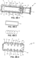
- FIG. 4B-1 to 4B-4 One such interlocking implementation is shown in FIG. 4B-1 to 4B-4 , where the substrate 16 is suspended within the housing 12 lumen 14 via an interlocking physical clamp formed by the housing components 12A, 12B. That is, in these implementations, the housing 12 consists of a first portion 12A or lower housing 12A and second portion 12B or upper housing 12B that are configured to engage, interlock or otherwise be fitted together to grasp or secure substrate(s) 16 within the lumen 14 defined by the housing 12.
- the lower housing 12B has one or more lower interlocking projections 15 or "catches" 15 disposed along the inner surface 14A of the lumen 14 within the housing 12.
- the upper housing 12B comprises one or more paired upper openings 19 or "loops" 19 are disposed within the housing wall 12C and are configured to interlock with the lower projections 15, such that the loops 19 are configured to receive the corresponding opposite projections 15, as would be understood by one of skill in the art.
- the upper and lower housings may comprise certain detent features (an example of which is shown in FIGS. 5H-5I at 66) and therefore be interlocked or "snapped" in place to form a unitary housing 12.
- the upper 12B and lower 12B housing portions may be secured to one another via other known methods.
- the lower housing 12A contains a connector 18 having an inlet 18A, certain implementations of which are described below in reference to FIGS. 6A-6C .
- the lumen 14 of the lower housing 12A is contoured 13 within to approximate the shape of the substrate(s) 16 disposed therein, as would be appreciated by one of skill in the art.
- the substrates 16 are suspended or "clipped" within the lumen 14 between lower supports 56 or tabs and upper supports or tabs 54 when the upper housing 12B is fitted to the lower housing 12A. That is, one or more tabs 56 or “clips” 56 are provided in the lower housing 12A and disposed within the contours 13. It is understood that these components can be formed within the walls of the housing 12 within the lumen, as described herein below.
- the projections 19 are configured to secure over the catches 15, and the gasket 23 creates a substantially water- or air-tight seal between the components so as to suspend the substrates 16 within the sealed lumen 14. That is, the substrates 16 are held in place by the physical clamping forces applied from the bottom clips 56 and top clips 54. After fluid has been loaded into the substrates 16, the loops 19 may be deflected or otherwise released from the catches 15, thereby separating the lower housing 12A from the upper housing 12B and allowing for the removal of the substrates 25.
- the substrate 16 according to these implementations is disposed and suspended within cartridge 10 in the lumen 14. As shown in FIG. 5A , the substrate 16 can be suspended within the lumen 14 to facilitate reliable transfer of the fluid to the substrate 16, as would be appreciated.
- the substrate 16 is disposed within the collector lumen 14 so as to be in fluidic communication with a fluidic channel 50, such as an open channel 50 having a channel opening 52.
- a fluidic channel 50 such as an open channel 50 having a channel opening 52.
- the open channel 50 can be any of the various channels described in the applications and patents referenced above, such as those that satisfy the SCF relationship, as has been previously described for example in U.S. Application No. 13/949,108 .
- the substrate 16 is thereby exposed to air on all sides, so as to facilitate accurate volume collection and drying. Further, in various implementations, the substrate 16 need not be in physical contact with the channel 50, so long as the substrate 16 is sufficiently proximal to the channel 50, fluidic bridging can occur, thereby filling the substrate 16.
- the open channel can be a microfluidic channel 50 having a U-shaped channel opening 52A with the substrate 16 disposed adjacent to the open side, as shown in FIGS. 5A and 5B .
- the open channel 50 can be a "sandwich" channel opening 52B shown in FIGS. 5C and 5D , where a portion of the substrate 16 is disposed within the "sandwich.”
- the channel opening 52 can comprise the channel geometry required to facilitate SCF.
- the ratio of the free perimeter (pf), defined by the length of the cross-section open to air or another medium, and the wetted perimeter (pw), defined by the length of the cross-section made up of solid hydrophilic material must be less than the cosine of the contact angle ( ⁇ ) of the fluid with the channel walls.
- the substrate 16 is suspended within the lumen 14 by projections, such as upper tabs 54 and / or lower tabs 56 which are affixed to the housing within the lumen 14. It is understood that many configurations are possible, and that several upper tabs 54A, 54B and / or lower tabs 56A, 56B can be disposed within the lumen 14, such that the substrate 16 can be suspended within the lumen 14. It is understood that in certain implementations, the substrate can "click" into place between the tabs 54, 56, thereby improving the transfer fluid from a channel to the substrate 16. In various implementations, the tensile strength of the substrate can provide sufficient spring force to retain the substrate in a fixed position between the various tabs 54, 56. It is also understood that in certain implementations, a spring (not shown) can be provided to urge the tabs 54, 56 into a clasping position on either face of the substrate 16.
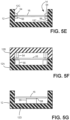
- FIGS. 5E-5I show further implementations for securing the substrate 16 within the housing 12 via projections, "clips” or tabs 54, 56 disposed on either side of the lumen 14 and configured to secure the substrate(s) 16.
- a single primary housing 12 contains bottom tabs 56A, 56B and top tabs 54A, 54B that are fixedly attached to the sides 12C of the housing 12 within the lumen 14.
- a substrate 16 may be introduced from above such that it is suspended between the bottom tabs 56 and top tabs 54.
- a lower housing 12A containing bottom tabs 56A, 56B configured to interface with a upper housing 12B having top tabs 54A, 54B so as to secure the substrate 16 therein.
- the substrate 16 can be introduced between the bottom tabs 56A, 56B and top tabs 54A, 54B, such that when the lower housing 12A and upper housing 12B are interfaced together, the substrate 16 is held in place due to the clamping force between the bottom tabs 56A, 56B and top tabs 54A, 54B.
- substrate 16 may be adhered to a single primary housing 12 via a single tab 56 projected from the top or bottom 12D of the housing 12 by way of adhesive 58.
- the adhesive 58 can be a double-side tape with plastic backing, a transfer tape without a plastic backing, or a liquid adhesive.
- FIGS. 5H-5I show cross-sectional side views of a device 10 assembly consisting of a lower housing 12A and an upper housing 12B.
- the lower housing 12A contains bottom tabs 56A, 56B disposed within the lumen 14, and features detent features or protrusions 66 disposed along on either side along the outer surface of the housing 12. It is understood that these protrusions 66 enable the upper 12B and lower 12A portions of the housing to be snapped together.
- the upper housing 12B of FIGS. 5H-5I has paired top tabs 54A, 54B disposed with the lumen 14.
- the housing 12B further has sides 63 having openings 63A therein and stops 65, wherein the upper housing 12B is thereby adapted to be capable of being snapped into place over the lower housing so as to prevent the removal of the upper housing 12B from the lower housing 12A, as would be readily appreciated.
- this catch mechanism (generally at 67) can thereby be used to secure the housing 12 together.
- a gasket 23 is also provided, as described above, such that in use when the lower housing 12A is pressed together with the upper housing 12B, the stops 65 temporarily deflect and then secure around the protrusions 66 to form the catch mechanism 67. Accordingly, the gasket 23 compresses against the lower housing 12A and the upper housing 12B, creating an air- or water-tight seal, such that the substrate 16 is fixedly suspended within the lumen 14 for use.
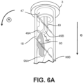
- FIG. 6A and FIGS. 6B-C Further embodiments of the fluid collection device outflow channel 49 and corresponding inlet 18A implementations are contemplated in FIG. 6A and FIGS. 6B-C .
- the coupling is achieved by way of a fitting on the connector 18, which is also a "collar" 3.
- the collar 3 can be pressure fit and include a rubber gasket, a thread, or a quarter turn lock.
- the connector 18 is therefore configured to couple directly with a fluid collection device 1 to create a fluidic and / or hermetic seal and facilitate the flow of fluid via the connector 18 into the cartridge 10.
- the connector 18 of various implementations can contain an inlet (shown for example in FIG. 4A-2 and 4B-1 at 18A and in FIGS.
- the funnel 99 and inlet 18A may be the same component.
- an outflow channel 49 can extend from an outflow tube 47 from the fluid collection device (as shown in relation to FIG. 1C ).
- the outflow channel 49 extends from the outflow tube 47 such that the distal end of the channel 49C is disposed within the connector 18, thereby providing the initial transitional point for the flow of fluid 60 into the cartridge 10.
- these outflow channels 49 contemplate outflow channel geometries that act as one-way flow valves. In this sense, the fluid 5 is able to flow by dripping into the cartridge 10, but when the device 1 and cartridge 10 are inverted, the channel 49 will not allow backflow out of the tube. Many of these geometries are described in U.S. Application No. 14/816,994 .
- FIG. 6A features an outflow channel 49 having first 49A and second 49B channel edges which are in fluidic connection with the inner surface 6 of the connector 18 and / or the inlet 18A. That is, the two channel edges 49A, 49B are in contact with the inner surface 6 of the inlet 18A such that fluid 60 that flows out of the outflow channel 49 will come in contact with the inner surface 6 of the inlet lumen 84.
- the fluid is able to flow out from the outflow channel 49 and into the inlet 18A, and when it is rotated in the direction of reference arrow A fluid 60 is brought into contact with the inner surface 6 so as to fill the inlet reservoir, discussed in relation to FIGS. 6B-C . It is understood that many other configurations are contemplated, as have been previously discussed.
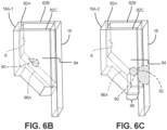
- FIGS. 6B-6C show two implementations for inlet 18A designs for the application of fluid onto substrates 16, as was shown in FIG. 4A-4B .
- the inlet 18A is in fluidic communication with the connector so as to accept the flow of fluid into the housing.
- the inlets 18A-1, 18A-2 of these implementations have several sides 82A, 82B, 82C abutting against a substrate 16 and defining an inlet lumen 84.
- a distal plane 86A is provided at the end of the lumen 84 proximal the interior of the housing.
- the inlet 18A-1 fluid 60 makes contact with a substrate 16 at a vertical wall (shown here at 82A within the lumen 84).
- a substrate 16 at a vertical wall (shown here at 82A within the lumen 84).
- any fluid that enters the inlet 18A-1 may only exit through the substrate 16 and components of the fluid may be filtered as the fluid flows down the length of substrate 16.
- an alternate implementation of the inlet 18A-2 may instead have a gap 100 separating it from a substrate 16.
- fluid may exit the inlet 18A-2 by flowing through the substrate 16 or by flowing through the gap 88. It is understood that typically, fluid flows more quickly out of the inlet 18A-2 of FIG. 6B than the inlet 18A-1 of FIG. 6A , due to the presence of the gap 88, with specific flow rate dependent on the size of gap 88 and the hydrophilicity of the inlet 18A-2, as would be appreciated by a skilled artisan.
- the width 88 of the gap 88 is less than approximately 100 ⁇ m, the flow of fluid through gap 88 is minimal due to the effects of surface tension.
- the width 88 is greater than approximately 200 ⁇ m and less than approximately 400 ⁇ m, the majority of the fluid flows out of inlet 18A-2 through the gap 88 along the entire width of substrate 16, as sufficient fluid must accumulate at gap 88 before the fluid has sufficient hydrostatic pressure to overcome the effects of surface tension.
- the fluid reaches distal regions of substrate 16 by first flowing down the outer surface of substrate 16 and then transporting within its fibers. Overall, the rate of filling of substrate 16 is increased when using inlets 18A-2 like those of FIG. 6B as opposed to inlets 18A-1 without a gap 88, as depicted in FIG. 6A , and less filtering of fluid components within the substrate 16.
- the filtering of red blood cells from whole blood occurs. It is further understood that when the distance of the gap 100 is greater than approximately 500 ⁇ m, the fluid is able to flow out of the inlet 18A-2 with minimal accumulation along the gap 100. Thus, fluid is able to flow down the side or edge of the substrate 16 without covering its entire width, which can result in incomplete filling of substrate 16. While the widths 100A discussed above are relevant when the fluid used is whole blood and the width of the substrate is approximately 8 mm, the gap 88 distances used may vary in alternate implementations based on factors such as fluid viscosity, material surface properties, surface treatments, and the specific geometries of the inlet and the substrate.
- substrates16 may consist of multiple discrete substrates 16A, 16B, 16C, 16D or a single continuous perforated strip 16P comprising several subunits 16P-1, 16P-2, 16P-3, 16P-4.
- multiple round substrates 16A, 16B, 16C, 16D are arranged such that they are partially overlapping. It is understood that fluid is able to flow from one substrate to the next through regions of overlap. Substrates of alternate geometries such as ellipses or rectangles may also be used in place of round substrates.
- a single continuous substrate 16P may be separated into subunits 16P-1, 16P-2, 16P-3, 16P-4 by perforations 160.
- the perforations 160 retain fluidic continuity during fluid collection, while allowing the substrate 16 to be broken apart into individual segments 16P-1, 16P-2, 16P-3, 16P following fluid collection.
- the perforated substrate 16P need not be limited only to a rectangular geometry with rectangular components.
- a single substrate 16P made out of smaller perforated circular or ellipsoid segments may also be used.
- FIGS. 8A, 8B and 8C certain implementations of the cartridge 10 facilitate the controlled, sequential filling of several substrates 16A, 16B.
- fluid 60 passing through the channel 50 (shown by reference arrow D) is able to come into contact with a first substrate 16A (shown in FIG. 8A ), flow into ( FIG. 8B ) and eventually saturate 62 the substrate 16A.
- a second substrate 16B disposed adjacent to the first 16A but opposite the channel 50 will begin filling after the first 16A has become saturated such that the fluid has reach the intersection 64 between the substrates 16A, 16B. It is understood that the intersection 64 between the substrates 16A, 16B need not involve direct physical contact between the substrates 16A, 16B: the substrates 16A, 16B merely need to be disposed sufficiently proximally to allow for fluidic bridging between the first 16A and second 16B substrates. Further discussion of various implementations is found below, for example in relation to FIGS. 16A-C .
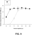
- FIG. 9 This sequential saturation of the substrates 16A, 16B is demonstrated in FIG. 9 .
- controlled volumes of fluid were introduced into a collector having first (black circles) and second (white circles) substrates configured to be saturated at 50 ⁇ L were disposed substantially as shown in FIGS. 8A-8C .
- the second substrate (white circles) does not begin to fill until the first has reached the saturation point of approximately 50 ⁇ L.
- the substrates do not retain any additional fluid. Further discussion of excess fluid management is found below, for example in relation to FIGS. 10A and 11A . It is understood that the volumetric capacities of these components are correlated to surface area - in various implementations the capacity can be any size.
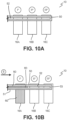
- the substrates 16A, 16B, 16C are in fluidic communication with a channel 50, such as an open channel satisfying the SCF relationship, as shown in the implementations of FIGS. 10A-10B .
- a plurality of substrates 16A, 16B, 16C are provided that are, in this embodiment, substrate(s) 16A, 16B, 16C.
- substrate(s) 16A, 16B, 16C may be utilized, such as paper discs, glass fibers, foams, porous solids and other materials capable of sufficient capillary force to self-fill with liquid that is thus sequestered in the substrate.
- the substrate provides strong capillary force, thus allowing for self-filling so long as it is not in fluidic communication with another substrate with a stronger capillary force.
- a material of similar capillary force can be adjacent to it and will absorb the overflow.
- the substrate(s) 16A, 16B, 16C are disposed within the housing (as shown variously above) so as to be in fluidic communication with and sequentially filled via the channel 50, which in this implementation is an open microfluidic channel 50 having an opening 52. It is understood that various channel 50 shapes and geometries may be utilized, and that certain implementations will result in spontaneous capillary flow along the channel 50, as has been previously described in the incorporated references. It is further understood that in implementations having an opening 52, the substrate(s) 16A, 16B, 16C can be disposed adjacent to the opening 52 to facilitate fluid 60 transfer and / or bridging, as would be apparent to one of skill in the art.
- the substrate(s) 16A, 16B, 16C are disposed in a linear orientation inside the housing.
- preferential saturation facilitates sequential saturation by the open channel 50, as described herein.
- a first substrate 16A is disposed adjacent to the proximal channel end 51 and a last substrate 16C is disposed adjacent the distal end 53.
- the capillarity of the substrate(s) 16A, 16B, 16C in these implementations is greater than the capillarity of the open channel 50, such that fluid 60 flowing into the collector (shown by reference arrow E) sequentially saturates each substrate 16A sequentially (designated by I°, II°, and III°), prior to advancing distally through the channel 50 to subsequent substrate(s) 16B, 16C. It is understood that further numbers of substrates or substrate(s) can be provided.
- these implementations therefore allow for the preferential saturation of the proximal substrate 16A prior to saturation of the subsequent substrate(s) 16B, 16C.
- sequentially saturation occurs because fluid 60 will preferentially enter the first substrate 16A prior to saturation, at which point it will continue to flow through the channel 50.
- an overflow reservoir 70 can be provided.
- the cartridge 10 has an overflow reservoir 70, such as a sponge or high-absorbance paper 70, though it is understood that various other substances or structures can be used as well.
- the overflow reservoir 70 is able to collect the additional fluid and prevent pooling within the housing. It is understood that in certain implementations the assay substrates 16A, 16B can have fixed saturation volumes - for example 50 ⁇ L, 100 ⁇ L or 150 ⁇ L - while the overflow reservoir 70 can have a much larger saturation volume. As is shown in the implementation of FIG. 11A , the overflow reservoir can be used in conjunction with adjacent substrate(s) 16A, 16B, such as in the implementations of FIGS.
- the overflow reservoir 70 is used in conjunction with an open channel 50 and spaced substrate 16A, 16B configuration, like that of FIGS. 10A and 10B . It would apparent to one of skill in the art that further configurations are possible.
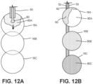
- a substrate 16A can comprise a reagent 80A, such as a blood lysis reagent, a nucleic acid stabilization reagent, a chaperone molecule to protect a specific blood analyte or other known reagents used in the clinical analysis of fluids such as blood or plasma: myriad examples are known.
- the reagent 80A can be applied to one or more of the substrates 16A prior to use, such that fluid 60 saturating the substrate 16A is exposed to the reagent 80A prior to drying and storage.
- three adjacent substrates 16A, 16B, 16C are shown, but in additional implementations, other configurations are of course possible.
- the substrates 16A, 16B, 16C are in fluidic communication with an open channel 50.
- the downstream substrates 16B, 16C have been treated with reagents 80B, 80C.
- certain reagents 80B, 80C can be pre-applied to any or all of the substrates 16A, 16B, 16C. It is understood that in certain circumstances it is beneficial to apply certain reagents 80B, 80C to downstream substrates 16B, 16C so as to prevent cross-contamination, as certain reagent may enter the fluid 60 and be carried down the channel 50 into a downstream substrate.
- the sequential filling of the substrates 16A, 16B, 16C via a channel 50 facilitates substrate bypass, meaning the flowing fluid is not drawn toward a saturated substrate 16A, instead passing by the saturated substrate 16A to fill a subsequent substrate 16B, 16C with minor co-mingling or contamination from upstream substrate reagents.
- substrate bypass meaning the flowing fluid is not drawn toward a saturated substrate 16A, instead passing by the saturated substrate 16A to fill a subsequent substrate 16B, 16C with minor co-mingling or contamination from upstream substrate reagents.
- substrates 16A, 16B, 16C, 16D of various capacities can be distributed along the channel 50 for sequential saturation.
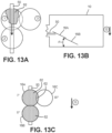
- certain implementations of the cartridge 10 can use gravity (shown generally with reference arrow G) to control the sequence of substrate 16A, 16B, 16C saturation 62 from the channel 50.
- gravity shown generally with reference arrow G
- the force of gravity combined with the capillarity of the substrates 16A, 16B, 16C will lead to preferential fluid 60 saturation in a determined sequence, as is generally shown in FIG. 13C .
- the substrate 16 can utilize selective fluidic bridging. That is, in certain implementations, a substrate 16 can be provided that has a first substrate portion 16A and a second substrate portion 16B disposed across a gap 90. In certain of these implementations, a shunt 92 is also provided adjacent to, and in direct communication with the first substrate portion 16A. In the implementations of FIGS. 11A -C, the static substrate reservoir 19 is provided as a dogleg shunt 92. Other implementations are possible.
- a second substrate portion 16B is disposed "below" the first 16A relative to gravity (G), and this second portion 16B can act as an overflow reservoir.
- the initial flow of fluid 60 is in the direction of gravity (shown by reference arrow G).
- that additional fluid 60A will begin to flow laterally (shown by reference arrow L) into the shunt 92.
- FIG. 14A-14B shows that additional fluid 60A will begin to flow laterally (shown by reference arrow L) into the shunt 92.
- a fluidic bridge 61 can cross the gap 90, so as to transfer additional fluid 60 into the second portion 16B (reference arrow G 2 ).
- the fluid 60A contained in the shunt 92 is therefore able to be static, such that additional fluid entering the substrate passes through the passes through the first substrate portion16A - bypassing the shunt 92, when a specified volume of fluid 60A is being held statically - so as to bridge 61 and enters the second substrate portion 16B via the gap 90.
- These implementations can be used to collect blood 60A in the shunt 92 to present fluid exchanges or to soak excess fluid and control the fluid volume in the first substrate. As would be apparent to a skilled artisan, many configurations of these elements are possible.
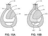
- FIGS.15A-15B An alternate bridging substrate 16 is shown in the implementations of FIGS.15A-15B .
- the use of a separate second portion 16B can provide overflow collection during the collection of plasma 60A.
- the first portion 16A is comprised of separation paper 16A that preferentially allows plasma 60A flow.
- blood 60B is separated from plasma 60A, in that plasma 60A saturates the second end 96 prior to the arrival of blood 60B.
- the second substrate end 96 can be selectively saturated with plasma 60A, so that plasma 60A is retained in that second end 96, while blood 60B remains in the first end longer and then selectively bridges 60C to the second substrate portion 16B as needed.
- the arrangement of the substrates and selection of substrate type and shape can allow the individual substrates to perform a variety of modular, or networked features and actions on blood flowing into the collector.
- the substrates can preferentially absorb blood, plasma or other fluids; transfer blood or other fluids with minimal volumes absorbed; apply a reagent or other treatment to the blood or fluid and / or filter the fluid blood. Additional features are also contemplated.
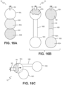
- FIG. 16A three substrates 16A, 16B, 16C are provided, with various reagents 80 A, 80B being incorporated into the downstream substrates 16B, 16C, as has been previously described above.
- these networks of substrates can be modular in nature, and incorporate any number of variations depending on the assays of interest.
- the substrate pore size can be used to control the capillary pressure or force between the various substrates and thereby control fluid flow and saturation.
- a network comprising three substrates 16 A, 16B, 16C.
- the second substrate 16B is an elongate paper channel 16B of separation paper, as was discussed in relation to FIG. 15A-B .
- the fluid enters the separation channel 16B.
- the plasma 60 A proceeds faster than whole blood 60, such that the third substrate 16C is selectively saturated with plasma 60A while the whole blood 60 is retained upstream, in the first substrate 16A and the portion of the channel 16B adjacent the first substrate.
- an additional overflow substrate 16D is provided and disposed adjacent to the first 16 A.
- excess blood 60 can be directed into the overflow substrate while plasma saturates the third substrate 16C.
- myriad additional combinations are possible.
Landscapes
- Health & Medical Sciences (AREA)
- Life Sciences & Earth Sciences (AREA)
- General Health & Medical Sciences (AREA)
- Engineering & Computer Science (AREA)
- Public Health (AREA)
- Heart & Thoracic Surgery (AREA)
- Medical Informatics (AREA)
- Molecular Biology (AREA)
- Surgery (AREA)
- Animal Behavior & Ethology (AREA)
- Pathology (AREA)
- Veterinary Medicine (AREA)
- Biomedical Technology (AREA)
- Hematology (AREA)
- Physics & Mathematics (AREA)
- Biophysics (AREA)
- Chemical & Material Sciences (AREA)
- Dermatology (AREA)
- Chemical Kinetics & Catalysis (AREA)
- Clinical Laboratory Science (AREA)
- Analytical Chemistry (AREA)
- Pain & Pain Management (AREA)
- Manufacturing & Machinery (AREA)
- Sampling And Sample Adjustment (AREA)
- Measurement Of The Respiration, Hearing Ability, Form, And Blood Characteristics Of Living Organisms (AREA)
- Automatic Analysis And Handling Materials Therefor (AREA)
- Investigating Or Analysing Biological Materials (AREA)
Claims (9)
- Une cartouche de fluide (10), comprenant :un raccord (18) d'une forme et de dimensions permettant de l'accoupler de manière amovible à un dispositif de collecte de fluide (1) pour recevoir un fluide du dispositif de collecte de fluide (1) ;un boîtier (12) accouplé au raccord (18), le boîtier (12) définissant une lumière allongée (14) ayant une première partie d'extrémité à proximité du raccord (18) et une deuxième partie d'extrémité opposée à la première partie d'extrémité, et la première partie d'extrémité de la lumière étant accouplée fluidiquement au raccord (18) pour recevoir le fluide du dispositif de collecte de fluide (1) ; etplusieurs substrats poreux (16A, 16B, 16C) positionnés linéairement dans la lumière entre les première et deuxième parties d'extrémité, les substrats (16A, 16B, 16C) étant espacés l'un de l'autre et n'étant pas en contact l'un avec l'autre le long de la lumière (14), chaque substrat (16A, 16B, 16C) étant chacun configuré pour collecter séquentiellement au moins une portion du fluide reçu du dispositif de collecte de fluide (1).
- La cartouche de fluide (10) selon la revendication 1, dans laquelle le boîtier (12) inclut des parties de boîtier qui s'emboîtent.
- La cartouche de fluide (10) selon la revendication 2, dans laquelle le boîtier (12) inclut une pluralité de languettes configurées pour fixer les substrats dans la lumière.
- La cartouche de fluide (10) selon la revendication 1, dans laquelle le boîtier (12) inclut un couvercle amovible (20) fixé sur la lumière.
- La cartouche de fluide (10) selon la revendication 1, dans laquelle le raccord (18) inclut un ou plusieurs canaux fluidiques (50), et dans laquelle les substrats sont disposés dans la lumière et en communication fluidique avec le ou les canaux fluidiques.
- La cartouche de fluide (10) selon la revendication 5, dans laquelle le ou les canaux fluidiques (50) sont des canaux microfluidiques ouverts.
- La cartouche de fluide (10) selon la revendication 1, comprenant en outre un réservoir de trop-plein (70) positionné dans le boîtier.
- La cartouche de fluide (10) selon la revendication 1, dans laquelle le ou les substrats (16A, 16B, 16C) incluent un ou plusieurs réactifs.
- La cartouche de fluide (10) selon la revendication 1, dans laquelle le boîtier inclut un ou plusieurs évents (24).
Applications Claiming Priority (2)
| Application Number | Priority Date | Filing Date | Title |
|---|---|---|---|
| US201662397751P | 2016-09-21 | 2016-09-21 | |
| PCT/US2017/052754 WO2018057760A1 (fr) | 2016-09-21 | 2017-09-21 | Administration de fluides corporels sur un substrat fibreux et systèmes et dispositifs associés |
Publications (4)
| Publication Number | Publication Date |
|---|---|
| EP3515521A1 EP3515521A1 (fr) | 2019-07-31 |
| EP3515521A4 EP3515521A4 (fr) | 2020-05-13 |
| EP3515521B1 true EP3515521B1 (fr) | 2023-10-25 |
| EP3515521C0 EP3515521C0 (fr) | 2023-10-25 |
Family
ID=61617628
Family Applications (1)
| Application Number | Title | Priority Date | Filing Date |
|---|---|---|---|
| EP17853907.8A Active EP3515521B1 (fr) | 2016-09-21 | 2017-09-21 | Cartouche de liquide pour l'administration de fluides corporels sur un substrat fibreux |
Country Status (4)
| Country | Link |
|---|---|
| US (3) | US11523805B2 (fr) |
| EP (1) | EP3515521B1 (fr) |
| CN (2) | CN115844462A (fr) |
| WO (1) | WO2018057760A1 (fr) |
Families Citing this family (22)
| Publication number | Priority date | Publication date | Assignee | Title |
|---|---|---|---|---|
| WO2013112877A1 (fr) | 2012-01-25 | 2013-08-01 | Tasso, Inc. | Dispositif portatif pour le prélèvement, la collecte, et l'analyse de fluide corporel |
| WO2016019388A1 (fr) | 2014-08-01 | 2016-02-04 | Tasso, Inc. | Dispositifs, systèmes et procédés de collecte microfluidique, de manipulation et de transfert de fluides améliorés par la gravité |
| HK1258397A1 (zh) | 2015-09-09 | 2019-11-08 | Drawbridge Health, Inc. | 用於样品收集、稳定化和保存的系统、方法和装置 |
| CN114209315B (zh) | 2015-12-21 | 2024-10-15 | 塔索公司 | 用于流体收集中的致动和缩回的装置、系统和方法 |
| CN120820389A (zh) | 2016-04-22 | 2025-10-21 | 贝克顿·迪金森公司 | 多重聚合染料装置及其使用方法 |
| EP3515521B1 (fr) | 2016-09-21 | 2023-10-25 | Tasso, Inc. | Cartouche de liquide pour l'administration de fluides corporels sur un substrat fibreux |
| SG10201911879UA (en) | 2017-01-10 | 2020-01-30 | Drawbridge Health Inc | Devices, systems, and methods for sample collection |
| JP7058662B2 (ja) | 2017-02-08 | 2022-04-22 | ベクトン・ディキンソン・アンド・カンパニー | 乾燥色素試薬装置、ならびにその製造及び使用方法 |
| WO2020056382A1 (fr) | 2018-09-14 | 2020-03-19 | Erwin Berthier | Dispositifs de collecte de liquides corporels et procédés apparentés |
| US11992844B2 (en) | 2018-11-13 | 2024-05-28 | Becton, Dickinson And Company | Dried reagent strainers and methods for making and using the same |
| WO2021222066A1 (fr) * | 2020-04-27 | 2021-11-04 | Tasso, Inc. | Dispositifs pour le stockage sécurisé de fluides corporels, et systèmes et procédés associés |
| US12053284B2 (en) | 2021-11-08 | 2024-08-06 | Satio, Inc. | Dermal patch for collecting a physiological sample |
| US12029562B2 (en) | 2021-04-14 | 2024-07-09 | Satio, Inc. | Dermal patch system |
| US12048543B2 (en) * | 2021-11-08 | 2024-07-30 | Satio, Inc. | Dermal patch for collecting a physiological sample with removable vial |
| US12178979B2 (en) | 2021-10-13 | 2024-12-31 | Satio, Inc. | Dermal patch for delivering a pharmaceutical |
| US11964121B2 (en) | 2021-10-13 | 2024-04-23 | Satio, Inc. | Mono dose dermal patch for pharmaceutical delivery |
| US11877848B2 (en) | 2021-11-08 | 2024-01-23 | Satio, Inc. | Dermal patch for collecting a physiological sample |
| US12023156B2 (en) | 2021-10-13 | 2024-07-02 | Satio, Inc. | Dermal patch for collecting a physiological sample |
| US12214346B2 (en) | 2021-10-13 | 2025-02-04 | Satio, Inc. | Dermal patch with a diagnostic test strip |
| US11478175B1 (en) | 2021-10-20 | 2022-10-25 | Paulus Holdings Limited | Devices for collecting capillary blood and methods for same |
| US11957465B2 (en) | 2022-08-23 | 2024-04-16 | Reddrop Dx, Inc. | Accelerated ergonomic collection of capillary blood |
| KR102914237B1 (ko) * | 2023-11-20 | 2026-01-20 | 한국공학대학교산학협력단 | 종이 기반 미세유체 칩을 이용한 다중물질 검출용 종이센서 및 다중물질의 검출방법 |
Citations (1)
| Publication number | Priority date | Publication date | Assignee | Title |
|---|---|---|---|---|
| WO2016074046A1 (fr) * | 2014-11-14 | 2016-05-19 | Axxin Pty Ltd | Ensemble de collecte et de stockage d'échantillon biologique |
Family Cites Families (30)
| Publication number | Priority date | Publication date | Assignee | Title |
|---|---|---|---|---|
| US6016345A (en) | 1993-11-02 | 2000-01-18 | Home Access Health Corporation | Method and system for anonymously testing for a human malady |
| US6372514B1 (en) * | 1998-09-18 | 2002-04-16 | Syntron Bioresearch, Inc. | Even fluid front for liquid sample on test strip device |
| CA2353066A1 (fr) | 1998-12-29 | 2000-07-06 | Flexsite Diagnostics, Inc. | Recueil d'urine pour analyse a distance et son procede d'utilisation |
| US7604775B2 (en) | 2002-08-12 | 2009-10-20 | Bayer Healthcare Llc | Fluid collecting and monitoring device |
| US6981948B2 (en) | 2002-11-18 | 2006-01-03 | Depuy Spine, Inc. | Bone marrow aspiration system |
| US9119577B2 (en) * | 2006-03-01 | 2015-09-01 | Home Access Health Corporation | Specimen collection device |
| GB2440119A (en) | 2006-07-18 | 2008-01-23 | Owen Mumford Ltd | Skin Pricking Device |
| US8469986B2 (en) | 2007-03-30 | 2013-06-25 | Stat Medical Devices, Inc. | Lancet device with combined trigger and cocking mechanism and method |
| EP2030567A1 (fr) * | 2007-08-31 | 2009-03-04 | Roche Diagnostics GmbH | Appareil d'analyse destiné à la détermination d'un analyte dans un liquide corporel, entrepôt pour un appareil d'analyse et procédé de production d'une plaie et pour l'examen d'un liquide corporel s'écoulant |
| WO2009123592A1 (fr) | 2008-04-03 | 2009-10-08 | Zyomyx, Inc. | Dispositif et procédé d'analyse d'échantillons avec déplétion du contenu en analytes |
| KR101147534B1 (ko) | 2009-06-02 | 2012-05-21 | 주식회사 인포피아 | 시료 채취 및 주입 기구 |
| GB2483077A (en) * | 2010-08-25 | 2012-02-29 | Concateno Uk Ltd | Sample testing assay apparatus and method |
| EP2484448A1 (fr) * | 2011-02-03 | 2012-08-08 | Universite De Geneve | Dispositifs au format non carte pour la collecte, le stockage et l'analyse de tâches de fluide corporel séchées et procédés correspondants |
| AU2012249683A1 (en) * | 2011-04-29 | 2013-11-14 | Seventh Sense Biosystems, Inc. | Devices and methods for collection and/or manipulation of blood spots or other bodily fluids |
| WO2013028765A1 (fr) * | 2011-08-22 | 2013-02-28 | Waters Technologies Corporation | Dispositif microfluidique avec interface pour carte dbs |
| WO2013112877A1 (fr) * | 2012-01-25 | 2013-08-01 | Tasso, Inc. | Dispositif portatif pour le prélèvement, la collecte, et l'analyse de fluide corporel |
| SG194252A1 (en) | 2012-04-20 | 2013-11-29 | Medipurpose Pte Ltd | A lancet |
| WO2013168165A2 (fr) * | 2012-05-10 | 2013-11-14 | Stimatix Gi Ltd. | Appareillage pour stomie |
| ES2635596T3 (es) * | 2012-06-20 | 2017-10-04 | Fabpulous B.v | Dispositivo y método de prueba rápida |
| AU2013356680A1 (en) * | 2012-12-05 | 2015-05-28 | Theranos Ip Company, Llc | Systems, devices, and methods for bodily fluid sample collection and transport |
| MX365324B (es) * | 2013-03-15 | 2019-05-29 | Theranos Ip Co Llc | Metodos y dispositivos para recoleccion de muestras y separacion de muestras. |
| WO2014172245A1 (fr) * | 2013-04-15 | 2014-10-23 | Becton, Dickinson And Company | Dispositif de prélèvement d'un liquide biologique |
| CA2937991A1 (fr) | 2014-01-28 | 2015-08-06 | Intrinsyk, LLC | Ensemble lancette |
| PL234889B1 (pl) | 2014-02-14 | 2020-04-30 | Htl Strefa Spolka Akcyjna | Urządzenie nacinające skórę |
| US10779757B2 (en) | 2014-08-01 | 2020-09-22 | Tasso, Inc. | Devices, systems and methods for gravity-enhanced microfluidic collection, handling and transferring of fluids |
| WO2016019388A1 (fr) * | 2014-08-01 | 2016-02-04 | Tasso, Inc. | Dispositifs, systèmes et procédés de collecte microfluidique, de manipulation et de transfert de fluides améliorés par la gravité |
| US10939861B2 (en) * | 2014-08-13 | 2021-03-09 | Simplexity Product Development Inc. | Dried blood spot collection device |
| EP3515521B1 (fr) | 2016-09-21 | 2023-10-25 | Tasso, Inc. | Cartouche de liquide pour l'administration de fluides corporels sur un substrat fibreux |
| WO2021076846A1 (fr) | 2019-10-18 | 2021-04-22 | Tasso, Inc. | Dispositifs de séparation de plasma et procédés associés |
| JP2023524369A (ja) | 2020-03-18 | 2023-06-12 | ドローブリッジ ヘルス,インコーポレイテッド | サンプル採取のためのシステムおよび方法 |
-
2017
- 2017-09-21 EP EP17853907.8A patent/EP3515521B1/fr active Active
- 2017-09-21 CN CN202211379095.3A patent/CN115844462A/zh active Pending
- 2017-09-21 WO PCT/US2017/052754 patent/WO2018057760A1/fr not_active Ceased
- 2017-09-21 CN CN201780072026.9A patent/CN109996571B/zh active Active
- 2017-09-21 US US15/711,746 patent/US11523805B2/en active Active
-
2021
- 2021-02-26 US US17/186,483 patent/US11622750B2/en active Active
-
2023
- 2023-03-17 US US18/186,114 patent/US12458328B2/en active Active
Patent Citations (1)
| Publication number | Priority date | Publication date | Assignee | Title |
|---|---|---|---|---|
| WO2016074046A1 (fr) * | 2014-11-14 | 2016-05-19 | Axxin Pty Ltd | Ensemble de collecte et de stockage d'échantillon biologique |
Also Published As
| Publication number | Publication date |
|---|---|
| CN109996571A (zh) | 2019-07-09 |
| US20240090880A1 (en) | 2024-03-21 |
| EP3515521A4 (fr) | 2020-05-13 |
| US20210177383A1 (en) | 2021-06-17 |
| US11523805B2 (en) | 2022-12-13 |
| US20180078241A1 (en) | 2018-03-22 |
| WO2018057760A1 (fr) | 2018-03-29 |
| EP3515521A1 (fr) | 2019-07-31 |
| US11622750B2 (en) | 2023-04-11 |
| EP3515521C0 (fr) | 2023-10-25 |
| US12458328B2 (en) | 2025-11-04 |
| CN109996571B (zh) | 2022-11-29 |
| CN115844462A (zh) | 2023-03-28 |
Similar Documents
| Publication | Publication Date | Title |
|---|---|---|
| US12458328B2 (en) | Methods for delivery of bodily fluids onto a fibrous substrate | |
| US12121893B2 (en) | Pinch to open sample collection device | |
| US11358138B2 (en) | Fluid sample collection device | |
| JP6799043B2 (ja) | 生物体液の極微標本管理装置 | |
| US12186745B2 (en) | Fluidic system for taking in, dispensing and moving liquids, method for processing fluids in a fluidic system | |
| AU2003215214B2 (en) | Fluid processing and control | |
| US11484877B2 (en) | Blood metering device with desiccant and support for storage media and inlay with flange | |
| JP4513085B2 (ja) | 試料の容器 | |
| US20230398540A1 (en) | Simultaneous spot test and storage of blood samples | |
| EP3218698B1 (fr) | Ensemble de collecte et de stockage d'échantillon biologique | |
| EP1587623A2 (fr) | Dispositifs microfluidiques pour la manipulation et l'analyse de fluides | |
| EP3886701B1 (fr) | Dispositif de collecte d'échantillon de fluide biologique et son procédé d'utilisation | |
| WO2019231837A1 (fr) | Dispositif de mesure de sang comprenant un déshydratant et un support de support de stockage et d'incrustation avec bride | |
| HK40030473A (en) | Fluid sample collection device |
Legal Events
| Date | Code | Title | Description |
|---|---|---|---|
| STAA | Information on the status of an ep patent application or granted ep patent |
Free format text: STATUS: THE INTERNATIONAL PUBLICATION HAS BEEN MADE |
|
| PUAI | Public reference made under article 153(3) epc to a published international application that has entered the european phase |
Free format text: ORIGINAL CODE: 0009012 |
|
| STAA | Information on the status of an ep patent application or granted ep patent |
Free format text: STATUS: REQUEST FOR EXAMINATION WAS MADE |
|
| 17P | Request for examination filed |
Effective date: 20190409 |
|
| AK | Designated contracting states |
Kind code of ref document: A1 Designated state(s): AL AT BE BG CH CY CZ DE DK EE ES FI FR GB GR HR HU IE IS IT LI LT LU LV MC MK MT NL NO PL PT RO RS SE SI SK SM TR |
|
| AX | Request for extension of the european patent |
Extension state: BA ME |
|
| RIN1 | Information on inventor provided before grant (corrected) |
Inventor name: MOGA, BEN Inventor name: BERTHIER, ERWIN Inventor name: CASAVANT, BEN |
|
| DAV | Request for validation of the european patent (deleted) | ||
| DAX | Request for extension of the european patent (deleted) | ||
| A4 | Supplementary search report drawn up and despatched |
Effective date: 20200409 |
|
| RIC1 | Information provided on ipc code assigned before grant |
Ipc: A61B 5/00 20060101ALI20200403BHEP Ipc: A61B 5/153 20060101ALI20200403BHEP Ipc: B01L 3/00 20060101ALI20200403BHEP Ipc: A61B 5/15 20060101ALI20200403BHEP Ipc: A61M 1/00 20060101AFI20200403BHEP Ipc: A61B 10/00 20060101ALI20200403BHEP |
|
| STAA | Information on the status of an ep patent application or granted ep patent |
Free format text: STATUS: EXAMINATION IS IN PROGRESS |
|
| 17Q | First examination report despatched |
Effective date: 20220905 |
|
| GRAP | Despatch of communication of intention to grant a patent |
Free format text: ORIGINAL CODE: EPIDOSNIGR1 |
|
| STAA | Information on the status of an ep patent application or granted ep patent |
Free format text: STATUS: GRANT OF PATENT IS INTENDED |
|
| INTG | Intention to grant announced |
Effective date: 20230508 |
|
| GRAS | Grant fee paid |
Free format text: ORIGINAL CODE: EPIDOSNIGR3 |
|
| GRAA | (expected) grant |
Free format text: ORIGINAL CODE: 0009210 |
|
| STAA | Information on the status of an ep patent application or granted ep patent |
Free format text: STATUS: THE PATENT HAS BEEN GRANTED |
|
| AK | Designated contracting states |
Kind code of ref document: B1 Designated state(s): AL AT BE BG CH CY CZ DE DK EE ES FI FR GB GR HR HU IE IS IT LI LT LU LV MC MK MT NL NO PL PT RO RS SE SI SK SM TR |
|
| REG | Reference to a national code |
Ref country code: GB Ref legal event code: FG4D |
|
| REG | Reference to a national code |
Ref country code: CH Ref legal event code: EP |
|
| REG | Reference to a national code |
Ref country code: DE Ref legal event code: R096 Ref document number: 602017075808 Country of ref document: DE |
|
| REG | Reference to a national code |
Ref country code: IE Ref legal event code: FG4D |
|
| U01 | Request for unitary effect filed |
Effective date: 20231025 |
|
| U07 | Unitary effect registered |
Designated state(s): AT BE BG DE DK EE FI FR IT LT LU LV MT NL PT SE SI Effective date: 20231030 |
|
| PG25 | Lapsed in a contracting state [announced via postgrant information from national office to epo] |
Ref country code: GR Free format text: LAPSE BECAUSE OF FAILURE TO SUBMIT A TRANSLATION OF THE DESCRIPTION OR TO PAY THE FEE WITHIN THE PRESCRIBED TIME-LIMIT Effective date: 20240126 |
|
| PG25 | Lapsed in a contracting state [announced via postgrant information from national office to epo] |
Ref country code: IS Free format text: LAPSE BECAUSE OF FAILURE TO SUBMIT A TRANSLATION OF THE DESCRIPTION OR TO PAY THE FEE WITHIN THE PRESCRIBED TIME-LIMIT Effective date: 20240225 |
|
| PG25 | Lapsed in a contracting state [announced via postgrant information from national office to epo] |
Ref country code: ES Free format text: LAPSE BECAUSE OF FAILURE TO SUBMIT A TRANSLATION OF THE DESCRIPTION OR TO PAY THE FEE WITHIN THE PRESCRIBED TIME-LIMIT Effective date: 20231025 |
|
| PG25 | Lapsed in a contracting state [announced via postgrant information from national office to epo] |
Ref country code: IS Free format text: LAPSE BECAUSE OF FAILURE TO SUBMIT A TRANSLATION OF THE DESCRIPTION OR TO PAY THE FEE WITHIN THE PRESCRIBED TIME-LIMIT Effective date: 20240225 Ref country code: GR Free format text: LAPSE BECAUSE OF FAILURE TO SUBMIT A TRANSLATION OF THE DESCRIPTION OR TO PAY THE FEE WITHIN THE PRESCRIBED TIME-LIMIT Effective date: 20240126 Ref country code: ES Free format text: LAPSE BECAUSE OF FAILURE TO SUBMIT A TRANSLATION OF THE DESCRIPTION OR TO PAY THE FEE WITHIN THE PRESCRIBED TIME-LIMIT Effective date: 20231025 |
|
| PG25 | Lapsed in a contracting state [announced via postgrant information from national office to epo] |
Ref country code: RS Free format text: LAPSE BECAUSE OF FAILURE TO SUBMIT A TRANSLATION OF THE DESCRIPTION OR TO PAY THE FEE WITHIN THE PRESCRIBED TIME-LIMIT Effective date: 20231025 Ref country code: PL Free format text: LAPSE BECAUSE OF FAILURE TO SUBMIT A TRANSLATION OF THE DESCRIPTION OR TO PAY THE FEE WITHIN THE PRESCRIBED TIME-LIMIT Effective date: 20231025 Ref country code: NO Free format text: LAPSE BECAUSE OF FAILURE TO SUBMIT A TRANSLATION OF THE DESCRIPTION OR TO PAY THE FEE WITHIN THE PRESCRIBED TIME-LIMIT Effective date: 20240125 Ref country code: HR Free format text: LAPSE BECAUSE OF FAILURE TO SUBMIT A TRANSLATION OF THE DESCRIPTION OR TO PAY THE FEE WITHIN THE PRESCRIBED TIME-LIMIT Effective date: 20231025 |
|
| PG25 | Lapsed in a contracting state [announced via postgrant information from national office to epo] |
Ref country code: CZ Free format text: LAPSE BECAUSE OF FAILURE TO SUBMIT A TRANSLATION OF THE DESCRIPTION OR TO PAY THE FEE WITHIN THE PRESCRIBED TIME-LIMIT Effective date: 20231025 |
|
| REG | Reference to a national code |
Ref country code: DE Ref legal event code: R097 Ref document number: 602017075808 Country of ref document: DE |
|
| PG25 | Lapsed in a contracting state [announced via postgrant information from national office to epo] |
Ref country code: SK Free format text: LAPSE BECAUSE OF FAILURE TO SUBMIT A TRANSLATION OF THE DESCRIPTION OR TO PAY THE FEE WITHIN THE PRESCRIBED TIME-LIMIT Effective date: 20231025 |
|
| PG25 | Lapsed in a contracting state [announced via postgrant information from national office to epo] |
Ref country code: SM Free format text: LAPSE BECAUSE OF FAILURE TO SUBMIT A TRANSLATION OF THE DESCRIPTION OR TO PAY THE FEE WITHIN THE PRESCRIBED TIME-LIMIT Effective date: 20231025 Ref country code: SK Free format text: LAPSE BECAUSE OF FAILURE TO SUBMIT A TRANSLATION OF THE DESCRIPTION OR TO PAY THE FEE WITHIN THE PRESCRIBED TIME-LIMIT Effective date: 20231025 Ref country code: RO Free format text: LAPSE BECAUSE OF FAILURE TO SUBMIT A TRANSLATION OF THE DESCRIPTION OR TO PAY THE FEE WITHIN THE PRESCRIBED TIME-LIMIT Effective date: 20231025 Ref country code: CZ Free format text: LAPSE BECAUSE OF FAILURE TO SUBMIT A TRANSLATION OF THE DESCRIPTION OR TO PAY THE FEE WITHIN THE PRESCRIBED TIME-LIMIT Effective date: 20231025 |
|
| PLBE | No opposition filed within time limit |
Free format text: ORIGINAL CODE: 0009261 |
|
| STAA | Information on the status of an ep patent application or granted ep patent |
Free format text: STATUS: NO OPPOSITION FILED WITHIN TIME LIMIT |
|
| U20 | Renewal fee for the european patent with unitary effect paid |
Year of fee payment: 8 Effective date: 20240807 |
|
| 26N | No opposition filed |
Effective date: 20240726 |
|
| PG25 | Lapsed in a contracting state [announced via postgrant information from national office to epo] |
Ref country code: MC Free format text: LAPSE BECAUSE OF FAILURE TO SUBMIT A TRANSLATION OF THE DESCRIPTION OR TO PAY THE FEE WITHIN THE PRESCRIBED TIME-LIMIT Effective date: 20231025 |
|
| REG | Reference to a national code |
Ref country code: CH Ref legal event code: PL |
|
| PG25 | Lapsed in a contracting state [announced via postgrant information from national office to epo] |
Ref country code: CH Free format text: LAPSE BECAUSE OF NON-PAYMENT OF DUE FEES Effective date: 20240930 |
|
| PG25 | Lapsed in a contracting state [announced via postgrant information from national office to epo] |
Ref country code: IE Free format text: LAPSE BECAUSE OF NON-PAYMENT OF DUE FEES Effective date: 20240921 |
|
| U21 | Renewal fee for the european patent with unitary effect paid with additional fee |
Year of fee payment: 9 Effective date: 20251118 |
|
| PGFP | Annual fee paid to national office [announced via postgrant information from national office to epo] |
Ref country code: GB Payment date: 20251120 Year of fee payment: 9 |
|
| PG25 | Lapsed in a contracting state [announced via postgrant information from national office to epo] |
Ref country code: CY Free format text: LAPSE BECAUSE OF FAILURE TO SUBMIT A TRANSLATION OF THE DESCRIPTION OR TO PAY THE FEE WITHIN THE PRESCRIBED TIME-LIMIT; INVALID AB INITIO Effective date: 20170921 |
|
| PG25 | Lapsed in a contracting state [announced via postgrant information from national office to epo] |
Ref country code: HU Free format text: LAPSE BECAUSE OF FAILURE TO SUBMIT A TRANSLATION OF THE DESCRIPTION OR TO PAY THE FEE WITHIN THE PRESCRIBED TIME-LIMIT; INVALID AB INITIO Effective date: 20170921 |
|
| PG25 | Lapsed in a contracting state [announced via postgrant information from national office to epo] |
Ref country code: TR Free format text: LAPSE BECAUSE OF FAILURE TO SUBMIT A TRANSLATION OF THE DESCRIPTION OR TO PAY THE FEE WITHIN THE PRESCRIBED TIME-LIMIT Effective date: 20231025 |