EP3515529B1 - Insert pour un ensemble de tubulures sanguines permettant de faciliter un mélange d'une solution d'infusion avec un autre liquide - Google Patents
Insert pour un ensemble de tubulures sanguines permettant de faciliter un mélange d'une solution d'infusion avec un autre liquide Download PDFInfo
- Publication number
- EP3515529B1 EP3515529B1 EP17777230.8A EP17777230A EP3515529B1 EP 3515529 B1 EP3515529 B1 EP 3515529B1 EP 17777230 A EP17777230 A EP 17777230A EP 3515529 B1 EP3515529 B1 EP 3515529B1
- Authority
- EP
- European Patent Office
- Prior art keywords
- line
- blood
- insert piece
- main line
- lumen
- Prior art date
- Legal status (The legal status is an assumption and is not a legal conclusion. Google has not performed a legal analysis and makes no representation as to the accuracy of the status listed.)
- Active
Links
Images



Classifications
-
- A—HUMAN NECESSITIES
- A61—MEDICAL OR VETERINARY SCIENCE; HYGIENE
- A61M—DEVICES FOR INTRODUCING MEDIA INTO, OR ONTO, THE BODY; DEVICES FOR TRANSDUCING BODY MEDIA OR FOR TAKING MEDIA FROM THE BODY; DEVICES FOR PRODUCING OR ENDING SLEEP OR STUPOR
- A61M1/00—Suction or pumping devices for medical purposes; Devices for carrying-off, for treatment of, or for carrying-over, body-liquids; Drainage systems
- A61M1/34—Filtering material out of the blood by passing it through a membrane, i.e. hemofiltration or diafiltration
- A61M1/342—Adding solutions to the blood, e.g. substitution solutions
-
- A—HUMAN NECESSITIES
- A61—MEDICAL OR VETERINARY SCIENCE; HYGIENE
- A61M—DEVICES FOR INTRODUCING MEDIA INTO, OR ONTO, THE BODY; DEVICES FOR TRANSDUCING BODY MEDIA OR FOR TAKING MEDIA FROM THE BODY; DEVICES FOR PRODUCING OR ENDING SLEEP OR STUPOR
- A61M1/00—Suction or pumping devices for medical purposes; Devices for carrying-off, for treatment of, or for carrying-over, body-liquids; Drainage systems
- A61M1/34—Filtering material out of the blood by passing it through a membrane, i.e. hemofiltration or diafiltration
- A61M1/342—Adding solutions to the blood, e.g. substitution solutions
- A61M1/3455—Substitution fluids
- A61M1/3465—Substitution fluids using dialysate as substitution fluid
-
- A—HUMAN NECESSITIES
- A61—MEDICAL OR VETERINARY SCIENCE; HYGIENE
- A61M—DEVICES FOR INTRODUCING MEDIA INTO, OR ONTO, THE BODY; DEVICES FOR TRANSDUCING BODY MEDIA OR FOR TAKING MEDIA FROM THE BODY; DEVICES FOR PRODUCING OR ENDING SLEEP OR STUPOR
- A61M1/00—Suction or pumping devices for medical purposes; Devices for carrying-off, for treatment of, or for carrying-over, body-liquids; Drainage systems
- A61M1/34—Filtering material out of the blood by passing it through a membrane, i.e. hemofiltration or diafiltration
- A61M1/3472—Filtering material out of the blood by passing it through a membrane, i.e. hemofiltration or diafiltration with treatment of the filtrate
-
- A—HUMAN NECESSITIES
- A61—MEDICAL OR VETERINARY SCIENCE; HYGIENE
- A61M—DEVICES FOR INTRODUCING MEDIA INTO, OR ONTO, THE BODY; DEVICES FOR TRANSDUCING BODY MEDIA OR FOR TAKING MEDIA FROM THE BODY; DEVICES FOR PRODUCING OR ENDING SLEEP OR STUPOR
- A61M1/00—Suction or pumping devices for medical purposes; Devices for carrying-off, for treatment of, or for carrying-over, body-liquids; Drainage systems
- A61M1/36—Other treatment of blood in a by-pass of the natural circulatory system, e.g. temperature adaptation, irradiation ; Extra-corporeal blood circuits
- A61M1/3672—Means preventing coagulation
-
- A—HUMAN NECESSITIES
- A61—MEDICAL OR VETERINARY SCIENCE; HYGIENE
- A61M—DEVICES FOR INTRODUCING MEDIA INTO, OR ONTO, THE BODY; DEVICES FOR TRANSDUCING BODY MEDIA OR FOR TAKING MEDIA FROM THE BODY; DEVICES FOR PRODUCING OR ENDING SLEEP OR STUPOR
- A61M39/00—Tubes, tube connectors, tube couplings, valves, access sites or the like, specially adapted for medical use
- A61M2039/0009—Assemblies therefor designed for particular applications, e.g. contrast or saline injection, suction or irrigation
- A61M2039/0027—Assemblies therefor designed for particular applications, e.g. contrast or saline injection, suction or irrigation for mixing several substances from different containers
-
- A—HUMAN NECESSITIES
- A61—MEDICAL OR VETERINARY SCIENCE; HYGIENE
- A61M—DEVICES FOR INTRODUCING MEDIA INTO, OR ONTO, THE BODY; DEVICES FOR TRANSDUCING BODY MEDIA OR FOR TAKING MEDIA FROM THE BODY; DEVICES FOR PRODUCING OR ENDING SLEEP OR STUPOR
- A61M2206/00—Characteristics of a physical parameter; associated device therefor
- A61M2206/10—Flow characteristics
- A61M2206/14—Static flow deviators in tubes disturbing laminar flow in tubes, e.g. archimedes screws
-
- A—HUMAN NECESSITIES
- A61—MEDICAL OR VETERINARY SCIENCE; HYGIENE
- A61M—DEVICES FOR INTRODUCING MEDIA INTO, OR ONTO, THE BODY; DEVICES FOR TRANSDUCING BODY MEDIA OR FOR TAKING MEDIA FROM THE BODY; DEVICES FOR PRODUCING OR ENDING SLEEP OR STUPOR
- A61M2206/00—Characteristics of a physical parameter; associated device therefor
- A61M2206/10—Flow characteristics
- A61M2206/20—Flow characteristics having means for promoting or enhancing the flow, actively or passively
Definitions
- the invention relates to an insert piece according to the preamble of claim 1, an extracorporeal blood tubing set according to the preamble of claim 10 and a blood treatment device according to the preamble of claim 15.
- infusion solutions or medications are usually infused via the extracorporeal blood circuit, i.e. the blood tubing system used.
- the extracorporeal blood circuit i.e. the blood tubing system used.
- rapid mixing of the infusion solution with the blood may be desirable.
- in extracorporeal blood treatment routinely involves infusion of infusion solutions to inhibit blood coagulation in order to prevent possible blockage of the extracorporeal blood circuit.
- systemic and regional anticoagulation Two main methods are used for this: systemic and regional anticoagulation.
- regional anticoagulation a citrate solution is usually used as an anticoagulant, which forms a complex with calcium and thus suppresses blood clotting.
- calcium must be substituted, as too low calcium concentrations affect nerves and muscles, blood clotting and the function of the lungs, heart and kidneys.
- regional anticoagulation a calcium-containing solution is added to the blood before it is reinfused into the patient, which can permanently maintain the physiological calcium concentration in the systemic blood.
- T-pieces T-shaped addition points
- laminar flow conditions prevail at the addition point due to the circular cross-section and the smooth inner wall.
- the flow rates of the infused solutions are low compared to the blood flow.
- solutions which generate a pulsed infusion flow of the infusion solution into the blood through intermittent operation of an infusion pump.
- One task may be to propose a further solution to promote mixing of an infusion solution with another fluid, such as blood.
- the object can be achieved by an insert piece with the features of claim 1, an extracorporeal blood tubing set with the features of claim 10 and a blood treatment device with the features of claim 15.
- the insert according to the invention serves to be inserted into a blood tubing set (or into a blood tubing system) or to be part of it.
- the insert comprises at least one first connection point for connecting a first tube section of the blood tubing set to the insert. It comprises a second Connection point for connecting a second tube section of the blood tube set to the insert piece. It comprises a third connection point for connecting a third tube section of the blood tube set to the insert piece.
- It comprises a main line for conducting a first liquid, preferably blood, through the insert piece.
- the main line is in fluid communication with at least the first connection point and with the second connection point or with a lumen surrounded by the first connection point and/or with the second connection point or formed by the latter.
- the insert comprises at least one secondary line for conducting a second liquid, preferably an infusion solution, directly or indirectly, into the main line.
- the secondary line is in fluid communication with the third connection point or a lumen surrounded by it.
- the secondary line is in fluid communication with the main line in an intermediate section of the insert, which is arranged between the first connection point and the second connection point.
- the first connection point has a flow-through lumen with a first cross-sectional area.
- the second connection point has a flow-through lumen with a second cross-sectional area.
- the intermediate section has a flow-through lumen with a third cross-sectional area.
- the secondary line has a lumen section.
- the lumen section has at least one mouth or outlet opening for the second fluid. The lumen section projects into the interior of the intermediate section.
- the blood tubing set, extracorporeal blood circuit or blood tubing system according to the invention has at least one insert piece according to the invention.
- the insert according to the invention is inserted between tube sections of the blood tubing set or is manufactured integrally therewith.
- the insert according to the invention is permanently connected to tube sections of the blood tubing set, in others it is detachably connected.
- the blood treatment device according to the invention is connected to at least one blood tubing set according to the invention.
- Embodiments according to the invention can have one or more of the features mentioned above or below in any combination, each based on one of the independent claims. Embodiments according to the invention are also the subject of the dependent claims.
- the outlet opening opens into a (in the radial direction) central region of the flow-through lumen or into a central region of the intermediate section.
- the first connection point, the second connection point and/or the intermediate section each have a largely cylindrical inner wall or a section with a cylindrical inner wall.
- the insert is manufactured integrally with the blood tubing set. All or some of the sections of the insert referred to herein as connection points are, in such embodiments, transition sections between the insert and adjacent or continuing tubing sections.
- the bypass line is connected in fluid communication with a source of the infusion solution or indicates this.
- the infusion solution is a calcium solution or comprises a calcium solution.
- the invention is not limited to the use of a calcium-containing solution.
- Other drug solutions are also encompassed by the present invention. These include, in particular, a citrate solution.
- the third cross-sectional area is as large or substantially as large as the first cross-sectional area and/or the second cross-sectional area. "Substantially as large” may be considered to be 80%, 90% or more. All intermediate values, and in particular any whole number percentage (81%, 82%, 83%, etc.), are also included.
- the lumen section is designed such that the second liquid is or can be discharged from the outlet opening into or substantially in an axial direction of the main line or parallel to a main flow direction of the main line.
- This design can primarily relate to the main flow direction present in the intermediate section. This can be achieved, for example, by a kink in the secondary line in the intermediate section.
- the outlet opening is arranged to discharge the second liquid into the main line in or substantially in an axial direction of the main line or parallel to a main flow direction of the main line. This can preferably mean the main flow direction present in the intermediate section during the intended use of the insert piece.
- a section of the lumen section is provided which adjoins the outlet opening for the second liquid upstream - with respect to the second liquid when it flows towards the main line. It is arranged such that its longitudinal extension or its longitudinal axis extends parallel, or substantially parallel, to the longitudinal axis of the intermediate section or parallel to a center line of the main line.
- An impact or deflection element is provided inside the intermediate section. This element is arranged in such a way that a second liquid emerging from the outlet opening or mouth of the secondary line is limited in its radial movement or in its movement in the direction of exit.
- the impact or deflection element is not the inner wall of the main line, for example in the region of the first connection point, the second connection point or the intermediate section.
- the radially inner end of the impact or deflection element is located further radially inward than the inner wall of the main line, for example in the region of the first connection point, the second connection point or the intermediate section.
- the baffle or deflection element is part of the lumen section.
- the lumen section extends in one piece or in multiple pieces through the entire interior of the main line, in the transverse direction or in the radial direction.
- a projection extends into the interior of the intermediate section in the region of the intermediate section.
- the projection lies in an extension or in an imaginary continuation of the secondary line in the interior of the intermediate section.
- a supply line is connected in fluid communication with a blood return line and/or with a blood withdrawal line of the blood tubing set by means of the bypass line of the insert.
- the blood tubing set is designed to perform hemodialysis, hemofiltration or Suitable and/or prepared for hemodiafiltration or plasmapheresis treatment or whole blood adsorption treatment.
- the lumen portion is not a portion that abuts the inner wall of the intermediate portion or that would continue the inner wall, in particular would abut or fixate thereto without forming a radial shoulder or step.
- the lumen section projects beyond the inner wall and into the interior of the intermediate section.
- the lumen portion does not have a ring shape in a cross-sectional view of the intermediate portion.
- the lumen portion is not an aperture-shaped structure.
- the lumen section does not lie - e.g. in a cross section of the intermediate section - against the inner wall of the intermediate section in a circular manner, i.e. over the entire inner circumference of the intermediate section.
- the lumen section does not narrow the flow-through lumen of the intermediate section in a circular manner, i.e. over the entire inner circumference of the intermediate section.
- the lumen section projects into the lumen of the main line in a pin-shaped or cylindrical manner.
- the lumen portion has at least one groove which extends at least partially in a direction parallel to the main line.
- the groove can advantageously be exclusively straight. It can have a curved section in the longitudinal direction for better distribution of the fluid supplied through the secondary line.
- the groove can have a curved, triangular or any other shape in a cross-section.
- the insert is made of plastic, preferably injection-molded.
- the insert piece does not have a three-dimensional spiral structure for generating turbulence, in particular no recessed cutout in the inner wall of the intermediate section.
- the lumen portion is not configured as a raised bulge on the inner wall of the intermediate portion, or it is not a thickening of the inner wall.
- the first, second and/or third connection point is each glued to a hose section.
- the connection can be a plug-in or clamp connection or another connection.
- the blood tubing set has a drip chamber, further inserts in the form of T-pieces or injection points, etc.
- the blood tubing set is intended and/or suitable for carrying out an extracorporeal blood treatment with regional anticoagulation.
- One advantage is that, due to the injecting or introducing of the infusion solution into the blood according to the invention, no further devices or process steps are required to ensure that the infusion solution is swirled within the blood. Nevertheless, an accelerated and reliable mixing of the infusion solution with the blood can be achieved.
- An advantage of using the insert according to the invention or the blood tubing set according to the invention can also be that the advantages described here can be achieved without having to make any changes to the control of the blood treatment device or the pump for the infusion solution.
- the structure of the insert according to the invention brings about an advantageous distribution of the second fluid in the first fluid without this requiring, for example, a pulsating addition, as is the case, for example, in the EN 10 2013 011 010 A1
- the effect according to the invention can be achieved solely by means of the geometry of the insert described herein. In particular, no change in the control of the infusion pump is required. Its delivery behavior can be retained.
- the effect of the insert according to the invention is independent of the parameters of the blood treatment. If, for example, the delivery rate of the blood pump and, in line with this, the delivery rate of the pump for the infusion solution are changed, this does not change the operating principle or the effect of the insert according to the invention.
- the insert according to the invention impresses with its extremely simple and, if desired, even symmetrical design. It can be manufactured using the simplest injection molding tools, which can significantly reduce the overall cost of its production. Spiral courses and contours are just as dispensable as undercuts.
- the intermediate section has a cross-sectional area which, as the intermediate section progresses from one end to the other, increases monotonically in a first region and decreases monotonically in a second region; preferably, the cross-sectional area initially increases and then decreases again.
- the first and second regions merge directly into one another, so that the cross-sectional area preferably initially increases monotonically over the course of the intermediate section and then immediately decreases monotonically.
- the first region and the second region of the intermediate section are separated from one another, for example by the secondary line and/or the impact or deflection surface, preferably exclusively by the secondary line and/or the impact or deflection surface.
- the cross-sectional area over the course of the intermediate section preferably does not fall below 80%, particularly preferably not below 90% of the cross-sectional area of the first and/or second connection point and/or preferably does not rise above 120%, particularly preferably not above 110% of the same.
- the cross-section of the first and/or second connection point does not decrease in their respective course, in particular does not decrease continuously.
- the first connection point and the second connection point are arranged such that they lie on an axis.
- the bypass line is arranged at a right angle to this axis.
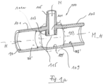
- Fig.1 shows the insert 100 according to the invention for a Fig.1 Blood tubing set 200 not shown (but see Fig.6 ) in a first exemplary embodiment in a longitudinal section.
- the insert piece 100 has a first connection point 101, by means of which a first hose section 205a (see Fig.6 ) of the blood tubing set 200 can be connected to the insert piece 100.
- the insert piece 100 has a second connection point 103, by means of which a second tube section 205b of the blood tube set 200 can be connected to the insert piece 100.
- the insert piece 100 has a third connection point 105, by means of which a third tube section, here a line for calcium solution 209 of the blood tubing set 200, can be connected to the insert piece 100.
- a third tube section here a line for calcium solution 209 of the blood tubing set 200
- the insert piece 100 has a main line 107 for conducting a first liquid, preferably blood, through the insert piece 100.
- the main line 107 is in fluid communication with the first connection point 101 and with the second connection point 103.
- the first liquid can flow into the main line 107 in the direction of the arrow H.
- the insert 100 has a longitudinal direction which is parallel to the center line of the main line 107, which is designated by the reference symbol M_H.
- the insert 100 has a transverse direction or radial direction, which is designated by r
- the insert 100 has an intermediate section 109.
- the main line 107 passes through it.
- the intermediate section 109 is in the Fig.1 by means of a dashed line.
- the insert piece 100 has a secondary line 111. It serves to guide a second liquid, preferably an infusion solution, into the main line 107.
- the second liquid can flow into the secondary line 111 in the direction of the arrow N.
- the secondary line 111 is in fluid communication with the third connection point 105. It is also in fluid communication with the main line 107 in the intermediate section 109 of the insert piece 100.
- the first connection point 101 has a flow-through lumen with a first cross-sectional area and an inner wall 101'.
- the inner wall 101' encloses an interior of the first connection point 101.
- the interior corresponds to its flow-through lumen.
- the second connection point 103 has a flow-through lumen with a second cross-sectional area and an inner wall 103'.
- the inner wall 103' encloses an interior of the second connection point 103.
- the interior corresponds to its flow-through lumen.
- the intermediate section 109 has a flow-through lumen with a third cross-sectional area and an inner wall 109'.
- the inner wall 109' encloses an interior of the intermediate section 109.
- the interior does not correspond to its flow-through lumen. Rather, the cross-sectional area of the interior is increased by the cross-sectional area of a lumen section 113, as far as this extends into the interior, larger than the permeable cross-sectional area of the lumen. If you imagine Fig.1 the lumen section 113 away, then in Fig.1 the interior corresponds to the permeable lumen.
- the center line of the main line 107 (approximately defined by the centers of the first and second cross-sectional areas, see above) is designated M_H.
- the center line M_H corresponds to the longitudinal axis of the main line 107 and its axial direction.
- the secondary line 111 has the lumen section 113, which projects into the interior of the intermediate section 109 and which has at least one mouth or outlet opening 115.
- the second liquid can be introduced into the lumen of the main line 107 through the outlet opening 115.
- the inner wall 101' encloses a flow-through lumen of the main line 107 in the region of the first connection point 101, while the inner wall 103' encloses a flow-through lumen of the main line 107 in the region of the second connection point 103.
- the inner wall 109 ⁇ encloses a flow-through lumen of the main line 107 in the region of the intermediate section 109.
- the lumen section 113 projects into the interior of the intermediate section 109.
- the lumen section 113 is not to be understood as a thickening or narrowing of the wall of the insert, but rather as an opening or continuation of the wall with the intention of moving the outlet opening 115 as far as possible radially into the flow-through interior of the main line 107 - and thus into the flow of the first liquid through the main line 107.
- the diameter of the exit opening 115 constitutes a large part of the diameter or cross-sectional area of the lumen portion 113, as described with reference to Fig.2 is further explained.
- the first connection point 101, the second connection point 103 and/or the third connection point 105 can optionally each have a bevel or chamfer 119 of the inner wall or the outer wall.
- the lumen section 113 is preferably not a section that corresponds to the inner wall 109' of the intermediate section 109 continuously. While the inner wall 109' delimits the interior of the intermediate section 109, the lumen section 113 projects beyond the inner wall 109' into the interior of the intermediate section 109.
- the lumen portion 113 is also not a structure that is annular in a cross-section of the intermediate portion 109.
- the lumen section 113 is not a diaphragm-shaped structure which forms a passage for the fluid in a cross-section of the intermediate section 109, but which would abut the inner wall 109 ⁇ in a circular manner on its outer circumference, i.e., for example, over the entire inner circumference of the intermediate section 109.
- the lumen section 113 is arranged inside the main line 107 such that liquid flowing through the lumen of the main line 107 can flow in the region of the lumen section 113 in front of it (i.e. in front of the drawing plane) as well as behind it (i.e. behind the drawing plane).
- the lumen section 113 protrudes into the interior of the main line 107 in a pin-shaped or cylindrical manner (e.g. with the center line M_N as the axis of rotation).
- An optional feature of the insert piece 100 according to the invention is that the flow-through area of the main line 107 in the area of the intermediate section 109 is not smaller than the flow-through area of the main line in the area of the first connection point 101 and/or in the area of the second connection point 103.
- Various embodiments are envisaged here according to the invention. One option is shown in Fig.1 shown; the inner wall of the intermediate section 109 is thinner compared to neighboring sections, which results in an increase in the flow-through lumen with a stepless outer wall.
- an offset of the wall of the main line 107 can be provided in the area of the intermediate section 109, such that the inner wall is offset radially outwards compared to neighboring areas, and that the outer wall is also offset radially outwards compared to neighboring areas.
- the latter is in Fig.1 not shown, the former, however, was.
- Fig. 1a shows the insert 100 according to the invention of the Fig.1 with a modification in the left branch of the main line 107.
- the inner wall 101 ⁇ of the main line 107 has a stop against which a Fig. 1a not shown hose, which is inserted into the first connection point 101, can be pushed.
- the ring-shaped stop 101a shown here as an example can be in contact with the front face of the hose, which is also ring-shaped and not shown, during use.
- the height of the stop 101a can advantageously be selected so that the inner wall of the hose is flush with the inner wall 101' of the section of the inner wall 109 ⁇ that adjoins the stop 101a to the right. In this way, the laminarity of the fluid in the stagnation area (near the wall) is not undesirably impaired.
- a stop 101a which can have the form of a step in the inner wall 101', is only shown on the left side of the insert piece 100. However, such a stop can also be provided in the area of the second connection point 103.
- Such a stop can also be provided in any other embodiment according to the invention.
- Such a stop can also be provided in any embodiment according to the invention together with a bevel or chamfer 119.
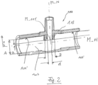
- Fig.2 shows the insert 100 according to the invention of the Fig.1 .
- Fig.2 on the reproduction of a variety of Fig.1 already known reference symbols have been omitted.
- the lumen section 113 projects into the interior of the intermediate section 109.
- the mouth or outlet opening 115 is clearly above the level of the inner wall 101' or 103' into the interior.
- the inner diameter of the main line 107 is A in the area of the first connection point 101 or in the area of the second connection point 103.
- the center point M_115 (or the geometric center of gravity) of an opening plane of the outlet opening 115 is located at a distance a from the center line M_H.
- the ratio a/A is preferably at most 0.33.
- the external diameter of the secondary line 111 in the area of the outlet opening 115 is the value D.
- the internal diameter of the secondary line 111 in the area of the outlet opening 115 is the value d.
- the ratio d/D is preferably at least 0.125.
- the ratio a/A is preferably at most 0.17, measured within a region whose points are at most 2*d away from a center line M_N of the secondary line 111.
- the second liquid can be introduced into the lumen of the main line 107 through the outlet opening 115.
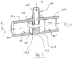
- Fig.3 shows the insert piece 100 according to the invention for a Fig.3 not shown blood tubing set 200 in a second exemplary embodiment in a longitudinal section.
- the lumen section 113 comprises portions which reach up to or extend to both opposite inner wall sections of the main line 107.
- an impact surface or deflection surface 113' is located opposite the outlet opening 115.
- the deflection surface 113' is part of the lumen section 113 or can be part of it.
- the deflection surface 113' can serve to ensure that the second liquid exiting from the outlet surface 115 is not discharged into radially outer flow areas ("stagnation areas") of the main line 107 when it exits the outlet surface 115, but rather enters the flow of the first liquid closer to the center line M_H, i.e. in an area of particularly high flow velocity.
- the design of the Fig.3 represents a more symmetrical design of the insert 100 in the area of the intermediate section 109 than that of the Fig.1 .
- With the design of the Fig.3 can help to keep the flow through the main line 107 as untouched as possible. In this way, the flow profile of the flow through the main line 107 can be left as unchanged as possible. This makes it easier to direct the second liquid in an area of highest flow velocity - relative to the first liquid in the main line 107 - into to introduce them, namely in a radially central area thereof.
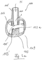
- Fig. 3a shows the insert 100 according to the invention of the Fig.3 in a cross-section.
- the flow through the main line 107 takes place in Fig. 3a mainly into or out of the drawing plane, i.e. perpendicular to the drawing plane.
- the impact surface or deflection surface 113' opposite the outlet opening 115 has a Fig.3 not visible groove 113a.
- the groove 113a is part of the lumen section 113 or can be part thereof. It preferably extends in the direction of flow through the main line 107 and is thus at least partially perpendicular to the plane of the drawing.
- the groove 113a can serve to ensure that the second liquid exiting the exit surface 115 is not discharged into radially outer flow regions ("stagnation regions") of the main line 107 when it exits the exit surface 115, but rather enters the flow of the first liquid closer to the center line M_H, i.e. in a region of particularly high flow velocity, and is guided in this over a predetermined distance due to the course of the groove 113a.
- the cross section of the groove 113a can be as in Fig. 3a shown by way of example, be triangular. Other cross-sectional shapes are also encompassed by the present invention.
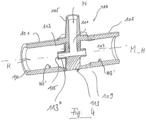
- Fig.4 shows the insert piece 100 according to the invention for a Fig.4 not shown blood tubing set 200 in a third exemplary embodiment in a longitudinal section.
- the lumen section 113 comprises, in addition to those parts that Fig.3 known, and a pipe section 113" aligned in the longitudinal direction of the main line 107.
- the pipe section 113" can have a round cross-sectional shape. Other, arbitrary cross-sectional shapes are also possible and are also encompassed by the present invention.
- the longitudinal axis of the pipe section 113" coincides with the longitudinal direction or here the center line M_H of the main line 107. In other embodiments, the longitudinal axis of the pipe section 113" or its longitudinal direction is parallel to the longitudinal direction or here the center line M_H of the main line 107.
- the deflection element 113" can advantageously serve to stabilize the flow. It can advantageously help to ensure that the second liquid is actually introduced in the middle of the flow profile across the cross section, or where the flow velocity within the main line 107 is at least sufficiently high or even highest.
- the pipe section 113" can help to ensure that the second liquid exits from the outlet opening 115 in an area in which the flow in the main line 107 does not stagnate.
- Fig.5 shows the insert piece 100 according to the invention for a Fig.3 not shown blood tubing set 200 in a fourth exemplary embodiment in a longitudinal section.
- the lumen section 113 comprises the tube section 113" of the Fig.4 . Unlike in Fig.4 however, the lumen section 113 does not extend through the entire interior of the intermediate section 109. The lumen section 113 therefore reduces the flow-through lumen of the intermediate section 109 less than in Fig.4 .
- Fig.6 shows an optional, basic arrangement of an insert piece 100 according to the invention in a schematically very simplified illustrated extracorporeal blood tubing set 200 according to the invention in an exemplary embodiment.
- the blood tubing set 200 includes or is connected to a hemofilter 201.
- a blood withdrawal line 203 (or arterial line) and a blood return line 205 (or venous line) are connected to the hemofilter 201, or dialyzer or blood filter.
- the blood collection line 203 is operatively connected to or has a blood pump 301.
- a line 207 for citrate solution flows into the blood withdrawal line 203.
- the line 207 is operatively connected to or has a citrate pump 307.
- the inventive line 209 for calcium solution opens into the blood return line 205.
- the insert 100 according to the invention is operatively connected to a calcium pump 309 or has this. It is made of a Fig.1 not shown source for an infusion solution, here as an example a calcium source.
- the source can be a bag or a bottle.
- the infusion solution can be produced online; in this case, the corresponding device in which the infusion solution is produced counts as the source.
- the operative connection with the calcium pump 309 is to be understood here as exemplary.
- the present invention also encompasses an arrangement of the insert piece 100 according to the invention behind a pump other than a calcium pump, for example downstream of a citrate pump such as the citrate pump 307 of the Fig.6 .
- the hemofilter 201 is connected to a line 311 for fresh dialysis fluid and a line 315 for used dialysate or filtrate.
- the line 311 is connected to or has a dialysis fluid pump 313.
- the line 315 is connected to or has a filtrate pump 317.
- the arrowheads shown indicate the direction of flow when the blood tubing set 200 is used as intended.
- the blood tubing set 200 shown may correspond to a conventional extracorporeal blood tubing set and may be particularly suitable for CWHD ( continuous veno-venous hemodialysis ).
- CWHD continuous veno-venous hemodialysis
- the pumps 301, 307, 309, 313 and 317 can be part of a blood treatment device 300, which is only indicated schematically. The same applies to the lines 311 and 315.
Landscapes
- Health & Medical Sciences (AREA)
- Heart & Thoracic Surgery (AREA)
- Vascular Medicine (AREA)
- Engineering & Computer Science (AREA)
- Anesthesiology (AREA)
- Biomedical Technology (AREA)
- Hematology (AREA)
- Life Sciences & Earth Sciences (AREA)
- Animal Behavior & Ethology (AREA)
- General Health & Medical Sciences (AREA)
- Public Health (AREA)
- Veterinary Medicine (AREA)
- Cardiology (AREA)
- External Artificial Organs (AREA)
Claims (15)
- Une pièce d'insertion (100) pour un set de tuyaux sanguins (200), comprenant au moins, respectivement:- un premier point de raccordement (101) pour raccorder une première section de tuyau (205a) du set de tuyaux sanguins (200) à la pièce d'insertion (100);- un second point de raccordement (103) pour raccorder une seconde section de tuyau (205b) du set de tuyaux sanguins (200) à la pièce d'insertion (100);- un troisième point de raccordement (105) pour raccorder une troisième section de tuyau (209) du set de tuyaux sanguins (200) à la pièce d'insertion (100);- un conduit principal (107) pour acheminer un premier liquide, de préférence du sang, au travers de la pièce d'insertion (100), le conduit principal (107) étant en communication fluidique avec le premier point de raccordement (101) ainsi qu'avec le second point de raccordement (103);- un conduit secondaire (111) pour acheminer un second liquide, de préférence une infusion, dans le conduit principal (107), le conduit secondaire (111) étant en communication fluidique avec le troisième point de raccordement (105), et le conduit secondaire (111) étant en outre en communication fluidique avec le conduit principal (107) dans une section intermédiaire (109) de la pièce d'insertion (100) agencée entre le premier point de raccordement (101) et le second point de raccordement (103);
où- le premier point de raccordement (101) comprend une lumière pouvant être traversée ayant une première de section transversale;- le second point de raccordement (103) comprend une lumière pouvant être traversée ayant une seconde section transversale;- la section intermédiaire (109) comprend une lumière pouvant être traversée ayant une troisième section transversale;caractérisée en ce que:- le conduit secondaire (111) comprend une section de lumière (113) qui fait saillie à l'intérieur de la section intermédiaire (109) et qui comprend au moins une embouchure ou un orifice de sortie (115) pour le second fluide; et- en ce qu'aucun obstacle à l'écoulement n'est présent à l'intérieur de la pièce d'insertion, à l'exception du conduit secondaire et/ou d'une chicane ou d'un élément déflecteur optionnel(le) (113') agencé (e) dans la zone de la section intermédiaire (109) pour limiter le second liquide s'écoulant de l'orifice de sortie ou de l'embouchure du conduit secondaire (111) dans son mouvement radial ou dans son mouvement allant dans le sens de sortie. - La pièce d'insertion (100) selon la première revendication, où la troisième section transversale est aussi grande, ou essentiellement aussi grande, que la première section transversale et/ou la seconde section transversale.
- La pièce d'insertion (100) selon l'une quelconque des revendications précédentes, où la section de lumière (113) est conçue pour délivrer le second liquide dans, ou essentiellement dans, le conduit principal (107), dans une direction axiale du conduit principal (107) ou parallèlement à une direction d'écoulement principale du conduit principal (107).
- La pièce d'insertion (100) selon l'une quelconque des revendications précédentes, où l'orifice de sortie (115) est agencé pour délivrer le second liquide dans, ou essentiellement dans, le conduit principal (107), dans une direction axiale du conduit principal (107) ou parallèlement à une direction d'écoulement principale du conduit principal (107).
- La pièce d'insertion (100) selon l'une quelconque des revendications précédentes, où une portion de la section de lumière (113) jouxtant en amont l'orifice de sortie (115) est agencée de telle sorte que sa direction longitudinale s'étend parallèlement, ou essentiellement parallèlement, à l'axe longitudinal de la section intermédiaire (109).
- La pièce d'insertion (100) selon l'une quelconque des revendications précédentes, où une chicane ou un élément déflecteur (113') est agencé(e) à l'intérieur de la section intermédiaire (109) dans la zone de la section intermédiaire (109), de telle sorte qu'un second liquide s'écoulant de l'orifice de sortie (115) ou de l'embouchure du conduit secondaire (111) est limité dans son mouvement radial.
- La pièce d'insertion (100) selon l'une quelconque des revendications précédentes, où la section de lumière (113) s'étend, en une seule pièce ou en plusieurs pièces, au travers de tout l'intérieur de la section intermédiaire (109) ou du conduit principal (107) dans une direction radiale (r).
- La pièce d'insertion (100) selon l'une quelconque des revendications précédentes, où la section de lumière (113) comprend au moins une rainure (113a) qui s'étend, au moins par portions, dans une direction parallèle au conduit principal (107).
- La pièce d'insertion (100) selon l'une quelconque des revendications précédentes, où une saillie s'étend à l'intérieur de la section intermédiaire (109) dans la zone de la section intermédiaire (109), laquelle saillie se situe dans un prolongement du conduit secondaire (111) dans la section intermédiaire (109).
- Un set de tuyaux sanguins (200) ou un circuit sanguin extracorporel (200), qui comprend au moins une pièce d'insertion (100) selon l'une quelconque des revendications précédentes.
- Le set de tuyaux sanguins (200) selon la revendication 10, où la pièce d'insertion (100) est reliée en communication fluidique avec un conduit d'addition (207, 209) et en communication fluidique avec un conduit de prélèvement sanguin (203) et/ou un conduit de retour sanguin (205).
- Le set de tuyaux sanguins (200) selon l'une quelconque des revendications 10 et 11, où le set de tuyaux sanguins (200) est adapté et/ou préparé pour réaliser une anticoagulation régionale.
- Le set de tuyaux sanguins (200) selon l'une quelconque des revendications 10 à 12, où le set de tuyaux sanguins (200) est adapté pour réaliser une hémodialyse, une hémofiltration, une hémodiaflitration, un traitement par plasmaphérèse ou un traitement par adsorption de sang total.
- Le set de tuyaux sanguins (200) selon l'une quelconque des revendications 10 à 13, ou le premier point de raccordement (101) et le second point de raccordement (103) sont reliés à un conduit d'acheminement du sang du set de tuyaux sanguins (200) et où le troisième point de raccordement (105) est relié à un conduit pour une solution électrolytique, notamment un conduit de calcium.
- Un appareil de traitement du sang (300) relié à au moins un set de tuyaux sanguins (200) selon l'une quelconque des revendications 10 à 14.
Applications Claiming Priority (2)
| Application Number | Priority Date | Filing Date | Title |
|---|---|---|---|
| DE102016117974.4A DE102016117974A1 (de) | 2016-09-23 | 2016-09-23 | Einsatzstück für einen Blutschlauchsatz zum Begünstigen einer Vermischung einer Infusionslösung mit einem weiteren Fluid |
| PCT/EP2017/074043 WO2018055091A1 (fr) | 2016-09-23 | 2017-09-22 | Insert pour un ensemble de tubulures sanguines permettant de faciliter un mélange d'une solution d'infusion avec un autre liquide |
Publications (2)
| Publication Number | Publication Date |
|---|---|
| EP3515529A1 EP3515529A1 (fr) | 2019-07-31 |
| EP3515529B1 true EP3515529B1 (fr) | 2024-07-24 |
Family
ID=59982365
Family Applications (1)
| Application Number | Title | Priority Date | Filing Date |
|---|---|---|---|
| EP17777230.8A Active EP3515529B1 (fr) | 2016-09-23 | 2017-09-22 | Insert pour un ensemble de tubulures sanguines permettant de faciliter un mélange d'une solution d'infusion avec un autre liquide |
Country Status (5)
| Country | Link |
|---|---|
| US (1) | US11918722B2 (fr) |
| EP (1) | EP3515529B1 (fr) |
| CN (1) | CN109789261B (fr) |
| DE (1) | DE102016117974A1 (fr) |
| WO (1) | WO2018055091A1 (fr) |
Families Citing this family (4)
| Publication number | Priority date | Publication date | Assignee | Title |
|---|---|---|---|---|
| EP3421061A1 (fr) | 2017-06-28 | 2019-01-02 | Fresenius Medical Care Deutschland GmbH | Autre élément d'insert pour un ensemble de tubulures pour le sang afin de favoriser le mélange d'une solution de perfusion avec un autre fluide |
| DE102020116247A1 (de) * | 2020-06-19 | 2021-12-23 | Fresenius Medical Care Deutschland Gmbh | Schlaucheinsatzstück für einen hydraulikschlauchsatz einer blutbehandlungsvorrichtung |
| EP4088758A1 (fr) * | 2021-05-12 | 2022-11-16 | Fresenius Medical Care Deutschland GmbH | Site de perfusion d'un système de tubulures sanguines |
| US20250032747A1 (en) * | 2023-07-28 | 2025-01-30 | Philip Meyers | Multi-Component Medical Packaging Device |
Family Cites Families (15)
| Publication number | Priority date | Publication date | Assignee | Title |
|---|---|---|---|---|
| US3511238A (en) | 1967-04-14 | 1970-05-12 | Bio Medical Systems Inc | System for transferring human fluids without clotting thereof |
| SE458340B (sv) | 1984-06-18 | 1989-03-20 | Gambro Lundia Ab | Blodfiltreringssystem samt dropp- och /eller expansionskammare avsedd foer detta system |
| JPH043060Y2 (fr) * | 1986-08-28 | 1992-01-31 | ||
| IT1250529B (it) * | 1991-12-13 | 1995-04-08 | Hospal Dasco Spa | Raccordo di campionamento e di infusione per una linea di circolazione extracorporea di sangue. |
| DE4240681C2 (de) | 1992-12-03 | 1994-09-08 | Fresenius Ag | Vorrichtung zur Hämodialyse ohne Antikoagulation |
| US7615028B2 (en) | 2004-12-03 | 2009-11-10 | Chf Solutions Inc. | Extracorporeal blood treatment and system having reversible blood pumps |
| CA2643140C (fr) | 2006-02-22 | 2014-12-09 | Henry Ford Health System | Systeme et procede pour l'administration d'anticoagulation regionale au citrate a des circuits sanguins extracorporels |
| FR2920314B1 (fr) | 2007-09-05 | 2010-07-30 | Gambro Lundia Ab | Circuit de traitement extracorporel de sang et ligne ayant un site d'infusion pour le melange optimise de fluides |
| DE102010047747B4 (de) | 2010-10-08 | 2017-11-02 | Cedic Srl-Divisione Biomedicale | Einwegeventil für ein Infusionsbesteck |
| DE102011108784A1 (de) | 2011-07-29 | 2013-01-31 | Fresenius Medical Care Deutschland Gmbh | Verfahren sowie Vorrichtungen zum Überprüfen wenigstens einer Funktion einer medizinischen Funktionseinrichtung |
| DE102011116262A1 (de) | 2011-10-19 | 2013-04-25 | Fresenius Medical Care Deutschland Gmbh | Verfahren sowie Vorrichtungen zum retrograden Befüllen wenigstens einer Calciumleitung eines extrakorporalen Blutkreislaufs |
| DE102012016210A1 (de) | 2012-08-16 | 2014-02-20 | Fresenius Medical Care Deutschland Gmbh | T-Stück rnit Turbulenzerzeugung |
| DE102013011010A1 (de) | 2013-07-02 | 2015-01-22 | Fresenius Medical Care Deutschland Gmbh | Verfahren und Vorrichtung zur Turbulenzerzeugung durch pulsierenden Fluss |
| JP5826815B2 (ja) * | 2013-12-11 | 2015-12-02 | 日機装株式会社 | 混注部材 |
| DE102015008143A1 (de) | 2015-06-24 | 2016-12-29 | Fresenius Medical Care Deutschland Gmbh | Adapter |
-
2016
- 2016-09-23 DE DE102016117974.4A patent/DE102016117974A1/de not_active Ceased
-
2017
- 2017-09-22 EP EP17777230.8A patent/EP3515529B1/fr active Active
- 2017-09-22 WO PCT/EP2017/074043 patent/WO2018055091A1/fr not_active Ceased
- 2017-09-22 US US16/335,304 patent/US11918722B2/en active Active
- 2017-09-22 CN CN201780059035.4A patent/CN109789261B/zh active Active
Also Published As
| Publication number | Publication date |
|---|---|
| US20200016314A1 (en) | 2020-01-16 |
| WO2018055091A1 (fr) | 2018-03-29 |
| CN109789261A (zh) | 2019-05-21 |
| DE102016117974A1 (de) | 2018-03-29 |
| US11918722B2 (en) | 2024-03-05 |
| EP3515529A1 (fr) | 2019-07-31 |
| CN109789261B (zh) | 2022-03-08 |
Similar Documents
| Publication | Publication Date | Title |
|---|---|---|
| EP3515529B1 (fr) | Insert pour un ensemble de tubulures sanguines permettant de faciliter un mélange d'une solution d'infusion avec un autre liquide | |
| DE2645520C2 (fr) | ||
| DE69636325T2 (de) | Kegelförmiger verstärkter Katheter | |
| EP0150462B1 (fr) | Cathéter à deux canaux séparés pour un dispositif de purification de sang | |
| WO2018109071A1 (fr) | Dispositif de traitement de sang destiné à effectuer un traitement de sang extracorporel, dispositif de conduite de sang, système de traitement de sang | |
| EP2885020B1 (fr) | Pièce en t produisant des turbulences | |
| EP2015797A2 (fr) | Procédé de remplissage et de rinçage d'un ensemble de tuyaux pour le sang | |
| DE102016117725A1 (de) | Verfahren zum Entfernen von Blut aus einem extrakorporalen Blutkreislauf nach Beendigung einer Blutbehandlungssitzung, Steuerungs- und Regelungseinrichtung sowie Behandlungsvorrichtung zum Durchführen desselben | |
| EP2654823B1 (fr) | Chambre pour un circuit de traitement de sang d'un circuit de sang extracorporel d'une machine de dialyse , utilisation de la chambre, système de flexible pour sang et système de traitement de sang | |
| WO2013010666A1 (fr) | Module de filtrage | |
| DE102010032181A1 (de) | Ankoppeleinrichtung, Konnektor, medizintechnische Funktionseinrichtung, medizintechnische Behandlungsvorrichtung sowie Verfahren | |
| EP2954911B1 (fr) | Pompe de liquide de substitution intégrée dans une machine de dialyse | |
| DE102011015075B4 (de) | Blutschlauchabschnitt zum extrakorporalen Führen von Blut, extrakorporaler Blutkreislauf, Behandlungsvorrichtung sowie Verfahren | |
| EP4168095A1 (fr) | Pièce d'insertion de tuyau conçue pour un ensemble tuyau hydraulique d'un dispositif de traitement sanguin | |
| EP3934711B1 (fr) | Ensemble de conduits sanguins et machine de traitement sanguin extracorporels | |
| EP3237036B1 (fr) | Ligne de perfusion avec dispositif pour favoriser le mélange d'une solution de perfusion avec un autre fluide | |
| EP3773791B1 (fr) | Dispositif de commande ou de réglage et dispositif de traitement de sang pour un traitement à aiguille unique | |
| EP3421061A1 (fr) | Autre élément d'insert pour un ensemble de tubulures pour le sang afin de favoriser le mélange d'une solution de perfusion avec un autre fluide | |
| EP3513867B1 (fr) | Machine de traitement du sang dotée d'un module filtrant à fibres creuses destiné à l'agencement horizontal | |
| EP3996769B1 (fr) | Machine de dialyse avec deux chambres d'équilibre qui sont en communication fluidique l'une avec l'autre | |
| EP3150273A1 (fr) | Module de filtre d'une machine de traitement du sang extracorporelle | |
| EP2112936B1 (fr) | Dispositif et procédé de filtration d'un mélange composé d'un constituant sanguin et d'une solution additive | |
| EP3996768A1 (fr) | Appareil de dialyse à trois chambres d'équilibrage | |
| EP4337372A1 (fr) | Filtre à membranes à fibres creuses présentant des propriétés de séparation améliorées | |
| DE102023121091A1 (de) | Multiplex-Infusionssystem mit Steuervorrichtung, Katheter und Speichereinheit für ein solches Multiplex-Infusionssystem |
Legal Events
| Date | Code | Title | Description |
|---|---|---|---|
| STAA | Information on the status of an ep patent application or granted ep patent |
Free format text: STATUS: UNKNOWN |
|
| STAA | Information on the status of an ep patent application or granted ep patent |
Free format text: STATUS: THE INTERNATIONAL PUBLICATION HAS BEEN MADE |
|
| PUAI | Public reference made under article 153(3) epc to a published international application that has entered the european phase |
Free format text: ORIGINAL CODE: 0009012 |
|
| STAA | Information on the status of an ep patent application or granted ep patent |
Free format text: STATUS: REQUEST FOR EXAMINATION WAS MADE |
|
| 17P | Request for examination filed |
Effective date: 20190423 |
|
| AK | Designated contracting states |
Kind code of ref document: A1 Designated state(s): AL AT BE BG CH CY CZ DE DK EE ES FI FR GB GR HR HU IE IS IT LI LT LU LV MC MK MT NL NO PL PT RO RS SE SI SK SM TR |
|
| AX | Request for extension of the european patent |
Extension state: BA ME |
|
| DAV | Request for validation of the european patent (deleted) | ||
| DAX | Request for extension of the european patent (deleted) | ||
| STAA | Information on the status of an ep patent application or granted ep patent |
Free format text: STATUS: EXAMINATION IS IN PROGRESS |
|
| 17Q | First examination report despatched |
Effective date: 20200511 |
|
| 17Q | First examination report despatched |
Effective date: 20200526 |
|
| GRAP | Despatch of communication of intention to grant a patent |
Free format text: ORIGINAL CODE: EPIDOSNIGR1 |
|
| STAA | Information on the status of an ep patent application or granted ep patent |
Free format text: STATUS: GRANT OF PATENT IS INTENDED |
|
| INTG | Intention to grant announced |
Effective date: 20231004 |
|
| P01 | Opt-out of the competence of the unified patent court (upc) registered |
Effective date: 20231128 |
|
| GRAJ | Information related to disapproval of communication of intention to grant by the applicant or resumption of examination proceedings by the epo deleted |
Free format text: ORIGINAL CODE: EPIDOSDIGR1 |
|
| STAA | Information on the status of an ep patent application or granted ep patent |
Free format text: STATUS: EXAMINATION IS IN PROGRESS |
|
| GRAS | Grant fee paid |
Free format text: ORIGINAL CODE: EPIDOSNIGR3 |
|
| STAA | Information on the status of an ep patent application or granted ep patent |
Free format text: STATUS: GRANT OF PATENT IS INTENDED |
|
| GRAP | Despatch of communication of intention to grant a patent |
Free format text: ORIGINAL CODE: EPIDOSNIGR1 |
|
| INTC | Intention to grant announced (deleted) | ||
| INTG | Intention to grant announced |
Effective date: 20240222 |
|
| GRAA | (expected) grant |
Free format text: ORIGINAL CODE: 0009210 |
|
| STAA | Information on the status of an ep patent application or granted ep patent |
Free format text: STATUS: THE PATENT HAS BEEN GRANTED |
|
| AK | Designated contracting states |
Kind code of ref document: B1 Designated state(s): AL AT BE BG CH CY CZ DE DK EE ES FI FR GB GR HR HU IE IS IT LI LT LU LV MC MK MT NL NO PL PT RO RS SE SI SK SM TR |
|
| REG | Reference to a national code |
Ref country code: GB Ref legal event code: FG4D Free format text: NOT ENGLISH |
|
| REG | Reference to a national code |
Ref country code: CH Ref legal event code: EP |
|
| REG | Reference to a national code |
Ref country code: IE Ref legal event code: FG4D Free format text: LANGUAGE OF EP DOCUMENT: GERMAN Ref country code: DE Ref legal event code: R096 Ref document number: 502017016288 Country of ref document: DE |
|
| REG | Reference to a national code |
Ref country code: LT Ref legal event code: MG9D |
|
| REG | Reference to a national code |
Ref country code: NL Ref legal event code: MP Effective date: 20240724 |
|
| PG25 | Lapsed in a contracting state [announced via postgrant information from national office to epo] |
Ref country code: PT Free format text: LAPSE BECAUSE OF FAILURE TO SUBMIT A TRANSLATION OF THE DESCRIPTION OR TO PAY THE FEE WITHIN THE PRESCRIBED TIME-LIMIT Effective date: 20241125 |
|
| PG25 | Lapsed in a contracting state [announced via postgrant information from national office to epo] |
Ref country code: NL Free format text: LAPSE BECAUSE OF FAILURE TO SUBMIT A TRANSLATION OF THE DESCRIPTION OR TO PAY THE FEE WITHIN THE PRESCRIBED TIME-LIMIT Effective date: 20240724 |
|
| PG25 | Lapsed in a contracting state [announced via postgrant information from national office to epo] |
Ref country code: PT Free format text: LAPSE BECAUSE OF FAILURE TO SUBMIT A TRANSLATION OF THE DESCRIPTION OR TO PAY THE FEE WITHIN THE PRESCRIBED TIME-LIMIT Effective date: 20241125 Ref country code: NL Free format text: LAPSE BECAUSE OF FAILURE TO SUBMIT A TRANSLATION OF THE DESCRIPTION OR TO PAY THE FEE WITHIN THE PRESCRIBED TIME-LIMIT Effective date: 20240724 |
|
| PG25 | Lapsed in a contracting state [announced via postgrant information from national office to epo] |
Ref country code: NO Free format text: LAPSE BECAUSE OF FAILURE TO SUBMIT A TRANSLATION OF THE DESCRIPTION OR TO PAY THE FEE WITHIN THE PRESCRIBED TIME-LIMIT Effective date: 20241024 |
|
| PG25 | Lapsed in a contracting state [announced via postgrant information from national office to epo] |
Ref country code: PL Free format text: LAPSE BECAUSE OF FAILURE TO SUBMIT A TRANSLATION OF THE DESCRIPTION OR TO PAY THE FEE WITHIN THE PRESCRIBED TIME-LIMIT Effective date: 20240724 Ref country code: FI Free format text: LAPSE BECAUSE OF FAILURE TO SUBMIT A TRANSLATION OF THE DESCRIPTION OR TO PAY THE FEE WITHIN THE PRESCRIBED TIME-LIMIT Effective date: 20240724 Ref country code: GR Free format text: LAPSE BECAUSE OF FAILURE TO SUBMIT A TRANSLATION OF THE DESCRIPTION OR TO PAY THE FEE WITHIN THE PRESCRIBED TIME-LIMIT Effective date: 20241025 |
|
| PG25 | Lapsed in a contracting state [announced via postgrant information from national office to epo] |
Ref country code: BG Free format text: LAPSE BECAUSE OF FAILURE TO SUBMIT A TRANSLATION OF THE DESCRIPTION OR TO PAY THE FEE WITHIN THE PRESCRIBED TIME-LIMIT Effective date: 20240724 |
|
| PG25 | Lapsed in a contracting state [announced via postgrant information from national office to epo] |
Ref country code: LV Free format text: LAPSE BECAUSE OF FAILURE TO SUBMIT A TRANSLATION OF THE DESCRIPTION OR TO PAY THE FEE WITHIN THE PRESCRIBED TIME-LIMIT Effective date: 20240724 |
|
| PG25 | Lapsed in a contracting state [announced via postgrant information from national office to epo] |
Ref country code: IS Free format text: LAPSE BECAUSE OF FAILURE TO SUBMIT A TRANSLATION OF THE DESCRIPTION OR TO PAY THE FEE WITHIN THE PRESCRIBED TIME-LIMIT Effective date: 20241124 |
|
| PG25 | Lapsed in a contracting state [announced via postgrant information from national office to epo] |
Ref country code: HR Free format text: LAPSE BECAUSE OF FAILURE TO SUBMIT A TRANSLATION OF THE DESCRIPTION OR TO PAY THE FEE WITHIN THE PRESCRIBED TIME-LIMIT Effective date: 20240724 |
|
| PG25 | Lapsed in a contracting state [announced via postgrant information from national office to epo] |
Ref country code: RS Free format text: LAPSE BECAUSE OF FAILURE TO SUBMIT A TRANSLATION OF THE DESCRIPTION OR TO PAY THE FEE WITHIN THE PRESCRIBED TIME-LIMIT Effective date: 20241024 Ref country code: ES Free format text: LAPSE BECAUSE OF FAILURE TO SUBMIT A TRANSLATION OF THE DESCRIPTION OR TO PAY THE FEE WITHIN THE PRESCRIBED TIME-LIMIT Effective date: 20240724 |
|
| PG25 | Lapsed in a contracting state [announced via postgrant information from national office to epo] |
Ref country code: RS Free format text: LAPSE BECAUSE OF FAILURE TO SUBMIT A TRANSLATION OF THE DESCRIPTION OR TO PAY THE FEE WITHIN THE PRESCRIBED TIME-LIMIT Effective date: 20241024 Ref country code: PL Free format text: LAPSE BECAUSE OF FAILURE TO SUBMIT A TRANSLATION OF THE DESCRIPTION OR TO PAY THE FEE WITHIN THE PRESCRIBED TIME-LIMIT Effective date: 20240724 Ref country code: NO Free format text: LAPSE BECAUSE OF FAILURE TO SUBMIT A TRANSLATION OF THE DESCRIPTION OR TO PAY THE FEE WITHIN THE PRESCRIBED TIME-LIMIT Effective date: 20241024 Ref country code: LV Free format text: LAPSE BECAUSE OF FAILURE TO SUBMIT A TRANSLATION OF THE DESCRIPTION OR TO PAY THE FEE WITHIN THE PRESCRIBED TIME-LIMIT Effective date: 20240724 Ref country code: IS Free format text: LAPSE BECAUSE OF FAILURE TO SUBMIT A TRANSLATION OF THE DESCRIPTION OR TO PAY THE FEE WITHIN THE PRESCRIBED TIME-LIMIT Effective date: 20241124 Ref country code: HR Free format text: LAPSE BECAUSE OF FAILURE TO SUBMIT A TRANSLATION OF THE DESCRIPTION OR TO PAY THE FEE WITHIN THE PRESCRIBED TIME-LIMIT Effective date: 20240724 Ref country code: GR Free format text: LAPSE BECAUSE OF FAILURE TO SUBMIT A TRANSLATION OF THE DESCRIPTION OR TO PAY THE FEE WITHIN THE PRESCRIBED TIME-LIMIT Effective date: 20241025 Ref country code: FI Free format text: LAPSE BECAUSE OF FAILURE TO SUBMIT A TRANSLATION OF THE DESCRIPTION OR TO PAY THE FEE WITHIN THE PRESCRIBED TIME-LIMIT Effective date: 20240724 Ref country code: ES Free format text: LAPSE BECAUSE OF FAILURE TO SUBMIT A TRANSLATION OF THE DESCRIPTION OR TO PAY THE FEE WITHIN THE PRESCRIBED TIME-LIMIT Effective date: 20240724 Ref country code: BG Free format text: LAPSE BECAUSE OF FAILURE TO SUBMIT A TRANSLATION OF THE DESCRIPTION OR TO PAY THE FEE WITHIN THE PRESCRIBED TIME-LIMIT Effective date: 20240724 |
|
| PG25 | Lapsed in a contracting state [announced via postgrant information from national office to epo] |
Ref country code: SM Free format text: LAPSE BECAUSE OF FAILURE TO SUBMIT A TRANSLATION OF THE DESCRIPTION OR TO PAY THE FEE WITHIN THE PRESCRIBED TIME-LIMIT Effective date: 20240724 Ref country code: DK Free format text: LAPSE BECAUSE OF FAILURE TO SUBMIT A TRANSLATION OF THE DESCRIPTION OR TO PAY THE FEE WITHIN THE PRESCRIBED TIME-LIMIT Effective date: 20240724 Ref country code: RO Free format text: LAPSE BECAUSE OF FAILURE TO SUBMIT A TRANSLATION OF THE DESCRIPTION OR TO PAY THE FEE WITHIN THE PRESCRIBED TIME-LIMIT Effective date: 20240724 |
|
| PG25 | Lapsed in a contracting state [announced via postgrant information from national office to epo] |
Ref country code: MC Free format text: LAPSE BECAUSE OF FAILURE TO SUBMIT A TRANSLATION OF THE DESCRIPTION OR TO PAY THE FEE WITHIN THE PRESCRIBED TIME-LIMIT Effective date: 20240724 Ref country code: EE Free format text: LAPSE BECAUSE OF FAILURE TO SUBMIT A TRANSLATION OF THE DESCRIPTION OR TO PAY THE FEE WITHIN THE PRESCRIBED TIME-LIMIT Effective date: 20240724 |
|
| PG25 | Lapsed in a contracting state [announced via postgrant information from national office to epo] |
Ref country code: CZ Free format text: LAPSE BECAUSE OF FAILURE TO SUBMIT A TRANSLATION OF THE DESCRIPTION OR TO PAY THE FEE WITHIN THE PRESCRIBED TIME-LIMIT Effective date: 20240724 |
|
| REG | Reference to a national code |
Ref country code: DE Ref legal event code: R097 Ref document number: 502017016288 Country of ref document: DE |
|
| PG25 | Lapsed in a contracting state [announced via postgrant information from national office to epo] |
Ref country code: SK Free format text: LAPSE BECAUSE OF FAILURE TO SUBMIT A TRANSLATION OF THE DESCRIPTION OR TO PAY THE FEE WITHIN THE PRESCRIBED TIME-LIMIT Effective date: 20240724 |
|
| REG | Reference to a national code |
Ref country code: CH Ref legal event code: PL |
|
| PG25 | Lapsed in a contracting state [announced via postgrant information from national office to epo] |
Ref country code: LU Free format text: LAPSE BECAUSE OF NON-PAYMENT OF DUE FEES Effective date: 20240922 |
|
| PLBE | No opposition filed within time limit |
Free format text: ORIGINAL CODE: 0009261 |
|
| STAA | Information on the status of an ep patent application or granted ep patent |
Free format text: STATUS: NO OPPOSITION FILED WITHIN TIME LIMIT |
|
| 26N | No opposition filed |
Effective date: 20250425 |
|
| REG | Reference to a national code |
Ref country code: BE Ref legal event code: MM Effective date: 20240930 |
|
| PG25 | Lapsed in a contracting state [announced via postgrant information from national office to epo] |
Ref country code: BE Free format text: LAPSE BECAUSE OF NON-PAYMENT OF DUE FEES Effective date: 20240930 |
|
| PG25 | Lapsed in a contracting state [announced via postgrant information from national office to epo] |
Ref country code: CH Free format text: LAPSE BECAUSE OF NON-PAYMENT OF DUE FEES Effective date: 20240930 |
|
| PG25 | Lapsed in a contracting state [announced via postgrant information from national office to epo] |
Ref country code: IE Free format text: LAPSE BECAUSE OF NON-PAYMENT OF DUE FEES Effective date: 20240922 |
|
| PG25 | Lapsed in a contracting state [announced via postgrant information from national office to epo] |
Ref country code: SE Free format text: LAPSE BECAUSE OF FAILURE TO SUBMIT A TRANSLATION OF THE DESCRIPTION OR TO PAY THE FEE WITHIN THE PRESCRIBED TIME-LIMIT Effective date: 20240724 |
|
| PGFP | Annual fee paid to national office [announced via postgrant information from national office to epo] |
Ref country code: DE Payment date: 20250820 Year of fee payment: 9 |
|
| PGFP | Annual fee paid to national office [announced via postgrant information from national office to epo] |
Ref country code: IT Payment date: 20250820 Year of fee payment: 9 |
|
| PGFP | Annual fee paid to national office [announced via postgrant information from national office to epo] |
Ref country code: GB Payment date: 20250822 Year of fee payment: 9 |
|
| PGFP | Annual fee paid to national office [announced via postgrant information from national office to epo] |
Ref country code: FR Payment date: 20250821 Year of fee payment: 9 |
|
| REG | Reference to a national code |
Ref country code: AT Ref legal event code: MM01 Ref document number: 1705716 Country of ref document: AT Kind code of ref document: T Effective date: 20240922 |
|
| PG25 | Lapsed in a contracting state [announced via postgrant information from national office to epo] |
Ref country code: AT Free format text: LAPSE BECAUSE OF NON-PAYMENT OF DUE FEES Effective date: 20240922 |
|
| PG25 | Lapsed in a contracting state [announced via postgrant information from national office to epo] |
Ref country code: CY Free format text: LAPSE BECAUSE OF FAILURE TO SUBMIT A TRANSLATION OF THE DESCRIPTION OR TO PAY THE FEE WITHIN THE PRESCRIBED TIME-LIMIT; INVALID AB INITIO Effective date: 20170922 |
|
| PG25 | Lapsed in a contracting state [announced via postgrant information from national office to epo] |
Ref country code: HU Free format text: LAPSE BECAUSE OF FAILURE TO SUBMIT A TRANSLATION OF THE DESCRIPTION OR TO PAY THE FEE WITHIN THE PRESCRIBED TIME-LIMIT; INVALID AB INITIO Effective date: 20170922 |