EP3515768B1 - Systeme de freinage par manque de courant - Google Patents
Systeme de freinage par manque de courant Download PDFInfo
- Publication number
- EP3515768B1 EP3515768B1 EP17772454.9A EP17772454A EP3515768B1 EP 3515768 B1 EP3515768 B1 EP 3515768B1 EP 17772454 A EP17772454 A EP 17772454A EP 3515768 B1 EP3515768 B1 EP 3515768B1
- Authority
- EP
- European Patent Office
- Prior art keywords
- brake
- application system
- arm
- electromagnet
- power
- Prior art date
- Legal status (The legal status is an assumption and is not a legal conclusion. Google has not performed a legal analysis and makes no representation as to the accuracy of the status listed.)
- Active
Links
Images


Classifications
-
- F—MECHANICAL ENGINEERING; LIGHTING; HEATING; WEAPONS; BLASTING
- F16—ENGINEERING ELEMENTS AND UNITS; GENERAL MEASURES FOR PRODUCING AND MAINTAINING EFFECTIVE FUNCTIONING OF MACHINES OR INSTALLATIONS; THERMAL INSULATION IN GENERAL
- F16D—COUPLINGS FOR TRANSMITTING ROTATION; CLUTCHES; BRAKES
- F16D65/00—Parts or details
- F16D65/14—Actuating mechanisms for brakes; Means for initiating operation at a predetermined position
- F16D65/16—Actuating mechanisms for brakes; Means for initiating operation at a predetermined position arranged in or on the brake
- F16D65/18—Actuating mechanisms for brakes; Means for initiating operation at a predetermined position arranged in or on the brake adapted for drawing members together, e.g. for disc brakes
-
- B—PERFORMING OPERATIONS; TRANSPORTING
- B60—VEHICLES IN GENERAL
- B60T—VEHICLE BRAKE CONTROL SYSTEMS OR PARTS THEREOF; BRAKE CONTROL SYSTEMS OR PARTS THEREOF, IN GENERAL; ARRANGEMENT OF BRAKING ELEMENTS ON VEHICLES IN GENERAL; PORTABLE DEVICES FOR PREVENTING UNWANTED MOVEMENT OF VEHICLES; VEHICLE MODIFICATIONS TO FACILITATE COOLING OF BRAKES
- B60T1/00—Arrangements of braking elements, i.e. of those parts where braking effect occurs specially for vehicles
- B60T1/02—Arrangements of braking elements, i.e. of those parts where braking effect occurs specially for vehicles acting by retarding wheels
- B60T1/10—Arrangements of braking elements, i.e. of those parts where braking effect occurs specially for vehicles acting by retarding wheels by utilising wheel movement for accumulating energy, e.g. driving air compressors
-
- B—PERFORMING OPERATIONS; TRANSPORTING
- B60—VEHICLES IN GENERAL
- B60T—VEHICLE BRAKE CONTROL SYSTEMS OR PARTS THEREOF; BRAKE CONTROL SYSTEMS OR PARTS THEREOF, IN GENERAL; ARRANGEMENT OF BRAKING ELEMENTS ON VEHICLES IN GENERAL; PORTABLE DEVICES FOR PREVENTING UNWANTED MOVEMENT OF VEHICLES; VEHICLE MODIFICATIONS TO FACILITATE COOLING OF BRAKES
- B60T13/00—Transmitting braking action from initiating means to ultimate brake actuator with power assistance or drive; Brake systems incorporating such transmitting means, e.g. air-pressure brake systems
- B60T13/02—Transmitting braking action from initiating means to ultimate brake actuator with power assistance or drive; Brake systems incorporating such transmitting means, e.g. air-pressure brake systems with mechanical assistance or drive
- B60T13/04—Transmitting braking action from initiating means to ultimate brake actuator with power assistance or drive; Brake systems incorporating such transmitting means, e.g. air-pressure brake systems with mechanical assistance or drive by spring or weight
-
- B—PERFORMING OPERATIONS; TRANSPORTING
- B60—VEHICLES IN GENERAL
- B60T—VEHICLE BRAKE CONTROL SYSTEMS OR PARTS THEREOF; BRAKE CONTROL SYSTEMS OR PARTS THEREOF, IN GENERAL; ARRANGEMENT OF BRAKING ELEMENTS ON VEHICLES IN GENERAL; PORTABLE DEVICES FOR PREVENTING UNWANTED MOVEMENT OF VEHICLES; VEHICLE MODIFICATIONS TO FACILITATE COOLING OF BRAKES
- B60T7/00—Brake-action initiating means
- B60T7/12—Brake-action initiating means for automatic initiation; for initiation not subject to will of driver or passenger
-
- F—MECHANICAL ENGINEERING; LIGHTING; HEATING; WEAPONS; BLASTING
- F16—ENGINEERING ELEMENTS AND UNITS; GENERAL MEASURES FOR PRODUCING AND MAINTAINING EFFECTIVE FUNCTIONING OF MACHINES OR INSTALLATIONS; THERMAL INSULATION IN GENERAL
- F16D—COUPLINGS FOR TRANSMITTING ROTATION; CLUTCHES; BRAKES
- F16D55/00—Brakes with substantially-radial braking surfaces pressed together in axial direction, e.g. disc brakes
- F16D55/02—Brakes with substantially-radial braking surfaces pressed together in axial direction, e.g. disc brakes with axially-movable discs or pads pressed against axially-located rotating members
- F16D55/22—Brakes with substantially-radial braking surfaces pressed together in axial direction, e.g. disc brakes with axially-movable discs or pads pressed against axially-located rotating members by clamping an axially-located rotating disc between movable braking members, e.g. movable brake discs or brake pads
- F16D55/224—Brakes with substantially-radial braking surfaces pressed together in axial direction, e.g. disc brakes with axially-movable discs or pads pressed against axially-located rotating members by clamping an axially-located rotating disc between movable braking members, e.g. movable brake discs or brake pads with a common actuating member for the braking members
- F16D55/225—Brakes with substantially-radial braking surfaces pressed together in axial direction, e.g. disc brakes with axially-movable discs or pads pressed against axially-located rotating members by clamping an axially-located rotating disc between movable braking members, e.g. movable brake discs or brake pads with a common actuating member for the braking members the braking members being brake pads
-
- F—MECHANICAL ENGINEERING; LIGHTING; HEATING; WEAPONS; BLASTING
- F16—ENGINEERING ELEMENTS AND UNITS; GENERAL MEASURES FOR PRODUCING AND MAINTAINING EFFECTIVE FUNCTIONING OF MACHINES OR INSTALLATIONS; THERMAL INSULATION IN GENERAL
- F16D—COUPLINGS FOR TRANSMITTING ROTATION; CLUTCHES; BRAKES
- F16D59/00—Self-acting brakes, e.g. coming into operation at a predetermined speed
- F16D59/02—Self-acting brakes, e.g. coming into operation at a predetermined speed spring-loaded and adapted to be released by mechanical, fluid, or electromagnetic means
-
- F—MECHANICAL ENGINEERING; LIGHTING; HEATING; WEAPONS; BLASTING
- F16—ENGINEERING ELEMENTS AND UNITS; GENERAL MEASURES FOR PRODUCING AND MAINTAINING EFFECTIVE FUNCTIONING OF MACHINES OR INSTALLATIONS; THERMAL INSULATION IN GENERAL
- F16D—COUPLINGS FOR TRANSMITTING ROTATION; CLUTCHES; BRAKES
- F16D61/00—Brakes with means for making the energy absorbed available for use
-
- F—MECHANICAL ENGINEERING; LIGHTING; HEATING; WEAPONS; BLASTING
- F16—ENGINEERING ELEMENTS AND UNITS; GENERAL MEASURES FOR PRODUCING AND MAINTAINING EFFECTIVE FUNCTIONING OF MACHINES OR INSTALLATIONS; THERMAL INSULATION IN GENERAL
- F16D—COUPLINGS FOR TRANSMITTING ROTATION; CLUTCHES; BRAKES
- F16D65/00—Parts or details
- F16D65/02—Braking members; Mounting thereof
- F16D65/04—Bands, shoes or pads; Pivots or supporting members therefor
-
- B—PERFORMING OPERATIONS; TRANSPORTING
- B60—VEHICLES IN GENERAL
- B60T—VEHICLE BRAKE CONTROL SYSTEMS OR PARTS THEREOF; BRAKE CONTROL SYSTEMS OR PARTS THEREOF, IN GENERAL; ARRANGEMENT OF BRAKING ELEMENTS ON VEHICLES IN GENERAL; PORTABLE DEVICES FOR PREVENTING UNWANTED MOVEMENT OF VEHICLES; VEHICLE MODIFICATIONS TO FACILITATE COOLING OF BRAKES
- B60T2270/00—Further aspects of brake control systems not otherwise provided for
- B60T2270/60—Regenerative braking
-
- F—MECHANICAL ENGINEERING; LIGHTING; HEATING; WEAPONS; BLASTING
- F16—ENGINEERING ELEMENTS AND UNITS; GENERAL MEASURES FOR PRODUCING AND MAINTAINING EFFECTIVE FUNCTIONING OF MACHINES OR INSTALLATIONS; THERMAL INSULATION IN GENERAL
- F16D—COUPLINGS FOR TRANSMITTING ROTATION; CLUTCHES; BRAKES
- F16D2121/00—Type of actuator operation force
- F16D2121/14—Mechanical
-
- F—MECHANICAL ENGINEERING; LIGHTING; HEATING; WEAPONS; BLASTING
- F16—ENGINEERING ELEMENTS AND UNITS; GENERAL MEASURES FOR PRODUCING AND MAINTAINING EFFECTIVE FUNCTIONING OF MACHINES OR INSTALLATIONS; THERMAL INSULATION IN GENERAL
- F16D—COUPLINGS FOR TRANSMITTING ROTATION; CLUTCHES; BRAKES
- F16D2121/00—Type of actuator operation force
- F16D2121/18—Electric or magnetic
- F16D2121/24—Electric or magnetic using motors
- F16D2121/26—Electric or magnetic using motors for releasing a normally applied brake
-
- F—MECHANICAL ENGINEERING; LIGHTING; HEATING; WEAPONS; BLASTING
- F16—ENGINEERING ELEMENTS AND UNITS; GENERAL MEASURES FOR PRODUCING AND MAINTAINING EFFECTIVE FUNCTIONING OF MACHINES OR INSTALLATIONS; THERMAL INSULATION IN GENERAL
- F16D—COUPLINGS FOR TRANSMITTING ROTATION; CLUTCHES; BRAKES
- F16D2125/00—Components of actuators
- F16D2125/18—Mechanical mechanisms
- F16D2125/20—Mechanical mechanisms converting rotation to linear movement or vice versa
- F16D2125/34—Mechanical mechanisms converting rotation to linear movement or vice versa acting in the direction of the axis of rotation
- F16D2125/40—Screw-and-nut
-
- H—ELECTRICITY
- H02—GENERATION; CONVERSION OR DISTRIBUTION OF ELECTRIC POWER
- H02P—CONTROL OR REGULATION OF ELECTRIC MOTORS, ELECTRIC GENERATORS OR DYNAMO-ELECTRIC CONVERTERS; CONTROLLING TRANSFORMERS, REACTORS OR CHOKE COILS
- H02P3/00—Arrangements for stopping or slowing electric motors, generators, or dynamo-electric converters
- H02P3/02—Details of stopping control
- H02P3/04—Means for stopping or slowing by a separate brake, e.g. friction brake or eddy-current brake
Definitions
- the present invention aims to create a braking system which ensures that the brake is applied at its maximum value, and maintained, whenever its electrical supply is no longer ensured, for accidental or intentional reasons.
- the document FR 1 264 059 A describes an electromagnetic brake with a lack of current.
- the maximum stroke of the moving part of this brake is, by construction, 2.5 rad (less than 1 ⁇ 2 turn). If, thanks to the variable mechanical gain system, a constant torque is brought back to the motor during this operation, it will have, to deliver an energy of 7.5 Joules, a value of 3 Nm.
- This power failure brake will operate as an emergency brake, it can also be used as a parking brake, ensuring that the vehicle stops for the entire time it is not powered. It can replace the "handbrake".
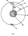
- FIG 1 the motor shaft 10 (attached to the screw of the same number 10 as that of figure 6 of the above-referenced patent, this figure, reference figure 3 , is attached for information purposes to this patent).
- a hub 12 is mounted to rotate freely on this shaft 10.
- This hub carries an arm 14 which, in this case, is pressed against an electromagnet 20, the latter, when supplied, maintains it in this position.
- a spiral spring 18 exerts on the arm 14 a force which tends to make it rotate in the direction A with a torque, for the automobile application, at least equal to 3 Nm at the end of the stroke.
- the direction of movement A corresponds to that of the application of the brake which it actuates, this direction can be reversed, if the specific characteristics of the screws and grooves of said brake justify it.
- a stop 22 will limit the stroke of the arm 14, in particular if this limit cannot be ensured by that of the stroke of the movable assembly of the brake.
- a finger 16, integral with the rotor of the motor will ensure the connection between this device which is the subject of the invention and the brake itself.
- the motor When the brake is powered up, the motor, while ensuring the brake release, goes through the finger 16, to press the arm 14 against the electromagnet 20, in a movement in the opposite direction to A (the torque required will be reversed compared to that of the braking, but of the same order of magnitude).
- the powered electromagnet will hold the arm 14 in position, the spring 18 fully loaded representing the energy storage.
- the finger 16 will then be able to move freely in the space between the two extreme points of its travel represented by the electromagnet 20 and the stop 22 (or the travel limit of the moving assembly of the brake).
- the braking device due to lack of current will have no impact on the performance of the brake, which will therefore be able to move freely in the entire space likely to be used for the various braking operations.
Landscapes
- Engineering & Computer Science (AREA)
- General Engineering & Computer Science (AREA)
- Mechanical Engineering (AREA)
- Transportation (AREA)
- Physics & Mathematics (AREA)
- Electromagnetism (AREA)
- Fluid Mechanics (AREA)
- Chemical & Material Sciences (AREA)
- Combustion & Propulsion (AREA)
- Braking Arrangements (AREA)
- Braking Systems And Boosters (AREA)
- Maintenance And Inspection Apparatuses For Elevators (AREA)
- Valves And Accessory Devices For Braking Systems (AREA)
Description
- La présente invention a pour objectif de créer un système de freinage qui assure le serrage du frein à sa valeur maxi, et son maintien, chaque fois que son alimentation électrique n'est plus assurée, pour des raisons accidentelles ou volontaires.
- Le document
FR 1 264 059 A - On connaît le brevet
européen numéro 1 957 228 du 03.11.2006 relatif à un système de freinage électrique. Ce dispositif utilise un système à gain mécanique variable disposé entre l'arbre moteur et le système de serrage des plaquettes. Si on prend un cahier des charges de frein automobile, pour lequel l'effort sur les plaquettes varie de 0 à 15 kN, avec une déformation élastique de 1 mm, l'énergie nécessaire pour la réalisation de cette opération est de 7,5 Joules. - La course maxi de l'équipage mobile de ce frein est, par construction, de 2,5 rad (inférieure à ½ tour). Si, grâce au système à gain mécanique variable, on ramène au moteur pendant cette opération un couple constant, celui-ci aura, pour délivrer une énergie de 7,5 Joules, une valeur de 3 Nm.
- Ce sont ces valeurs relativement faibles du couple et de la course qui permettent d'envisager cette solution qui consiste à stocker, à chaque mise en route l'énergie qui, en cas de coupure d'alimentation assurera le serrage du frein par manque de courant, et son maintien.
- Les caractéristiques de ces mouvements nous poussent à priori à stocker cette énergie sous une forme mécanique dans des ressorts disposés dans la structure même du frein, cela dit, une solution électrique, notamment par des condensateurs n'est pas à exclure.
- Ce frein à manque de courant va fonctionner en frein d'urgence, il peut aussi être utilisé en frein de parking, assurant l'arrêt du véhicule pendant tout le temps de sa non alimentation. Il peut remplacer le « frein à main ».
- Dans la description qui suit donnée à titre d'exemple, on reconnaît,
figure 1 , l'arbre moteur 10 (solidaire de la vis de même numéro 10 que celui de la figure 6 du brevet ci-dessus référencé, cette figure, référencefigure 3 , est jointe à titre indicatif au présent brevet). Un moyeu 12 est monté libre en rotation sur cet arbre 10. Ce moyeu porte un bras 14 qui, dans ce cas de figure est plaqué contre un électro-aimant 20, celui-ci, lorsqu'il est alimenté le maintient dans cette position. Un ressort spirale 18 exerce sur le bras 14 un effort qui tend à le faire tourner dans le sens A avec un couple, pour l'application automobile, au minimum égal à 3 Nm en fin de course. Le sens de déplacement A correspond à celui du serrage du frein qu'il actionne, ce sens peut être inversé, si les caractéristiques propres des vis et des gorges dudit frein le justifient. Une butée 22, va limiter la course du bras 14, notamment si cette limite ne peut être assurée par celle de la course de l'équipage mobile du frein. Un doigt 16, solidaire du rotor du moteur va assurer la liaison entre ce dispositif objet de l'invention et le frein proprement dit. - A chaque mise sous tension du frein, le moteur, tout en assurant le desserrage du frein, va au travers du doigt 16, plaquer le bras 14 contre l'électro-aimant 20, dans un mouvement en sens inverse de A (le couple nécessaire sera inversé par rapport à celui du freinage, mais du même ordre de grandeur). L'électro-aimant alimenté va maintenir le bras 14 en position, le ressort 18 bandé au maximum représentant le stockage de l'énergie. Le doigt 16 pourra alors se déplacer librement dans l'espace compris entre les deux points extrêmes de sa course que représentent l'électro-aimant 20 et la butée 22 (ou la limite de course de l'équipage mobile du frein). Ainsi, l'ensemble sous tension, le dispositif de freinage par manque de courant n'aura aucune incidence sur les performances du frein qui pourra donc se déplacer librement dans tout l'espace susceptible d'être utilisé pour les différentes opérations de freinage.
- En cas de manque de courant, pour des raisons accidentelles ou volontaires, l'électro-aimant 20 va libérer le bras 14 qui sous la contrainte du ressort 18, va se plaquer contre la butée 22 (ou la limite de la course de l'équipage mobile du frein), dans sa course, il entraînera le doigt 16 (quelle que soit sa position entre 20 et 22) et assurera ainsi, au travers du rotor du moteur, le serrage du frein à sa valeur maxi et son maintien. La
figure 2 représente la disposition des différents composants dans cette nouvelle configuration.
Claims (3)
- Système de serrage de plaquettes dans un frein par manque de courant, le système de serrage comprenant un moteur qui actionne le serrage à travers un arbre moteur (10), un effort sur les plaquettes variant sur une plage de 0 à 15 kN avec une déformation élastique de 1 mm, l'énergie nécessaire pour la réalisation de cette opération étant de 7,5 Joules, un couple constant de 3 Nm sur 2,5 radians étant ramené au moteur pour fournir ledit effort, ces valeurs relativement faibles du couple et de la course permettant une solution comme décrite dans ce qui suit,
le système de serrage tel que, afin de stocker, à chaque mise en route une énergie dans au moins un ressort disposé dans la structure même du frein, l'énergie qui en cas d'une coupure d'alimentation du frein, assurera le serrage du frein par manque de courant, et son maintien, le système de serrage comprend un moyeu (12) monté libre en rotation sur l'arbre moteur (10), le moyeu (12) portant un bras (14), au moins un ressort (18) étant configuré pour exercer sur le bras (14) un effort qui tend à le faire tourner dans un sens A qui correspond au sens du serrage du frein qu'il actionne, un doigt (16) solidaire de l'arbre moteur configuré pour assurer une liaison entre le système de serrage et le frein proprement dit ; le système de serrage étant en outre configuré de telle manière qu'à chaque mise sous tension du frein, ledit moteur, tout en assurant un desserrage du frein, va au travers du doigt (16) solidaire de l'arbre moteur (10), plaquer le bras (14) contre un électro-aimant (20), dans un mouvement en sens inverse du sens A, l'électro-aimant (20) alimenté par l'alimentation électrique du frein maintient le bras (14) en position et le ressort (18) bandé au maximum, stockant l'énergie ; et en cas de manque de courant, pour des raisons accidentelles ou volontaires, l'électro-aimant (20) libère le bras (14) qui, sous la contrainte du ressort (18), va le faire tourner dans le sens A; et, dans sa course, le bras (14) entraine le doigt (16) et assure ainsi, au travers de l'arbre moteur (10), le serrage du frein à une valeur maxi et son maintien. - Le système de serrage selon selon la revendication 1, configuré de sorte que lorsque l'électro-aimant (20) est alimenté, le doigt (16) peut se déplacer librement dans un espace compris entre deux points extrêmes de sa course qui sont respectivement l'électro-aimant (20) et la butée (22), pour que le système de serrage de plaquettes dans le frein par manque de courant n'ait aucune incidence sur les performances du frein qui pourra se déplacer librement dans tout l'espace susceptible d'être utilisé pour les différentes opérations de freinage.
- Le système de serrage selon l'une quelconque des revendications 1 et 2, dans lequel le système est configuré pour être utilisé en frein d'urgence et en frein de parking en remplacement du "frein à main."
Applications Claiming Priority (2)
| Application Number | Priority Date | Filing Date | Title |
|---|---|---|---|
| FR1601376A FR3056271B1 (fr) | 2016-09-21 | 2016-09-21 | Systeme de freinage par manque de courant |
| PCT/FR2017/000167 WO2018055243A1 (fr) | 2016-09-21 | 2017-09-14 | Systeme de freinage par manque de courant |
Publications (2)
| Publication Number | Publication Date |
|---|---|
| EP3515768A1 EP3515768A1 (fr) | 2019-07-31 |
| EP3515768B1 true EP3515768B1 (fr) | 2024-11-06 |
Family
ID=57680306
Family Applications (1)
| Application Number | Title | Priority Date | Filing Date |
|---|---|---|---|
| EP17772454.9A Active EP3515768B1 (fr) | 2016-09-21 | 2017-09-14 | Systeme de freinage par manque de courant |
Country Status (8)
| Country | Link |
|---|---|
| US (1) | US10989261B2 (fr) |
| EP (1) | EP3515768B1 (fr) |
| CN (1) | CN110392649B (fr) |
| CA (1) | CA3037102A1 (fr) |
| ES (1) | ES2996233T3 (fr) |
| FR (1) | FR3056271B1 (fr) |
| RU (1) | RU2744446C2 (fr) |
| WO (1) | WO2018055243A1 (fr) |
Families Citing this family (1)
| Publication number | Priority date | Publication date | Assignee | Title |
|---|---|---|---|---|
| DE102022211584A1 (de) | 2022-11-02 | 2024-05-02 | Robert Bosch Gesellschaft mit beschränkter Haftung | Radbremsmodul, Kraftfahrzeug, Verfahren zum Betreiben des Kraftfahrzeugs |
Family Cites Families (15)
| Publication number | Priority date | Publication date | Assignee | Title |
|---|---|---|---|---|
| FR1264059A (fr) * | 1960-05-07 | 1961-06-19 | J E Desroziers Et Cie | Frein électro-magnétique à manque de courant |
| US4947069A (en) * | 1989-06-08 | 1990-08-07 | Datatape, Inc. | Low power magnetic tape reel motor and brake assembly |
| FR2826622B1 (fr) * | 2001-07-02 | 2003-11-07 | Peugeot Citroen Automobiles Sa | Dispositif de freinage a assistance mecanique d'origine electrique |
| SE0104279D0 (en) * | 2001-12-18 | 2001-12-18 | Haldex Brake Prod Ab | A parking brake arrangement in an electrically operated brake |
| CN2583865Y (zh) * | 2002-12-16 | 2003-10-29 | 苏州宝时得电动工具有限公司 | 断电后自动刹车的电动机 |
| US7604099B2 (en) * | 2004-03-15 | 2009-10-20 | Mitsubishi Electric Corporation | Brake device for elevator |
| CN100339609C (zh) * | 2004-05-31 | 2007-09-26 | 常州合力电器有限公司 | 用于刀片式电动工具的电磁刹车装置 |
| WO2005121006A1 (fr) * | 2004-06-14 | 2005-12-22 | Mitsubishi Denki Kabushiki Kaisha | Dispositif de freinage d’urgence pour ascenseur |
| FR2892963A1 (fr) * | 2005-11-08 | 2007-05-11 | Jean Marc Loriot | Dispositif de rattrapage autonome d'usure. |
| WO2007054633A1 (fr) * | 2005-11-08 | 2007-05-18 | Christian Salesse | Outil de serrage comportant un systeme de compensation autonome |
| KR101098144B1 (ko) * | 2008-12-11 | 2011-12-26 | 현대모비스 주식회사 | 안전 제동 기능을 갖춘 제동 장치 |
| KR101574349B1 (ko) * | 2009-09-08 | 2015-12-11 | 현대모비스 주식회사 | 전자 웨지 브레이크 장치 |
| US8319384B2 (en) * | 2010-12-15 | 2012-11-27 | Honeywell International Inc. | Electromechanical brake actuator motor brake |
| CN202364166U (zh) * | 2011-12-15 | 2012-08-01 | 天津市雄华电子仪表有限公司 | 电动执行器的一种单相伺服电机制动装置 |
| CN203717730U (zh) * | 2014-02-27 | 2014-07-16 | 中联重科股份有限公司 | 常闭式制动器及常闭制动式回转机构 |
-
2016
- 2016-09-21 FR FR1601376A patent/FR3056271B1/fr active Active
-
2017
- 2017-09-14 CA CA3037102A patent/CA3037102A1/fr not_active Abandoned
- 2017-09-14 WO PCT/FR2017/000167 patent/WO2018055243A1/fr not_active Ceased
- 2017-09-14 EP EP17772454.9A patent/EP3515768B1/fr active Active
- 2017-09-14 CN CN201780058089.9A patent/CN110392649B/zh not_active Expired - Fee Related
- 2017-09-14 RU RU2019106948A patent/RU2744446C2/ru active
- 2017-09-14 US US16/335,030 patent/US10989261B2/en active Active
- 2017-09-14 ES ES17772454T patent/ES2996233T3/es active Active
Also Published As
| Publication number | Publication date |
|---|---|
| WO2018055243A1 (fr) | 2018-03-29 |
| FR3056271B1 (fr) | 2022-03-11 |
| CA3037102A1 (fr) | 2018-03-29 |
| US10989261B2 (en) | 2021-04-27 |
| FR3056271A1 (fr) | 2018-03-23 |
| ES2996233T3 (en) | 2025-02-12 |
| RU2744446C2 (ru) | 2021-03-09 |
| US20190249732A1 (en) | 2019-08-15 |
| EP3515768A1 (fr) | 2019-07-31 |
| CN110392649B (zh) | 2021-08-24 |
| CN110392649A (zh) | 2019-10-29 |
| RU2019106948A3 (fr) | 2020-10-05 |
| RU2019106948A (ru) | 2020-09-14 |
Similar Documents
| Publication | Publication Date | Title |
|---|---|---|
| EP2368306B1 (fr) | Moteur electrique pour actionneur rotolineaire. | |
| JP2009209989A (ja) | サーボモータのブレーキ装置 | |
| CA2456663C (fr) | Frein electromecanique a dispositif de parc | |
| EP3515768B1 (fr) | Systeme de freinage par manque de courant | |
| WO2015173037A1 (fr) | Actionneur bi-position et dispositif de pince avec l'actionneur | |
| EP0857644B1 (fr) | Frein à disque perfectionné | |
| EP1801956B1 (fr) | Dispositif de déplacement linéaire d'un corps entre deux positions prédéterminées | |
| FR3016860A1 (fr) | Dispositif de blocage en rotation a structure simplifiee et actionneur comprenant un tel dispositif | |
| JP2004124771A (ja) | 水平軸型風車のブレーキシステム | |
| EP3080475A2 (fr) | Frein à tambour muni d'un organe de retenue d'un segment de freinage | |
| CN111712633B (zh) | 风力发电设备中的制动装置和风力发电设备 | |
| EP4259493B1 (fr) | Actionneur a frein de parking integre | |
| EP2168867A1 (fr) | Actionneur télescopique à tige principale et à tige auxiliaire | |
| EP1610026B1 (fr) | Etrier de frein à disque électromécanique | |
| FR2717303A1 (fr) | Coupe-circuit inertiel pour accumulateurs électriques d'engins auto-moteurs. | |
| EP1791242B1 (fr) | Actionneur linéaire | |
| EP0592286B1 (fr) | Dispositif détecteur d'usure pour garnitures de friction | |
| EP1600655B1 (fr) | Dispositif d'actionnement de frein et frein à disque pour véhicule automobile comportant un tel dispositif | |
| JP3727011B2 (ja) | 作動装置の軸受構造 | |
| WO2024188598A1 (fr) | Infrastructure photovoltaïque comprenant des moyens de mise en sécurité | |
| EP0002631B1 (fr) | Dispositif de freinage automatique pour système rotatif | |
| FR2757966A1 (fr) | Levier de commande d'un dispositif, resistant aux vibrations | |
| FR2915782A1 (fr) | Dispositif de freinage a friction sur un element tournant a actionneur a polymere electroactif | |
| FR2934441A3 (fr) | Moteur rotatif magnetique | |
| EP1852624A1 (fr) | Embrayage électromagnétique à bobine tournante. |
Legal Events
| Date | Code | Title | Description |
|---|---|---|---|
| STAA | Information on the status of an ep patent application or granted ep patent |
Free format text: STATUS: UNKNOWN |
|
| STAA | Information on the status of an ep patent application or granted ep patent |
Free format text: STATUS: THE INTERNATIONAL PUBLICATION HAS BEEN MADE |
|
| PUAI | Public reference made under article 153(3) epc to a published international application that has entered the european phase |
Free format text: ORIGINAL CODE: 0009012 |
|
| STAA | Information on the status of an ep patent application or granted ep patent |
Free format text: STATUS: REQUEST FOR EXAMINATION WAS MADE |
|
| 17P | Request for examination filed |
Effective date: 20190321 |
|
| AK | Designated contracting states |
Kind code of ref document: A1 Designated state(s): AL AT BE BG CH CY CZ DE DK EE ES FI FR GB GR HR HU IE IS IT LI LT LU LV MC MK MT NL NO PL PT RO RS SE SI SK SM TR |
|
| AX | Request for extension of the european patent |
Extension state: BA ME |
|
| DAV | Request for validation of the european patent (deleted) | ||
| DAX | Request for extension of the european patent (deleted) | ||
| STAA | Information on the status of an ep patent application or granted ep patent |
Free format text: STATUS: EXAMINATION IS IN PROGRESS |
|
| 17Q | First examination report despatched |
Effective date: 20200421 |
|
| RAP1 | Party data changed (applicant data changed or rights of an application transferred) |
Owner name: KENDRINOV S.A. |
|
| RIN1 | Information on inventor provided before grant (corrected) |
Inventor name: SALESSE, CHRISTIAN Inventor name: LORIOT, JEAN-MARC |
|
| P01 | Opt-out of the competence of the unified patent court (upc) registered |
Effective date: 20230522 |
|
| GRAP | Despatch of communication of intention to grant a patent |
Free format text: ORIGINAL CODE: EPIDOSNIGR1 |
|
| STAA | Information on the status of an ep patent application or granted ep patent |
Free format text: STATUS: GRANT OF PATENT IS INTENDED |
|
| INTG | Intention to grant announced |
Effective date: 20240507 |
|
| GRAS | Grant fee paid |
Free format text: ORIGINAL CODE: EPIDOSNIGR3 |
|
| GRAA | (expected) grant |
Free format text: ORIGINAL CODE: 0009210 |
|
| STAA | Information on the status of an ep patent application or granted ep patent |
Free format text: STATUS: THE PATENT HAS BEEN GRANTED |
|
| AK | Designated contracting states |
Kind code of ref document: B1 Designated state(s): AL AT BE BG CH CY CZ DE DK EE ES FI FR GB GR HR HU IE IS IT LI LT LU LV MC MK MT NL NO PL PT RO RS SE SI SK SM TR |
|
| REG | Reference to a national code |
Ref country code: GB Ref legal event code: FG4D Free format text: NOT ENGLISH |
|
| REG | Reference to a national code |
Ref country code: CH Ref legal event code: EP |
|
| REG | Reference to a national code |
Ref country code: DE Ref legal event code: R096 Ref document number: 602017085940 Country of ref document: DE |
|
| REG | Reference to a national code |
Ref country code: IE Ref legal event code: FG4D Free format text: LANGUAGE OF EP DOCUMENT: FRENCH |
|
| REG | Reference to a national code |
Ref country code: ES Ref legal event code: FG2A Ref document number: 2996233 Country of ref document: ES Kind code of ref document: T3 Effective date: 20250212 |
|
| REG | Reference to a national code |
Ref country code: LT Ref legal event code: MG9D |
|
| REG | Reference to a national code |
Ref country code: NL Ref legal event code: MP Effective date: 20241106 |
|
| PG25 | Lapsed in a contracting state [announced via postgrant information from national office to epo] |
Ref country code: IS Free format text: LAPSE BECAUSE OF FAILURE TO SUBMIT A TRANSLATION OF THE DESCRIPTION OR TO PAY THE FEE WITHIN THE PRESCRIBED TIME-LIMIT Effective date: 20250306 Ref country code: PT Free format text: LAPSE BECAUSE OF FAILURE TO SUBMIT A TRANSLATION OF THE DESCRIPTION OR TO PAY THE FEE WITHIN THE PRESCRIBED TIME-LIMIT Effective date: 20250306 Ref country code: HR Free format text: LAPSE BECAUSE OF FAILURE TO SUBMIT A TRANSLATION OF THE DESCRIPTION OR TO PAY THE FEE WITHIN THE PRESCRIBED TIME-LIMIT Effective date: 20241106 |
|
| PG25 | Lapsed in a contracting state [announced via postgrant information from national office to epo] |
Ref country code: FI Free format text: LAPSE BECAUSE OF FAILURE TO SUBMIT A TRANSLATION OF THE DESCRIPTION OR TO PAY THE FEE WITHIN THE PRESCRIBED TIME-LIMIT Effective date: 20241106 Ref country code: NL Free format text: LAPSE BECAUSE OF FAILURE TO SUBMIT A TRANSLATION OF THE DESCRIPTION OR TO PAY THE FEE WITHIN THE PRESCRIBED TIME-LIMIT Effective date: 20241106 |
|
| REG | Reference to a national code |
Ref country code: AT Ref legal event code: MK05 Ref document number: 1739058 Country of ref document: AT Kind code of ref document: T Effective date: 20241106 |
|
| PG25 | Lapsed in a contracting state [announced via postgrant information from national office to epo] |
Ref country code: BG Free format text: LAPSE BECAUSE OF FAILURE TO SUBMIT A TRANSLATION OF THE DESCRIPTION OR TO PAY THE FEE WITHIN THE PRESCRIBED TIME-LIMIT Effective date: 20241106 |
|
| PG25 | Lapsed in a contracting state [announced via postgrant information from national office to epo] |
Ref country code: NO Free format text: LAPSE BECAUSE OF FAILURE TO SUBMIT A TRANSLATION OF THE DESCRIPTION OR TO PAY THE FEE WITHIN THE PRESCRIBED TIME-LIMIT Effective date: 20250206 |
|
| PG25 | Lapsed in a contracting state [announced via postgrant information from national office to epo] |
Ref country code: LV Free format text: LAPSE BECAUSE OF FAILURE TO SUBMIT A TRANSLATION OF THE DESCRIPTION OR TO PAY THE FEE WITHIN THE PRESCRIBED TIME-LIMIT Effective date: 20241106 Ref country code: GR Free format text: LAPSE BECAUSE OF FAILURE TO SUBMIT A TRANSLATION OF THE DESCRIPTION OR TO PAY THE FEE WITHIN THE PRESCRIBED TIME-LIMIT Effective date: 20250207 Ref country code: AT Free format text: LAPSE BECAUSE OF FAILURE TO SUBMIT A TRANSLATION OF THE DESCRIPTION OR TO PAY THE FEE WITHIN THE PRESCRIBED TIME-LIMIT Effective date: 20241106 |
|
| PG25 | Lapsed in a contracting state [announced via postgrant information from national office to epo] |
Ref country code: PL Free format text: LAPSE BECAUSE OF FAILURE TO SUBMIT A TRANSLATION OF THE DESCRIPTION OR TO PAY THE FEE WITHIN THE PRESCRIBED TIME-LIMIT Effective date: 20241106 |
|
| PG25 | Lapsed in a contracting state [announced via postgrant information from national office to epo] |
Ref country code: RS Free format text: LAPSE BECAUSE OF FAILURE TO SUBMIT A TRANSLATION OF THE DESCRIPTION OR TO PAY THE FEE WITHIN THE PRESCRIBED TIME-LIMIT Effective date: 20250206 |
|
| PG25 | Lapsed in a contracting state [announced via postgrant information from national office to epo] |
Ref country code: SM Free format text: LAPSE BECAUSE OF FAILURE TO SUBMIT A TRANSLATION OF THE DESCRIPTION OR TO PAY THE FEE WITHIN THE PRESCRIBED TIME-LIMIT Effective date: 20241106 |
|
| PG25 | Lapsed in a contracting state [announced via postgrant information from national office to epo] |
Ref country code: DK Free format text: LAPSE BECAUSE OF FAILURE TO SUBMIT A TRANSLATION OF THE DESCRIPTION OR TO PAY THE FEE WITHIN THE PRESCRIBED TIME-LIMIT Effective date: 20241106 |
|
| PG25 | Lapsed in a contracting state [announced via postgrant information from national office to epo] |
Ref country code: EE Free format text: LAPSE BECAUSE OF FAILURE TO SUBMIT A TRANSLATION OF THE DESCRIPTION OR TO PAY THE FEE WITHIN THE PRESCRIBED TIME-LIMIT Effective date: 20241106 |
|
| PG25 | Lapsed in a contracting state [announced via postgrant information from national office to epo] |
Ref country code: RO Free format text: LAPSE BECAUSE OF FAILURE TO SUBMIT A TRANSLATION OF THE DESCRIPTION OR TO PAY THE FEE WITHIN THE PRESCRIBED TIME-LIMIT Effective date: 20241106 |
|
| PG25 | Lapsed in a contracting state [announced via postgrant information from national office to epo] |
Ref country code: SK Free format text: LAPSE BECAUSE OF FAILURE TO SUBMIT A TRANSLATION OF THE DESCRIPTION OR TO PAY THE FEE WITHIN THE PRESCRIBED TIME-LIMIT Effective date: 20241106 |
|
| PG25 | Lapsed in a contracting state [announced via postgrant information from national office to epo] |
Ref country code: CZ Free format text: LAPSE BECAUSE OF FAILURE TO SUBMIT A TRANSLATION OF THE DESCRIPTION OR TO PAY THE FEE WITHIN THE PRESCRIBED TIME-LIMIT Effective date: 20241106 |
|
| PG25 | Lapsed in a contracting state [announced via postgrant information from national office to epo] |
Ref country code: IT Free format text: LAPSE BECAUSE OF FAILURE TO SUBMIT A TRANSLATION OF THE DESCRIPTION OR TO PAY THE FEE WITHIN THE PRESCRIBED TIME-LIMIT Effective date: 20241106 |
|
| REG | Reference to a national code |
Ref country code: DE Ref legal event code: R097 Ref document number: 602017085940 Country of ref document: DE |
|
| PG25 | Lapsed in a contracting state [announced via postgrant information from national office to epo] |
Ref country code: SE Free format text: LAPSE BECAUSE OF FAILURE TO SUBMIT A TRANSLATION OF THE DESCRIPTION OR TO PAY THE FEE WITHIN THE PRESCRIBED TIME-LIMIT Effective date: 20241106 |
|
| PLBE | No opposition filed within time limit |
Free format text: ORIGINAL CODE: 0009261 |
|
| STAA | Information on the status of an ep patent application or granted ep patent |
Free format text: STATUS: NO OPPOSITION FILED WITHIN TIME LIMIT |
|
| REG | Reference to a national code |
Ref country code: CH Ref legal event code: U11 Free format text: ST27 STATUS EVENT CODE: U-0-0-U10-U11 (AS PROVIDED BY THE NATIONAL OFFICE) Effective date: 20251001 |
|
| PGFP | Annual fee paid to national office [announced via postgrant information from national office to epo] |
Ref country code: DE Payment date: 20250919 Year of fee payment: 9 |
|
| 26N | No opposition filed |
Effective date: 20250807 |
|
| PGFP | Annual fee paid to national office [announced via postgrant information from national office to epo] |
Ref country code: FR Payment date: 20250922 Year of fee payment: 9 |
|
| PGFP | Annual fee paid to national office [announced via postgrant information from national office to epo] |
Ref country code: CH Payment date: 20251001 Year of fee payment: 9 |
|
| PGFP | Annual fee paid to national office [announced via postgrant information from national office to epo] |
Ref country code: ES Payment date: 20251030 Year of fee payment: 9 |