EP3516143B1 - Système de ferrure - Google Patents
Système de ferrure Download PDFInfo
- Publication number
- EP3516143B1 EP3516143B1 EP17758526.2A EP17758526A EP3516143B1 EP 3516143 B1 EP3516143 B1 EP 3516143B1 EP 17758526 A EP17758526 A EP 17758526A EP 3516143 B1 EP3516143 B1 EP 3516143B1
- Authority
- EP
- European Patent Office
- Prior art keywords
- scissor
- arm
- scissor arm
- scissor stay
- side end
- Prior art date
- Legal status (The legal status is an assumption and is not a legal conclusion. Google has not performed a legal analysis and makes no representation as to the accuracy of the status listed.)
- Active
Links
Images


Classifications
-
- E—FIXED CONSTRUCTIONS
- E05—LOCKS; KEYS; WINDOW OR DOOR FITTINGS; SAFES
- E05D—HINGES OR SUSPENSION DEVICES FOR DOORS, WINDOWS OR WINGS
- E05D15/00—Suspension arrangements for wings
- E05D15/48—Suspension arrangements for wings allowing alternative movements
- E05D15/52—Suspension arrangements for wings allowing alternative movements for opening about a vertical as well as a horizontal axis
- E05D15/5205—Suspension arrangements for wings allowing alternative movements for opening about a vertical as well as a horizontal axis with horizontally-extending checks
-
- E—FIXED CONSTRUCTIONS
- E05—LOCKS; KEYS; WINDOW OR DOOR FITTINGS; SAFES
- E05Y—INDEXING SCHEME ASSOCIATED WITH SUBCLASSES E05D AND E05F, RELATING TO CONSTRUCTION ELEMENTS, ELECTRIC CONTROL, POWER SUPPLY, POWER SIGNAL OR TRANSMISSION, USER INTERFACES, MOUNTING OR COUPLING, DETAILS, ACCESSORIES, AUXILIARY OPERATIONS NOT OTHERWISE PROVIDED FOR, APPLICATION THEREOF
- E05Y2800/00—Details, accessories and auxiliary operations not otherwise provided for
- E05Y2800/37—Length, width or depth adjustment
-
- E—FIXED CONSTRUCTIONS
- E05—LOCKS; KEYS; WINDOW OR DOOR FITTINGS; SAFES
- E05Y—INDEXING SCHEME ASSOCIATED WITH SUBCLASSES E05D AND E05F, RELATING TO CONSTRUCTION ELEMENTS, ELECTRIC CONTROL, POWER SUPPLY, POWER SIGNAL OR TRANSMISSION, USER INTERFACES, MOUNTING OR COUPLING, DETAILS, ACCESSORIES, AUXILIARY OPERATIONS NOT OTHERWISE PROVIDED FOR, APPLICATION THEREOF
- E05Y2900/00—Application of doors, windows, wings or fittings thereof
- E05Y2900/10—Application of doors, windows, wings or fittings thereof for buildings or parts thereof
- E05Y2900/13—Type of wing
- E05Y2900/148—Windows
Definitions
- the present invention relates to a fitting arrangement for a window, a door or the like for mounting a sash on a frame, which can be rotated about an axis of rotation and can be tilted about a tilt axis, and a window, a door or the like with such a fitting arrangement.
- Such fitting arrangements make it possible to open the sash in at least two different ways, namely to tilt-open or to open-turn.
- the axis of rotation and the tilt axis are oriented perpendicular to one another, the axis of rotation generally being oriented vertically and the tilting axis being oriented horizontally.
- the two types of opening can also differ with regard to the possible opening width.
- rotary opening is possible up to an angle of at least 90 °, preferably significantly beyond, in order to fully open the window or door, whereas tilt opening to a significantly smaller opening angle, for example at most about 20 °, so that, for example, to ventilate the wing, only a gap is tilted open.
- the fitting arrangement can typically comprise a faceplate, a scissor arm and a scissor link, the faceplate being designed to be attached to a side of the sash remote from the tilt axis; wherein the scissor arm is designed to be mounted on the frame with one end on the frame side, in particular via a scissor bearing, so as to be rotatable about the axis of rotation, and with one end on the wing side is articulated on the faceplate; and wherein the scissor link is articulated with an arm-side end to a fork section of the scissor arm and is articulated with a wing-side end to the faceplate.
- the pivotable and tilt-openable mounting of the respective sash on the respective frame thus takes place at least in part via the mentioned elements of the fitting arrangement.
- the faceplate to be fastened to the wing serves, among other things, to provide reliable coupling options for the scissor arm and the scissor link on the wing.
- the scissor arm is essentially used to connect the sash to the frame. For this purpose, it is hinged to the faceplate with its wing-side end and can be supported on the frame with its frame-side end. In order to enable the sash to be opened to rotate, this mounting on the frame side is preferably such that the scissor arm is rotatable about the axis of rotation.
- the scissor arm can be connected or connectable to a scissor bearing attached or to be attached to the frame.
- the scissor arm contributes significantly to the mounting of the sash on the frame.
- the scissor arm supports the wing in its rotatably open state against the force of gravity acting on the wing.
- the scissor arm is usually arranged on an upper side of the wing, which in this respect is carried by the scissor arm.
- the scissor link creates an additional connection between the scissor arm and the faceplate, with which it is connected in an articulated manner.
- it In the closed and rotatably open state of the sash, it is usually aligned parallel to the scissor arm and the faceplate.
- the scissor arm In the wing is tilted open and the scissor arm swings out in relation to the faceplate, the scissor arm is consequently swiveled out in a similar manner, so that it bridges the opening angle between the scissor arm and the faceplate in particular.
- the cross connection formed in this way by the scissor link between the scissor arm and the faceplate can advantageously contribute to the stability of the mounting of the sash on the frame.
- the faceplate, the scissor arm and the scissor link can each have at least essentially a strip shape, that is to say an elongated, flat shape.
- the named frame-side, wing-side or arm-side ends can in particular be formed by respective end regions of the longitudinal extension of the respective strip shape.
- the sash is closed or tilted open (with a tilt axis typically provided on a lower side of the sash), the sash can be supported on the frame, so that a correct alignment of the sash can already be guaranteed.
- the fitting arrangement in particular the mentioned length of the scissor arm, which effectively contributes to the bearing, is incorrectly set, this consequently has an effect in particular on the alignment of the sash in the rotationally open state.
- the wing is then, for example, lowered or raised in relation to a correct alignment. If such a misaligned sash is then closed in rotation, it can happen that the sash does not pivot flush into the frame, but runs against the frame on one side. It is true that the wing can possibly be brought into the closed position by this opening, in which it is then correctly aligned with the frame.
- the correction is not permanent, but rather the sash re-aligns itself incorrectly as a result of the wrong length of the scissor arm the next time the pivot is opened and thus runs against the frame again when the pivot is closed.
- repeated opening can lead to increased wear, both on the sash and frame and, due to the resulting irregular loading, on the fitting arrangement itself.
- the run-up can be audible or otherwise perceptible as faulty and disruptive.
- the misalignment of the sash does not have to be based on a fitting arrangement that was set incorrectly from the start, for example during assembly, but can only arise over time due to the dead weight of the sash. This can in particular lead to the fact that the wing "settles" as a result of its own slight deformations and / or as a result of slight deformations in the mounting, ie lowers a little, so that an adjustment of the fitting arrangement is necessary to compensate for the misalignment.
- the fitting arrangement is set in such a way that the sash is held in the correct orientation when it is pivoted from the closed position in which it is received flush in the frame and is advantageously already held and supported in the correct orientation by the frame itself, even if the frame is no longer supported by opening the door.
- the fitting arrangement In order to compensate for this lack of support in the rotatably open state, the fitting arrangement must leave little play in the sash, particularly in the direction of lowering, so that the scissor arm between the sash and the frame preferably produces a rather tight connection.
- the scissor arm is designed in at least two parts and comprises a support member on which the frame-side end of the scissor arm is formed, and a separate pivot member on which the wing-side end of the scissor arm is formed, the support member and the pivot member relative to one another are displaceable, in particular along a longitudinal axis of the scissor arm.
- the support member and the pivot member can be displaced relative to one another in such a way that the distance between the fork section and the wing-side end of the scissor arm is variable.
- the support member is displaced relative to the pivot member in the area between the fork section on which the scissor link is hinged and the wing-side end of the scissor arm on which the scissor arm is hinged to the faceplate.
- the pivoting member can be made comparatively short, while the support member extends over the major part of the length of the scissor arm.
- the area between the fork section and the frame-side end of the scissor arm preferably comprises more than half, in particular more than two thirds, particularly preferably more than three quarters, of the length of the scissor arm.
- the area between the fork section and the frame-side end of the scissor arm can be essentially rigid, i.e. in particular with a constant length, which advantageously results in reliable storage of the wing.
- the support member and the pivot member of the scissor arm can be coupled directly to one another or else via one or more further elements so that they can be displaced relative to one another. Since the frame-side end of the scissor arm is formed on the support member and the wing-side end is on the pivot member, an offset of the support member relative to the pivot member leads to a corresponding change in the distance between the frame-side and the wing-side end of the scissor arm and thus to a change in length of the Scissor arm.
- the displaceability of the support member relative to the pivot member can be limited, so that the length of the scissor arm can change, in particular freely, within a defined length range.
- This length variability which is free within the defined length range, can be used in particular for the tilt opening of the sash, in which the scissor arm connecting the sash to the frame swings out and bridges the opening gap at an angle. Because the scissor arm can be lengthened relative to the pivot member by moving the support member, the point at which the scissor arm is hinged with its wing-side end to the faceplate does not need to be designed to be variable in order to enable the tilt opening.
- the maximum width of the tilt opening can be determined by the amount of free extensibility of the scissor arm, which is predetermined by the amount of displaceability of the support member relative to the pivot member.
- the ability to freely change the length of the scissor arm thus enables an advantageous embodiment in which it is provided that the wing-side end of the scissor arm is articulated to a fixed pivot point of the faceplate.
- This has the advantage that there is no need to provide a structurally more complex variable articulation point for the scissor arm on the faceplate.
- a fixed pivot point can basically be made more stable.
- the scissor link can also be articulated with its wing-side end to a fixed pivot point of the faceplate. Because also with the scissor link there is basically the corresponding problem that a changing distance between the scissor arm and the faceplate has to be bridged when the scissor arm and the scissor link are opened due to a tilt opening of the sash. For improved stability, this problem is then nevertheless not solved by a variable articulation point of the scissor link on the faceplate, but rather a fixed pivot point is provided.
- the arm-side end of the scissors link is articulated to a fork point of the scissor arm that is variable within the fork section, in particular along the longitudinal axis of the scissor arm.
- a fork point that is variable within the fork section enables the scissor arm to always connect the fork section of the stay arm to the faceplate regardless of the width of the tilt opening, without that the scissor link must be variable in length for this.
- the scissor arm and the scissor link cooperate in such a way that, depending on the respective relative angular alignment of the scissor arm and the scissor link, the variability of the fork point within the fork section is limited in the direction of the wing-side end of the scissor arm. In other words, the position of the fork point cannot always be freely taken within the entire fork section, it is influenced by how the scissor link is oriented relative to the scissor arm.
- the respective position of the fork point within the fork section is preferably clearly predetermined by the respective angular alignment of the scissor link relative to the scissor arm.
- the variability of the fork point is only restricted to a degree that is dependent on the respective angular orientation, and specifically preferably at least on one side in the direction of the wing-side end of the scissor arm.
- the fork point within the fork section is not always variable over its entire extent, but at least in the direction of the wing-side end of the scissor arm only up to a respective limit position, which depends on the respective angular orientation of the scissor arm relative to the scissor arm.
- the variability of the fork point within the fork section can be more limited in the direction of the wing-side end of the scissor arm, the less the alignment of the scissor link and the alignment of the scissor arm differ from one another.
- the fork point is thus kept within the fork section particularly far from the wing-side end of the scissor arm, whereas the fork point is when the tilt opening is the scissor arm and the scissor link can shear open to move within the fork section on the wing-side end of the scissor arm.
- the fork point at each other parallel alignment of the scissor arm and the scissor link is further away from the wing-side end of the scissor arm than with an angled alignment of the scissor arm and the scissor link.
- the fork point is automatically offset within the fork section in the direction away from the wing-side end of the scissor arm when the sash is tilted.
- This displacement of the fork point within the fork section can, in particular if the scissor link is hinged with its wing-side end to a fixed pivot point of the faceplate, to a reverse displacement of the support member of the scissor arm in the direction of its wing-side end, which then corresponds to a shortening of the scissor arm.
- the length of the scissor arm is always shortened by a certain amount, which is predetermined by the angular dependency of the position of the fork point within the fork section and for example between 1 and 10 mm, in particular between 2 and 8 mm, preferably about 4 mm can be.
- the advantage of such an automatic shortening of the length of the scissor arm when tilt closing is that the shortening tightens the scissor arm, so to speak, and thus prepares it for a pivot opening of the sash, in which the scissor arm bears a substantial part of the weight of the sash.
- the tightening shortening of the scissor arm can serve at least essentially to compensate for possible play in the fitting arrangement.
- the length of the scissor arm can automatically lengthen again in a similar manner, in particular by the same amount, so that the scissor arm is so to speak relaxed and thus relieved.
- the scissor arm has a guide slot on which a guide section of the scissor link is guided as a function of the relative angular alignment of the scissor arm and the scissor link.
- the embodiment can also be designed exactly the other way round, so that the scissor link has a guide slot on which a guide section of the scissor arm is guided depending on the relative angular alignment of the scissor arm and the scissor link. It is precisely through the interaction of the respective guide link with the respective guide section that the above-described dependency of the position of the fork point within the fork section on the relative angular alignment of the scissor arm and the scissor link can be realized.
- the pivotability of the scissor link is limited to a maximum pivoted-out orientation by a stop formed in particular on the scissor arm or on the faceplate.
- the scissor link strikes the stop when it assumes the maximum pivoted orientation relative to the scissor arm, so that it cannot be pivoted beyond that.
- the scissor arm further comprises an intermediate member which is coupled to the support member and to the pivot member and which can be displaced relative to the pivot member, in particular along the longitudinal axis of the scissor arm, the fork section on the intermediate member is trained.
- the scissor arm is therefore not only designed in two parts, but at least in three parts and comprises the pivot member, the intermediate member and the support member.
- the intermediate member coupled to the pivot member and the support member can in particular serve to connect the pivot member to the support member so that the support member is only indirectly connected to the pivot member.
- the scissors link is also coupled to the intermediate link.
- the support member can in particular extend over a predominant part of the length of the scissor arm and thus serve to bridge the distance between the fork section and the wing-side ends of the fitting arrangement on the one hand and the frame-side end mounted on the frame on the other.
- the pivot member can essentially serve to articulate the scissor arm to the faceplate and also provide guide means for moving the intermediate member or the support member along the longitudinal axis of the scissor arm.
- the scissors arm creates a cross connection between the fork section and the wing for additional stabilization of the arrangement.
- the named intermediate member can be viewed as the central link between these movable elements of the fitting arrangement.
- the intermediate member and the support member can be firmly connected to each other so that they can be moved together relative to the pivot member, so that the length of the scissor arm for the tilt opening and the thereby increasing distance between the sash and the frame can automatically increase Tilt-closing can decrease again accordingly.
- the support member is displaceable relative to the intermediate member, in particular along the named longitudinal axis of the scissor arm, locking means being provided between the support member and the intermediate member in order to determine a relative position of the support member and the intermediate member.
- locking means being provided between the support member and the intermediate member in order to determine a relative position of the support member and the intermediate member.
- the support member and the intermediate member in addition to the displaceability of the support member or the intermediate member relative to the pivot member, there is also provision for the support member and the intermediate member to be displaceable relative to one another.
- this displaceability is not fundamentally free, but the support member and the intermediate member can be fixed in a respective position relative to one another by locking means.
- the locking means In order to move the support member relative to the intermediate member, the locking means must therefore first be released, whereby such release can basically be done manually, but also automatically, e.g. depending on a respective position, alignment or direction of displacement.
- the displaceability between the support member and the intermediate member can thus be used for a basic length adjustment or adjustment of the scissor arm, whereas the displaceability of the support member or the intermediate member relative to the pivot member only serves to reduce the due to the pivoting in the tilt-open state compared to the closed or to enable the swivel arm required increase in length in the pivoted open state. It is particularly advantageous to provide the basic length adjustability in the area between the fork section and the wing-side end of the scissor arm, since the locking means can then be actuated depending on the orientation, for example by interacting with the pivoting member or the scissor link, as will be explained below.
- the locking means are pretensioned in a locking state, that is to say determining the relative position of the support member and the intermediate member.
- the support member and the intermediate member form a unit of defined length as long as the locking means are not released against the bias.
- the scissor arm can perform the usual function of supporting the wing or limiting its tilt opening.
- An offset of the support member relative to the intermediate member is namely not necessary for this usual function and could even be a hindrance.
- the displacement of the support member relative to the intermediate member is at least essentially only necessary if the length of the scissor arm is incorrectly set and therefore has to be corrected. It is therefore advantageous if the locking means are normally kept in the locking state by the bias.
- the blocking means block a displacement of the support member relative to the intermediate member in one direction, in particular in the direction of increasing the distance between the fork section and the frame-side end of the scissor arm, and in a direction opposite to this.
- the locking means determine the relative position of the support member and the intermediate member. If, however, the support member and the intermediate member are acted upon for displacement in a specific direction relative to one another, this displacement can be permitted by the locking means differently than in the case of an opposite action. In other words, the locking means are released automatically in a defined displacement direction.
- the locking means can be designed as latching means in such an embodiment.
- the locking means reliably counteract an increase in the distance between the fork section and the frame-side end of the scissor arm, that is, an extension of the scissor arm. Because in this direction the scissor arm is in particular loaded when the sash is open. But then the scissor arm should reliably carry the wing, which is why an extension of the scissor arm must be prevented.
- the support member and the intermediate member are correspondingly offset relative to one another as a result of the impact and are fixed again in the new relative position by the locking means. In this way, the length of the scissor arm can be automatically adjusted to compensate for the misalignment of the wing.
- the locking means are designed to interact in particular with the pivot member in such a way that, depending on the relative position of the pivot member and the intermediate member, in particular when a maximum distance is reached between the fork section and the wing-side end of the scissor arm, they merge into one Displacement of the support member can be adjusted relative to the intermediate member releasing state.
- the locking means are automatically released depending on the relative position of the pivot member and the intermediate member.
- the locking means are automatically released when the fork section reaches a maximum distance from the wing-side end of the scissor arm.
- the locking means While the locking means must hold the support member and the intermediate member reliably in their respective relative position when the sash is open to rotate, so that the sash is reliably supported, they can be safely released when the sash is tilted, since the sash is primarily not supported by the scissor arm, but by the frame becomes.
- the tilt-open state is therefore also suitable for enabling automatic length adjustment of the scissor arm in the direction of an extension.
- a scissor arm that is set too short can be present immediately after installation, for example.
- the closed state of the sash in which the sash is held correctly aligned by the frame, the insufficient length then leads to an impact on the scissor arm in the direction of an extension, which, however, due to the locking means that determine the relative position of the support member and the intermediate member, can be locked.
- the sash After assembly, however, the sash only needs to be tilted open once in order to set the length correctly. Because in the tilt-open state, the locking means can automatically release in this embodiment, so that the sash resting on the frame can align itself correctly and the length of the scissor arm can thus automatically extend to the dimension corresponding to the correct alignment. With tilt locking, the release of the locking means is then canceled again, so that the correct length is then maintained.
- the length of the scissor arm can automatically be suitably lengthened by tilting opening and closing and automatically suitably shortened by turning opening and closing.
- the manual length adjustment of the scissor arm which is usually required during assembly, can also be omitted entirely. Since the locking means always permit a shortening of a scissor arm that is too long and, in the tilt-open state, an extension of a scissor arm that is too long is made possible, the wing only needs to be tilted open and closed once to adjust the length of the scissor arm after assembly. A subsequent lowering of the sash over time (so-called "setting”) is also automatically compensated for each time the sash is turned, that is, essentially through normal use.
- the locking means are formed as interlocking, in particular asymmetrical, toothings formed on the one hand on the support member and on the other hand on the intermediate member.
- the locking means can be designed in a structurally simple manner, in particular also in the manner of latching means.
- the toothings are then brought into engagement with one another, in particular by the pretensioning mentioned.
- the tooth flanks can be designed so asymmetrically in relation to the possible displacement directions of the support member and the intermediate member relative to each other that the teeth automatically at least temporarily disengage when moved in one direction and thus allow displacement, in the other direction remain engaged and thus block the move.
- the object of the invention is also achieved by a window, a door or the like with a fitting arrangement according to one of the embodiments described above.
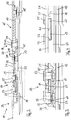
- a fitting arrangement 11 comprises a faceplate 13, a scissor arm 15 (cf. Fig. 2 and 5 ) and a scissor link 17.
- the fitting arrangement 11 is not shown in full. In particular, only a central area of the faceplate 13 is shown, which is essentially delimited by the two fixed pivot points 19, 19 ′ at which the scissor arm 15 or the scissor link 17 is hinged to the faceplate 13 is.
- the scissor arm 15 comprises a support member 21, a pivot member 23 and an intermediate member 25, of which in FIG Fig. 1 only the pivot member 23 and the intermediate member 25 are shown.
- the support member 21 is in the other figures, in particular in Fig. 5 complete, shown.
- the faceplate 13 is designed to be attached to the side of a sash, not shown, of a window, a door or the like, which is opposite a tilt axis for tilt opening. After the fastening, the faceplate 13 is then arranged in a fixed position relative to the sash, but when the sash is tilted open, it can move away together with the sash parallel to the frame, also not shown (in the Fig. 1 and 5 to 8 in the display level down).
- the scissor arm 15 is used to connect the faceplate 13 to a frame-side scissor bearing 26 (cf. Fig. 5 ), via which the scissor arm 15 is rotatably mounted on the frame about an axis of rotation D for opening the sash in rotation.
- the scissor arm 15 can support the wing so that part of the weight of the wing is carried off by the scissor arm 15 when the wing is rotatably open.
- the scissor arm 15 is provided with an end 27 on the frame side (cf. Fig. 5 ), which is formed on the support member 21, attached to the scissor bearing 26 and hinged with a wing-side end 29, which is formed on the pivot member 23, to the fixed pivot point 19 on the faceplate 13.
- the scissor arm 15 In the closed or rotatably open state of the wing, the scissor arm 15, as in particular in FIG Fig. 1a ) and 5a ) shown, aligned parallel to the faceplate 13.
- the faceplate 13 When the sash is tilted open, the faceplate 13 is offset in parallel, so that the stay arm 15 connecting the fixed pivot point 19 on the faceplate 13 to the stay bearing 26, as in particular in FIG Figure 1b ) and 5b ) swings out and the distance to be bridged by the scissor arm 15 is thus increased.
- the support member 21 can be displaced relative to the pivot member 23 along the longitudinal axis L of the scissor arm 15 so that the length of the scissor arm 15 can be freely changed at least within a certain range. In this way, when the sash is tilted open, the length of the scissor arm 15 is automatically lengthened to the extent required for this and is correspondingly shortened again when the sash is tilted closed.
- Support member 21, not shown, is coupled to the intermediate member 25, which in turn can be displaced relative to the pivot member 23 along the longitudinal axis L.
- the named change in length to enable tilting opening and closing thus results at least essentially from the displaceability of the intermediate member 25 relative to the pivotable pivot member 23 which is articulated at the fixed pivot point 19.
- the pivot member 23 and the intermediate member 25 are connected via a pin 31 formed on the frame side on the pivot member 23, which engages in an elongated hole 33 formed on the intermediate member 25 and extending along the longitudinal axis L and within the elongated hole 33 along the longitudinal axis L of the scissor arm 15 is movable.
- the intermediate member 25 is at least partially flanked on both narrow sides of its strip shape by wall sections 34 of the pivot member 23, which in particular ensure that the intermediate member 25 and the intermediate member 25 are always aligned parallel to one another.
- the interaction of the pin 31 with the elongated hole 33 defines the relative displaceability of the pivot member 23 and the intermediate member 25.
- the degree of displaceability is limited by the length of the elongated hole 33, which is selected so that the change in length required for the tilt opening or closing of the scissor arm 15 is made possible, as well as the comparison of the Fig. 1a) and 1b ) shows, in which the pin 31 is arranged at a respective other end of the elongated hole 33.
- the maximum width of the tilt opening can be determined (among other things) by the length of the elongated hole 33.
- the scissors link 17 is hinged with a wing-side end 35 to the further fixed pivot point 19 ′ on the faceplate 13 and with the opposite end 37 on the arm side is hinged to a fork section 39 of the scissor arm 15.
- the fork section 39 is defined by a further elongated hole 41 which is formed on the frame side in the intermediate member 25 (cf. Fig. 2 ) and in which a pin 43 provided on the arm-side end 37 of the scissor link 17 engages.
- the respective position of the pin 43 within the elongated hole 41 defines a respective fork point 45, which is thus basically variable within the fork section 39 defined by the elongated hole 41.
- the pin 43 cannot move freely within the elongated hole 41. Rather, its position and thus the position of the fork point 45 within the fork section 39 depends on the respective angular alignment of the scissors arm 17 relative to the intermediate member 25. Because on the wing side adjacent to the elongated hole 41, a guide slot 47 in the form of a step is formed on the intermediate member 25, on which a guide section 49 formed in the area of the arm-side end 37 of the scissors link 17 rests. When the scissors arm 17 is pivoted relative to the intermediate member 25, the guide section 49 slides along the guide slot 47. The course of the guide section 49 has a distance to the pin 43 that decreases continuously from the arm-side end 37 to the side. As a result, when the scissors link 17 is aligned parallel to the intermediate link 25, the pin 43 is held at a greater distance from the guide link 47 than when the scissors link 17 is pivoted out.
- a stop 51 is also formed on the intermediate member 25, by means of which the scissor link 17 is limited to a maximum angular alignment of approximately 45 ° to 50 ° relative to the intermediate member 25 or to the scissor arm 15.
- the limitation takes place in that the scissor link 17, as in Figure 1b ) shown, strikes the stop 51 when the maximum angular alignment is reached and therefore cannot be deflected any further.
- the stop 51 thus contributes to the definition of the maximum width of the tilt opening.
- the support member 21 is essentially connected to the intermediate member 25 via two pins 53, 53 ', which are provided on the intermediate member 25 on the wing side adjacent to one another along the longitudinal axis L and in each case one of two arranged on the wing side of the support member 21 and Engage parallel to the longitudinal axis L aligned elongated holes 55, 55 'of the same length.
- the pin 43 of the scissors link 17 extends through a further one formed in the support member 21 Elongated hole 57.
- the length of the elongated holes 55, 55 ' fines a basic displaceability of the support member 21 relative to the intermediate member 25.
- the further elongated hole 57 is longer in order to enable the additional variability of the position of the fork point 45 within the fork section 39.
- the support member 21 is not freely displaceable relative to the intermediate member 25. Instead, locking means 59 are provided in the area between the pins 53, 53 ', which fix the support member 21 in a respective relative position relative to the intermediate member 25.
- the locking means 59 are designed in the form of a tooth system 61 provided on the support member 21 and a counter tooth system 63 provided on the intermediate member 25.
- the counter-toothing 63 is formed on a plate 67 that is separate from the rest of the intermediate member 25 and is pretensioned in the direction of engagement with the toothing 61 by means of a spring device 65 designed as a plate spring (cf. Fig. 3 ).
- the support member 21 and the intermediate member 25 form a unit of defined length.
- a change in length of the scissor arm 15 then results only when the tilt opening and closing is carried out by the lengthening or shortening required for the tilt opening and closing as a result of the displacement of the intermediate member 25 relative to the pivot member 23 and the forced displacement of the fork point 45 within the fork section 39.
- the length of the scissor arm 15 is shortened or lengthened by fixed values defined by the geometry of the arrangement.
- the length of the scissor arm 15 can also be fundamentally adjusted by loosening the toothing 61 and the toothing 63 from each other, in particular to correctly adjust the length of the scissor arm 15 after assembly or after a so-called "setting" of the wing to correct a misalignment of the wing adapt.
- the toothing 61 and the toothing 63 are complementary to one another and asymmetrically designed with tooth flanks aligned perpendicularly in the direction of an extension of the scissor arm 15 and obliquely aligned tooth flanks in the direction of a shortening of the scissor arm 15.
- the toothing 61 and the toothing 63 block a displacement of the support member 21 relative to the intermediate member 25 in the direction of an extension of the scissor arm 15, whereas an impact in the direction of a shortening of the scissor arm 15 due to the inclined tooth flanks leads to the fact that the toothing 61 and the toothing 63 are forced out of engagement against the preload, so that the scissor arm 15 can be shortened.
- the scissor arm 15 can 15 extend only when the toothing 61 and the toothing 63 are released from one another. This takes place automatically when the sash is tilted open.
- the plate 67 in which the counter-toothing 63 is embedded, has laterally, ie transversely to the longitudinal axis L, wing extensions 69 which each have a flank 71 in the direction away from the wing-side end 29 of the scissor arm 15 (cf. Fig. 1 and 4th ).
- wing extensions 69 are received in respective receptacles 73, which are formed in the wall sections 34 of the pivot member 23 and each have a corresponding flank 75 (cf. Fig. 4 ).
- the support member 21 and the intermediate member 25 are thus freely displaceable within the circumference defined by the elongated holes 55, 55 ', so that the length of the scissor arm 15 can automatically adjust, the correct alignment of the supported on the frame in the correct alignment Wing corresponds. If the wing is then tilted closed, the intermediate member 25 is displaced in the direction of the wing-side end 29 of the scissor arm 15, so that the interaction of the flanks 71, 75 ends. As a result, the toothing 61 and the toothing 63 mesh again due to the bias and thereby hold the support member 21 and the intermediate member 25 in the relative position corresponding to the correct alignment of the wing.
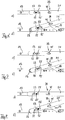
- Fig. 5 the scissor arm 15 is shown over its entire length from the wing-side end 29 articulated on the faceplate 13 to the frame-side end 27 arranged on the scissor bearing 26, the Figure 5a ) shows the parallel alignment of the scissor arm 15 relative to the faceplate 13 when the sash is closed or pivoted open, and the Figure 5b ) shows the pivoted position of the scissor arm 15 relative to the faceplate 13 when the sash is tilted open.
- the extension of the scissor arm 15 required for the tilt opening can clearly be seen in the fact that in the tilt-open state the support member 21 is offset from the pivot member 23 so far that the pivot member 23 protrudes below the support member 21.
- the forced displacement of the fork point 45 within the fork section 39 causes the sash to move slightly away from the axis of rotation D (in Fig. 5 to the left) and when tilting close slightly towards the axis of rotation D (in Fig. 5 to the right), as in Fig. 5 is illustrated by the distance d, which at the embodiment shown is about 4 mm.
- the relative position of the support member 21 relative to the intermediate member 25 generally does not change, which can be seen from the fact that the pins 53, 53 'maintain their position in the elongated holes 55, 55'.
- the 7a) and 7b ) each show a section of the Figure 5a ) or 5b).
- Corresponding excerpts are also in the Fig. 6a) and 6b ) as well as in the 8a) and 8b ) shown, with the Figures 6 to 8 differ from one another by the length of the scissor arm 15 set in each case. While the scissor arm is 15 in Fig. 7 is set to a medium length, the scissor arm is 15 in Fig. 6 especially short and in Fig. 8 Set particularly long, as can be seen from the corresponding position of the pins 53, 53 'in the elongated holes 55, 55'. This illustrates the flexible adaptability of the fitting arrangement 11 to possible deviations, in particular to possible misalignments of the sash.
- the length of the scissor arm 15 can be automatically adjusted in the tilt-open state and when the sash is rotated by offsetting the support member 21 relative to the intermediate member 25 in order to correct a misalignment of the sash.
- the joint displaceability of the support member 21 and the intermediate member 25 relative to the pivot member 23 enables the extension or shortening of the scissor arm 15 required for tilt opening and closing, so that the scissor arm 15 can be articulated at a fixed pivot point 19 on the faceplate 13 can.
Landscapes
- Engineering & Computer Science (AREA)
- Mechanical Engineering (AREA)
- Hinges (AREA)
Claims (11)
- Ensemble de ferrure (11) pour une fenêtre, une porte ou similaire, destiné à monter un battant sur un cadre de manière à pouvoir l'ouvrir par rotation autour d'un axe de rotation (D) et par basculement autour d'un axe de basculement,
comprenant une têtière (13), un bras de ciseaux (15) et une bielle de ciseaux (17),
dans lequel
la têtière (13) est réalisée pour être fixée sur un côté du battant éloigné de l'axe de basculement,
le bras de ciseaux (15) est réalisé pour être monté sur le cadre de manière à pouvoir tourner autour de l'axe de rotation (D) par une extrémité (27) située du côté cadre, en particulier par l'intermédiaire d'un palier de ciseaux (26), et est articulé à la têtière (13) par une extrémité (29) située du côté battant,
la bielle de ciseaux (17) est articulée à une portion de bifurcation (39) du bras de ciseaux (15) par une extrémité (37) côté bras et est articulée à la têtière (13) par une extrémité (35) côté battant,
le bras de ciseaux (15) est réalisé en au moins deux parties et comprend un élément porteur (21) sur lequel est formée l'extrémité (27) côté cadre du bras de ciseaux (15), et un élément pivotant (23) qui est séparé de celui-ci et sur lequel est formée l'extrémité (29) côté battant du bras de ciseaux (15),
l'élément porteur (21) et l'élément pivotant (23) peuvent être décalés l'un par rapport à l'autre, en particulier le long d'un axe longitudinal (L) du bras de ciseaux (15), de telle sorte que la distance entre la portion de bifurcation (39) et l'extrémité (29) côté battant du bras de ciseaux (15) est variable,
caractérisé en ce que
la bielle de ciseaux (17) est articulée par son extrémité (37) côté bras à un point de bifurcation (45) du bras de ciseaux (15), point qui est variable à l'intérieur de la portion de bifurcation (39), en particulier le long de l'axe longitudinal (L). - Ensemble de ferrure selon la revendication 1,
dans lequel
le bras de ciseaux (15) est articulé par son extrémité (29) côté battant à un point de basculement fixe (19) de la têtière (13), et/ou la bielle de ciseaux (17) est articulée par son extrémité (35) côté battant à un point de basculement fixe (19') de la têtière (13). - Ensemble de ferrure selon la revendication 1 ou 2,
dans lequel
le bras de ciseaux (15) et la bielle de ciseaux (17) coopèrent de telle manière que, en fonction de l'orientation angulaire relative respective du bras de ciseaux (15) et de la bielle de ciseaux (17), la variabilité du point de bifurcation (45) à l'intérieur de la portion de bifurcation (39) en direction de l'extrémité (29) côté battant du bras de ciseaux (15) est limitée du fait que soit
le bras de ciseaux (15) présente une coulisse de guidage (47) sur laquelle une portion de guidage (49) de la bielle de ciseaux (17) est guidée en fonction de l'orientation angulaire relative du bras de ciseaux (15) et de la bielle de ciseaux (17),
soit inversement,
la bielle de ciseaux (17) présente une coulisse de guidage sur laquelle est guidée une portion de guidage du bras de ciseaux (15) en fonction de l'orientation angulaire relative du bras de ciseaux (15) et de la bielle de ciseaux (17). - Ensemble de ferrure selon l'une au moins des revendications précédentes, dans lequel
une possibilité de basculement de la bielle de ciseaux (17) est limitée à une orientation pivotée maximale par une butée (51) réalisée en particulier sur le bras de ciseaux (15) ou sur la têtière (13). - Ensemble de ferrure selon l'une au moins des revendications précédentes, dans lequel
le bras de ciseaux (15) comprend en outre un élément intermédiaire (25) qui est couplé à l'élément porteur (21) et à l'élément pivotant (23) et qui peut être décalé par rapport à l'élément pivotant (23), en particulier le long de l'axe longitudinal (L), la portion de bifurcation (39) étant réalisée sur l'élément intermédiaire (25). - Ensemble de ferrure selon la revendication 5,
dans lequel
l'élément porteur (21) peut être décalé par rapport à l'élément intermédiaire (25), en particulier le long de l'axe longitudinal (L), et
des moyens de verrouillage (59) sont prévus entre l'élément porteur (21) et l'élément intermédiaire (25) pour fixer une position relative de l'élément porteur (21) et de l'élément intermédiaire (25). - Ensemble de ferrure selon la revendication 6,
dans lequel
les moyens de verrouillage (59) sont précontraints dans un état de fixation de la position relative de l'élément porteur (21) et de l'élément intermédiaire (25). - Ensemble de ferrure selon la revendication 6 ou 7,
dans lequel
les moyens de verrouillage (59) bloquent un décalage de l'élément porteur (21) par rapport à l'élément intermédiaire (25) dans une direction, en particulier en direction d'une augmentation de la distance entre la portion de bifurcation (39) et l'extrémité (27) côté cadre du bras de ciseaux (15), et le permettent dans une direction opposée à ladite direction. - Ensemble de ferrure selon l'une au moins des revendications 6 à 8,
dans lequel
les moyens de verrouillage (59) sont réalisés pour coopérer avec l'élément pivotant (23) en particulier de telle sorte qu'en fonction de la position relative de l'élément pivotant (23) et de l'élément intermédiaire (25), en particulier lorsqu'une distance maximale est atteinte entre la portion de bifurcation (39) et l'extrémité (29) côté battant du bras de ciseaux (15), ils sont déplacés dans un état permettant un décalage de l'élément porteur (21) par rapport à l'élément intermédiaire (25). - Ensemble de ferrure selon l'une au moins des revendications 6 à 9,
dans lequel
les moyens de verrouillage (59) sont réalisés sous la forme de dentures (61, 63) imbriquées, en particulier asymétriques, réalisées d'une part sur l'élément porteur (21) et d'autre par sur l'élément intermédiaire (25). - Fenêtre, porte ou similaire comportant un ensemble de ferrure (11) selon l'une au moins des revendications précédentes.
Priority Applications (1)
| Application Number | Priority Date | Filing Date | Title |
|---|---|---|---|
| PL17758526T PL3516143T3 (pl) | 2016-09-21 | 2017-08-28 | Układ okucia |
Applications Claiming Priority (2)
| Application Number | Priority Date | Filing Date | Title |
|---|---|---|---|
| DE102016117819.5A DE102016117819A1 (de) | 2016-09-21 | 2016-09-21 | Beschlaganordnung |
| PCT/EP2017/071506 WO2018054654A1 (fr) | 2016-09-21 | 2017-08-28 | Système de ferrure |
Publications (2)
| Publication Number | Publication Date |
|---|---|
| EP3516143A1 EP3516143A1 (fr) | 2019-07-31 |
| EP3516143B1 true EP3516143B1 (fr) | 2021-02-17 |
Family
ID=59738345
Family Applications (1)
| Application Number | Title | Priority Date | Filing Date |
|---|---|---|---|
| EP17758526.2A Active EP3516143B1 (fr) | 2016-09-21 | 2017-08-28 | Système de ferrure |
Country Status (4)
| Country | Link |
|---|---|
| EP (1) | EP3516143B1 (fr) |
| DE (1) | DE102016117819A1 (fr) |
| PL (1) | PL3516143T3 (fr) |
| WO (1) | WO2018054654A1 (fr) |
Cited By (1)
| Publication number | Priority date | Publication date | Assignee | Title |
|---|---|---|---|---|
| DE202023100930U1 (de) | 2023-02-28 | 2023-03-08 | Siegenia-Aubi Kg | Beschlaganordnung |
Family Cites Families (3)
| Publication number | Priority date | Publication date | Assignee | Title |
|---|---|---|---|---|
| DE7220339U (de) | 1973-06-28 | Schueco Schuermann H & Co | Scheren-, Ausstell- oder Feststellenker für Fenster, Türen od. dgl. | |
| DE19902150A1 (de) * | 1999-01-20 | 2000-07-27 | Winkhaus Fa August | Ausstellvorrichtung für einen an einem Rahmen schwenkbar angebrachten Kipp- oder Dreh-Kipp-Flügel |
| EP1710379A1 (fr) * | 2005-04-05 | 2006-10-11 | KALE Kapi Pencere Sistemleri Sanayi ve Ticaret A.S. | Cadre pour fenêtres et portes baculantes |
-
2016
- 2016-09-21 DE DE102016117819.5A patent/DE102016117819A1/de not_active Withdrawn
-
2017
- 2017-08-28 WO PCT/EP2017/071506 patent/WO2018054654A1/fr not_active Ceased
- 2017-08-28 EP EP17758526.2A patent/EP3516143B1/fr active Active
- 2017-08-28 PL PL17758526T patent/PL3516143T3/pl unknown
Non-Patent Citations (1)
| Title |
|---|
| None * |
Cited By (2)
| Publication number | Priority date | Publication date | Assignee | Title |
|---|---|---|---|---|
| DE202023100930U1 (de) | 2023-02-28 | 2023-03-08 | Siegenia-Aubi Kg | Beschlaganordnung |
| EP4424962A1 (fr) | 2023-02-28 | 2024-09-04 | Siegenia-Aubi KG | Ensemble ferrure |
Also Published As
| Publication number | Publication date |
|---|---|
| DE102016117819A1 (de) | 2018-03-22 |
| PL3516143T3 (pl) | 2021-08-02 |
| EP3516143A1 (fr) | 2019-07-31 |
| WO2018054654A1 (fr) | 2018-03-29 |
Similar Documents
| Publication | Publication Date | Title |
|---|---|---|
| EP3363976B1 (fr) | Dispositif de limitation d'ouverture rotative pour une fenêtre ou pour une porte permettant de limiter le mouvement d'ouverture rotatif d'un vantail d'une fenêtre ou d'une porte | |
| EP0678636B1 (fr) | Elément de connection pour l'installation du battant d'un vasistas de toiture dans le caisson d'entourage | |
| EP2708692B1 (fr) | Ferrure destinée à être agencée de façon cachée dans la feuillure entre un battant et un cadre de fenêtre, de porte ou analogue | |
| DE102007054476B4 (de) | Kulissenanordnung | |
| DE3637077C1 (de) | Scharniergelenk fuer Fenster,Tueren od.dgl. | |
| DE2460402A1 (de) | Ausstellvorrichtung fuer kipp- drehfluegel von fenstern, tueren od. dgl. | |
| WO2017157611A1 (fr) | Dispositif de projection du battant d'une fenêtre ou d'une porte qui peut être amené au moins dans une position de rangement parallèle et qui est apte à coulisser horizontalement dans cette position | |
| EP2902575B1 (fr) | Système de ferrure | |
| EP1936086B1 (fr) | Palier d'angle pour fenêtres, portes ou analogues | |
| CH657659A5 (de) | Drehkippfenster oder drehkipptuer mit einem seitenscharnier und einem ausstellarm. | |
| EP2703587B1 (fr) | Ferrure destinée à être agencée de façon cachée dans la feuillure entre un battant et un cadre de fenêtre, de porte ou analogue | |
| DE1810671A1 (de) | Stelleinrichtung an Fenstern,Tueren od.dgl. | |
| WO2018054654A1 (fr) | Système de ferrure | |
| DE2658626B2 (de) | Schaltsperre für Treibstangenbeschläge | |
| DE3912387C1 (en) | Concealed fitting for hinged window - incorporates system of pins and guide rods | |
| WO2001098612A1 (fr) | Ferrure oscillobattante | |
| DE8103368U1 (de) | Drehkippfenster oder -tür | |
| DE2727585C2 (de) | Nachstellbares Lenker-Drehlager für Kipp-Schwenkfenster oder -türen | |
| EP0980949B1 (fr) | Porte pourvu d'un dispositif d'ancrage pour ancrer une charnière de porte dans un chassis | |
| EP0703339B1 (fr) | Fenêtre ou porte pivotante ou pivotante et basculante | |
| EP1715125A2 (fr) | Ferrures pour fenêtre oscillobattante avec une position pour créer une fente de ventilation | |
| DE2932865A1 (de) | Beschlag fuer dachfenster | |
| EP4484690A1 (fr) | Palier d'angle avec boulon de support chanfreiné et excentrique | |
| DE102016108953A1 (de) | Beschlaganordnung | |
| DE102014004593A1 (de) | Dreh-Kipp-Beschlag für ein Fenster, eine Tür oder dergleichen, sowie Fenster, Tür oder dergleichen mit einem Dreh-Kipp-Beschlag |
Legal Events
| Date | Code | Title | Description |
|---|---|---|---|
| STAA | Information on the status of an ep patent application or granted ep patent |
Free format text: STATUS: UNKNOWN |
|
| STAA | Information on the status of an ep patent application or granted ep patent |
Free format text: STATUS: THE INTERNATIONAL PUBLICATION HAS BEEN MADE |
|
| PUAI | Public reference made under article 153(3) epc to a published international application that has entered the european phase |
Free format text: ORIGINAL CODE: 0009012 |
|
| STAA | Information on the status of an ep patent application or granted ep patent |
Free format text: STATUS: REQUEST FOR EXAMINATION WAS MADE |
|
| 17P | Request for examination filed |
Effective date: 20190321 |
|
| AK | Designated contracting states |
Kind code of ref document: A1 Designated state(s): AL AT BE BG CH CY CZ DE DK EE ES FI FR GB GR HR HU IE IS IT LI LT LU LV MC MK MT NL NO PL PT RO RS SE SI SK SM TR |
|
| AX | Request for extension of the european patent |
Extension state: BA ME |
|
| RIN1 | Information on inventor provided before grant (corrected) |
Inventor name: DUCHAC, ROBIN |
|
| DAV | Request for validation of the european patent (deleted) | ||
| DAX | Request for extension of the european patent (deleted) | ||
| GRAP | Despatch of communication of intention to grant a patent |
Free format text: ORIGINAL CODE: EPIDOSNIGR1 |
|
| STAA | Information on the status of an ep patent application or granted ep patent |
Free format text: STATUS: GRANT OF PATENT IS INTENDED |
|
| INTG | Intention to grant announced |
Effective date: 20200519 |
|
| GRAS | Grant fee paid |
Free format text: ORIGINAL CODE: EPIDOSNIGR3 |
|
| GRAJ | Information related to disapproval of communication of intention to grant by the applicant or resumption of examination proceedings by the epo deleted |
Free format text: ORIGINAL CODE: EPIDOSDIGR1 |
|
| GRAL | Information related to payment of fee for publishing/printing deleted |
Free format text: ORIGINAL CODE: EPIDOSDIGR3 |
|
| STAA | Information on the status of an ep patent application or granted ep patent |
Free format text: STATUS: REQUEST FOR EXAMINATION WAS MADE |
|
| INTC | Intention to grant announced (deleted) | ||
| GRAP | Despatch of communication of intention to grant a patent |
Free format text: ORIGINAL CODE: EPIDOSNIGR1 |
|
| STAA | Information on the status of an ep patent application or granted ep patent |
Free format text: STATUS: GRANT OF PATENT IS INTENDED |
|
| INTG | Intention to grant announced |
Effective date: 20201120 |
|
| GRAA | (expected) grant |
Free format text: ORIGINAL CODE: 0009210 |
|
| STAA | Information on the status of an ep patent application or granted ep patent |
Free format text: STATUS: THE PATENT HAS BEEN GRANTED |
|
| AK | Designated contracting states |
Kind code of ref document: B1 Designated state(s): AL AT BE BG CH CY CZ DE DK EE ES FI FR GB GR HR HU IE IS IT LI LT LU LV MC MK MT NL NO PL PT RO RS SE SI SK SM TR |
|
| REG | Reference to a national code |
Ref country code: GB Ref legal event code: FG4D Free format text: NOT ENGLISH |
|
| REG | Reference to a national code |
Ref country code: CH Ref legal event code: EP |
|
| REG | Reference to a national code |
Ref country code: DE Ref legal event code: R096 Ref document number: 502017009365 Country of ref document: DE |
|
| REG | Reference to a national code |
Ref country code: AT Ref legal event code: REF Ref document number: 1361677 Country of ref document: AT Kind code of ref document: T Effective date: 20210315 |
|
| REG | Reference to a national code |
Ref country code: IE Ref legal event code: FG4D Free format text: LANGUAGE OF EP DOCUMENT: GERMAN |
|
| REG | Reference to a national code |
Ref country code: LT Ref legal event code: MG9D |
|
| REG | Reference to a national code |
Ref country code: NL Ref legal event code: MP Effective date: 20210217 |
|
| PG25 | Lapsed in a contracting state [announced via postgrant information from national office to epo] |
Ref country code: BG Free format text: LAPSE BECAUSE OF FAILURE TO SUBMIT A TRANSLATION OF THE DESCRIPTION OR TO PAY THE FEE WITHIN THE PRESCRIBED TIME-LIMIT Effective date: 20210517 Ref country code: LT Free format text: LAPSE BECAUSE OF FAILURE TO SUBMIT A TRANSLATION OF THE DESCRIPTION OR TO PAY THE FEE WITHIN THE PRESCRIBED TIME-LIMIT Effective date: 20210217 Ref country code: HR Free format text: LAPSE BECAUSE OF FAILURE TO SUBMIT A TRANSLATION OF THE DESCRIPTION OR TO PAY THE FEE WITHIN THE PRESCRIBED TIME-LIMIT Effective date: 20210217 Ref country code: GR Free format text: LAPSE BECAUSE OF FAILURE TO SUBMIT A TRANSLATION OF THE DESCRIPTION OR TO PAY THE FEE WITHIN THE PRESCRIBED TIME-LIMIT Effective date: 20210518 Ref country code: FI Free format text: LAPSE BECAUSE OF FAILURE TO SUBMIT A TRANSLATION OF THE DESCRIPTION OR TO PAY THE FEE WITHIN THE PRESCRIBED TIME-LIMIT Effective date: 20210217 Ref country code: NO Free format text: LAPSE BECAUSE OF FAILURE TO SUBMIT A TRANSLATION OF THE DESCRIPTION OR TO PAY THE FEE WITHIN THE PRESCRIBED TIME-LIMIT Effective date: 20210517 Ref country code: PT Free format text: LAPSE BECAUSE OF FAILURE TO SUBMIT A TRANSLATION OF THE DESCRIPTION OR TO PAY THE FEE WITHIN THE PRESCRIBED TIME-LIMIT Effective date: 20210617 |
|
| PG25 | Lapsed in a contracting state [announced via postgrant information from national office to epo] |
Ref country code: SE Free format text: LAPSE BECAUSE OF FAILURE TO SUBMIT A TRANSLATION OF THE DESCRIPTION OR TO PAY THE FEE WITHIN THE PRESCRIBED TIME-LIMIT Effective date: 20210217 Ref country code: RS Free format text: LAPSE BECAUSE OF FAILURE TO SUBMIT A TRANSLATION OF THE DESCRIPTION OR TO PAY THE FEE WITHIN THE PRESCRIBED TIME-LIMIT Effective date: 20210217 Ref country code: LV Free format text: LAPSE BECAUSE OF FAILURE TO SUBMIT A TRANSLATION OF THE DESCRIPTION OR TO PAY THE FEE WITHIN THE PRESCRIBED TIME-LIMIT Effective date: 20210217 Ref country code: NL Free format text: LAPSE BECAUSE OF FAILURE TO SUBMIT A TRANSLATION OF THE DESCRIPTION OR TO PAY THE FEE WITHIN THE PRESCRIBED TIME-LIMIT Effective date: 20210217 |
|
| PG25 | Lapsed in a contracting state [announced via postgrant information from national office to epo] |
Ref country code: IS Free format text: LAPSE BECAUSE OF FAILURE TO SUBMIT A TRANSLATION OF THE DESCRIPTION OR TO PAY THE FEE WITHIN THE PRESCRIBED TIME-LIMIT Effective date: 20210617 |
|
| PG25 | Lapsed in a contracting state [announced via postgrant information from national office to epo] |
Ref country code: EE Free format text: LAPSE BECAUSE OF FAILURE TO SUBMIT A TRANSLATION OF THE DESCRIPTION OR TO PAY THE FEE WITHIN THE PRESCRIBED TIME-LIMIT Effective date: 20210217 Ref country code: CZ Free format text: LAPSE BECAUSE OF FAILURE TO SUBMIT A TRANSLATION OF THE DESCRIPTION OR TO PAY THE FEE WITHIN THE PRESCRIBED TIME-LIMIT Effective date: 20210217 Ref country code: SM Free format text: LAPSE BECAUSE OF FAILURE TO SUBMIT A TRANSLATION OF THE DESCRIPTION OR TO PAY THE FEE WITHIN THE PRESCRIBED TIME-LIMIT Effective date: 20210217 |
|
| REG | Reference to a national code |
Ref country code: DE Ref legal event code: R097 Ref document number: 502017009365 Country of ref document: DE |
|
| PG25 | Lapsed in a contracting state [announced via postgrant information from national office to epo] |
Ref country code: SK Free format text: LAPSE BECAUSE OF FAILURE TO SUBMIT A TRANSLATION OF THE DESCRIPTION OR TO PAY THE FEE WITHIN THE PRESCRIBED TIME-LIMIT Effective date: 20210217 Ref country code: DK Free format text: LAPSE BECAUSE OF FAILURE TO SUBMIT A TRANSLATION OF THE DESCRIPTION OR TO PAY THE FEE WITHIN THE PRESCRIBED TIME-LIMIT Effective date: 20210217 Ref country code: RO Free format text: LAPSE BECAUSE OF FAILURE TO SUBMIT A TRANSLATION OF THE DESCRIPTION OR TO PAY THE FEE WITHIN THE PRESCRIBED TIME-LIMIT Effective date: 20210217 |
|
| PLBE | No opposition filed within time limit |
Free format text: ORIGINAL CODE: 0009261 |
|
| STAA | Information on the status of an ep patent application or granted ep patent |
Free format text: STATUS: NO OPPOSITION FILED WITHIN TIME LIMIT |
|
| 26N | No opposition filed |
Effective date: 20211118 |
|
| PG25 | Lapsed in a contracting state [announced via postgrant information from national office to epo] |
Ref country code: ES Free format text: LAPSE BECAUSE OF FAILURE TO SUBMIT A TRANSLATION OF THE DESCRIPTION OR TO PAY THE FEE WITHIN THE PRESCRIBED TIME-LIMIT Effective date: 20210217 Ref country code: AL Free format text: LAPSE BECAUSE OF FAILURE TO SUBMIT A TRANSLATION OF THE DESCRIPTION OR TO PAY THE FEE WITHIN THE PRESCRIBED TIME-LIMIT Effective date: 20210217 |
|
| PG25 | Lapsed in a contracting state [announced via postgrant information from national office to epo] |
Ref country code: SI Free format text: LAPSE BECAUSE OF FAILURE TO SUBMIT A TRANSLATION OF THE DESCRIPTION OR TO PAY THE FEE WITHIN THE PRESCRIBED TIME-LIMIT Effective date: 20210217 |
|
| REG | Reference to a national code |
Ref country code: CH Ref legal event code: PL |
|
| PG25 | Lapsed in a contracting state [announced via postgrant information from national office to epo] |
Ref country code: MC Free format text: LAPSE BECAUSE OF FAILURE TO SUBMIT A TRANSLATION OF THE DESCRIPTION OR TO PAY THE FEE WITHIN THE PRESCRIBED TIME-LIMIT Effective date: 20210217 |
|
| REG | Reference to a national code |
Ref country code: BE Ref legal event code: MM Effective date: 20210831 |
|
| GBPC | Gb: european patent ceased through non-payment of renewal fee |
Effective date: 20210828 |
|
| PG25 | Lapsed in a contracting state [announced via postgrant information from national office to epo] |
Ref country code: LI Free format text: LAPSE BECAUSE OF NON-PAYMENT OF DUE FEES Effective date: 20210831 Ref country code: CH Free format text: LAPSE BECAUSE OF NON-PAYMENT OF DUE FEES Effective date: 20210831 |
|
| PG25 | Lapsed in a contracting state [announced via postgrant information from national office to epo] |
Ref country code: IS Free format text: LAPSE BECAUSE OF FAILURE TO SUBMIT A TRANSLATION OF THE DESCRIPTION OR TO PAY THE FEE WITHIN THE PRESCRIBED TIME-LIMIT Effective date: 20210617 Ref country code: LU Free format text: LAPSE BECAUSE OF NON-PAYMENT OF DUE FEES Effective date: 20210828 |
|
| PG25 | Lapsed in a contracting state [announced via postgrant information from national office to epo] |
Ref country code: IE Free format text: LAPSE BECAUSE OF NON-PAYMENT OF DUE FEES Effective date: 20210828 Ref country code: GB Free format text: LAPSE BECAUSE OF NON-PAYMENT OF DUE FEES Effective date: 20210828 Ref country code: BE Free format text: LAPSE BECAUSE OF NON-PAYMENT OF DUE FEES Effective date: 20210831 |
|
| PG25 | Lapsed in a contracting state [announced via postgrant information from national office to epo] |
Ref country code: CY Free format text: LAPSE BECAUSE OF FAILURE TO SUBMIT A TRANSLATION OF THE DESCRIPTION OR TO PAY THE FEE WITHIN THE PRESCRIBED TIME-LIMIT Effective date: 20210217 |
|
| PG25 | Lapsed in a contracting state [announced via postgrant information from national office to epo] |
Ref country code: HU Free format text: LAPSE BECAUSE OF FAILURE TO SUBMIT A TRANSLATION OF THE DESCRIPTION OR TO PAY THE FEE WITHIN THE PRESCRIBED TIME-LIMIT; INVALID AB INITIO Effective date: 20170828 |
|
| REG | Reference to a national code |
Ref country code: AT Ref legal event code: MM01 Ref document number: 1361677 Country of ref document: AT Kind code of ref document: T Effective date: 20220828 |
|
| PG25 | Lapsed in a contracting state [announced via postgrant information from national office to epo] |
Ref country code: AT Free format text: LAPSE BECAUSE OF NON-PAYMENT OF DUE FEES Effective date: 20220828 |
|
| PG25 | Lapsed in a contracting state [announced via postgrant information from national office to epo] |
Ref country code: MK Free format text: LAPSE BECAUSE OF FAILURE TO SUBMIT A TRANSLATION OF THE DESCRIPTION OR TO PAY THE FEE WITHIN THE PRESCRIBED TIME-LIMIT Effective date: 20210217 |
|
| PG25 | Lapsed in a contracting state [announced via postgrant information from national office to epo] |
Ref country code: TR Free format text: LAPSE BECAUSE OF FAILURE TO SUBMIT A TRANSLATION OF THE DESCRIPTION OR TO PAY THE FEE WITHIN THE PRESCRIBED TIME-LIMIT Effective date: 20210217 |
|
| PG25 | Lapsed in a contracting state [announced via postgrant information from national office to epo] |
Ref country code: MT Free format text: LAPSE BECAUSE OF FAILURE TO SUBMIT A TRANSLATION OF THE DESCRIPTION OR TO PAY THE FEE WITHIN THE PRESCRIBED TIME-LIMIT Effective date: 20210217 |
|
| PGFP | Annual fee paid to national office [announced via postgrant information from national office to epo] |
Ref country code: DE Payment date: 20250820 Year of fee payment: 9 |
|
| PGFP | Annual fee paid to national office [announced via postgrant information from national office to epo] |
Ref country code: PL Payment date: 20250818 Year of fee payment: 9 Ref country code: IT Payment date: 20250825 Year of fee payment: 9 |
|
| PGFP | Annual fee paid to national office [announced via postgrant information from national office to epo] |
Ref country code: FR Payment date: 20250828 Year of fee payment: 9 |