EP3516201B1 - Verfahren zum entwässern eines betriebsstoffs sowie entwässerungseinrichtung - Google Patents
Verfahren zum entwässern eines betriebsstoffs sowie entwässerungseinrichtung Download PDFInfo
- Publication number
- EP3516201B1 EP3516201B1 EP17801373.6A EP17801373A EP3516201B1 EP 3516201 B1 EP3516201 B1 EP 3516201B1 EP 17801373 A EP17801373 A EP 17801373A EP 3516201 B1 EP3516201 B1 EP 3516201B1
- Authority
- EP
- European Patent Office
- Prior art keywords
- water
- operating medium
- fuel
- dewatering
- case
- Prior art date
- Legal status (The legal status is an assumption and is not a legal conclusion. Google has not performed a legal analysis and makes no representation as to the accuracy of the status listed.)
- Active
Links
Images

Classifications
-
- F—MECHANICAL ENGINEERING; LIGHTING; HEATING; WEAPONS; BLASTING
- F02—COMBUSTION ENGINES; HOT-GAS OR COMBUSTION-PRODUCT ENGINE PLANTS
- F02M—SUPPLYING COMBUSTION ENGINES IN GENERAL WITH COMBUSTIBLE MIXTURES OR CONSTITUENTS THEREOF
- F02M37/00—Apparatus or systems for feeding liquid fuel from storage containers to carburettors or fuel-injection apparatus; Arrangements for purifying liquid fuel specially adapted for, or arranged on, internal-combustion engines
- F02M37/0047—Layout or arrangement of systems for feeding fuel
- F02M37/007—Layout or arrangement of systems for feeding fuel characterised by its use in vehicles, in stationary plants or in small engines, e.g. hand held tools
-
- B—PERFORMING OPERATIONS; TRANSPORTING
- B01—PHYSICAL OR CHEMICAL PROCESSES OR APPARATUS IN GENERAL
- B01D—SEPARATION
- B01D17/00—Separation of liquids, not provided for elsewhere, e.g. by thermal diffusion
- B01D17/02—Separation of non-miscible liquids
- B01D17/0208—Separation of non-miscible liquids by sedimentation
- B01D17/0214—Separation of non-miscible liquids by sedimentation with removal of one of the phases
-
- F—MECHANICAL ENGINEERING; LIGHTING; HEATING; WEAPONS; BLASTING
- F02—COMBUSTION ENGINES; HOT-GAS OR COMBUSTION-PRODUCT ENGINE PLANTS
- F02M—SUPPLYING COMBUSTION ENGINES IN GENERAL WITH COMBUSTIBLE MIXTURES OR CONSTITUENTS THEREOF
- F02M37/00—Apparatus or systems for feeding liquid fuel from storage containers to carburettors or fuel-injection apparatus; Arrangements for purifying liquid fuel specially adapted for, or arranged on, internal-combustion engines
- F02M37/22—Arrangements for purifying liquid fuel specially adapted for, or arranged on, internal-combustion engines, e.g. arrangements in the feeding system
- F02M37/24—Arrangements for purifying liquid fuel specially adapted for, or arranged on, internal-combustion engines, e.g. arrangements in the feeding system characterised by water separating means
-
- F—MECHANICAL ENGINEERING; LIGHTING; HEATING; WEAPONS; BLASTING
- F02—COMBUSTION ENGINES; HOT-GAS OR COMBUSTION-PRODUCT ENGINE PLANTS
- F02M—SUPPLYING COMBUSTION ENGINES IN GENERAL WITH COMBUSTIBLE MIXTURES OR CONSTITUENTS THEREOF
- F02M37/00—Apparatus or systems for feeding liquid fuel from storage containers to carburettors or fuel-injection apparatus; Arrangements for purifying liquid fuel specially adapted for, or arranged on, internal-combustion engines
- F02M37/22—Arrangements for purifying liquid fuel specially adapted for, or arranged on, internal-combustion engines, e.g. arrangements in the feeding system
- F02M37/24—Arrangements for purifying liquid fuel specially adapted for, or arranged on, internal-combustion engines, e.g. arrangements in the feeding system characterised by water separating means
- F02M37/26—Arrangements for purifying liquid fuel specially adapted for, or arranged on, internal-combustion engines, e.g. arrangements in the feeding system characterised by water separating means with water detection means
- F02M37/28—Arrangements for purifying liquid fuel specially adapted for, or arranged on, internal-combustion engines, e.g. arrangements in the feeding system characterised by water separating means with water detection means with means activated by the presence of water, e.g. alarms or means for automatic drainage
-
- F—MECHANICAL ENGINEERING; LIGHTING; HEATING; WEAPONS; BLASTING
- F02—COMBUSTION ENGINES; HOT-GAS OR COMBUSTION-PRODUCT ENGINE PLANTS
- F02M—SUPPLYING COMBUSTION ENGINES IN GENERAL WITH COMBUSTIBLE MIXTURES OR CONSTITUENTS THEREOF
- F02M37/00—Apparatus or systems for feeding liquid fuel from storage containers to carburettors or fuel-injection apparatus; Arrangements for purifying liquid fuel specially adapted for, or arranged on, internal-combustion engines
- F02M37/22—Arrangements for purifying liquid fuel specially adapted for, or arranged on, internal-combustion engines, e.g. arrangements in the feeding system
- F02M37/32—Arrangements for purifying liquid fuel specially adapted for, or arranged on, internal-combustion engines, e.g. arrangements in the feeding system characterised by filters or filter arrangements
-
- B—PERFORMING OPERATIONS; TRANSPORTING
- B01—PHYSICAL OR CHEMICAL PROCESSES OR APPARATUS IN GENERAL
- B01D—SEPARATION
- B01D2221/00—Applications of separation devices
- B01D2221/08—Mobile separation devices
-
- B—PERFORMING OPERATIONS; TRANSPORTING
- B01—PHYSICAL OR CHEMICAL PROCESSES OR APPARATUS IN GENERAL
- B01D—SEPARATION
- B01D2257/00—Components to be removed
- B01D2257/80—Water
-
- B—PERFORMING OPERATIONS; TRANSPORTING
- B60—VEHICLES IN GENERAL
- B60K—ARRANGEMENT OR MOUNTING OF PROPULSION UNITS OR OF TRANSMISSIONS IN VEHICLES; ARRANGEMENT OR MOUNTING OF PLURAL DIVERSE PRIME-MOVERS IN VEHICLES; AUXILIARY DRIVES FOR VEHICLES; INSTRUMENTATION OR DASHBOARDS FOR VEHICLES; ARRANGEMENTS IN CONNECTION WITH COOLING, AIR INTAKE, GAS EXHAUST OR FUEL SUPPLY OF PROPULSION UNITS IN VEHICLES
- B60K15/00—Arrangement in connection with fuel supply of combustion engines or other fuel consuming energy converters, e.g. fuel cells; Mounting or construction of fuel tanks
- B60K15/03—Fuel tanks
- B60K15/077—Fuel tanks with means modifying or controlling distribution or motion of fuel, e.g. to prevent noise, surge, splash or fuel starvation
- B60K2015/0772—Floats in the fuel tank
-
- F—MECHANICAL ENGINEERING; LIGHTING; HEATING; WEAPONS; BLASTING
- F02—COMBUSTION ENGINES; HOT-GAS OR COMBUSTION-PRODUCT ENGINE PLANTS
- F02M—SUPPLYING COMBUSTION ENGINES IN GENERAL WITH COMBUSTIBLE MIXTURES OR CONSTITUENTS THEREOF
- F02M37/00—Apparatus or systems for feeding liquid fuel from storage containers to carburettors or fuel-injection apparatus; Arrangements for purifying liquid fuel specially adapted for, or arranged on, internal-combustion engines
- F02M37/0076—Details of the fuel feeding system related to the fuel tank
- F02M37/0082—Devices inside the fuel tank other than fuel pumps or filters
Definitions
- the invention relates to a method for dewatering an operating material, in particular a fuel, preferably during operation of a vehicle, in particular a rail vehicle.
- the invention further relates to a dewatering device for a fuel, in particular a fuel.
- a rail vehicle in particular a diesel locomotive (traction vehicle)
- traction vehicle there is the problem that there may be too much water in an operating material, in particular a fuel.
- Water is introduced into the operating fluid e.g. via tank depots, a defective filler cap, condensation, etc., with too much water inevitably leading to damage, in particular engine damage.
- the fuel is taken from a fuel tank below with the aim of minimizing silting.
- water deposited in the fuel tank is also conveyed into a filter and in the direction of an internal combustion engine of the rail vehicle.
- a fuel supply device for an internal combustion engine has a high-pressure pump, through which fuel is conveyed to an injection point on a cylinder internal combustion engine.
- the high-pressure pump is preceded by a separation device through which water contained in the fuel is separated. Water separated by the separation device is fed at least indirectly to the exhaust gas flow of the internal combustion engine.
- an unwanted delivery of water to the engine is to be avoided in order to prevent damage to the engine of the vehicle.
- fuel is dewatered during operation of a rail vehicle.
- the fuel is pumped out of a fuel tank as fuel.
- Water present in the operating fluid is separated into a water tank.
- the water is conveyed from the water tank back into the fuel tank when the water tank is essentially full.
- the water is conveyed from the water tank into an exhaust system when an exhaust gas volume flow is at least sufficient and when the water tank is essentially filled, the water which is fed into the exhaust system being evaporated in the hot exhaust gas stream and released into a local environment.
- the water is preferably in droplet form in the operating fluid.
- a water container is to be understood as a partially closed space (vessel) which is suitable for collecting a certain amount of water.
- the water tank need not be specifically designed as a water tank; a room to collect water is sufficient.
- the water container can also be a section of a fuel filter, such as a fuel pre-filter. It is of course possible to design the water tank specifically as such. In the case of the fuel filter, this can be a hollow area of a housing of the fuel filter in which, for example, there is no filter material.
- water is conveyed into the fuel tank at the bottom by means of a water conveying device.
- water is conveyed into the exhaust system by means of a water delivery device.
- a water delivery device I.e. Liquid water is preferably added to a hot exhaust gas stream in an exhaust silencer of the exhaust system, evaporated there and released into an environment.
- a drainage device or an outlet of the drainage device on / in the exhaust system can optionally also be designed as a vacuum pump.
- the water delivery device is designed in particular as a drainage pump.
- water is drained out of the fuel tank, out of the water container, out of a drainage line and / or out of a water delivery device.
- fuel is conveyed out of the fuel tank substantially at the level of the fuel in the fuel tank. This is preferably done by means of an operating fluid intake float and preferably by means of a flexible operating fluid hose on the operating fluid intake float.
- water present in a fuel supply device of the engine is drained off before fueling or starting up an engine.
- the fuel is delivered to the internal combustion engine.
- Water is conveyed out of the water tank by means of the water delivery device, in particular a drainage pump.
- the water delivery device can operate in a sensor-signal-controlled manner, temporarily, in an adjustable manner, or permanently.
- the drainage device according to the invention for a fuel of a rail vehicle is designed to carry out the drainage method described above. It has a water tank in which water present in the operating material can be separated.
- the drainage device has a drainage line, which leads from the water tank to a fuel tank and to an exhaust system.
- the drainage line has an inlet line to a water delivery device and both a return line from the water delivery device to the fuel tank and a feed line from the water delivery device to the exhaust system, the return line being fluid-mechanically coupled to the delivery line.
- the water delivery device essentially directly on the water tank, on the fuel tank or on the exhaust system.
- the supply line, the return line and / or the supply line, or even the drainage line itself is omitted, apart from a connection or connections in question.
- the corresponding line is then substituted by the water pumping device or its connection.
- the water tank, the fuel tank, the drainage line and / or the water delivery device can have a water removal point. If the drainage line has at least one water removal point, this can be provided on the feed line, the return line and / or the feed line.
- the water withdrawal point can e.g. as a manually or electromechanically operated drain valve, e.g. a drain cock.
- the fuel preferably comes from the fuel tank.
- the water tank can be part of a fuel filter of the vehicle, preferably part of a fuel filter of the vehicle.
- the drainage line or the feed line, the return line and / or the feed line can have an adjusting means.
- the return means and / or the flow of the water can be prevented by means of the adjusting means (check valve).
- the dewatering device can be designed in such a way that fuel can be conveyed out of the fuel tank by means of a fuel suction float in the fuel tank that can float on the fuel and preferably by means of a particularly flexible fuel hose in the fuel tank.
- a fuel supply device which has the dewatering device, is designed such that the fuel can subsequently be conveyed into a fuel filter, preferably a fuel pre-filter, and into an internal combustion engine. If a fuel prefilter is used, a main fuel filter is preferably also provided between the fuel prefilter and the internal combustion engine.
- the fuel supply device has a fuel tank, fuel in the fuel tank being able to be conveyed out of the fuel tank in the fuel tank by means of a fuel suction float that can float on top of the fuel.
- the operating fluid intake float can have a preferably flexible operating fluid hose, by means of which operating fluid can be conveyed out of the operating fluid tank.
- the fluid hose can be further contacted mechanically, for example at the top, middle or bottom in / on the fluid tank, for which the fuel tank can have a corresponding connection. It is also possible for the fuel hose to pass through a wall of the fuel tank and for further fluid-mechanical contact outside of the fuel tank.
- the fuel supply device can have a fuel supply device downstream of the fuel intake float or the fuel hose.
- the fuel supply device in particular a fuel pump, is preferably provided outside the fuel tank.
- the fuel supply device can furthermore have a fuel filter, in particular a fuel pre-filter and / or a fuel filter, and corresponding fuel lines.
- the fuel tank can have a water withdrawal point.
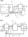
- the invention is based on exemplary embodiments of an embodiment of a variant of a fuel supply device 0 (cf. FIG 1 ) and of three embodiments of a variant (cf. the 1 to 3 ) a drainage device 10 for a rail vehicle explained in more detail.
- a drainage device can thus be used on all internal combustion engines, in particular diesel engines. This applies, for example, to engines in power generators, trucks, military vehicles, rail vehicles, ships, etc. Furthermore, the invention is applicable to all areas which have to reckon with contaminated diesel fuels, such as in mining, on construction sites, etc. Relevant manufacturers are, for example, engine manufacturers; Engine suppliers, eg filter manufacturers; Commercial vehicle manufacturers; Generator set manufacturers; Manufacturer of marine engines etc.
- the FIG 1 shows the fuel supply device 0 according to the invention, preferably designed as a fuel supply device 0, the supply device 0 having at least one fuel tank 20, in particular a fuel tank 20, preferably with an inner protective coating or an internal phosphating.
- a level 22 or level 22 of a fuel 2, in particular a fuel 2 is with a triangle 22 in the FIG 1 marked.
- Air 3 is usually located above it.
- the fuel 2 can be removed from the fuel tank 20 by means of a fuel suction float 210 (fuel suction float 210) that can float on the fuel 2, and in particular can be conveyed away from the suction float 210 through a preferably at least partially flexible fuel hose 212 (fuel hose 212) .
- the fuel hose 212 is preferably connected to the intake float 210 in a fluid-mechanical manner.
- Further fluid-mechanical contacting of the fuel hose 212 can take place at a connection which is preferably located inside the fuel tank 20, or the fuel hose 212 is guided to the outside and further fluid-mechanically contacted on the fuel tank 20 or another device, such as a fuel filter 40 (fuel filter 40).
- the fuel hose 212 can lead to a fuel line Lead 300 (fuel line 300) that connects the fuel intake float 210 with the fuel filter 40 fluid mechanically.
- the supply device 0 downstream of the fuel intake float 210, in particular downstream of the fuel hose 212 can have a fuel delivery device (fuel delivery device).
- the supply device 0, apart from connections etc., the fuel filter 40, preferably a fuel prefilter 40 (fuel prefilter 40) and / or a main fuel filter (main fuel filter) and a fuel line 500 (fuel line 500) from the fuel filter 40 to an internal combustion engine 60, in particular a diesel engine 60 of the rail vehicle.
- a fuel prefilter 40 fuel prefilter 40
- main fuel filter main fuel filter
- a fuel line 500 fuel line 500 from the fuel filter 40 to an internal combustion engine 60, in particular a diesel engine 60 of the rail vehicle.
- the fuel 2 in the fuel tank 20 can be sucked into the fuel filter 40 via the suction float 210 on a surface or in a surface area of the fuel 2, as a result of which, in comparison with a lower suction area (prior art) only a small amount of water is separated in the fuel filter 40 (see below).
- water 1 separated in a water tank 410 is returned to a fuel tank 20 ( FIG 1 ). Furthermore, in a preferred embodiment, water 1 separated in the water tank 410 can be conveyed further into an exhaust system 80, where it evaporates in a stream of a hot exhaust gas 4, preferably in an exhaust gas muffler 80, and a water vapor formed is released into a local environment ( FIG 2 ). Furthermore, in a preferred embodiment, water 1 separated in the water tank 410 can be returned to the fuel tank 20 and separated water 1 (from the fuel tank 20 or the Water tank 410) are conveyed into the exhaust system 80 ( FIG 3 ).
- the 1 to 3 each show an embodiment of the drainage device 10 of a fuel 2 (fuel 2) of the rail vehicle or of its fuel supply device 0.
- the drainage device 10 essentially comprises a drainage line 100 which leads from a water tank 410 to a fuel tank 20 (fuel tank 20) and / or leads from the water tank 410 to an exhaust system 80, in particular an exhaust silencer 80.
- the drainage line 100 can have a water removal point 120, optionally with a drainage control means (for example a drainage valve, drain cock, which can be operated manually or electromechanically).
- the drainage device 10 or the drainage line 100 has a water delivery device 110, in particular a drainage pump 110.
- the water tank 410 can be a part or a section of a fuel filter 40 (fuel filter 40), preferably a fuel prefilter 40 (fuel prefilter 40).
- the water conveying device 110 can have a water removal point (not shown), optionally with a drainage control means (e.g. drainage valve, drain cock, manually or electromechanically actuable).
- a drainage control means e.g. drainage valve, drain cock, manually or electromechanically actuable
- the fuel tank 20 and / or the water container 410 can have a water removal point 220, 420, if necessary in each case with a drainage control means (e.g. drainage valve, drain cock, manually or electromechanically actuable).
- water 1 separated in the water tank 410 can be returned to / into the fuel tank 20 and / or forward to / into the exhaust system 80 are funded.
- the fuel tank 20 can also be brought into fluid mechanical contact with the exhaust system 80.
- the FIG 1 shows the first embodiment of the dewatering device 10 in addition to the fuel supply device 0.
- the dewatering line 100 comprises an inlet line 101 and only one return line 102.
- the inlet line 101 leads from the water tank 410 to the water delivery device 110 / into the return line 102.
- the return line 102 leads from the Inlet line 101 / from the water delivery device 110 back to / into the fuel tank 20.
- the inlet line (101) can be designed as a section of the return line 102 or vice versa.
- the water tank 410 and / or the inlet line 101 (preferably) has a water removal point 120, 420.
- the water tank 410 preferably has a water tank sensor 430 or water tank detector 430 which, depending on a level or level of water 1 in the water tank 410, outputs a sensor signal S1.
- the water tank sensor 430 is a threshold value sensor.
- the preferably maintenance-free drainage pump 110 conveys water 1 below from the water tank 410 directly down into the fuel tank 20 via a sensor signal S1, for example, 'water tank full' (water tank 410 filled sufficiently or essentially with water 1). By returning the water 1 to the bottom of the fuel tank 20, a settled sludge in the fuel 2 is whirled up in the fuel tank 20 and can later be separated off in the fuel prefilter 40.
- a valve (not shown), for example a non-return valve, can prevent water 1 from flowing back from the fuel tank 20 into the water tank Avoid 410. When draining, this valve can be bypassed using the drainage control device at the water tapping point 120/220/420.
- the drainage pump 110 can also operate in an adjustable time-controlled or permanent manner. A fuel 2 which is possibly also conveyed in all three cases does not lead to a failure.
- the water 1 can be drained off at the fuel tank 20 (water removal point 220) and / or at the fuel prefilter 40 (water removal point 120, 420).
- the FIG 2 shows the second embodiment of the dewatering device 10.
- the dewatering line 100 comprises an inlet line 101 and only one inlet line 103.
- the inlet line 101 leads from the water tank 410 to the water delivery device 110 / into the outlet line 103.
- the inlet line 103 leads from the inlet line 101 / from the water delivery device 110 forward to / in the exhaust system 80, in particular to / in the exhaust silencer 80.
- the inlet line (101) can be designed as a section of the inlet line 103 or vice versa.
- the water tank 410 (preferably) and / or the inlet line 101 has a water removal point 120, 420.
- the water container sensor 430 or water container detector 430 can be provided here.
- the exhaust system 80 or the exhaust silencer 80 has a volume flow sensor 830 or volume flow detector 830 on.
- the volume flow sensor 830 detects at least one volume flow threshold in at least a section of the exhaust system 80 or the exhaust silencer 80 and generates a sensor signal S2.
- the drainage pump 110 delivers water 1 from the bottom of the water tank 410, preferably supported, via a sensor signal S1, for example, 'water tank full' (water tank 410 sufficiently or essentially filled with water 1) and the sensor signal S2, for example: 'volume flow reached' by means of a vacuum pump (mouth of the flow line 103 on / in the exhaust system 80 or the exhaust silencer 80), into the exhaust system 80 or the exhaust silencer 80. Diesel particles which may be present are burned in the exhaust silencer 80. The operator or driver no longer has to manually drain water 1 from the fuel prefilter 40 while the rail vehicle is operating. The rail vehicle drains itself during operation. Engine damage or even major engine damage is safely avoided.
- a sensor signal S1 for example, 'water tank full' (water tank 410 sufficiently or essentially filled with water 1)
- the sensor signal S2 for example: 'volume flow reached' by means of a vacuum pump (mouth of the flow line 103 on / in the exhaust system 80 or the exhaust silencer 80), into the exhaust system 80 or the exhaust silencer 80
- the FIG 3 shows the third embodiment of the drainage device 10, which is a combination of the first and the second embodiment.
- the drainage line 100 has both the return line 102 and the flow line 103 in addition to the inlet line 101.
- An actuating means 106 in particular a valve 106, is preferably provided on / in the drainage line 100, preferably between the feed line 101, the return line 102 and the feed line 103.
- the valve 106 can be used to set which path (water tank 410 to the fuel tank 20, water tank 410 to the exhaust system 80 or fuel tank 20 to the exhaust system 80) the separated water 1 should take.
- a volume flow through the return line 102 or the forward line 103 can be set by means of the valve 106.
- the water delivery device 110 is preferably fluidly coupled into / into the feed line 101.
- the preferably maintenance-free drainage pump 110 conveys water 1 below from the water tank 410 directly down into the fuel tank 20 via a sensor signal S1, for example, 'water tank full' (water tank 410 filled sufficiently or essentially with water 1).
- a valve prevents the water from running back into the fuel prefilter 40 when it is drained. This valve can be bypassed by the drainage control means of the water removal point (120) / 220/420.
- the drainage pump 110 can operate in a sensor-controlled, adjustable time-controlled manner or also permanently. Conveyed fuel 2 does not lead to failure.
- a delivery path when a sensor signal S2 is present, for example: 'volume flow reached', to Exhaust system 80 or the exhaust silencer 80 can be switched.
- Water 1 can preferably be drained from both the fuel tank 20 and the fuel prefilter 40. - An operator or driver of the rail vehicle can continue a journey safely and without interruption until an upcoming refueling stop and can park the vehicle with the engine running at idle speed. The rail vehicle removes the water from the fuel while driving 2. Engine damage or even major engine damage are safely avoided.
Landscapes
- Engineering & Computer Science (AREA)
- Chemical & Material Sciences (AREA)
- Combustion & Propulsion (AREA)
- Mechanical Engineering (AREA)
- General Engineering & Computer Science (AREA)
- Physics & Mathematics (AREA)
- Thermal Sciences (AREA)
- Chemical Kinetics & Catalysis (AREA)
- Cooling, Air Intake And Gas Exhaust, And Fuel Tank Arrangements In Propulsion Units (AREA)
- Solid Fuels And Fuel-Associated Substances (AREA)
Description
- Die Erfindung betrifft ein Verfahren zum Entwässern eines Betriebsstoffs, insbesondere eines Kraftstoffs, bevorzugt während eines Betriebs eines Fahrzeugs, insbesondere eines Schienenfahrzeugs. Ferner betrifft die Erfindung eine Entwässerungseinrichtung für einen Betriebsstoff, insbesondere einen Kraftstoff.
- Bei einem Schienenfahrzeug, insbesondere einer Diesellokomotive (Triebfahrzeug), existiert das Problem, dass sich in einem Betriebsstoff, insbesondere einem Kraftstoff, zu viel Wasser befinden kann. Ein Wassereintrag in den Betriebsstoff erfolgt z.B. über Tankdepots, einen defekten Tankverschluss, Schwitzwasser etc., wobei zu viel Wasser unweigerlich zu Schäden, insbesondere Motorschäden, führt. Ferner wird der Kraftstoff unten aus einem Kraftstofftank mit dem Ziel entnommen, eine Verschlammung zu minimieren. Hierbei wird jedoch auch ein im Kraftstofftank abgesetztes Wasser in einen Filter und in Richtung eines Verbrennungsmotors des Schienenfahrzeugs gefördert.
- Um Schäden zu vermeiden und somit eine Betriebsverlängerung eines Schienenfahrzeugs trotz mit Wasser kontaminiertem Betriebsstoff zu erreichen ist es notwendig, das Wasser aus dem Betriebsstoff zu entfernen. Dies gilt insbesondere für eine Betriebsverlängerung und eine Vermeidung eines Motorschadens bei einer Diesellokomotive, deren Dieselkraftstoff mit Wasser verunreinigt ist. Eine herkömmliche Lösung dieses Problems besteht darin, dass das im Dieselkraftstoff mitgeführte Wasser in einem separaten Wasserbehälter abgeschieden wird. Ab einer festgelegten Füllmenge von Wasser im Wasserbehälter erhält ein Triebfahrzeugführer die Aufforderung das Wasser abzulassen. Dies wird meist ignoriert und führt in Folge zu Schäden in einem Verbrennungsmotor der Diesellokomotive.
- Aus Dokument
WO 2006034889 A1 ist eine Kraftstoffversorgungseinrichtung für eine Brennkraftmaschine bekannt. Die Kraftstoffversorgungseinrichtung weist eine Hochdruckpumpe auf, durch die Kraftstoff zu einer Einspritzstelle an einem Zylinder Brennkraftmaschine gefördert wird. Der Hochdruckpumpe ist eine Abscheidungsvorrichtung vorgeordnet, durch die im Kraftstoff enthaltenes Wasser abgeschieden wird. Durch die Abscheidungsvorrichtung abgeschiedenes Wasser wird zumindest mittelbar dem Abgasstrom der Brennkraftmaschine zugeführt. - Aus Dokument
WO 2012/024013 A1 ist ein Verfahren und ein System zum Betreiben eines Fahrzeugs bekannt, die einen Motor und ein Kraftstoffsystem umfassen. - Es ist eine Aufgabe der Erfindung, ein verbessertes Verfahren zum Entwässern eines Kraftstoffs während eines Betriebs eines Schienenfahrzeugs anzugeben.
- Ferner ist es eine Aufgabe der Erfindung, eine entsprechende Entwässerungseinrichtung anzugeben.
- Gemäß der Erfindung soll eine ungewollte Förderung von Wasser zum Motor vermieden werden, um Schäden im Motor des Fahrzeugs zu verhindern.
- Die Aufgabe der Erfindung wird durch die Merkmale der unabhängigen Patentansprüche gelöst.
- Vorteilhafte Weiterbildungen sind in den abhängigen Ansprüchen angegeben.
- Bei der vorliegenden Erfindung wird ein Kraftstoff während eines Betriebs eines Schienenfahrzeugs entwässert. Der Kraftstoff wird als Betriebsstoff aus einem Betriebsstofftank herausgefördert. Im Betriebsstoff vorliegendes Wasser wird in einen Wasserbehälter abgeschieden. Das Wasser wird aus dem Wasserbehälter zurück in den Betriebsstofftank gefördert, wenn der Wasserbehälter im Wesentlichen gefüllt ist. Das Wasser wird aus dem Wasserbehälter in eine Abgasanlage gefördert, wenn ein Abgasvolumenstrom wenigstes ausreichend ist und wenn der Wasserbehälter im Wesentlichen gefüllt ist, wobei das in die Abgasanlage hineingeförderte Wasser im heißen Abgasstrom verdampft und in eine lokale Umgebung entlassen wird.
- Hierbei liegt das Wasser bevorzugt in Tröpfchenform im Betriebsstoff vor.
- Unter einem Wasserbehälter soll ein teilweise abgeschlossener Raum (Gefäß) verstanden sein, der sich zum Sammeln einer bestimmten Menge von Wasser eignet. Hierbei braucht der Wasserbehälter nicht eigens als ein Wasserbehälter konzipiert zu sein; ein Raum zum Ansammeln von Wasser genügt.
So kann der Wasserbehälter z.B. auch ein Abschnitt eines Betriebsstofffilters, wie beispielweise eines Betriebsstoffvorfilters sein. Es ist natürlich möglich, den Wasserbehälter eigens als einen solchen zu konzipieren. Im Fall des Betriebsstofffilters kann dies ein hohler Bereich eines Gehäuses des Betriebsstofffilters sein, in welchem z.B. kein Filtermaterial vorliegt. - In einer Ausführungsform wird Wasser mittels einer Wasserfördereinrichtung unten in den Betriebsstofftank hineingefördert.
- Ferner wird Wasser mittels einer Wasserfördereinrichtung in die Abgasanlage hineingefördert. D.h. flüssiges Wasser wird einem heißen Abgasstrom bevorzugt in einem Abgasschalldämpfer der Abgasanlage beigegeben, dort verdampft und in eine Umgebung entlassen. Hierbei kann eine Entwässerungseinrichtung bzw. eine Mündung der Entwässerungseinrichtung an/in der Abgasanlage ggf. zusätzlich als eine Unterdruckpumpe ausgebildet sein.
- Die Wasserfördereinrichtung ist insbesondere als eine Entwässerungspumpe ausgebildet.
- In einer Ausführungsform wird Wasser aus dem Betriebsstofftank, aus dem Wasserbehälter, aus einer Entwässerungsleitung und/oder aus einer Wasserfördereinrichtung heraus abgelassen.
- Ferner wird in einer Ausführungsform Betriebsstoff im Wesentlichen auf Höhe eines Niveaus des Betriebsstoffs im Betriebsstofftank aus dem Betriebsstofftank herausgefördert. Dies erfolgt bevorzugt mittels eines Betriebsstoff-Ansaugschwimmers und bevorzugt mittels eines flexiblen Betriebsstoffschlauchs am Betriebsstoff-Ansaugschwimmer.
- In einer Ausführungsform der Erfindung wird zeitlich vor einem Betanken oder einer Inbetriebnahme eines Motors in einer Betriebsstoff-Versorgungseinrichtung des Motors vorliegendes Wasser abgelassen.
- Dies erfolgt z.B. an einer Wasserentnahmestelle des Betriebsstofftanks, des Wasserbehälters, der Entwässerungsleitung und/oder der Wasserfördereinrichtung.
- Gemäß der Erfindung wird der Betriebsstoff zum Verbrennungsmotor hingefördert.
- Wasser wird mittels der Wasserfördereinrichtung, insbesondere einer Entwässerungspumpe, aus dem Wasserbehälter herausgefördert.
- Ferner kann in einer Ausführungsform der Erfindung die Wasserfördereinrichtung sensorsignalgesteuert, zeitweise, einstellbar zeitgesteuert oder permanent arbeiten.
- Die erfindungsgemäße Entwässerungseinrichtung für einen Kraftstoff eines Schienenfahrzeugs ist zur Durchführung des oben geschilderten Entwässerungsverfahrens ausgebildet. Sie weist einen Wasserbehälter auf, in welchem im Betriebsstoff vorliegendes Wasser abscheidbar ist. Die Entwässerungseinrichtung weist eine Entwässerungsleitung auf, welche vom Wasserbehälter zu einem Betriebsstofftank und zu einer Abgasanlage führt.
- Die Entwässerungsleitung weist eine Zulaufleitung zu einer Wasserfördereinrichtung und sowohl eine Rücklaufleitung von der Wasserfördereinrichtung zum Betriebsstofftank und eine Vorlaufleitung von der Wasserfördereinrichtung zur Abgasanlage auf, wobei die Rücklaufleitung mit der Vorlaufleitung fluidmechanisch gekoppelt ist.
- Es ist natürlich möglich, die Wasserfördereinrichtung im Wesentlichen direkt am Wasserbehälter, am Betriebsstofftank oder an der Abgasanlage vorzusehen. In einem solchen Fall fällt, abgesehen von einem betreffenden Anschluss oder betreffenden Anschlüssen, die Zulaufleitung, die Rücklaufleitung und/oder die Vorlaufleitung, oder gar die Entwässerungsleitung selbst weg. Die entsprechende Leitung ist dann durch die Wasserfördereinrichtung bzw. deren Anschluss substituiert.
- Der Wasserbehälter, der Betriebsstofftank, die Entwässerungsleitung und/oder die Wasserfördereinrichtung kann bzw. können eine Wasserentnahmestelle aufweisen. Weist die Entwässerungsleitung wenigstens eine Wasserentnahmestelle auf, so kann diese an der Zulaufleitung, der Rücklaufleitung und/oder der Vorlaufleitung vorgesehen sein. Die Wasserentnahmestelle kann z.B. als ein manuell oder elektromechanisch betätigbares Entwässerungsventil, wie z.B. ein Ablasshahn, ausgebildet sein.
- Gemäß der Erfindung stammt der Betriebsstoff bevorzugt aus dem Betriebsstofftank. Ferner kann der Wasserbehälter Teil eines Betriebsstofffilters des Fahrzeugs, bevorzugt Teil eines Betriebsstoffvorfilters des Fahrzeugs, sein. Darüber hinaus kann die Entwässerungsleitung bzw. die Zulaufleitung, die Rücklaufleitung und/oder die Vorlaufleitung ein Stellmittel aufweisen. Des Weiteren kann mittels des Stellmittels (Rückschlagventil) ein Rücklaufen und/oder ein Vorlaufen des Wassers verhinderbar sein.
- Die Entwässerungseinrichtung kann in einer Ausführungsform derart ausgebildet sein, dass Betriebsstoff mittels eines auf dem Betriebsstoff schwimmbaren Betriebsstoff-Ansaugschwimmers im Betriebsstofftank und bevorzugt mittels eines insbesondere flexiblen Betriebsstoffschlauchs im Betriebsstofftank aus dem Betriebsstofftank herausförderbar ist. Hierbei ist eine Betriebsstoff-Versorgungseinrichtung, welche die Entwässerungseinrichtung aufweist, derart ausgebildet, dass der Betriebsstoff in der Folge in einen Betriebsstofffilter, bevorzugt einen Betriebsstoffvorfilter, und in einen Verbrennungsmotor förderbar ist. Kommt ein Betriebsstoffvorfilter zur Anwendung, so ist zwischen dem Betriebsstoffvorfilter und dem Verbrennungsmotor bevorzugt ferner ein Betriebsstoffhauptfilter vorgesehen.
- Die erfindungsgemäße Betriebsstoff-Versorgungseinrichtung weist einen Betriebsstofftank auf, wobei Betriebsstoff im Betriebsstofftank mittels eines oben auf dem Betriebsstoff aufschwimmbaren Betriebsstoff-Ansaugschwimmers im Betriebsstofftank aus dem Betriebsstofftank herausförderbar ist. Der Betriebsstoff-Ansaugschwimmer kann einen bevorzugt flexiblen Betriebsstoffschlauch aufweisen, mittels welchem Betriebsstoff aus dem Betriebsstofftank herausförderbar ist. Hierbei kann der Betriebsstoffschlauch z.B. oben, mittig oder unten im/am Betriebsstofftank fluidmechanisch weiter kontaktiert sein, wofür der Betriebsstofftank einen entsprechenden Anschluss aufweisen kann. Es ist auch möglich, dass der Betriebsstoffschlauch durch eine Wandung des Betriebsstofftanks hindurchführt und außerhalb des Betriebsstofftanks fluidmechanisch weiter kontaktiert ist.
- Die Betriebsstoff-Versorgungseinrichtung kann stromabwärts des Betriebsstoff-Ansaugschwimmers bzw. des Betriebsstoffschlauchs eine Betriebsstofffördereinrichtung aufweisen. Die Betriebsstofffördereinrichtung, insbesondere eine Betriebsstoffpumpe, ist bevorzugt außerhalb des Betriebsstofftanks vorgesehen. Die Betriebsstoff-Versorgungseinrichtung kann ferner einen Betriebsstofffilter, insbesondere einen Betriebsstoffvorfilter und/oder einen Betriebsstoffhauptfilter, sowie entsprechende Betriebsstoffleitungen aufweisen. Ferner kann der Betriebsstofftank eine Wasserentnahmestelle aufweisen.
- Die Erfindung ist im Folgenden anhand von Ausführungsbeispielen unter Bezugnahme auf die beigefügte Zeichnung näher erläutert.
- In den Figuren zeigen:
- FIG 1
- eine Ausführungsform einer erfindungsgemäßen Betriebsstoff-Versorgungseinrichtung sowie eine erste Ausführungsform einer erfindungsgemäßen Entwässerungseinrichtung für ein Fahrzeug;
- FIG 2
- eine zweite Ausführungsform der erfindungsgemäßen Entwässerungseinrichtung für das Fahrzeug, insbesondere ein Schienenfahrzeug; und
- FIG 3
- eine dritte Ausführungsform der erfindungsgemäßen Entwässerungseinrichtung für das Fahrzeug, insbesondere das Schienenfahrzeug.
- Die Erfindung ist im Folgenden anhand von Ausführungsbeispielen einer Ausführungsform einer Variante einer Betriebsstoff-Versorgungseinrichtung 0 (vgl. die
FIG 1 ) und von drei Ausführungsformen einer Variante (vgl. dieFIG 1 bis 3 ) einer Entwässerungseinrichtung 10 für ein Schienenfahrzeug näher erläutert. - So ist eine erfindungsgemäße Entwässerungseinrichtung auf alle Verbrennungsmotoren, insbesondere Dieselmotoren, anwendbar. Dies betrifft z.B. Motoren von Stromaggregaten, Lastkraftwagen, Militärfahrzeugen, Schienenfahrzeugen, Schiffen etc. Ferner ist die Erfindung auf alle Bereiche anwendbar, welche mit kontaminierten Dieselkraftstoffen rechnen müssen, wie z.B. im Bergbau, auf Baustellen, etc. Betreffende Hersteller sind z.B. Motorenhersteller; Motorenzulieferer, z.B. Filterhersteller; Nutzfahrzeughersteller; Hersteller von Stromaggregaten; Hersteller von Schiffsmotoren etc.
- In der Zeichnung sind nur diejenigen Abschnitte dargestellt, welche für ein Verständnis der Erfindung notwendig sind. Obwohl die Erfindung im Detail durch bevorzugte Ausführungsbeispiele näher beschrieben und illustriert ist, so ist die Erfindung nicht durch die offenbarten Ausführungsbeispiele eingeschränkt. Andere Variationen können hieraus abgeleitet werden ohne den Schutzumfang der Erfindung zu verlassen.
- Die
FIG 1 zeigt die erfindungsgemäße Betriebsstoff-Versorgungseinrichtung 0, bevorzugt ausgebildet als eine Kraftstoff-Versorgungseinrichtung 0, wobei die Versorgungseinrichtung 0 wenigstens einen Betriebsstofftank 20, insbesondere einen Kraftstofftank 20, bevorzugt mit einem inneren Schutzanstrich oder einer inneren Phosphatierung aufweist. Ein Pegel 22 bzw. Niveau 22 eines Betriebsstoffs 2, insbesondere eines Kraftstoffs 2, ist mit einem Dreieck 22 in derFIG 1 markiert. Darüber befindet sich meist Luft 3. Der Kraftstoff 2 ist dem Kraftstofftank 20 mittels eines auf dem Kraftstoff 2 aufschwimmbaren Kraftstoff-Ansaugschwimmers 210 (Betriebsstoff-Ansaugschwimmer 210) entnehmbar und insbesondere durch einen bevorzugt wenigstens teilflexiblen Kraftstoffschlauch 212 (Betriebsstoffschlauch 212) hindurch vom Ansaugschwimmer 210 wegförderbar. Hierbei ist der Kraftstoffschlauch 212 bevorzugt an den Ansaugschwimmer 210 fluidmechanisch angeschlossen. - Eine fluidmechanische Weiterkontaktierung des Kraftstoffschlauchs 212 kann an einem bevorzugt innen im Kraftstofftank 20 liegenden Anschluss erfolgen, oder der Kraftstoffschlauch 212 ist nach außen geführt und am Kraftstofftank 20 oder einer anderen Vorrichtung, wie z.B. einem Kraftstofffilter 40 (Betriebsstofffilter 40), fluidmechanisch weiterkontaktiert. Hierbei kann der Kraftstoffschlauch 212 zu einer Kraftstoffleitung 300 (Betriebsstoffleitung 300) führen, die den Kraftstoff-Ansaugschwimmer 210 mit dem Kraftstofffilter 40 fluidmechanisch verbindet. Ferner kann die Versorgungseinrichtung 0 stromabwärts des Kraftstoff-Ansaugschwimmers 210, insbesondere stromabwärts des Kraftstoffschlauchs 212, eine Kraftstofffördereinrichtung (Betriebsstofffördereinrichtung) aufweisen.
- Des Weiteren kann die Versorgungseinrichtung 0, abgesehen von Anschlüssen etc., den Kraftstofffilter 40, bevorzugt einen Kraftstoffvorfilter 40 (Betriebsstoffvorfilter 40) und/oder einen Kraftstoffhauptfilter (Betriebsstoffhauptfilter) sowie eine Kraftstoffleitung 500 (Betriebsstoffleitung 500) vom Kraftstofffilter 40 zu einem Verbrennungsmotor 60, insbesondere einem Dieselmotor 60, des Schienenfahrzeugs umfassen. - Ein Vorteil dieser Anordnung liegt darin, dass der Kraftstoff 2 im Kraftstofftank 20 über den Ansaugschwimmer 210 an einer Oberfläche bzw. in einem Oberflächenbereich des Kraftstoffs 2 in den Kraftstofffilter 40 ansaugbar ist, wodurch, im Vergleich mit einem unteren Ansaugbereich (Stand der Technik) lediglich eine geringe Wassermenge im Kraftstofffilter 40 abgeschieden wird (siehe unten).
- In einer bevorzugten Ausführungsform der erfindungsgemäßen Einrichtung bzw. des erfindungsgemäßen Systems (Antrieb, insbesondere Dieselantrieb, Schienenfahrzeug, Kraftfahrzeug etc.) wird in einem Wasserbehälter 410 abgeschiedenes Wasser 1 wieder in einen Kraftstofftank 20 zurückgeführt (
FIG 1 ). Ferner kann in einer bevorzugten Ausführungsform im Wasserbehälter 410 abgeschiedenes Wasser 1 weiter in eine Abgasanlage 80 gefördert werden, wo es in einem Strom eines heißen Abgases 4, bevorzugt in einem Abgasschalldämpfer 80, verdampft und ein entstandener Wasserdampf in eine lokale Umgebung entlassen wird (FIG 2 ). Des Weiteren kann in einer bevorzugten Ausführungsform im Wasserbehälter 410 abgeschiedenes Wasser 1 wieder in den Kraftstofftank 20 zurückgeführt werden und kann abgeschiedenes Wasser 1 (aus dem Kraftstofftank 20 oder dem Wasserbehälter 410) in die Abgasanlage 80 gefördert werden (FIG 3 ) . - Die
FIG 1 bis 3 zeigen jeweils eine Ausführungsform der Entwässerungseinrichtung 10 eines Kraftstoffs 2 (Betriebsstoff 2) des Schienenfahrzeugs bzw. von dessen Kraftstoff-Versorgungseinrichtung 0. Die Entwässerungseinrichtung 10 umfasst dabei im Wesentlichen eine Entwässerungsleitung 100, welche von einem Wasserbehälter 410 zu einem Kraftstofftank 20 (Betriebsstofftank 20) und/oder vom Wasserbehälter 410 zu einer Abgasanlage 80, insbesondere einem Abgasschalldämpfer 80, führt. Die Entwässerungsleitung 100 kann eine Wasserentnahmestelle 120, ggf. mit einem Entwässerungsstellmittel (z.B. Entwässerungsventil, Ablasshahn, manuell oder elektromechanisch betätigbar) aufweisen. - Für eine Förderung eines im Wasserbehälter 410 abgeschiedenen Wassers 1 weist die Entwässerungseinrichtung 10 bzw. die Entwässerungsleitung 100 eine Wasserfördereinrichtung 110, insbesondere eine Entwässerungspumpe 110, auf. Der Wasserbehälter 410 kann ein Teil oder ein Abschnitt eines Kraftstofffilters 40 (Betriebsstofffilter 40), bevorzugt eines Kraftstoffvorfilters 40 (Betriebsstoffvorfilter 40) sein. Die Wasserfördereinrichtung 110 kann eine Wasserentnahmestelle (nicht dargestellt), ggf. mit einem Entwässerungsstellmittel (z.B. Entwässerungsventil, Ablasshahn, manuell oder elektromechanisch betätigbar) aufweisen. Ferner kann der Kraftstofftank 20 und/oder der Wasserbehälter 410 eine Wasserentnahmestelle 220, 420, ggf. jeweils mit einem Entwässerungsstellmittel (z.B. Entwässerungsventil, Ablasshahn, manuell oder elektromechanisch betätigbar) aufweisen.
- Je nach einer Stellung eines oder einer Mehrzahl von Stellmitteln, bevorzugt eines oder einer Mehrzahl von elektrisch stellbaren und/oder manuell bedienbaren Ventilen, in der Entwässerungseinrichtung 10 bzw. der Entwässerungsleitung 100, kann im Wasserbehälter 410 abgeschiedenes Wasser 1 zurück zum / in den Kraftstofftank 20 und/oder vorwärts zur / in die Abgasanlage 80 gefördert werden. Hierbei kann ferner je nach einer Stellung des betreffenden Stellmittels der Kraftstofftank 20 fluidmechanisch in Kontakt mit der Abgasanlage 80 gebracht werden. - Die folgenden Ausführungen sind natürlich auch auf einen Betriebsstoff 2 statt dem Kraftstoff 2 anwendbar.
- Die
FIG 1 zeigt neben der Kraftstoff-Versorgungseinrichtung 0 die erste Ausführungsform der Entwässerungseinrichtung 10. Hierbei umfasst die Entwässerungsleitung 100 eine Zulaufleitung 101 und lediglich eine Rücklaufleitung 102. Die Zulaufleitung 101 führt vom Wasserbehälter 410 zur Wasserfördereinrichtung 110 / in die Rücklaufleitung 102. Die Rücklaufleitung 102 führt von der Zulaufleitung 101 / von der Wasserfördereinrichtung 110 zurück zum / in den Kraftstofftank 20. Hierbei kann die Zulaufleitung (101) als ein Abschnitt der Rücklaufleitung 102 ausgebildet sein bzw. vice versa. Der Wasserbehälter 410 und/oder die Zulaufleitung 101 (bevorzugt) weist eine Wasserentnahmestelle 120, 420 auf. - Bevorzugt weist der Wasserbehälter 410 einen Wasserbehältersensor 430 bzw. Wasserbehälterdetektor 430 auf, welcher in Abhängigkeit eines Pegels oder Niveaus von Wasser 1 im Wasserbehälter 410 ein Sensorsignal S1 ausgibt. In einfachsten Fall ist der Wasserbehältersensor 430 ein Schwellwertsensor. Über ein Sensorsignal S1, z.B.: ,Wasserbehälter voll' (ausreichend oder im Wesentlichen mit Wasser 1 gefüllter Wasserbehälter 410), fördert die bevorzugt wartungsfreie Entwässerungspumpe 110 Wasser 1 unten aus dem Wasserbehälter 410 nach unten direkt in den Kraftstofftank 20 hinein. Durch eine Rückführung des Wassers 1 unten in den Kraftstofftank 20 wird ein abgesetzter Schlamm im Kraftstoff 2 im Kraftstofftank 20 aufgewirbelt und kann später im Kraftstoffvorfilter 40 abgetrennt werden.
- In der Rücklaufleitung 102 kann ein Ventil (nicht dargestellt), z.B. ein Rückschlagventil, ein ungewolltes Rücklaufen von Wasser 1 aus dem Kraftstofftank 20 in den Wasserbehälter 410 vermeiden. Beim Ablassen kann dieses Ventil durch das Entwässerungsstellmittel der Wasserentnahmestelle 120/220/420 umgangen werden. - Die Entwässerungspumpe 110 kann neben einer Sensorsignalansteuerung auch einstellbar zeitgesteuert oder permanent arbeiten. Ein in allen drei Fällen ggf. mitgeförderter Kraftstoff 2 führt zu keinem Ausfall. Das Wasser 1 kann am Kraftstofftank 20 (Wasserentnahmestelle 220) und/oder am Kraftstoffvorfilter 40 (Wasserentnahmestelle 120, 420) abgelassen werden.
- Ein Betreiber oder Triebfahrzeugführer des Schienenfahrzeugs kann eine Fahrt sicher und ohne eine Unterbrechung bis zu einem kommenden Tankstopp fortführen. Motorschäden oder gar kapitale Motorschäden werden sicher vermieden. Vor einem Betanken des Schienenfahrzeugs sollte Wasser 1 am Kraftstoffvorfilter 40 abgelassen werden. Die Endekriterien dieses Vorgangs bleiben für den Betreiber oder Triebfahrzeugführer gleich. Sollte kein Wasser 1 abgelassen werden, mindert sich eine Füllmenge an Kraftstoff 2 und damit lediglich eine Reichweite des Schienenfahrzeugs.
- Die
FIG 2 zeigt die zweite Ausführungsform der Entwässerungseinrichtung 10. Hierbei umfasst die Entwässerungsleitung 100 eine Zulaufleitung 101 und lediglich eine Vorlaufleitung 103. Die Zulaufleitung 101 führt vom Wasserbehälter 410 zur Wasserfördereinrichtung 110 / in die Vorlaufleitung 103. Die Vorlaufleitung 103 führt von der Zulaufleitung 101 / von der Wasserfördereinrichtung 110 vorwärts zur / in die Abgasanlage 80, insbesondere zur / in den Abgasschalldämpfer 80. Hierbei kann die Zulaufleitung (101) als ein Abschnitt der Vorlaufleitung 103 ausgebildet sein bzw. vice versa. Der Wasserbehälter 410 (bevorzugt) und/oder die Zulaufleitung 101 weist eine Wasserentnahmestelle 120, 420 auf. - Wie auch bei der
FIG 1 kann hier analog der Wasserbehältersensor 430 bzw. Wasserbehälterdetektor 430 vorgesehen sein. Ferner weist die Abgasanlage 80 bzw. der Abgasschalldämpfer 80 einen Volumenstromsensor 830 bzw. Volumenstromdetektor 830 auf. Hierbei erkennt der Volumenstromsensor 830 wenigstens einen Volumenstromschwellwert in wenigstens einem Abschnitt der Abgasanlage 80 bzw. des Abgasschalldämpfers 80 und generiert ein Sensorsignal S2. - Über ein Sensorsignal S1, z.B.: ,Wasserbehälter voll' (ausreichend oder im Wesentlichen mit Wasser 1 gefüllter Wasserbehälter 410), und das Sensorsignal S2, z.B.: ,Volumenstrom erreicht', fördert die Entwässerungspumpe 110 Wasser 1 unten aus dem Wasserbehälter 410, bevorzugt unterstützt durch eine Unterdruckpumpe (Mündung der Vorlaufleitung 103 an/in der Abgasanlage 80 bzw. dem Abgasschalldämpfer 80), in die Abgasanlage 80 bzw. den Abgasschalldämpfer 80. Eventuell vorhandene Dieselpartikel werden im Abgasschalldämpfer 80 verbrannt. Der Betreiber oder Triebfahrzeugführer muss nicht mehr während eines Betriebs des Schienenfahrzeugs manuell Wasser 1 aus dem Kraftstoffvorfilter 40 ablassen. Das Schienenfahrzeug entwässert sich während eines Betriebs selbst. Motorschäden oder gar kapitale Motorschäden werden sicher vermieden.
- Die
FIG 3 zeigt die dritte Ausführungsform der Entwässerungseinrichtung 10, welche eine Kombination der ersten und der zweiten Ausführungsform ist. D.h. die Entwässerungsleitung 100 weist neben der Zulaufleitung 101 sowohl die Rücklaufleitung 102 als auch die Vorlaufleitung 103 auf. Hierbei ist bevorzugt ein Stellmittel 106, insbesondere ein Ventil 106, an/in der Entwässerungsleitung 100 bevorzugt zwischen der Zulaufleitung 101, der Rücklaufleitung 102 und der Vorlaufleitung 103 vorsehen. Mittels des Ventils 106 ist einstellbar, welchen Weg (Wasserbehälter 410 zum Kraftstofftank 20, Wasserbehälter 410 zur Abgasanlage 80 oder Kraftstofftank 20 zur Abgasanlage 80) das abgeschiedene Wasser 1 nehmen soll. Ferner kann in Ausführungsbeispielen mittels des Ventils 106 ein Volumenstrom durch die Rücklaufleitung 102 bzw. die Vorlaufleitung 103 eingestellt werden. Die Wasserfördereinrichtung 110 ist dabei bevorzugt fluidmechanisch in/die Zulaufleitung 101 ein/angekoppelt. - Über ein Sensorsignal S1, z.B.: ,Wasserbehälter voll' (ausreichend oder im Wesentlichen mit Wasser 1 gefüllter Wasserbehälter 410), fördert die bevorzugt wartungsfreie Entwässerungspumpe 110 Wasser 1 unten aus dem Wasserbehälter 410 nach unten direkt in den Kraftstofftank 20 hinein. In der Rücklaufleitung 102 verhindert ein Ventil das ungewollte Rücklaufen des Wassers in den Kraftstoffvorfilter 40. Beim Ablassen kann dieses Ventil durch das Entwässerungsstellmittel der Wasserentnahmestelle (120)/220/420 umgangen werden. Die Entwässerungspumpe 110 kann sensorgesteuert, einstellbar zeitgesteuert oder auch permanent arbeiten. Mitgeförderter Kraftstoff 2 führt zu keinem Ausfall.
- Zusätzlich kann über das Ventil 106 (bei stromlosen Ventil 106 ist eine Leitung 101/102 zum Kraftstofftank 20 bevorzugt offen oder alle Leitungen 101, 102, 103 gegeneinander gedichtet) ein Förderweg bei Anliegen eines Sensorsignals S2, z.B.: ,Volumenstrom erreicht', auf die Abgasanlage 80 bzw. den Abgasschalldämpfer 80 umgeschaltet werden. Wasser 1 kann bevorzugt sowohl am Kraftstofftank 20 als auch am Kraftstoffvorfilter 40 abgelassen werden. - Ein Betreiber oder Triebfahrzeugführer des Schienenfahrzeugs kann eine Fahrt sicher und ohne eine Unterbrechung bis zu einem kommenden Tankstopp fortführen und das Fahrzeug mit laufendem Motor bei Leerlaufdrehzahl abstellen. Das Schienenfahrzeug entfernt während der Fahrt das Wasser aus dem Kraftstoff 2. Motorschäden oder gar kapitale Motorschäden werden sicher vermieden.
Claims (10)
- Verfahren zum Entwässern eines Kraftstoffs (2)während eines Betriebs eines Schienenfahrzeugs,- bei dem Kraftstoff als Betriebsstoff (2) aus einem Betriebsstofftank (20) herausgefördert wird,- bei dem im Betriebsstoff (2) vorliegendes Wasser (1) in einen Wasserbehälter (410) abgeschieden wird,- bei dem das Wasser (1) aus dem Wasserbehälter (410) zurück in den Betriebsstofftank (20) gefördert wird, wenn der Wasserbehälter (410) im Wesentlichen gefüllt ist,dadurch gekennzeichnet, dass
das Wasser aus dem Wasserbehälter (410) in eine Abgasanlage (80) gefördert wird, wenn ein Abgasvolumenstrom wenigstes ausreichend ist und wenn der Wasserbehälter (410) im Wesentlichen gefüllt ist, wobei das in die Abgasanlage hineingeförderte Wasser im heißen Abgasstrom verdampft und in eine lokale Umgebung entlassen wird. - Entwässerverfahren nach Anspruch 1,- bei dem Wasser (1) mittels einer Wasserfördereinrichtung (110) im Wesentlichen unten in den Betriebsstofftank (20) hineingefördert wird; und- bei dem Wasser (1) mittels der Wasserfördereinrichtung (110) in die Abgasanlage (80) hineingefördert wird.
- Entwässerverfahren gemäß einem der vorhergehenden Ansprüche,- bei dem das Wasser (1) aus dem Betriebsstofftank (20) und/oder aus dem Wasserbehälter (410) abgelassen wird; und/oder- bei dem Betriebsstoff (2) im Wesentlichen auf Höhe eines Niveaus des Betriebsstoffs (2) im Betriebsstofftank (20) aus dem Betriebsstofftank (20) herausgefördert wird.
- Entwässerverfahren gemäß einem der vorhergehenden Ansprüche, bei dem zeitlich vor einem Betanken oder einer Inbetriebnahme eines Motors in einer Betriebsstoff-Versorgungseinrichtung (0) des Motors vorliegendes Wasser (1) abgelassen wird.
- Entwässerverfahren gemäß einem der vorhergehenden Ansprüche,- bei dem der Betriebsstoff (2) zu einem Verbrennungsmotor (60) hingefördert wird;- bei dem Wasser (1) mittels einer Wasserfördereinrichtung (110), die als Entwässerungspumpe ausgebildet ist (110), aus dem Wasserbehälter (410) herausgefördert wird;- bei dem die Wasserfördereinrichtung (110) sensorsignalgesteuert, einstellbar zeitgesteuert oder permanent arbeitet.
- Entwässerungseinrichtung (10) für einen Kraftstoff (2) eines Schienenfahrzeugs, die zur Durchführung des Entwässerverfahrens nach einem der Ansprüche 1 bis 5 ausgebildet ist, mit einem Wasserbehälter (410), in welchem im Betriebsstoff (2) vorliegendes Wasser (1) abscheidbar ist, bei der die Entwässerungseinrichtung (10) eine Entwässerungsleitung (100; 101, 102, 103) aufweist, welche vom Wasserbehälter (410) zu einem Betriebsstofftank (20) und zu einer Abgasanlage (80) führt.
- Entwässerungseinrichtung (10) gemäß vorhergehendem Anspruch, bei der die Entwässerungsleitung (100; 101, 102, 103) eine Zulaufleitung (101) zu einer Wasserfördereinrichtung (110) und sowohl eine Rücklaufleitung (102) von der Wasserfördereinrichtung (110) zum Betriebsstofftank (20) und eine Vorlaufleitung (103) von der Wasserfördereinrichtung (110) zur Abgasanlage (30) aufweist.
- Entwässerungseinrichtung (10) gemäß einem der vorhergehenden Ansprüche 6 oder 7, bei der der Wasserbehälter (410), der Betriebsstofftank (20), die Entwässerungsleitung (100; 101, 102, 103) und/oder die Wasserfördereinrichtung (110) eine Wasserentnahmestelle (120, 220) aufweist.
- Entwässerungseinrichtung (10) gemäß einem der vorhergehenden Ansprüche 6 bis 8,- bei der der Betriebsstoff (2) aus dem Betriebsstofftank (20) stammt;- bei der der Wasserbehälter (410) Teil eines Betriebsstofffilters (40), ist;- bei der die Zulaufleitung (101), die Rücklaufleitung (102) und/oder die Vorlaufleitung (103) ein Stellmittel (106) aufweist.
- Entwässerungseinrichtung (10) gemäß einem der vorhergehenden Ansprüche 6 bis 9, bei der der Betriebsstoff (2) mittels eines auf dem Betriebsstoff (2) schwimmbaren Betriebsstoff-Ansaugschwimmers (210) im Betriebsstofftank (20) und mittels eines Betriebsstoffschlauchs (212) im Betriebsstofftank (20) aus dem Betriebsstofftank (20) herausförderbar ist.
Priority Applications (1)
| Application Number | Priority Date | Filing Date | Title |
|---|---|---|---|
| PL17801373T PL3516201T3 (pl) | 2016-11-18 | 2017-11-06 | Sposób osuszania substancji roboczej oraz urządzenie do osuszania |
Applications Claiming Priority (2)
| Application Number | Priority Date | Filing Date | Title |
|---|---|---|---|
| DE102016222778.5A DE102016222778A1 (de) | 2016-11-18 | 2016-11-18 | Verfahren zum Entwässern eines Betriebsstoffs, Entwässerungseinrichtung sowie Betriebsstoff-Versorgungseinrichtung |
| PCT/EP2017/078327 WO2018091297A2 (de) | 2016-11-18 | 2017-11-06 | Verfahren zum entwässern eines betriebsstoffs, entwässerungseinrichtung sowie betriebsstoff-versorgungseinrichtung |
Publications (2)
| Publication Number | Publication Date |
|---|---|
| EP3516201A2 EP3516201A2 (de) | 2019-07-31 |
| EP3516201B1 true EP3516201B1 (de) | 2020-07-08 |
Family
ID=60413153
Family Applications (1)
| Application Number | Title | Priority Date | Filing Date |
|---|---|---|---|
| EP17801373.6A Active EP3516201B1 (de) | 2016-11-18 | 2017-11-06 | Verfahren zum entwässern eines betriebsstoffs sowie entwässerungseinrichtung |
Country Status (7)
| Country | Link |
|---|---|
| US (2) | US20190316556A1 (de) |
| EP (1) | EP3516201B1 (de) |
| DE (1) | DE102016222778A1 (de) |
| ES (1) | ES2808132T3 (de) |
| PL (1) | PL3516201T3 (de) |
| RU (1) | RU2713781C1 (de) |
| WO (1) | WO2018091297A2 (de) |
Families Citing this family (2)
| Publication number | Priority date | Publication date | Assignee | Title |
|---|---|---|---|---|
| DE102016222778A1 (de) * | 2016-11-18 | 2018-05-24 | Siemens Aktiengesellschaft | Verfahren zum Entwässern eines Betriebsstoffs, Entwässerungseinrichtung sowie Betriebsstoff-Versorgungseinrichtung |
| CN116139586A (zh) * | 2022-12-14 | 2023-05-23 | 中国铁建重工集团股份有限公司 | 油液脱水车及掘进系统 |
Family Cites Families (137)
| Publication number | Priority date | Publication date | Assignee | Title |
|---|---|---|---|---|
| US3012675A (en) * | 1959-03-30 | 1961-12-12 | Roscoe E Phelps | Device for separating water and other foreign matter from oil |
| US3279380A (en) * | 1963-06-21 | 1966-10-18 | Leo G Clark | Detector and regulator of water in fuel storage tanks |
| US3249229A (en) * | 1963-10-23 | 1966-05-03 | Bendix Corp | Fuel storage and dispensing system |
| US3297161A (en) * | 1964-01-13 | 1967-01-10 | Bendix Corp | Water discharge device for a fuel filter water separator |
| US3568835A (en) * | 1968-07-01 | 1971-03-09 | Int Marketing Corp The | Liquid separator and filter unit |
| DE2421938A1 (de) * | 1974-05-07 | 1975-11-20 | Volkswagenwerk Ag | Anordnung zur fernhaltung von wasser aus einer kraftstoffanlage |
| US3998049A (en) * | 1975-09-30 | 1976-12-21 | G & K Development Co., Inc. | Steam generating apparatus |
| US4157082A (en) * | 1977-03-09 | 1979-06-05 | Caterpillar Tractor Co. | Self-purging fuel supply system for internal combustion engines |
| DE2735822C2 (de) | 1977-08-09 | 1984-03-15 | Robert Bosch Gmbh, 7000 Stuttgart | Kraftstoffbehälter für höhersiedende Kraftstoffe |
| US4257890A (en) * | 1979-07-25 | 1981-03-24 | Hurner Erwin E | Fuel-water separator |
| US4296723A (en) * | 1979-12-17 | 1981-10-27 | General Motors Corporation | Engine fuel system with fuel/water separation |
| US4388893A (en) * | 1980-08-04 | 1983-06-21 | Cedco, Incorporated | Diesel engine incorporating emulsified fuel supply system |
| US4334989A (en) * | 1980-12-29 | 1982-06-15 | Chrysler Corporation | Fuel-water separator with piston-check valve water disposal to evaporator |
| US4565629A (en) * | 1982-02-24 | 1986-01-21 | Parker-Hannifin Corporation | Filter assembly |
| US4491143A (en) * | 1982-04-01 | 1985-01-01 | Nissan Motor Company, Limited | Fuel supply system for internal combustion engines |
| SE446560B (sv) * | 1983-02-15 | 1986-09-22 | Asea Atom Ab | Sett vid forbrenning av vatten och/eller vetehaltiga brenslen och utvinning av energi ur vid forbrenningen bildade rokgaser, rening av dessa samt anordning for genomforande av settet |
| US4799504A (en) * | 1986-01-17 | 1989-01-24 | Scragg Edgar Peter | Tank constructions for containing fuel, and water separators for fuel feed systems |
| US4637351A (en) * | 1986-03-28 | 1987-01-20 | Ford Motor Company | System for removal of water from diesel fuel systems |
| US4846967A (en) * | 1986-09-24 | 1989-07-11 | Keller Machine Works | Apparatus for reclaiming contaminated oil |
| GB8703247D0 (en) * | 1987-02-12 | 1987-03-18 | British Aerospace | Disposal of water in aircraft fuel tanks |
| GB2204005B (en) * | 1987-04-25 | 1991-05-08 | Lucas Ind Plc | Fuel reservoir |
| US4795556A (en) * | 1987-06-15 | 1989-01-03 | Brotea Paul A | Water removal device for fuel systems |
| FR2629876B1 (fr) * | 1988-04-11 | 1991-03-08 | Labinal | Dispositifs pour eliminer l'eau du gazole alimentant un moteur diesel |
| US4933077A (en) * | 1988-07-21 | 1990-06-12 | Gilbert Wolf | Water separator for a fuel system |
| US4860713A (en) * | 1988-09-30 | 1989-08-29 | Stanadyne Automotive Corp. | Back-to-back fuel filter and water separator |
| SU1605012A1 (ru) * | 1989-02-24 | 1990-11-07 | Усть-Каменогорский Строительно-Дорожный Институт | Система дл удалени воды из топливоподающих систем двигателей внутреннего сгорани |
| US4933093A (en) * | 1989-04-20 | 1990-06-12 | Keller Russel D | Fuel filter |
| FR2648730B1 (fr) * | 1989-06-21 | 1992-06-12 | Alsthom Gec | Separateur centrifuge pour liquide figeable, notamment pour gazole |
| US5078901A (en) * | 1989-09-13 | 1992-01-07 | Cummins Engine Company, Inc. | Automatic fuel decontamination system and method |
| DE4006216A1 (de) * | 1990-02-28 | 1991-09-05 | Mtu Friedrichshafen Gmbh | Vorrichtung zum ableiten von sich im behaelter eines wasserabscheiders einer brennkraftmaschine ansammelnden wassers |
| US5336396A (en) * | 1993-03-29 | 1994-08-09 | Shetley Michael C | Waste oil management system |
| US5322624A (en) * | 1993-07-16 | 1994-06-21 | Baldwin Filters, Inc. | Fuel filter with drain/fill/sensor port |
| US5534161A (en) * | 1994-12-16 | 1996-07-09 | Cummins Engine Company, Inc. | Automatic water drain and priming pump for fuel systems |
| US5578221A (en) * | 1994-12-23 | 1996-11-26 | Stanadyne Automotive Corp. | Fuel filter with improved hand primer |
| US5788859A (en) * | 1996-05-10 | 1998-08-04 | Baldwin Filters, Inc. | Self-evacuating water-separating fuel filter |
| US5794598A (en) * | 1996-06-21 | 1998-08-18 | Stanadyne Automotive Corp. | Fuel circuit and circulation method for fuel injection system |
| US5887573A (en) * | 1997-06-25 | 1999-03-30 | Stanadyne Automotive Corp. | Fuel filter with cold start circuit |
| US6596174B1 (en) * | 1998-09-11 | 2003-07-22 | Alexander C. Marcus | Diesel fuel cleaning and re-circulation system |
| ES2203209T3 (es) * | 1998-11-06 | 2004-04-01 | Stanadyne Corporation | Sistema de filtracion de combustible con purga de agua y colector de agua. |
| US6432298B1 (en) * | 1999-04-05 | 2002-08-13 | Joseph R. Carvalko, Jr. | Purifier for separating liquids and solids |
| US6207045B1 (en) * | 1999-06-15 | 2001-03-27 | Fleetguard, Inc. | Water-in-fuel integrated control module |
| US6270659B1 (en) * | 1999-07-02 | 2001-08-07 | Fleetguard, Inc. | Fuel filtering system for an engine |
| US6170470B1 (en) * | 1999-07-09 | 2001-01-09 | Brunswick Corporation | Fuel supply system for an internal combustion engine |
| US6422396B1 (en) * | 1999-09-16 | 2002-07-23 | Kaydon Custom Filtration Corporation | Coalescer for hydrocarbons containing surfactant |
| US6371087B1 (en) * | 1999-10-29 | 2002-04-16 | Keith A. Condran | Fuel filter and water drain system |
| US6435142B2 (en) * | 2000-01-18 | 2002-08-20 | Federal-Mogul World Wide, Inc. | In-tank water control |
| DE60032636T2 (de) * | 2000-04-06 | 2007-10-04 | Lisopharm Ag | Verfahren und vorrichtung zur trennung einer mischung von nicht miteinander mischbaren flüssigkeiten |
| US6289853B1 (en) * | 2000-05-09 | 2001-09-18 | Brunswick Corporation | Water injection system for an internal combustion engine of a marine propulsion system |
| JP2001317426A (ja) | 2000-05-11 | 2001-11-16 | Toyota Motor Corp | 燃料供給装置 |
| DE10030324A1 (de) * | 2000-06-27 | 2002-01-10 | Mann & Hummel Filter | Flüssigkeitskreislauf |
| DE10034488A1 (de) * | 2000-07-15 | 2002-02-14 | Mann & Hummel Filter | Kraftstofffilter |
| US6729310B2 (en) * | 2001-02-20 | 2004-05-04 | Charles L. Ekstam | Fuel delivery system |
| EP1389273B1 (de) * | 2001-05-22 | 2006-10-11 | MAHLE Filtersysteme GmbH | Verfahren zum abführen von in einem kraftstofffilter abgeschiedenem wasser und vorrichtung zur durchführung dieses verfahrens |
| FR2829803B1 (fr) * | 2001-09-19 | 2004-03-19 | Delphi Tech Inc | Dispositif de filtration de gazole destine a alimenter un moteur diesel et ligne d'alimentation en gazole comportant un tel dispositif |
| US6676841B2 (en) * | 2001-11-06 | 2004-01-13 | Cummins Inc. | Water-in-fuel abuse detection |
| DE10160497A1 (de) * | 2001-12-08 | 2003-06-12 | Mann & Hummel Filter | Verfahren und Vorrichtung zum Speichern von aus Kraftstoff ausgefiltertem Wasser |
| ITRE20020013A1 (it) * | 2002-02-04 | 2003-08-04 | Ufi Universal Filter Int Spa | Dispositivo per spurgare l'acqua di separazione da un filtro del carburante |
| GB0205965D0 (en) * | 2002-03-14 | 2002-04-24 | Delphi Tech Inc | Fuel system |
| US6698387B1 (en) * | 2002-09-11 | 2004-03-02 | Mcfarland Steve | Method of hydrating the intake air of an internal combustion engine |
| DE50307913D1 (de) * | 2002-12-30 | 2007-09-20 | Bosch Gmbh Robert | Kraftstofffilter |
| US6953527B2 (en) * | 2003-02-17 | 2005-10-11 | Tecumseh Products Company | Fuel tank with water trap |
| US6923165B1 (en) * | 2003-07-30 | 2005-08-02 | Brunswick Corporation | Fuel system for a marine propulsion device |
| US6974537B2 (en) * | 2003-11-19 | 2005-12-13 | Ali Hasan Hamdan Abdelqader | Diesel fuel purifier |
| US7429322B2 (en) * | 2003-11-20 | 2008-09-30 | Honda Motor Co., Ltd. | Fuel tank with filters |
| DE102004011282A1 (de) * | 2004-03-09 | 2005-09-29 | Robert Bosch Gmbh | Kraftstoffeinspritzeinrichtung für eine Brennkraftmaschine |
| DE102004032251B4 (de) * | 2004-07-03 | 2008-05-29 | Daimler Ag | Vorrichtung zur Abscheidung von Wasser und zur Ausfilterung von Verunreinigungen |
| US7101239B1 (en) * | 2004-08-06 | 2006-09-05 | Brunswick Corporation | Fuel filter located below an adapter plate of an outboard motor |
| DE102004046887A1 (de) * | 2004-09-28 | 2006-03-30 | Robert Bosch Gmbh | Kraftstoffversorgungseinrichtung für eine Brennkraftmaschine |
| DE102004048565A1 (de) * | 2004-10-04 | 2006-04-06 | Mann + Hummel Gmbh | Flüssigkeitsfilter |
| US7655140B2 (en) * | 2004-10-26 | 2010-02-02 | Cummins Filtration Ip Inc. | Automatic water drain for suction fuel water separators |
| US7415819B2 (en) * | 2005-06-14 | 2008-08-26 | Ford Global Technologies, Llc. | Method and system to automatically drain and dispose of accumulated water from water/fuel separators in diesel |
| DE102006024013B4 (de) * | 2006-05-23 | 2008-10-09 | Hydac Filtertechnik Gmbh | Verfahren und Vorrichtung zum Abscheiden und Abführen von in flüssigen Kraftstoffen enthaltenem Wasser, insbesondere von Wasser aus Dieselöl |
| US20080110812A1 (en) * | 2006-11-13 | 2008-05-15 | Mahle Tennex Industries, Inc. | Separated water treatment system for diesel fuel engine |
| JP5019028B2 (ja) * | 2006-12-04 | 2012-09-05 | 株式会社デンソー | 内燃機関の燃料供給装置 |
| KR100916393B1 (ko) * | 2006-12-11 | 2009-09-07 | 현대자동차주식회사 | 연료전지 자동차용 워터트랩 |
| US7453271B2 (en) * | 2006-12-21 | 2008-11-18 | Gm Global Technology Operations, Inc. | Apparatus and method for sensing water within a fuel-water separator assembly |
| DE202007000746U1 (de) * | 2007-01-12 | 2008-05-21 | Mann+Hummel Gmbh | Kraftstofffilter |
| GB2482956B (en) * | 2007-01-24 | 2012-03-28 | Michael John James | Float device |
| WO2009059102A2 (en) * | 2007-11-01 | 2009-05-07 | Parker Hannifin Corporation | Diesel engine |
| DE102008020233A1 (de) * | 2008-04-22 | 2009-10-29 | Hydac Filtertechnik Gmbh | Kraftstofffiltersystem, insbesondere für Dieselmotoren |
| GB0811144D0 (en) * | 2008-06-18 | 2008-07-23 | Parker Hannifin U K Ltd | A liquid drain system |
| DE102008038159A1 (de) * | 2008-08-18 | 2010-02-25 | Mahle International Gmbh | Kraftstofffilter |
| DE202009002303U1 (de) * | 2009-02-18 | 2010-07-15 | Mann+Hummel Gmbh | Wasserabscheider, insbesondere für Kraftstoffzuführsysteme von Brennkraftmaschinen in Kraftfahrzeugen |
| DE102009016601B4 (de) * | 2009-04-08 | 2025-07-17 | Mann+Hummel Gmbh | Filtereinrichtung für Fluide, insbesondere für Kraftstoffe |
| EP2483549B1 (de) * | 2009-10-02 | 2014-06-11 | General Electric Company | Verfahren und system zur automatisierten wasserableitung in einem brennstoffsystem |
| DE102010002607A1 (de) * | 2010-03-05 | 2011-09-08 | Robert Bosch Gmbh | Verfahren und Vorrichtung zum Betreiben einer eine Brennkraftmaschine und einen Wasserabscheider aufweisenden Antriebsvorrichtung |
| EP2547888A4 (de) * | 2010-03-15 | 2016-03-16 | Ener Core Power Inc | Verarbeitung von kraftstoff und wasser |
| DE102010011915A1 (de) * | 2010-03-18 | 2011-09-22 | Daimler Ag | Kraftstoff-Zufuhrsystem |
| GB201004836D0 (en) * | 2010-03-23 | 2010-05-05 | Airbus Uk Ltd | Coalescing filter |
| WO2012023638A1 (ko) * | 2010-08-17 | 2012-02-23 | 볼보 컨스트럭션 이큅먼트 에이비 | 수분 유입방지를 위한 엔진 보호 장치 |
| US20120042961A1 (en) * | 2010-08-20 | 2012-02-23 | Larry Gene Anderson | Method and system for water drainage in fuel system |
| US9732714B2 (en) * | 2010-08-20 | 2017-08-15 | General Electric Company | Method and system for water drainage in fuel system |
| RU106129U1 (ru) * | 2011-02-11 | 2011-07-10 | Закрытое акционерное общество Научно-производственное объединение "Авиатехнология" | Модуль дренирования воды из топлива |
| JP2012241657A (ja) * | 2011-05-23 | 2012-12-10 | Denso Corp | 燃料フィルタ診断システムおよび捕集カートリッジ |
| WO2013008968A1 (ko) * | 2011-07-13 | 2013-01-17 | 볼보 컨스트럭션 이큅먼트 에이비 | 굴삭기용 연료시스템 |
| US8590493B1 (en) * | 2011-07-28 | 2013-11-26 | Brunswick Corporation | Systems and devices for separating water and contaminants from fuel |
| US9051906B2 (en) * | 2012-02-29 | 2015-06-09 | Ford Global Technologies, Llc | Diesel fuel system conditioning |
| EP2650526B1 (de) * | 2012-03-14 | 2017-02-15 | Kubota Corporation | Vorrichtung für die Kraftstoffzufuhr zu einem Motor |
| US9440169B2 (en) * | 2012-07-20 | 2016-09-13 | Caterpillar Inc. | Fuel filtration system, filter exchange module therefor, and method of replacing fuel filters |
| US9212627B2 (en) * | 2012-09-19 | 2015-12-15 | Ford Global Technologies, Llc | Diesel engine water in fuel separator and reservoir automatic drain system and control strategy |
| US9416758B2 (en) * | 2012-12-21 | 2016-08-16 | Ford Global Technologies, Llc | Fuel filter |
| US9486725B2 (en) * | 2013-02-21 | 2016-11-08 | Caterpillar Inc. | System and method for filtering fuel within fuel tank |
| US20140290610A1 (en) * | 2013-03-27 | 2014-10-02 | Hamilton Sundstrand Corporation | Diesel fuel stabilization for enhanced combustion |
| US20140331974A1 (en) * | 2013-05-08 | 2014-11-13 | Caterpillar Inc. | Modular Low Pressure Fuel System with Filtration |
| US9140680B2 (en) * | 2013-07-01 | 2015-09-22 | Ford Global Technologies, Llc | Method for detecting water-in-fuel after refueling event |
| US8958972B1 (en) * | 2013-08-23 | 2015-02-17 | General Electric Company | Method and systems for storing fuel for reduced usage |
| DE102013014291A1 (de) * | 2013-08-22 | 2015-02-26 | Hydac Filtertechnik Gmbh | Kraftstoff-Fördersystem und Versorgungssystem, insbesondere für den Einsatz in dahingehenden Kraftstoff-Fördersystemen |
| CA2827580A1 (en) * | 2013-09-20 | 2015-03-20 | Peter Kerrin | Filter and system for removing emulsified water from a liquid |
| CN105637211B (zh) * | 2013-10-14 | 2019-06-04 | 沃尔沃卡车集团 | 用于内燃机的燃料供应系统 |
| EP2878352B1 (de) * | 2013-11-29 | 2018-03-28 | Donaldson Company, Inc. | Kraftstofffilteranordnung und Verfahren zum Entfernen von Wasser aus einer Kraftstofffilteranordnung |
| WO2016031985A1 (ja) * | 2014-08-29 | 2016-03-03 | ナブテスコオートモーティブ 株式会社 | オイルセパレータ及び圧縮空気乾燥システム |
| DE102014016457A1 (de) * | 2014-10-28 | 2016-04-28 | Mtu Friedrichshafen Gmbh | Motorintegrierte Tankreinigungsvorrichtung |
| US10722826B2 (en) * | 2015-01-26 | 2020-07-28 | Caterpillar Inc. | Filter assembly including flow cap |
| DE102016001971A1 (de) * | 2015-02-27 | 2016-09-01 | Mann+Hummel Gmbh | Abscheidevorrichtung zur Abscheidung wenigstens eines Störfluids aus einer Flüssigkeit, Membran einer Abscheidevorrichtung, Filter, Filterelement und Flüssigkeitssystem |
| JP6398856B2 (ja) * | 2015-04-24 | 2018-10-03 | 京三電機株式会社 | 燃料フィルタ |
| CN108025226B (zh) * | 2015-09-25 | 2021-06-08 | 康明斯过滤Ip公司 | 具有水乳化器的燃料过滤器系统 |
| US10400721B2 (en) * | 2015-12-07 | 2019-09-03 | Caterpillar Inc. | Additional fuel filtration on demand |
| US10119886B2 (en) * | 2015-12-22 | 2018-11-06 | Cummins Filtration Ip, Inc. | Filtration monitoring systems |
| CN107228037B (zh) * | 2016-03-23 | 2020-10-27 | 上海欧菲滤清器有限公司 | 燃油滤清器 |
| DE112017001075B4 (de) * | 2016-04-08 | 2026-02-05 | Cummins Filtration Ip, Inc. | System und verfahren zum ausgeben von filterüberwachungssysteminformationen über telematik |
| US10226736B1 (en) * | 2016-04-12 | 2019-03-12 | Brent R. Cottingham | System and method for inhibiting water contamination in fuel holding tank |
| SE541444C2 (en) * | 2016-07-18 | 2019-10-01 | Scania Cv Ab | Fuel system comprising a high pressure pump adapted to pump fuel in case of failure of other fuel pumps |
| GB2552470A (en) * | 2016-07-20 | 2018-01-31 | Airbus Operations Ltd | A fuel tank assembly |
| DE102016222778A1 (de) * | 2016-11-18 | 2018-05-24 | Siemens Aktiengesellschaft | Verfahren zum Entwässern eines Betriebsstoffs, Entwässerungseinrichtung sowie Betriebsstoff-Versorgungseinrichtung |
| CN111094736A (zh) * | 2017-09-26 | 2020-05-01 | 康明斯滤清系统知识产权公司 | 燃料系统的燃料过滤器组件的回流管 |
| US20190107090A1 (en) * | 2017-10-11 | 2019-04-11 | Deere & Company | Fuel recirculation |
| WO2019094293A1 (en) * | 2017-11-07 | 2019-05-16 | Cummins Filtration Ip, Inc. | Water drain mechanism for filter assemblies |
| US20190293036A1 (en) * | 2018-03-23 | 2019-09-26 | Enironmental Solutions International, Inc. | Diesel fuel filtration and feed system for generator |
| US10753330B2 (en) * | 2018-04-23 | 2020-08-25 | Caterpillar Inc. | Fuel-water separator self-draining valve with release member |
| US11014022B2 (en) * | 2018-05-14 | 2021-05-25 | Power Drives, Inc. | Diesel dehydrator |
| DE102018208643A1 (de) * | 2018-05-30 | 2019-12-05 | Röchling Automotive SE & Co. KG | Kfz-Tankbaugruppe und Entnahmemodul mit einem porösen Förderkörper |
| DE102018210769A1 (de) * | 2018-06-29 | 2020-01-02 | Bayerische Motoren Werke Aktiengesellschaft | Wassereinspritzvorrichtung einer Fahrzeug-Brennkraftmaschine |
| US11459986B2 (en) * | 2018-09-24 | 2022-10-04 | Baldwin Filters, Inc. | Obround filter element |
| US20210260500A1 (en) * | 2020-02-20 | 2021-08-26 | Progress Rail Locomotive Inc. | Continuous Flow System For Draining Fuel-Water Separator |
| US11162464B1 (en) * | 2020-08-25 | 2021-11-02 | Saudi Arabian Oil Company | Managing a fuel for a power generator |
| WO2022076747A1 (en) * | 2020-10-07 | 2022-04-14 | Goltzman Chad M | On-vehicle water in fuel sensing system and related signal processing |
| US11598237B2 (en) * | 2021-03-15 | 2023-03-07 | Ford Global Technologies, Llc | Automatic draining of water-fuel separator via downstream injection system |
-
2016
- 2016-11-18 DE DE102016222778.5A patent/DE102016222778A1/de not_active Ceased
-
2017
- 2017-11-06 RU RU2019117961A patent/RU2713781C1/ru active
- 2017-11-06 EP EP17801373.6A patent/EP3516201B1/de active Active
- 2017-11-06 ES ES17801373T patent/ES2808132T3/es active Active
- 2017-11-06 US US16/462,307 patent/US20190316556A1/en not_active Abandoned
- 2017-11-06 WO PCT/EP2017/078327 patent/WO2018091297A2/de not_active Ceased
- 2017-11-06 PL PL17801373T patent/PL3516201T3/pl unknown
-
2021
- 2021-12-02 US US17/540,634 patent/US12116964B2/en active Active
Non-Patent Citations (1)
| Title |
|---|
| None * |
Also Published As
| Publication number | Publication date |
|---|---|
| RU2713781C1 (ru) | 2020-02-07 |
| DE102016222778A1 (de) | 2018-05-24 |
| ES2808132T3 (es) | 2021-02-25 |
| US12116964B2 (en) | 2024-10-15 |
| WO2018091297A3 (de) | 2018-07-12 |
| US20190316556A1 (en) | 2019-10-17 |
| US20220090569A1 (en) | 2022-03-24 |
| PL3516201T3 (pl) | 2020-12-14 |
| EP3516201A2 (de) | 2019-07-31 |
| WO2018091297A2 (de) | 2018-05-24 |
Similar Documents
| Publication | Publication Date | Title |
|---|---|---|
| DE10018441B4 (de) | Verfahren und Vorrichtung zur umweltschonenden Dichtheitsprüfung eines Behältnisses | |
| DE102010047354B3 (de) | Kraftstofffiltersystem eines Kraftstoffsystems einer Brennkraftmaschine und Verfahren zur Abscheidung von Wasser aus Kraftstoff | |
| WO2007134667A1 (de) | Verfahren und vorrichtung zum abscheiden und abführen von in flüssigen kraftstoffen enthaltenem wasser, insbesondere von wasser aus dieselöl | |
| DE102014222463A1 (de) | Vorrichtung zur Wassereinspritzung und Verfahren zum Betrieb einer solchen | |
| DE102012200706A1 (de) | Kraftstoffeinspritzvorrichtung für eine Brennkraftmaschine | |
| DE102004024466A1 (de) | Kraftstoffmodul | |
| DE19509143C2 (de) | Brennstoffördereinrichtung für eine Brennkraftmaschine | |
| DE102013109459B4 (de) | Tankentlüftungsvorrichtung | |
| DE10209491A1 (de) | Kraftstoffbehälter mit Entlüftungssystem | |
| DE10334042A1 (de) | Einrichtung zum Erzeugen eines Unterdrucks an einer Brennkraftmaschine | |
| EP2738031B1 (de) | Tanksystem für ein Kraftfahrzeug | |
| WO2006034889A1 (de) | Kraftstoffversorgungseinrichtung für eine brennkraftmaschine | |
| DE102016222778A1 (de) | Verfahren zum Entwässern eines Betriebsstoffs, Entwässerungseinrichtung sowie Betriebsstoff-Versorgungseinrichtung | |
| EP3572663B1 (de) | Kraftstofffilter zum reinigen von kraftstoff für eine brennkraftmaschine | |
| WO2014139813A1 (de) | Im abstellfall druckloser kraftstofffilter mit entlüftung über saugstrahlpumpe oder über entlüftungsventil | |
| EP2470790A1 (de) | Unterdruckpumpe mit druckausgleich | |
| EP2039896A2 (de) | Vorrichtung zur Abscheidung von Öl aus einem Luftstrom | |
| WO2015024649A1 (de) | Kraftstoff-fördersystem | |
| EP2430302A1 (de) | Verfahren zum befüllen eines kraftstoffsystems für kraftfahrzeuge | |
| WO2017084791A1 (de) | Bereitstellung von unterdruck für tankentlüftung oder bremskraftverstärker | |
| DE102017215168A1 (de) | Fahrzeug mit einer Einspritzvorrichtung für Wasser | |
| WO2020001986A1 (de) | Wassereinspritzvorrichtung einer fahrzeug-brennkraftmaschine | |
| EP2964478B1 (de) | Kraftstoffbehälter mit pneumatisch entleerbarem flüssigkeitsabscheider | |
| DE112014002269B4 (de) | Kraftstoffsystem | |
| DE102017207855A1 (de) | Verfahren zum Betreiben eines Niederdruckkreislaufs in einem Kraftstoffeinspritzsystem sowie Niederdruckkreislauf |
Legal Events
| Date | Code | Title | Description |
|---|---|---|---|
| STAA | Information on the status of an ep patent application or granted ep patent |
Free format text: STATUS: UNKNOWN |
|
| STAA | Information on the status of an ep patent application or granted ep patent |
Free format text: STATUS: THE INTERNATIONAL PUBLICATION HAS BEEN MADE |
|
| PUAI | Public reference made under article 153(3) epc to a published international application that has entered the european phase |
Free format text: ORIGINAL CODE: 0009012 |
|
| STAA | Information on the status of an ep patent application or granted ep patent |
Free format text: STATUS: REQUEST FOR EXAMINATION WAS MADE |
|
| 17P | Request for examination filed |
Effective date: 20190425 |
|
| AK | Designated contracting states |
Kind code of ref document: A2 Designated state(s): AL AT BE BG CH CY CZ DE DK EE ES FI FR GB GR HR HU IE IS IT LI LT LU LV MC MK MT NL NO PL PT RO RS SE SI SK SM TR |
|
| AX | Request for extension of the european patent |
Extension state: BA ME |
|
| DAV | Request for validation of the european patent (deleted) | ||
| DAX | Request for extension of the european patent (deleted) | ||
| GRAP | Despatch of communication of intention to grant a patent |
Free format text: ORIGINAL CODE: EPIDOSNIGR1 |
|
| STAA | Information on the status of an ep patent application or granted ep patent |
Free format text: STATUS: GRANT OF PATENT IS INTENDED |
|
| INTG | Intention to grant announced |
Effective date: 20200304 |
|
| GRAS | Grant fee paid |
Free format text: ORIGINAL CODE: EPIDOSNIGR3 |
|
| GRAA | (expected) grant |
Free format text: ORIGINAL CODE: 0009210 |
|
| STAA | Information on the status of an ep patent application or granted ep patent |
Free format text: STATUS: THE PATENT HAS BEEN GRANTED |
|
| AK | Designated contracting states |
Kind code of ref document: B1 Designated state(s): AL AT BE BG CH CY CZ DE DK EE ES FI FR GB GR HR HU IE IS IT LI LT LU LV MC MK MT NL NO PL PT RO RS SE SI SK SM TR |
|
| REG | Reference to a national code |
Ref country code: CH Ref legal event code: EP Ref country code: AT Ref legal event code: REF Ref document number: 1288727 Country of ref document: AT Kind code of ref document: T Effective date: 20200715 |
|
| REG | Reference to a national code |
Ref country code: DE Ref legal event code: R096 Ref document number: 502017006139 Country of ref document: DE |
|
| REG | Reference to a national code |
Ref country code: IE Ref legal event code: FG4D Free format text: LANGUAGE OF EP DOCUMENT: GERMAN |
|
| REG | Reference to a national code |
Ref country code: FI Ref legal event code: FGE |
|
| REG | Reference to a national code |
Ref country code: LT Ref legal event code: MG4D |
|
| REG | Reference to a national code |
Ref country code: NL Ref legal event code: MP Effective date: 20200708 |
|
| PG25 | Lapsed in a contracting state [announced via postgrant information from national office to epo] |
Ref country code: SE Free format text: LAPSE BECAUSE OF FAILURE TO SUBMIT A TRANSLATION OF THE DESCRIPTION OR TO PAY THE FEE WITHIN THE PRESCRIBED TIME-LIMIT Effective date: 20200708 Ref country code: HR Free format text: LAPSE BECAUSE OF FAILURE TO SUBMIT A TRANSLATION OF THE DESCRIPTION OR TO PAY THE FEE WITHIN THE PRESCRIBED TIME-LIMIT Effective date: 20200708 Ref country code: LT Free format text: LAPSE BECAUSE OF FAILURE TO SUBMIT A TRANSLATION OF THE DESCRIPTION OR TO PAY THE FEE WITHIN THE PRESCRIBED TIME-LIMIT Effective date: 20200708 Ref country code: PT Free format text: LAPSE BECAUSE OF FAILURE TO SUBMIT A TRANSLATION OF THE DESCRIPTION OR TO PAY THE FEE WITHIN THE PRESCRIBED TIME-LIMIT Effective date: 20201109 Ref country code: NO Free format text: LAPSE BECAUSE OF FAILURE TO SUBMIT A TRANSLATION OF THE DESCRIPTION OR TO PAY THE FEE WITHIN THE PRESCRIBED TIME-LIMIT Effective date: 20201008 Ref country code: BG Free format text: LAPSE BECAUSE OF FAILURE TO SUBMIT A TRANSLATION OF THE DESCRIPTION OR TO PAY THE FEE WITHIN THE PRESCRIBED TIME-LIMIT Effective date: 20201008 Ref country code: GR Free format text: LAPSE BECAUSE OF FAILURE TO SUBMIT A TRANSLATION OF THE DESCRIPTION OR TO PAY THE FEE WITHIN THE PRESCRIBED TIME-LIMIT Effective date: 20201009 |
|
| REG | Reference to a national code |
Ref country code: ES Ref legal event code: FG2A Ref document number: 2808132 Country of ref document: ES Kind code of ref document: T3 Effective date: 20210225 |
|
| PG25 | Lapsed in a contracting state [announced via postgrant information from national office to epo] |
Ref country code: RS Free format text: LAPSE BECAUSE OF FAILURE TO SUBMIT A TRANSLATION OF THE DESCRIPTION OR TO PAY THE FEE WITHIN THE PRESCRIBED TIME-LIMIT Effective date: 20200708 Ref country code: LV Free format text: LAPSE BECAUSE OF FAILURE TO SUBMIT A TRANSLATION OF THE DESCRIPTION OR TO PAY THE FEE WITHIN THE PRESCRIBED TIME-LIMIT Effective date: 20200708 Ref country code: IS Free format text: LAPSE BECAUSE OF FAILURE TO SUBMIT A TRANSLATION OF THE DESCRIPTION OR TO PAY THE FEE WITHIN THE PRESCRIBED TIME-LIMIT Effective date: 20201108 |
|
| PG25 | Lapsed in a contracting state [announced via postgrant information from national office to epo] |
Ref country code: NL Free format text: LAPSE BECAUSE OF FAILURE TO SUBMIT A TRANSLATION OF THE DESCRIPTION OR TO PAY THE FEE WITHIN THE PRESCRIBED TIME-LIMIT Effective date: 20200708 |
|
| REG | Reference to a national code |
Ref country code: DE Ref legal event code: R097 Ref document number: 502017006139 Country of ref document: DE |
|
| PG25 | Lapsed in a contracting state [announced via postgrant information from national office to epo] |
Ref country code: SM Free format text: LAPSE BECAUSE OF FAILURE TO SUBMIT A TRANSLATION OF THE DESCRIPTION OR TO PAY THE FEE WITHIN THE PRESCRIBED TIME-LIMIT Effective date: 20200708 Ref country code: EE Free format text: LAPSE BECAUSE OF FAILURE TO SUBMIT A TRANSLATION OF THE DESCRIPTION OR TO PAY THE FEE WITHIN THE PRESCRIBED TIME-LIMIT Effective date: 20200708 Ref country code: DK Free format text: LAPSE BECAUSE OF FAILURE TO SUBMIT A TRANSLATION OF THE DESCRIPTION OR TO PAY THE FEE WITHIN THE PRESCRIBED TIME-LIMIT Effective date: 20200708 Ref country code: RO Free format text: LAPSE BECAUSE OF FAILURE TO SUBMIT A TRANSLATION OF THE DESCRIPTION OR TO PAY THE FEE WITHIN THE PRESCRIBED TIME-LIMIT Effective date: 20200708 |
|
| PLBE | No opposition filed within time limit |
Free format text: ORIGINAL CODE: 0009261 |
|
| STAA | Information on the status of an ep patent application or granted ep patent |
Free format text: STATUS: NO OPPOSITION FILED WITHIN TIME LIMIT |
|
| PG25 | Lapsed in a contracting state [announced via postgrant information from national office to epo] |
Ref country code: AL Free format text: LAPSE BECAUSE OF FAILURE TO SUBMIT A TRANSLATION OF THE DESCRIPTION OR TO PAY THE FEE WITHIN THE PRESCRIBED TIME-LIMIT Effective date: 20200708 |
|
| 26N | No opposition filed |
Effective date: 20210409 |
|
| PG25 | Lapsed in a contracting state [announced via postgrant information from national office to epo] |
Ref country code: MC Free format text: LAPSE BECAUSE OF FAILURE TO SUBMIT A TRANSLATION OF THE DESCRIPTION OR TO PAY THE FEE WITHIN THE PRESCRIBED TIME-LIMIT Effective date: 20200708 Ref country code: SK Free format text: LAPSE BECAUSE OF FAILURE TO SUBMIT A TRANSLATION OF THE DESCRIPTION OR TO PAY THE FEE WITHIN THE PRESCRIBED TIME-LIMIT Effective date: 20200708 |
|
| REG | Reference to a national code |
Ref country code: CH Ref legal event code: PL |
|
| PG25 | Lapsed in a contracting state [announced via postgrant information from national office to epo] |
Ref country code: LU Free format text: LAPSE BECAUSE OF NON-PAYMENT OF DUE FEES Effective date: 20201106 |
|
| REG | Reference to a national code |
Ref country code: BE Ref legal event code: MM Effective date: 20201130 |
|
| PG25 | Lapsed in a contracting state [announced via postgrant information from national office to epo] |
Ref country code: CH Free format text: LAPSE BECAUSE OF NON-PAYMENT OF DUE FEES Effective date: 20201130 Ref country code: SI Free format text: LAPSE BECAUSE OF FAILURE TO SUBMIT A TRANSLATION OF THE DESCRIPTION OR TO PAY THE FEE WITHIN THE PRESCRIBED TIME-LIMIT Effective date: 20200708 Ref country code: LI Free format text: LAPSE BECAUSE OF NON-PAYMENT OF DUE FEES Effective date: 20201130 |
|
| PG25 | Lapsed in a contracting state [announced via postgrant information from national office to epo] |
Ref country code: IE Free format text: LAPSE BECAUSE OF NON-PAYMENT OF DUE FEES Effective date: 20201106 |
|
| PG25 | Lapsed in a contracting state [announced via postgrant information from national office to epo] |
Ref country code: TR Free format text: LAPSE BECAUSE OF FAILURE TO SUBMIT A TRANSLATION OF THE DESCRIPTION OR TO PAY THE FEE WITHIN THE PRESCRIBED TIME-LIMIT Effective date: 20200708 Ref country code: MT Free format text: LAPSE BECAUSE OF FAILURE TO SUBMIT A TRANSLATION OF THE DESCRIPTION OR TO PAY THE FEE WITHIN THE PRESCRIBED TIME-LIMIT Effective date: 20200708 Ref country code: CY Free format text: LAPSE BECAUSE OF FAILURE TO SUBMIT A TRANSLATION OF THE DESCRIPTION OR TO PAY THE FEE WITHIN THE PRESCRIBED TIME-LIMIT Effective date: 20200708 |
|
| PG25 | Lapsed in a contracting state [announced via postgrant information from national office to epo] |
Ref country code: MK Free format text: LAPSE BECAUSE OF FAILURE TO SUBMIT A TRANSLATION OF THE DESCRIPTION OR TO PAY THE FEE WITHIN THE PRESCRIBED TIME-LIMIT Effective date: 20200708 |
|
| GBPC | Gb: european patent ceased through non-payment of renewal fee |
Effective date: 20211106 |
|
| PG25 | Lapsed in a contracting state [announced via postgrant information from national office to epo] |
Ref country code: BE Free format text: LAPSE BECAUSE OF NON-PAYMENT OF DUE FEES Effective date: 20201130 |
|
| PG25 | Lapsed in a contracting state [announced via postgrant information from national office to epo] |
Ref country code: GB Free format text: LAPSE BECAUSE OF NON-PAYMENT OF DUE FEES Effective date: 20211106 |
|
| PGFP | Annual fee paid to national office [announced via postgrant information from national office to epo] |
Ref country code: IT Payment date: 20231122 Year of fee payment: 7 Ref country code: FR Payment date: 20231114 Year of fee payment: 7 Ref country code: FI Payment date: 20231121 Year of fee payment: 7 Ref country code: CZ Payment date: 20231030 Year of fee payment: 7 Ref country code: AT Payment date: 20231012 Year of fee payment: 7 |
|
| PGFP | Annual fee paid to national office [announced via postgrant information from national office to epo] |
Ref country code: PL Payment date: 20231026 Year of fee payment: 7 |
|
| PGFP | Annual fee paid to national office [announced via postgrant information from national office to epo] |
Ref country code: ES Payment date: 20240226 Year of fee payment: 7 |
|
| PGFP | Annual fee paid to national office [announced via postgrant information from national office to epo] |
Ref country code: DE Payment date: 20240119 Year of fee payment: 7 |
|
| REG | Reference to a national code |
Ref country code: DE Ref legal event code: R119 Ref document number: 502017006139 Country of ref document: DE |
|
| PG25 | Lapsed in a contracting state [announced via postgrant information from national office to epo] |
Ref country code: FI Free format text: LAPSE BECAUSE OF NON-PAYMENT OF DUE FEES Effective date: 20241106 |
|
| REG | Reference to a national code |
Ref country code: AT Ref legal event code: MM01 Ref document number: 1288727 Country of ref document: AT Kind code of ref document: T Effective date: 20241106 |
|
| PG25 | Lapsed in a contracting state [announced via postgrant information from national office to epo] |
Ref country code: AT Free format text: LAPSE BECAUSE OF NON-PAYMENT OF DUE FEES Effective date: 20241106 |
|
| PG25 | Lapsed in a contracting state [announced via postgrant information from national office to epo] |
Ref country code: CZ Free format text: LAPSE BECAUSE OF NON-PAYMENT OF DUE FEES Effective date: 20241106 |
|
| PG25 | Lapsed in a contracting state [announced via postgrant information from national office to epo] |
Ref country code: DE Free format text: LAPSE BECAUSE OF NON-PAYMENT OF DUE FEES Effective date: 20250603 |
|
| PG25 | Lapsed in a contracting state [announced via postgrant information from national office to epo] |
Ref country code: IT Free format text: LAPSE BECAUSE OF NON-PAYMENT OF DUE FEES Effective date: 20241106 |
|
| PG25 | Lapsed in a contracting state [announced via postgrant information from national office to epo] |
Ref country code: FR Free format text: LAPSE BECAUSE OF NON-PAYMENT OF DUE FEES Effective date: 20241130 |
|
| REG | Reference to a national code |
Ref country code: ES Ref legal event code: FD2A Effective date: 20251230 |
|
| PG25 | Lapsed in a contracting state [announced via postgrant information from national office to epo] |
Ref country code: ES Free format text: LAPSE BECAUSE OF NON-PAYMENT OF DUE FEES Effective date: 20241107 |