EP3516272B2 - Méthode de contrôle de transmission avec un circuit hydraulique - Google Patents
Méthode de contrôle de transmission avec un circuit hydraulique Download PDFInfo
- Publication number
- EP3516272B2 EP3516272B2 EP17772699.9A EP17772699A EP3516272B2 EP 3516272 B2 EP3516272 B2 EP 3516272B2 EP 17772699 A EP17772699 A EP 17772699A EP 3516272 B2 EP3516272 B2 EP 3516272B2
- Authority
- EP
- European Patent Office
- Prior art keywords
- valve
- pressure
- hydraulic
- clutch
- control
- Prior art date
- Legal status (The legal status is an assumption and is not a legal conclusion. Google has not performed a legal analysis and makes no representation as to the accuracy of the status listed.)
- Active
Links
Images

Classifications
-
- F—MECHANICAL ENGINEERING; LIGHTING; HEATING; WEAPONS; BLASTING
- F16—ENGINEERING ELEMENTS AND UNITS; GENERAL MEASURES FOR PRODUCING AND MAINTAINING EFFECTIVE FUNCTIONING OF MACHINES OR INSTALLATIONS; THERMAL INSULATION IN GENERAL
- F16H—GEARING
- F16H61/00—Control functions within control units of change-speed- or reversing-gearings for conveying rotary motion ; Control of exclusively fluid gearing, friction gearing, gearings with endless flexible members or other particular types of gearing
- F16H61/68—Control functions within control units of change-speed- or reversing-gearings for conveying rotary motion ; Control of exclusively fluid gearing, friction gearing, gearings with endless flexible members or other particular types of gearing specially adapted for stepped gearings
- F16H61/684—Control functions within control units of change-speed- or reversing-gearings for conveying rotary motion ; Control of exclusively fluid gearing, friction gearing, gearings with endless flexible members or other particular types of gearing specially adapted for stepped gearings without interruption of drive
- F16H61/688—Control functions within control units of change-speed- or reversing-gearings for conveying rotary motion ; Control of exclusively fluid gearing, friction gearing, gearings with endless flexible members or other particular types of gearing specially adapted for stepped gearings without interruption of drive with two inputs, e.g. selection of one of two torque-flow paths by clutches
-
- F—MECHANICAL ENGINEERING; LIGHTING; HEATING; WEAPONS; BLASTING
- F16—ENGINEERING ELEMENTS AND UNITS; GENERAL MEASURES FOR PRODUCING AND MAINTAINING EFFECTIVE FUNCTIONING OF MACHINES OR INSTALLATIONS; THERMAL INSULATION IN GENERAL
- F16H—GEARING
- F16H61/00—Control functions within control units of change-speed- or reversing-gearings for conveying rotary motion ; Control of exclusively fluid gearing, friction gearing, gearings with endless flexible members or other particular types of gearing
- F16H61/0021—Generation or control of line pressure
- F16H61/0025—Supply of control fluid; Pumps therefor
-
- F—MECHANICAL ENGINEERING; LIGHTING; HEATING; WEAPONS; BLASTING
- F16—ENGINEERING ELEMENTS AND UNITS; GENERAL MEASURES FOR PRODUCING AND MAINTAINING EFFECTIVE FUNCTIONING OF MACHINES OR INSTALLATIONS; THERMAL INSULATION IN GENERAL
- F16H—GEARING
- F16H61/00—Control functions within control units of change-speed- or reversing-gearings for conveying rotary motion ; Control of exclusively fluid gearing, friction gearing, gearings with endless flexible members or other particular types of gearing
- F16H61/02—Control functions within control units of change-speed- or reversing-gearings for conveying rotary motion ; Control of exclusively fluid gearing, friction gearing, gearings with endless flexible members or other particular types of gearing characterised by the signals used
- F16H61/0202—Control functions within control units of change-speed- or reversing-gearings for conveying rotary motion ; Control of exclusively fluid gearing, friction gearing, gearings with endless flexible members or other particular types of gearing characterised by the signals used the signals being electric
- F16H61/0204—Control functions within control units of change-speed- or reversing-gearings for conveying rotary motion ; Control of exclusively fluid gearing, friction gearing, gearings with endless flexible members or other particular types of gearing characterised by the signals used the signals being electric for gearshift control, e.g. control functions for performing shifting or generation of shift signal
- F16H61/0206—Layout of electro-hydraulic control circuits, e.g. arrangement of valves
-
- F—MECHANICAL ENGINEERING; LIGHTING; HEATING; WEAPONS; BLASTING
- F16—ENGINEERING ELEMENTS AND UNITS; GENERAL MEASURES FOR PRODUCING AND MAINTAINING EFFECTIVE FUNCTIONING OF MACHINES OR INSTALLATIONS; THERMAL INSULATION IN GENERAL
- F16H—GEARING
- F16H61/00—Control functions within control units of change-speed- or reversing-gearings for conveying rotary motion ; Control of exclusively fluid gearing, friction gearing, gearings with endless flexible members or other particular types of gearing
- F16H61/0021—Generation or control of line pressure
- F16H2061/0037—Generation or control of line pressure characterised by controlled fluid supply to lubrication circuits of the gearing
Definitions
- the present invention relates to a method for transmission control with a corresponding hydraulic circuit according to the preamble of claim 1.
- Cables and individual control elements, sometimes even individual actuators as parts of the circuit (circuit parts) can be combined in a common control plate, which can form a compact assembly, sub-unit or even a complete transmission control system.
- the main pressure regulator can assume two switching positions, a first of which serves to supply both the clutches and the existing shift sleeves with the pressure provided by the mechanical pump.
- a second switching position of the main pressure regulator which can be assumed depending on a reduced supply pressure from the pressure source, the supply pressure is supplied via the main pressure regulator only to the two clutches, so that at least one of the clutches can be actuated via the respective clutch pressure regulator and a respective pressure maintenance valve or remains in a closed (power flow) position.
- supplying the clutch(es) with pressurized oil takes priority over supplying the shift sleeves.
- the WO 2012/152 397 A1 presents a hydraulic circuit of a dual-clutch transmission with two pumps arranged on a common shaft and driven by a single electric motor.
- the pumps are to be operated by the electric motor in a speed-controlled manner.
- a control valve as a volume control valve in the form of a switching valve, it is initially intended that no influence can be exerted on the hydraulic fluid flow.
- the power of the pumps and thus the delivery volume and the resulting quantity of delivered hydraulic fluid are to be adjustable.
- the WO 2012/152 397 A1 A 5/2-way valve must be installed behind one of the pumps.
- a volume control valve with two extreme positions is used to supply a respective clutch.
- the overall flow cross-section should be able to be divided between two clutches as needed.
- a switching valve serves to charge a pressure accumulator in one switching state and to supply a hydraulic subcircuit in another switching state.
- a hydraulic system is to comprise at least four hydraulic sub-circuits, which are to supply at least one clutch, at least one gear selector, control clutch cooling, and lubricate various transmission components.
- the supply to the sub-circuits is via a cooler, possibly also via a filter, downstream of which is a main pressure valve for controlling the respective supply.
- a main pressure valve for controlling the respective supply.
- a special feature is that the main pressure valve has a ranking circuit that enables prioritization.
- a main pressure pilot valve also serves to distribute the oil pressure downstream of the pump. However, different working pressures should not be adjustable by the position of the piston of a single valve.
- a hydraulic circuit is designed to use the pressure of the hydraulic fluid to actuate actuators or control elements according to predetermined switching patterns, e.g., from a transmission control unit.
- the actuators are actuated by working pressures and operate in accordance with the pressure acting on them.
- the actuators of the hydraulic circuit are used to actuate transmission components such as clutches in the hydraulic circuit.
- Such hydraulic circuits can demonstrate their advantages, particularly in dual clutches or drivetrains with more than two friction clutches. Using the pressurized hydraulic fluid, individual components of the transmission control system can be controlled.
- the hydraulic fluid serves to either cool or lubricate individual parts of the transmission, ideally both.
- the hydraulic fluid should also be able to be distributed as a cooling and lubricating agent for individual transmission components.
- a priority circuit can, for example, be determined based on the state of a single valve, which can be referred to as a clutch cut-off valve or a clutch control valve.
- a working pressure can be applied to an assembly of the hydraulic circuit by means of a piston position of a single valve, e.g. a first priority directional control valve.
- a flow of hydraulic fluid can also be controlled using the same valve.
- the flow of hydraulic fluid can be formed by a hydraulic fluid that is available via the valve at a pressure level that differs from the working pressure.
- the different pressure level can, in particular, be a lower pressure level.
- the valve is a piston valve with at least two working ports.
- the valve is also equipped with at least two pressure supply ports.
- the hydraulic circuit can have a valve as a control valve for controlling the clutch assembly, which has at least four states. Of the four states, three states can then be configured to allow a flow of hydraulic fluid into at least one of two consumer lines.
- each of the clutches can be controlled via a pressure control system.
- the degree of actuation of the controlled clutch can correspond to a pressure prevailing in the clutch actuator. If the clutch is held in its normal state, e.g., in the "normally open” state, via a spring-like preload, the degree of clutch slip can be adjusted using the pressure control system. In this case, the pressure acts against the clutch preload spring (clutch preload spring).
- Actuators with linear pistons in which a piston rod is moved by a piston, are particularly suitable as clutch actuators.
- the piston can be hydraulically clamped on both sides or, in an alternative design, only on one side. It is particularly advantageous if the piston rests on a spring or rests against one end of the spring. If the spring tension is sufficient, the actuator piston can be brought into a position of equilibrium between hydraulic pressure on one side and spring preload on the other side of the piston, which is or can be subjected to forces on both sides.
- the spring preload is in a relationship defined by a force equilibrium to the hydraulic pressure that prevails, for example, in the actuator.
- a (single) spring is arranged in a movement space of the piston.
- the (respective) clutch actuator is clamped or preloaded from one side.
- there are a first and a second clutch actuator with both clutch actuators assuming a preferred position in their rest position due to a spring force. Additional clutch actuators may also be present, such as a third clutch actuator.
- a first, preferably proportional, pressure control valve is provided in the line leading to the clutch actuator.
- the proportional pressure control valve (or proportional pressure control valve) is arranged upstream of the first clutch actuator, between the pressure source and the "clutch actuator" consumer.
- the second clutch can be controlled using a proportional pressure control valve, which is arranged upstream of the second clutch actuator.
- the hydraulic branches include at least one bypass line.
- the first hydraulic branch has a first bypass line and the second hydraulic branch a second bypass line.
- Each bypass line runs parallel to a main line of the hydraulic branch in sections.
- the first bypass line runs around the first
- the second bypass line runs around the second pressure control valve.
- the bypass lines are parallel to the pressure control valves.
- each pressure control valve has its own bypass line.
- the hydraulic branches to the clutch actuators include at least one check valve.
- the check valve which can also be referred to as a "cut-off valve,” should offer at least two (unique) states (a flow position, which can be divided into several variants, and a discharge position). In one possible embodiment, however, the valve, which can be referred to as a "cut-off valve,” for example, can also transfer its function to another valve. Then it is possible to combine the other valve and the check valve into one valve, e.g., as a single valve in which a sub-arrangement of switching positions implements the function of the "cut-off valve.”
- the check valve is a check valve with at least two states, preferably at least four states.
- the check valve is located upstream of the pressure control valves in terms of flow.
- the at least one check valve is upstream of the downstream pressure control valve, as seen from the hydraulic source. At least one check valve is present in the area of the hydraulic circuit responsible for clutch control.
- At least one of the two pressure control valves is designed as a three-state valve.
- the pressure control valve which is a proportional pressure control valve, has at least three states that can be assumed by a control.
- the three states are determined by a force balance between an externally applied piston force and a hydraulic pressure acting on the piston.
- one state is a hydraulic blocking state. If the piston is in a position that hydraulically blocks the valve, no hydraulic fluid can pass from the supply side to the consumer side and vice versa.
- hydraulic circuit of the dual-clutch transmission offers functions that can be used to execute an emergency response procedure, this creates an additional level, in addition to the existing upper level consisting of sensors and programmed control logic, through which safety measures can be achieved in the powertrain of a motor vehicle.
- Such emergency response procedures can be implemented in a dual-clutch transmission described above.
- a shut-off valve can be placed in a (selected) state based on an active control. This state is a drain position. In the drain position, hydraulic fluid can be drained from the hydraulic branch. The valve is moved to the drain position, or the valve piston is moved.
- the radius (or alternatively the diameter) for the bypass line is ten times larger than that of the line via the proportional pressure control valve. If space is limited when designing a control plate, it is possible, for example, to design a line cross-section for the bypass line in the order of 20 mm2 (+/-5 mm2 ).
- the bypass line for example, has a cross-section of 20 mm2 .
- the ports of a control valve such as a pressure control valve have diameters of less than 10 mm2 at their narrowest points. This results in a factor of approximately 2.
- the hydraulic circuit operates particularly reliably, especially in an emergency, when each bypass line has its own flow control valve.
- the flow control valve can be implemented, for example, as a mechanically operated check valve.
- a mechanically operated check valve reacts to pressure differences without the need for an active component such as a solenoid.
- the hydraulic circuit of the dual-clutch transmission is arranged around a central system pressure line.
- the hydraulic circuit can be located in a housing, the so-called control plate (see introductory explanations).
- the control plate has a plate-like appearance, with valve solenoids arranged on its surface.
- Within the control plate there is a system pressure line that runs through the control plate.
- the system pressure line functions as a central, line-guided pressure source for the actuators of the dual-clutch transmission.
- the line with the highest pressure level is the system pressure line.
- the pressure of the hydraulic medium in the hydraulic circuit is generated by two pumps.
- the pumps supply the pressurized hydraulic medium to the system pressure line.
- the system pressure line is an output pressure line that can be supplied with hydraulic medium by at least two pumps. The other lines branch off from this pressure line. This pressure line supplies the remaining components of the hydraulic circuit, the hydraulic circuit's consumers.
- the pumps deliver the hydraulic fluid to the system pressure line.
- the pumps can be switched off or stopped, preferably individually.
- (Additional) shut-off valves are provided as a means of decoupling the pumps from the system pressure line.
- Suitable shut-off valves are hydraulic valves, which are spring-loaded, in particular.
- Shut-off valves can be used, for example, to hydraulically isolate the pumps from the system pressure line.
- the piston of the pressure control valve and the piston of the clutch control valve can initially be freely designed. However, it is particularly advantageous if the piston is designed so that it opens hydraulic paths in its extreme positions.
- a piston can be installed in one of the pressure control valves. At least one of the pressure control valves has a piston that has hydraulic flow positions in its extreme positions. In a position located in the middle range of the piston travel, in a center position of the piston, the piston has a cut-off position.
- Such a piston can be operated in a proportional pressure control valve so that it moves into an inflow or outflow position when the control of the electromagnet is changed. The piston remains in a center position once a force equilibrium has been established.
- a second pressure sensor can be present in a second supply line to the second clutch actuator.
- each clutch actuator has its own pressure sensor.
- the pressure sensors are not built into the clutch actuators themselves; instead, they are located in the supply lines to the clutch actuators, i.e., in the hydraulic branches of the clutch train. Each of the pressure sensors in the hydraulic branches to the clutch actuators allows a pressure to be measured relative to its clutch actuator.
- a third pressure sensor may be present in the system pressure line. This pressure sensor can be used to measure, determine, or determine the pressure in the system pressure line.
- pressure differences can be determined. These pressure differences can be processed as control variables by a control unit that actuates the valve electromagnets. Furthermore, each pressure sensor can be evaluated on its own as a safety sensor. If the displayed pressure is not identical to the target pressure and the measured pressure, i.e. the pressure measured by the pressure sensor, does not approach the target pressure within an acceptable time window, e.g. within 1 second, or within 0.5 seconds in an alternative time window, then a fault can be assumed.
- the pressure in the supply line to a clutch actuator or the pressure difference between a pressure in the central system pressure line, the pressure supply line and the pressure in the clutch actuator can be used to either monitor or even control the control behavior of the proportional pressure control valve.
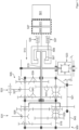
- the dual-clutch transmission 505 includes the first clutch 507, the second clutch 509, an input shaft 515, countershafts 517, 519, and an output shaft 521.
- Other components such as the transmission housing 545 and gear pairs 539, 541, 543 also belong to the dual-clutch transmission 505.
- the shift sleeves 525, 527, 529 are part of the dual-clutch transmission 505.
- the hydraulic circuit 1 Another part of the hydraulic circuit 1 is a control 5 for selecting sleeves.
- the (in Figure 2 not shown) sleeves are gear engagement elements of a gear change transmission (cf. Figure 1 ).
- the hydraulic circuit 1 has a control valve 157 which receives its control pressure from a central pressure line 15 (similar to the control elements of the other hydraulic branches 65, 65 I , 65", 65 III , 65 IV , 65 V ).
- a further subgroup can be, for example, a hydraulic actuating mechanism of a motor vehicle component, such as for a trunk lid or for a chassis leveling system.
- the first drain line 133 is a line that supplies an oil distribution device for lubricating transmission components. This allows transmission components such as gear pairs 539, 541, 543 (see Figure 1 ) are moistened with hydraulic fluid 109 for lubrication.
- All of these subcircuits and assemblies branch off from the central pressure line 15 in a branch line fashion.
- the central pressure line 15 is routed through the entire hydraulic circuit 1 as a central supply line.
- a pump group 19 supplies the central pressure line 15 with hydraulic fluid or hydraulic medium 109.
- the pump group 19 consists of a first pump 21 and a second pump 23.
- the first pump 21 is a combustion engine-driven pump.
- the second pump 23 is an electric motor-driven pump, which can also be referred to as an electric pump. Both pumps 21 and 23 are adjustable pumps, so that pressures and/or delivery volumes can be varied.
- Control level 27 can be used to adjust those actuators 29, 31, 41, and 43 that have control elements such as a flow control valve 81 II , 8 III in their branch.
- Actuators such as the seventh actuator 41 and the eighth actuator 43 can assume multiple positions, e.g., three selected positions to switch a sleeve between three positions such as "left,”"neutral,” and "right.”
- the actuators 29, 31, 33, 35, 37, 39, 41, 43 serve to move actuators, such as an actuator 55 for the movement of a shift sleeve.
- actuators 55 are, for example, a first clutch actuator 57 and a second clutch actuator 59.
- Tappets for example, can be used as actuators. Due to the pressure control valves 51, 53 in the control level 27, the clutch actuator 57, 59 can be moved to a selected position, such as the "closed” or “open” position. Due to the pressure control, any intermediate positions can be assumed by the clutch actuator 57, 59.
- the first actuator 29 and the second actuator 31 are spring-loaded differential cylinders, so that the clutch actuators 57, 59 are held in a preferred position, the "normally open” position. If no active pressure is applied, the connected clutches (cf. Figure 1 ) is held in the open position.
- the first clutch actuator 57 and the second clutch actuator 59 are guided to clutches of a dual clutch group.
- the third clutch actuator 61, 61 I controls a separating clutch of a hybrid powertrain (see Figure 1 ).
- the fourth clutch actuator 63, 63 I controls a controllable differential gear.
- the hydraulic line, hydraulic branch 65 which is also designed with vibration damping, has a control valve 155.
- the clutch actuators 57, 59, 61, 61 I , 63, 63 I are designed as linear cylinders.
- the hydraulic medium 109 is - in the case of normal operation - under such a pressure that the individual hydraulic branches 65, 65 I , 65", 65 III , 65 IV , 65 V , 65 VI , 65 VII can always be sufficiently supplied with hydraulic medium. However, if switching changes occur frequently, it may be that the hydraulic medium 109 needs to be prioritized.
- the central pressure line 15 offers the highest pressure level, especially beyond the pump group 19.
- the shut-off valve 103 generates (only) a pressure drop in the mbar range.
- the pressure is significantly influenced by the pressure control valves 51, 53.
- the position of the first actuator 29 and the second actuator 31 is adjusted depending on the pressure downstream of the pressure control valves 51, 53.
- the pressure control can enable cross-fading from one clutch to the other.
- shut-off valve 103 moves into a discharge position 107 for the hydraulic fluid or hydraulic medium 109, the situation may arise in which the pressure level downstream of the pressure control valves 51, 53 is higher than upstream of the pressure control valves 51, 53 (viewed in relation to the working direction). In such a situation, the bypass lines 67, 68 become effective.
- the hydraulic medium 109 can flow out of the actuator 29, 31.
- the shut-off valves 71, 73 in the bypass lines 67, 68 are arranged antiparallel to the pressure control valves 51, 53.
- the pressure control valve 53 is a three-state valve.
- One of the switching states of the pressure control valve 53 is a blocking state 79.
- the pressure control valve 53 In this position of a piston (see also a piston 97 of the pressure control valve 51) of the pressure control valve 53, the pressure control valve 53 has assumed a blocking state 79.
- the supply line 85 is controlled only via a check valve 83.
- pressure reduction in the supply line 85 can occur via the rotary feedthroughs of the clutch actuator 59 and via the check valve 83.
- the check valve 83 ensures a faster pressure reduction towards the supply side 101. Due to a pressure difference, the check valve 83 moves in a flow direction opposite to the usual flow direction 89.
- the first pressure control valve 51 is an electromagnetically controlled three-position pressure control valve.
- the pressure control valve 51 is a 3/3 spring-loaded Solenoid valve 91.
- the 3/3-way solenoid valve 91 offers a first position, a second position, and a third position.
- One of the positions of the 3/3-way solenoid valve 91 is a flow position 115.
- One of the positions of the solenoid valve 91 is a drain position 111.
- the 3/3-way pressure control valve 91 has a center position 113.
- the valve assumes one of the positions such as the drain position 111, the center position 113, or the flow position 115.
- the solenoid can be used to move the piston 97 of the 3/3-way pressure control valve 91.
- the 3/3-way solenoid valve 91 has a feedback 95, which is a hydraulic feedback.
- the 3/3 pressure control valve 91 has a spring 121, which can also move the piston 97.
- the shut-off valve 103 has a sump return line 119.
- the hydraulic circuit 1 has flow control valves 81, 81 I , 81 II , 81 III in three hydraulic branches 65 I , 65 III , 65 V.
- hydraulic medium 109 can be discharged into or from the corresponding hydraulic branch 65 via the sump return line 117, 119.
- Faster outflow is ensured by the check valves 71, 73, particularly as bypass paths (bypass lines 67, 68) around the pressure control valves 51, 53.
- the check valves 71, 73 are implemented as check valves. A brief separation of the clutches is possible using the spring-loaded clutch actuators 57, 59.
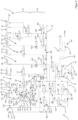
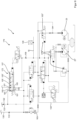
- the hydraulic circuit 1 is a hydraulic circuit integrated in a control plate 167, which has the larger-volume components and assemblies as well as those components that are to be placed elsewhere beyond the control plate 167, i.e., outside an edge 169 of the control plate 167.
- Actuators such as a first actuator 29, a second actuator 31, or a third actuator 33, are to be arranged as actuators, such as the actuator 55, directly on the element to be controlled, like a clutch.
- Pumps 21, 23 of a pump group 19 must be a hydraulic fluid reservoir such as a tank 149, so that the pumps 21, 23 are arranged outside the control plate 167 directly in the area of the tank 149.
- the control plate 167 has, e.g. B.
- control plate 167 in the area of the control plate edge 169, connecting elements (shown as examples are the connecting elements 173, 173 I , 173", 173 III , 173 IV , 173 V ) for lines or for the hydraulic plate (control plate 167). It is understandable to a person skilled in the art that the part of the circuit diagram summarized as control plate 167 can also be divided between several control plates, e.g. if the spatial conditions of the housing 545 of the transmission such as the dual clutch transmission 505 or weight requirements or weight distribution of the transmission make it necessary.
- valves such as the check valve 103 of a first hydraulic branch 65 in the control plate can be implemented as a two-part valve, of which a first valve is a pilot control valve 171 and the second valve, referred to as the main control valve 172, offers the switching positions such as flow positions 105, 105I , 105" and at least one drain position 107.
- the second valve, the main control valve 172 or the second part of the check valve 103 is the actual control valve, with the control being hydraulically controlled via the pilot control valve 171.
- a control line 177 is formed between the pilot control valve 171 and the actual control piston.
- the hydraulically actuated main piston of the valve 172 is actuated via the control line 177.
- the hydraulic branches 65, 65 I , 65", 65 III , 65 IV , 65 V , 65 VI , 65 VII lead away from the central pressure line 15.
- a priority hydraulic circuit valve 159 which is controlled via the pilot control valve 171 I , is there to give selected hydraulic branches, such as the first hydraulic branch 65 for clutch control and clutch cooling, priority over less important hydraulic circuits such as the control 7 for body components.
- the priority hydraulic circuit valve 159 is a hydraulic pressure compensator valve with three switching states. It only switches the return line 151 when there is sufficient pressure and is controlled by the pilot control valve 171 I. In a switching state that is more likely to be assumed, the drain line 135, which is responsible for cooling the clutches, is released.
- a further stabilization measure which can be seen from the circuit diagram, is the installation of orifices 170, 170 I in the control lines between the pilot valves 171, 171 I and the respective controlling valve 172, 159.
- an orifice 170, 170 I is installed in lines such as the control lines that come from the pilot valves 171, 171 I to suppress vibrations.
- cooling of the hydraulic fluid 109 via the cooler 163 can be dispensed with during short periods, lasting only a few seconds, for example. It is also possible not to supply the drain line 133, 135 I , which is designed to provide coolant or lubricant, e.g., for lubricating wheel sets, with additional hydraulic fluid 109 in certain phases. It is therefore advantageous to connect the cooler 163 downstream of the priority circuit 179 I , 179" or 179 III and to connect the drain line 133 or 135 I to the cooler 163 on the downstream side.
- Whether sufficient pressure prevails in the central pressure line 15 can be monitored with a pressure sensor 129. If the pressure in the central pressure line 15 exceeds a maximum value, the hydraulically clamped priority hydraulic circuit valve 159 can automatically discharge hydraulic fluid 109 via the return line 151 due to its pressure compensator design.
- the hydraulic fluid 109 can be made available to the pumps 21 I , 23 on the intake side. The hydraulic volume not required by the pumps 21 I , 23 flows into the tank 149.
- the hydraulic circuit 1 I (after Figure 3 ) has return lines towards the sump 149 at more than ten locations, with some of the return lines being filled if there is too much hydraulic fluid 109.
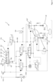
- shut-off valve 103 (see Figures 2 to 6 ), which is located in front of the pressure control valves 51, 53, for supplying the first and second actuators 29, 31, while a coolant flow 110 is either only throttled or even completely blocked off by the shut-off valve 103.
- the main control valve 172 has, as in Figure 3 drawn, four ports 181, 183, 185, 187. From Figure 4 It can be seen that there is another port, the tank connection 189.
- the pilot valve 171 determines the position or switching state of the main control valve 172. In the switching position, which is the through position 105, only a throttled flow of the hydraulic fluid 109 reaches the third drain line 135 when it leaves the port 183. Via the first working port 181, hydraulic fluid 109 reaches the pressure control valves 51, 53 at the pressure level of the central pressure line 15.
- the pressure prevailing in a supply line to the first and second actuators 29, 31 can be monitored or measured by means of pressure sensors 125, 127.
- the strength of the coolant flow 110 I can be influenced by two black-white valves connected in antiparallel.
- an interaction of three Valves for each of the flows or hydraulic fluid flows Q 1 , Q 2 , 110 I can be adjusted as required and in accordance with the supply by the pumps 21, 21 I , 23. If the pumps 21, 21 I , 23 deliver too much pressure or too large a hydraulic fluid flow into the central pressure line 15, the portion that is not required or that is excessive can be diverted back to tank 149 or in the direction of tank 149 via the return line or recirculation line 151.
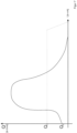
- Figure 7 illustrates a flow characteristic curve downstream of valve 172.
- Pressure compensator valve 139 Section especially the hydraulic circuit 141 first supply line 143 second supply line 145 workspace 147 Linear cylinder 149 tank 151 Return line 153 filter 155, 155', 155" Control valve, especially for differential control 157 Control valve, especially for controlling aerodynamic components 159
- Priority hydraulic circuit valve 163 cooler 167 control plate 169 Control plate edge 170, 170 I aperture 171, 171 I pilot valve 172 Main control valve 173, 173 I , 173", 173 III , 173 IV , 173 V Connecting element for lines and/or hydraulic plate, e.g.
Landscapes
- Engineering & Computer Science (AREA)
- General Engineering & Computer Science (AREA)
- Mechanical Engineering (AREA)
- Hydraulic Clutches, Magnetic Clutches, Fluid Clutches, And Fluid Joints (AREA)
- Control Of Transmission Device (AREA)
Claims (10)
- Procédé pour la commande de transmission avec un circuit hydraulique (1) par lequel des organes de réglage (29, 31, 33, 35, 37, 39, 41, 43, 45) du circuit hydraulique (1) qui opèrent avec des pressions de travail sont commandés pour l'actionnement de composants de transmission comme des embrayages (507, 509, 511), en particulier des doubles embrayages (507, 509) ou des tronçons d'entraînement (500) avec plus de deux embrayages à friction, et par lequel un moyen hydraulique (109) pour un refroidissement (135) et/ou une lubrification (133) de composants de transmission individuels (539, 541, 543) est distribué, avec un circuit prioritaire (179, 179', 179", 179"', 159) dans le circuit hydraulique par lequel une priorisation de flux hydrauliques (Q) est effectuée en fonction d'une position de commutation (105, 105', 105", 107) d'au moins une soupape, caractérisé en ce quele circuit prioritaire (179, 179', 179", 179"', 159) commande, par des positions de piston d'une seule soupape (103) équipée en tant que soupape à tiroir de piston (172) avec au moins deux ports de travail (181, 183) et avec au moins deux ports d'alimentation en pression (185, 187), une pression de travail sur un ensemble (3) du circuit hydraulique (1) ainsi qu'un flux (Q) d'un moyen hydraulique (109) via la soupape (103) avec un niveau de pression qui diffère de la pression de travail, par exemple d'un courant de moyen de refroidissement (110, 110') avec une pression plus faible,dans lequel la soupape (103) est une première soupape directionnelle prioritaire (171, 172) qui est commandée activement de telle sorte qu'une fermeture successive de ses ports de travail (181, 183) ait lieu,cependant qu'un port de travail (181) prévu pour un actionnement d'embrayages (507, 509, 511) est le port de travail (181) fermé en dernier.
- Procédé pour la commande de transmission selon la revendication 1, caractérisé en ce que la soupape à tiroir de piston (172) est une soupape à tiroir de piston (172) à commande pilote (171) et/ou une soupape à cartouche 4/4 ou une soupape à cartouche 5/4.
- Procédé pour la commande de transmission selon l'une des revendications précédentes, caractérisé en ce que l'ensemble est un ensemble d'embrayages (3) pouvant être actionné hydrauliquement qui peut, avec au moins deux pistons linéaires (147), en particulier précontraints unilatéralement par un ressort, mettre en œuvre un changement de position de moyens d'embrayage (507, 509, 511) comme des garnitures de friction d'un embrayage normalement ouvert.
- Procédé pour la commande de transmission selon l'une des revendications précédentes, caractérisé en ce que, dans une position de repos (105) de la soupape unique (103), un premier flux de moyen hydraulique est dirigé sur l'ensemble et que simultanément un second flux de moyen hydraulique est mis à disposition comme moyen hydraulique pour le refroidissement et/ou la lubrification du circuit prioritaire (179, 179', 179", 179"', 159).
- Procédé pour la commande de transmission selon l'une des revendications précédentes, caractérisé en ce que la soupape unique (103), en particulier sous forme d'une soupape directionnelle prioritaire (171, 172), est sur le plan fonctionnel une soupape d'arrêt (103) qui doit être mise activement dans un état de blocage (107).
- Procédé pour la commande de transmission selon l'une des revendications précédentes, caractérisé en ce que la soupape unique (103) comprend au moins quatre états (105, 105', 105", 107) dont trois états (105, 105', 105") laissent passer un flux de moyen hydraulique dans au moins une de deux conduites de consommation.
- Procédé pour la commande de transmission selon l'une des revendications précédentes, caractérisé en ce que la soupape unique (103) est conçue pour une pression de travail qui se situe au moins quelques bars au-dessus du niveau de pression qui diffère.
- Procédé pour la commande de transmission selon l'une des revendications précédentes 2 à 7, caractérisé en ce que la soupape unique présente, en position de repos du piston, des passages vers les deux ports de travail (181, 183), cependant que suit, dans une première position actionnée qui suit la position de repos (105'), un second état de passage vers les deux ports de travail (181, 183) et cependant que, dans une seconde position actionnée (105") dans laquelle il existe une commande d'un niveau énergétique plus élevé de la seule soupape, qui est par exemple donnée par un rapport cyclique actif plus long, il n'existe plus qu'un passage vers l'un des deux ports de travail (181).
- Procédé pour la commande de transmission selon l'une des revendications précédentes 2 à 8, caractérisé en ce que, dans une position de blocage (107), il y a commutation d'un délestage hydraulique de l'un des ports de travail (181) par rapport à un réservoir (149) tandis que l'autre port de travail (183) est découplé hydrauliquement d'un côté alimentation.
- Procédé pour la commande de transmission selon la revendication 9, caractérisé en ce qu'il est prévu, dans la position de blocage (107) de la soupape directionnelle prioritaire, une décharge rapide (67, 68) par rapport au réservoir (149) par la soupape directionnelle prioritaire (172) tandis qu'il reste du moyen hydraulique (109) découplé et bloqué dans au moins une conduite (135) qui est raccordée à l'autre port de travail (183).
Applications Claiming Priority (2)
| Application Number | Priority Date | Filing Date | Title |
|---|---|---|---|
| DE202016105346 | 2016-09-26 | ||
| PCT/EP2017/074334 WO2018055192A1 (fr) | 2016-09-26 | 2017-09-26 | Système hydraulique d'alimentation, entre autres pour actionneurs d'embrayage |
Publications (3)
| Publication Number | Publication Date |
|---|---|
| EP3516272A1 EP3516272A1 (fr) | 2019-07-31 |
| EP3516272B1 EP3516272B1 (fr) | 2021-12-01 |
| EP3516272B2 true EP3516272B2 (fr) | 2025-04-16 |
Family
ID=59969160
Family Applications (2)
| Application Number | Title | Priority Date | Filing Date |
|---|---|---|---|
| EP17772699.9A Active EP3516272B2 (fr) | 2016-09-26 | 2017-09-26 | Méthode de contrôle de transmission avec un circuit hydraulique |
| EP17780052.1A Active EP3516269B1 (fr) | 2016-09-26 | 2017-09-26 | Circuit hydraulique d'une transmission à embrayage double, en particulier comprenant une commande d'embrayage, et procédé de réaction d'urgence |
Family Applications After (1)
| Application Number | Title | Priority Date | Filing Date |
|---|---|---|---|
| EP17780052.1A Active EP3516269B1 (fr) | 2016-09-26 | 2017-09-26 | Circuit hydraulique d'une transmission à embrayage double, en particulier comprenant une commande d'embrayage, et procédé de réaction d'urgence |
Country Status (2)
| Country | Link |
|---|---|
| EP (2) | EP3516272B2 (fr) |
| WO (2) | WO2018055192A1 (fr) |
Families Citing this family (2)
| Publication number | Priority date | Publication date | Assignee | Title |
|---|---|---|---|---|
| DE102020004981B3 (de) | 2020-07-15 | 2021-07-08 | Daimler Ag | Automatikgetriebe für ein Kraftfahrzeug, Verfahren zum Betreiben eines solchen Automatikgetriebes sowie Kraftfahrzeug mit einem solchen Automatikgetriebe |
| DE102021202815A1 (de) | 2021-03-23 | 2022-09-29 | Zf Friedrichshafen Ag | Hydrauliksystem für ein Doppelkupplungsgetriebe |
Citations (2)
| Publication number | Priority date | Publication date | Assignee | Title |
|---|---|---|---|---|
| DE4004854A1 (de) † | 1990-02-16 | 1991-08-22 | Bosch Gmbh Robert | Hydraulische steuereinrichtung |
| US20130037144A1 (en) † | 2010-02-24 | 2013-02-14 | Torotrak (Development) Limited | Fluid supply for continuously variable transmission |
Family Cites Families (33)
| Publication number | Priority date | Publication date | Assignee | Title |
|---|---|---|---|---|
| DE1004386B (de) | 1953-05-23 | 1957-03-14 | Genevoise Instr Physique | Verfahren zur Kontrolle des Abstandes eines beweglichen Koerpers von einer Geraden und Einrichtung zu dessen Durchfuehrung |
| JPS5697629A (en) | 1980-01-08 | 1981-08-06 | Yamaha Motor Co Ltd | Oil pressure controller for hydraulic multiple-disc clutch |
| JPS5854259A (ja) | 1981-09-25 | 1983-03-31 | Toyo Umpanki Co Ltd | パワ−シフトトランスミツシヨンの制御弁 |
| DE3241751C2 (de) | 1982-11-11 | 1985-10-03 | Danfoss A/S, Nordborg | Prioritätsventil für hydraulische Anlagen |
| DE3420060A1 (de) | 1983-05-31 | 1984-12-06 | Kabushiki Kaisha Komatsu Seisakusho, Tokio/Tokyo | Fluidbetriebene getriebesteuerung |
| US5020324A (en) | 1990-03-13 | 1991-06-04 | Deere & Company | Charge flow priority circuit |
| US5315901A (en) | 1992-12-17 | 1994-05-31 | Ford Motor Company | Automatic transmission with a modulated pressure converter bypass clutch priority valve circuit |
| DE10134115B4 (de) | 2001-07-13 | 2014-05-28 | Volkswagen Ag | Doppelkupplungsgetriebe eines Kraftfahrzeuges mit einem Hydraulikkreis und Verfahren zur hydraulischen Steuerung eines Doppelkupplungsgetriebes |
| EP1450076A3 (fr) | 2003-02-21 | 2010-06-09 | Borgwarner, Inc. | Procédé de commande d'une transmission à double embrayages |
| DE10320524A1 (de) | 2003-04-30 | 2004-11-25 | Getrag Getriebe- Und Zahnradfabrik Hermann Hagenmeyer Gmbh & Cie Kg | Hydraulikkreis zur Steuerung eines Antriebsstranges |
| US7431043B2 (en) | 2005-03-17 | 2008-10-07 | Borgwarner Inc. | Automatic transmission having a pressure regulator with flow force compensation |
| DE102005015911A1 (de) | 2005-04-07 | 2006-10-12 | Volkswagen Ag | Hydrauliksystem für ein Kraftfahrzeug |
| EP1717473B1 (fr) | 2005-04-25 | 2009-09-02 | HOERBIGER Antriebstechnik GmbH | Dispositif de contrôle d'actionnement pour les disques d'un embrayage hydraulique double |
| JP4722710B2 (ja) | 2006-01-11 | 2011-07-13 | トヨタ自動車株式会社 | 変速機の油圧制御装置 |
| JP3995018B2 (ja) | 2006-01-31 | 2007-10-24 | トヨタ自動車株式会社 | ハイブリッド車両の制御装置 |
| DE102006016397B4 (de) | 2006-04-07 | 2014-08-07 | Hofer Mechatronik Gmbh | Getriebe und ein Verfahren zur Steuerung eines Getriebes für ein Kraftfahrzeug |
| GB0700974D0 (en) | 2007-01-18 | 2007-02-28 | Ricardo Uk Ltd | Hydraulic priority to clutch control |
| DE102007023072B4 (de) | 2007-05-16 | 2017-02-23 | Volkswagen Ag | Hydraulische Steuerungseinrichtung für ein Getriebe |
| DE102009005753A1 (de) * | 2009-01-23 | 2010-07-29 | Daimler Ag | Hydraulische Steuerung für ein automatisiertes Getriebe |
| DE102010032657A1 (de) | 2009-08-06 | 2011-02-10 | Schaeffler Technologies Gmbh & Co. Kg | Hydrauliksystem Steuerung |
| DE102010037243B4 (de) | 2010-08-31 | 2016-11-17 | Hofer Mechatronik Gmbh | Hydraulische Steuerung eines Doppelkupplungsgetriebes und Verfahren zum Betrieb zweier als Aktuatoren ausgebildeter Kupplungen |
| DE102010036545B4 (de) | 2010-07-21 | 2015-01-08 | Hofer Mechatronik Gmbh | Getriebehydraulik eines Getriebes mit mehreren Kupplungen und Steuerungsverfahren mit hydraulischen Ventilen für mehrere Kupplungen umfassende Getriebe, die eine erhöhte Betriebssicherheit bieten |
| EP2557336B1 (fr) | 2010-07-21 | 2018-11-07 | hofer mechatronik GmbH | Commande hydraulique pour boîte de vitesses à double embrayage et son procédé de contrôle |
| DE102011100857A1 (de) | 2011-05-06 | 2012-11-08 | Audi Ag | Doppelkupplungsgetriebe |
| DE102011100849A1 (de) | 2011-05-06 | 2012-11-08 | Audi Ag | Doppelkupplungsgetriebe |
| DE102011100799B4 (de) | 2011-05-06 | 2017-06-01 | Audi Ag | Doppelkupplungsgetriebe, Verfahren zum Betreiben |
| DE102011100862B4 (de) * | 2011-05-06 | 2022-12-15 | Audi Ag | Doppelkupplungsgetriebe |
| DE102013224244A1 (de) | 2012-12-20 | 2014-06-26 | Volkswagen Aktiengesellschaft | Hydraulikkreislauf |
| DE102013008740B4 (de) * | 2013-05-23 | 2018-05-24 | Audi Ag | Hydrauliksystem für ein Doppelkupplungsgetriebe eines Kraftfahrzeugs |
| KR101491267B1 (ko) | 2013-06-26 | 2015-02-11 | 현대 파워텍 주식회사 | 더블 클러치 변속기용 유압 제어 장치 |
| DE102013219386B4 (de) * | 2013-09-26 | 2026-01-29 | Volkswagen Aktiengesellschaft | Hydraulische Steuerungsvorrichtung eines Doppelkupplungsgetriebes |
| US9512919B2 (en) | 2015-03-24 | 2016-12-06 | Ford Global Technologies, Llc | Transmission hydraulic control system |
| US9951861B2 (en) | 2015-03-24 | 2018-04-24 | Ford Global Technologies, Llc | Transmission hydraulic control system |
-
2017
- 2017-09-26 WO PCT/EP2017/074334 patent/WO2018055192A1/fr not_active Ceased
- 2017-09-26 WO PCT/EP2017/074382 patent/WO2018055204A1/fr not_active Ceased
- 2017-09-26 EP EP17772699.9A patent/EP3516272B2/fr active Active
- 2017-09-26 EP EP17780052.1A patent/EP3516269B1/fr active Active
Patent Citations (2)
| Publication number | Priority date | Publication date | Assignee | Title |
|---|---|---|---|---|
| DE4004854A1 (de) † | 1990-02-16 | 1991-08-22 | Bosch Gmbh Robert | Hydraulische steuereinrichtung |
| US20130037144A1 (en) † | 2010-02-24 | 2013-02-14 | Torotrak (Development) Limited | Fluid supply for continuously variable transmission |
Also Published As
| Publication number | Publication date |
|---|---|
| EP3516272B1 (fr) | 2021-12-01 |
| EP3516269A1 (fr) | 2019-07-31 |
| EP3516272A1 (fr) | 2019-07-31 |
| EP3516269B1 (fr) | 2022-09-21 |
| WO2018055204A1 (fr) | 2018-03-29 |
| WO2018055192A1 (fr) | 2018-03-29 |
Similar Documents
| Publication | Publication Date | Title |
|---|---|---|
| EP2382402B1 (fr) | Contrôle hydraulique pour une transmission automatique | |
| EP3396213B1 (fr) | Procédé de fonctionnement d'une transmission hydraulique à une commande hydraulique | |
| EP3134664B1 (fr) | Dispositif de transmission à système hydraulique | |
| EP3468826B1 (fr) | Système hydraulique d'actionnement d'un embrayage muni d'une lubrification à la demande de l'embrayage | |
| DE102010036545B4 (de) | Getriebehydraulik eines Getriebes mit mehreren Kupplungen und Steuerungsverfahren mit hydraulischen Ventilen für mehrere Kupplungen umfassende Getriebe, die eine erhöhte Betriebssicherheit bieten | |
| EP3516273B1 (fr) | Traitement de fluide hydraulique à alimentation en huile par système de pompe double | |
| EP3134662B1 (fr) | Système hydraulique d'une transmission comprenant plusieurs soupapes de régulation de pression | |
| DE102009005755A1 (de) | Steuerungseinrichtung für ein automatisiertes Zahnräderwechselgetriebe | |
| DE19909690C2 (de) | Verfahren zur Steuerung zur Befüllung eines hydrodynamischen Bauelementes und Steuervorrichtung | |
| DE102014214441B4 (de) | Verfahren und Anordnung zum Verzögern eines Hydrostatischen Antriebs | |
| DE102011100862B4 (de) | Doppelkupplungsgetriebe | |
| WO2007068319A1 (fr) | Systeme hydraulique sur vehicules automobiles | |
| DE102014207798A1 (de) | Verfahren zum Betreiben einer hydraulischen Betätigungsvorrichtung für ein Getriebe mit zwei Hydraulikpumpen | |
| EP3516272B2 (fr) | Méthode de contrôle de transmission avec un circuit hydraulique | |
| DE102009038377A1 (de) | Hydraulikanordnung | |
| DE102006049973A1 (de) | Hydraulische Steuerungsvorrichtung eines automatisierten Doppelkupplungsgestriebes | |
| DE102020205759B3 (de) | Hydraulikkreis für ein Doppelkupplungsgetriebe sowie ein Verfahren zum Betreiben des Hydraulikkreises | |
| DE102014207806B4 (de) | Hydraulische Betätigungsvorrichtung für ein Getriebe | |
| DE102012014784A1 (de) | Hydrauliksystem für ein Kraftfahrzeugautomatikgetriebe | |
| DE102009005754B4 (de) | Hydraulische Steuerung für ein automatisiertes Zahnräderwechselgetriebe eines Kraftfahrzeugs | |
| DE102022206502A1 (de) | Verfahren zur Steuerung eines Pumpensystems | |
| DE102014207803A1 (de) | Hydraulische Betätigungsvorrichtung mit einem Gehäuse für ein Getriebe mit zwei Hydraulikpumpen |
Legal Events
| Date | Code | Title | Description |
|---|---|---|---|
| STAA | Information on the status of an ep patent application or granted ep patent |
Free format text: STATUS: UNKNOWN |
|
| STAA | Information on the status of an ep patent application or granted ep patent |
Free format text: STATUS: THE INTERNATIONAL PUBLICATION HAS BEEN MADE |
|
| PUAI | Public reference made under article 153(3) epc to a published international application that has entered the european phase |
Free format text: ORIGINAL CODE: 0009012 |
|
| STAA | Information on the status of an ep patent application or granted ep patent |
Free format text: STATUS: REQUEST FOR EXAMINATION WAS MADE |
|
| 17P | Request for examination filed |
Effective date: 20190325 |
|
| AK | Designated contracting states |
Kind code of ref document: A1 Designated state(s): AL AT BE BG CH CY CZ DE DK EE ES FI FR GB GR HR HU IE IS IT LI LT LU LV MC MK MT NL NO PL PT RO RS SE SI SK SM TR |
|
| AX | Request for extension of the european patent |
Extension state: BA ME |
|
| RIN1 | Information on inventor provided before grant (corrected) |
Inventor name: KEHRER, MARCUS Inventor name: EBINGER, GUENTER Inventor name: WILD, ANDREAS Inventor name: UNRUH, SWEN |
|
| DAV | Request for validation of the european patent (deleted) | ||
| DAX | Request for extension of the european patent (deleted) | ||
| GRAP | Despatch of communication of intention to grant a patent |
Free format text: ORIGINAL CODE: EPIDOSNIGR1 |
|
| STAA | Information on the status of an ep patent application or granted ep patent |
Free format text: STATUS: GRANT OF PATENT IS INTENDED |
|
| INTG | Intention to grant announced |
Effective date: 20210430 |
|
| GRAS | Grant fee paid |
Free format text: ORIGINAL CODE: EPIDOSNIGR3 |
|
| GRAJ | Information related to disapproval of communication of intention to grant by the applicant or resumption of examination proceedings by the epo deleted |
Free format text: ORIGINAL CODE: EPIDOSDIGR1 |
|
| GRAL | Information related to payment of fee for publishing/printing deleted |
Free format text: ORIGINAL CODE: EPIDOSDIGR3 |
|
| STAA | Information on the status of an ep patent application or granted ep patent |
Free format text: STATUS: REQUEST FOR EXAMINATION WAS MADE |
|
| GRAP | Despatch of communication of intention to grant a patent |
Free format text: ORIGINAL CODE: EPIDOSNIGR1 |
|
| STAA | Information on the status of an ep patent application or granted ep patent |
Free format text: STATUS: GRANT OF PATENT IS INTENDED |
|
| INTC | Intention to grant announced (deleted) | ||
| RAP1 | Party data changed (applicant data changed or rights of an application transferred) |
Owner name: HOFER POWERTRAIN INNOVATION GMBH |
|
| GRAA | (expected) grant |
Free format text: ORIGINAL CODE: 0009210 |
|
| STAA | Information on the status of an ep patent application or granted ep patent |
Free format text: STATUS: THE PATENT HAS BEEN GRANTED |
|
| INTG | Intention to grant announced |
Effective date: 20211021 |
|
| AK | Designated contracting states |
Kind code of ref document: B1 Designated state(s): AL AT BE BG CH CY CZ DE DK EE ES FI FR GB GR HR HU IE IS IT LI LT LU LV MC MK MT NL NO PL PT RO RS SE SI SK SM TR |
|
| REG | Reference to a national code |
Ref country code: GB Ref legal event code: FG4D Free format text: NOT ENGLISH |
|
| REG | Reference to a national code |
Ref country code: AT Ref legal event code: REF Ref document number: 1452058 Country of ref document: AT Kind code of ref document: T Effective date: 20211215 Ref country code: CH Ref legal event code: EP |
|
| REG | Reference to a national code |
Ref country code: IE Ref legal event code: FG4D Free format text: LANGUAGE OF EP DOCUMENT: GERMAN |
|
| REG | Reference to a national code |
Ref country code: DE Ref legal event code: R096 Ref document number: 502017012154 Country of ref document: DE |
|
| REG | Reference to a national code |
Ref country code: LT Ref legal event code: MG9D |
|
| REG | Reference to a national code |
Ref country code: NL Ref legal event code: MP Effective date: 20211201 |
|
| PG25 | Lapsed in a contracting state [announced via postgrant information from national office to epo] |
Ref country code: RS Free format text: LAPSE BECAUSE OF FAILURE TO SUBMIT A TRANSLATION OF THE DESCRIPTION OR TO PAY THE FEE WITHIN THE PRESCRIBED TIME-LIMIT Effective date: 20211201 Ref country code: LT Free format text: LAPSE BECAUSE OF FAILURE TO SUBMIT A TRANSLATION OF THE DESCRIPTION OR TO PAY THE FEE WITHIN THE PRESCRIBED TIME-LIMIT Effective date: 20211201 Ref country code: FI Free format text: LAPSE BECAUSE OF FAILURE TO SUBMIT A TRANSLATION OF THE DESCRIPTION OR TO PAY THE FEE WITHIN THE PRESCRIBED TIME-LIMIT Effective date: 20211201 Ref country code: BG Free format text: LAPSE BECAUSE OF FAILURE TO SUBMIT A TRANSLATION OF THE DESCRIPTION OR TO PAY THE FEE WITHIN THE PRESCRIBED TIME-LIMIT Effective date: 20220301 |
|
| PG25 | Lapsed in a contracting state [announced via postgrant information from national office to epo] |
Ref country code: SE Free format text: LAPSE BECAUSE OF FAILURE TO SUBMIT A TRANSLATION OF THE DESCRIPTION OR TO PAY THE FEE WITHIN THE PRESCRIBED TIME-LIMIT Effective date: 20211201 Ref country code: PL Free format text: LAPSE BECAUSE OF FAILURE TO SUBMIT A TRANSLATION OF THE DESCRIPTION OR TO PAY THE FEE WITHIN THE PRESCRIBED TIME-LIMIT Effective date: 20211201 Ref country code: NO Free format text: LAPSE BECAUSE OF FAILURE TO SUBMIT A TRANSLATION OF THE DESCRIPTION OR TO PAY THE FEE WITHIN THE PRESCRIBED TIME-LIMIT Effective date: 20220301 Ref country code: LV Free format text: LAPSE BECAUSE OF FAILURE TO SUBMIT A TRANSLATION OF THE DESCRIPTION OR TO PAY THE FEE WITHIN THE PRESCRIBED TIME-LIMIT Effective date: 20211201 Ref country code: HR Free format text: LAPSE BECAUSE OF FAILURE TO SUBMIT A TRANSLATION OF THE DESCRIPTION OR TO PAY THE FEE WITHIN THE PRESCRIBED TIME-LIMIT Effective date: 20211201 Ref country code: GR Free format text: LAPSE BECAUSE OF FAILURE TO SUBMIT A TRANSLATION OF THE DESCRIPTION OR TO PAY THE FEE WITHIN THE PRESCRIBED TIME-LIMIT Effective date: 20220302 Ref country code: ES Free format text: LAPSE BECAUSE OF FAILURE TO SUBMIT A TRANSLATION OF THE DESCRIPTION OR TO PAY THE FEE WITHIN THE PRESCRIBED TIME-LIMIT Effective date: 20211201 |
|
| PG25 | Lapsed in a contracting state [announced via postgrant information from national office to epo] |
Ref country code: NL Free format text: LAPSE BECAUSE OF FAILURE TO SUBMIT A TRANSLATION OF THE DESCRIPTION OR TO PAY THE FEE WITHIN THE PRESCRIBED TIME-LIMIT Effective date: 20211201 |
|
| PG25 | Lapsed in a contracting state [announced via postgrant information from national office to epo] |
Ref country code: SM Free format text: LAPSE BECAUSE OF FAILURE TO SUBMIT A TRANSLATION OF THE DESCRIPTION OR TO PAY THE FEE WITHIN THE PRESCRIBED TIME-LIMIT Effective date: 20211201 Ref country code: SK Free format text: LAPSE BECAUSE OF FAILURE TO SUBMIT A TRANSLATION OF THE DESCRIPTION OR TO PAY THE FEE WITHIN THE PRESCRIBED TIME-LIMIT Effective date: 20211201 Ref country code: RO Free format text: LAPSE BECAUSE OF FAILURE TO SUBMIT A TRANSLATION OF THE DESCRIPTION OR TO PAY THE FEE WITHIN THE PRESCRIBED TIME-LIMIT Effective date: 20211201 Ref country code: PT Free format text: LAPSE BECAUSE OF FAILURE TO SUBMIT A TRANSLATION OF THE DESCRIPTION OR TO PAY THE FEE WITHIN THE PRESCRIBED TIME-LIMIT Effective date: 20220401 Ref country code: EE Free format text: LAPSE BECAUSE OF FAILURE TO SUBMIT A TRANSLATION OF THE DESCRIPTION OR TO PAY THE FEE WITHIN THE PRESCRIBED TIME-LIMIT Effective date: 20211201 Ref country code: CZ Free format text: LAPSE BECAUSE OF FAILURE TO SUBMIT A TRANSLATION OF THE DESCRIPTION OR TO PAY THE FEE WITHIN THE PRESCRIBED TIME-LIMIT Effective date: 20211201 |
|
| REG | Reference to a national code |
Ref country code: DE Ref legal event code: R026 Ref document number: 502017012154 Country of ref document: DE |
|
| PLBI | Opposition filed |
Free format text: ORIGINAL CODE: 0009260 |
|
| PLAX | Notice of opposition and request to file observation + time limit sent |
Free format text: ORIGINAL CODE: EPIDOSNOBS2 |
|
| PG25 | Lapsed in a contracting state [announced via postgrant information from national office to epo] |
Ref country code: IS Free format text: LAPSE BECAUSE OF FAILURE TO SUBMIT A TRANSLATION OF THE DESCRIPTION OR TO PAY THE FEE WITHIN THE PRESCRIBED TIME-LIMIT Effective date: 20220401 |
|
| 26 | Opposition filed |
Opponent name: ZF FRIEDRICHSHAFEN AG Effective date: 20220826 |
|
| PG25 | Lapsed in a contracting state [announced via postgrant information from national office to epo] |
Ref country code: DK Free format text: LAPSE BECAUSE OF FAILURE TO SUBMIT A TRANSLATION OF THE DESCRIPTION OR TO PAY THE FEE WITHIN THE PRESCRIBED TIME-LIMIT Effective date: 20211201 Ref country code: AL Free format text: LAPSE BECAUSE OF FAILURE TO SUBMIT A TRANSLATION OF THE DESCRIPTION OR TO PAY THE FEE WITHIN THE PRESCRIBED TIME-LIMIT Effective date: 20211201 |
|
| PG25 | Lapsed in a contracting state [announced via postgrant information from national office to epo] |
Ref country code: SI Free format text: LAPSE BECAUSE OF FAILURE TO SUBMIT A TRANSLATION OF THE DESCRIPTION OR TO PAY THE FEE WITHIN THE PRESCRIBED TIME-LIMIT Effective date: 20211201 |
|
| PLBB | Reply of patent proprietor to notice(s) of opposition received |
Free format text: ORIGINAL CODE: EPIDOSNOBS3 |
|
| RAP2 | Party data changed (patent owner data changed or rights of a patent transferred) |
Owner name: HOFER POWERTRAIN INNOVATION GMBH |
|
| REG | Reference to a national code |
Ref country code: DE Ref legal event code: R081 Ref document number: 502017012154 Country of ref document: DE Owner name: HOFER POWERTRAIN INNOVATION GMBH, DE Free format text: FORMER OWNER: HOFER POWERTRAIN INNOVATION GMBH, 85748 GARCHING, DE |
|
| PG25 | Lapsed in a contracting state [announced via postgrant information from national office to epo] |
Ref country code: MC Free format text: LAPSE BECAUSE OF FAILURE TO SUBMIT A TRANSLATION OF THE DESCRIPTION OR TO PAY THE FEE WITHIN THE PRESCRIBED TIME-LIMIT Effective date: 20211201 |
|
| REG | Reference to a national code |
Ref country code: CH Ref legal event code: PL |
|
| REG | Reference to a national code |
Ref country code: BE Ref legal event code: MM Effective date: 20220930 |
|
| PG25 | Lapsed in a contracting state [announced via postgrant information from national office to epo] |
Ref country code: IT Free format text: LAPSE BECAUSE OF FAILURE TO SUBMIT A TRANSLATION OF THE DESCRIPTION OR TO PAY THE FEE WITHIN THE PRESCRIBED TIME-LIMIT Effective date: 20211201 |
|
| PG25 | Lapsed in a contracting state [announced via postgrant information from national office to epo] |
Ref country code: LU Free format text: LAPSE BECAUSE OF NON-PAYMENT OF DUE FEES Effective date: 20220926 |
|
| PG25 | Lapsed in a contracting state [announced via postgrant information from national office to epo] |
Ref country code: LI Free format text: LAPSE BECAUSE OF NON-PAYMENT OF DUE FEES Effective date: 20220930 Ref country code: IE Free format text: LAPSE BECAUSE OF NON-PAYMENT OF DUE FEES Effective date: 20220926 Ref country code: FR Free format text: LAPSE BECAUSE OF NON-PAYMENT OF DUE FEES Effective date: 20220930 Ref country code: CH Free format text: LAPSE BECAUSE OF NON-PAYMENT OF DUE FEES Effective date: 20220930 |
|
| PG25 | Lapsed in a contracting state [announced via postgrant information from national office to epo] |
Ref country code: BE Free format text: LAPSE BECAUSE OF NON-PAYMENT OF DUE FEES Effective date: 20220930 |
|
| REG | Reference to a national code |
Ref country code: AT Ref legal event code: MM01 Ref document number: 1452058 Country of ref document: AT Kind code of ref document: T Effective date: 20220926 |
|
| PG25 | Lapsed in a contracting state [announced via postgrant information from national office to epo] |
Ref country code: AT Free format text: LAPSE BECAUSE OF NON-PAYMENT OF DUE FEES Effective date: 20220926 |
|
| PG25 | Lapsed in a contracting state [announced via postgrant information from national office to epo] |
Ref country code: HU Free format text: LAPSE BECAUSE OF FAILURE TO SUBMIT A TRANSLATION OF THE DESCRIPTION OR TO PAY THE FEE WITHIN THE PRESCRIBED TIME-LIMIT; INVALID AB INITIO Effective date: 20170926 |
|
| PG25 | Lapsed in a contracting state [announced via postgrant information from national office to epo] |
Ref country code: CY Free format text: LAPSE BECAUSE OF FAILURE TO SUBMIT A TRANSLATION OF THE DESCRIPTION OR TO PAY THE FEE WITHIN THE PRESCRIBED TIME-LIMIT Effective date: 20211201 |
|
| PG25 | Lapsed in a contracting state [announced via postgrant information from national office to epo] |
Ref country code: MK Free format text: LAPSE BECAUSE OF FAILURE TO SUBMIT A TRANSLATION OF THE DESCRIPTION OR TO PAY THE FEE WITHIN THE PRESCRIBED TIME-LIMIT Effective date: 20211201 |
|
| P01 | Opt-out of the competence of the unified patent court (upc) registered |
Effective date: 20240506 |
|
| PG25 | Lapsed in a contracting state [announced via postgrant information from national office to epo] |
Ref country code: TR Free format text: LAPSE BECAUSE OF FAILURE TO SUBMIT A TRANSLATION OF THE DESCRIPTION OR TO PAY THE FEE WITHIN THE PRESCRIBED TIME-LIMIT Effective date: 20211201 |
|
| PG25 | Lapsed in a contracting state [announced via postgrant information from national office to epo] |
Ref country code: MT Free format text: LAPSE BECAUSE OF FAILURE TO SUBMIT A TRANSLATION OF THE DESCRIPTION OR TO PAY THE FEE WITHIN THE PRESCRIBED TIME-LIMIT Effective date: 20211201 |
|
| PGFP | Annual fee paid to national office [announced via postgrant information from national office to epo] |
Ref country code: DE Payment date: 20240822 Year of fee payment: 8 |
|
| PGFP | Annual fee paid to national office [announced via postgrant information from national office to epo] |
Ref country code: GB Payment date: 20240920 Year of fee payment: 8 |
|
| REG | Reference to a national code |
Ref country code: CH Ref legal event code: PK Free format text: TITEL |
|
| PUAH | Patent maintained in amended form |
Free format text: ORIGINAL CODE: 0009272 |
|
| STAA | Information on the status of an ep patent application or granted ep patent |
Free format text: STATUS: PATENT MAINTAINED AS AMENDED |
|
| 27A | Patent maintained in amended form |
Effective date: 20250416 |
|
| AK | Designated contracting states |
Kind code of ref document: B2 Designated state(s): AL AT BE BG CH CY CZ DE DK EE ES FI FR GB GR HR HU IE IS IT LI LT LU LV MC MK MT NL NO PL PT RO RS SE SI SK SM TR |
|
| REG | Reference to a national code |
Ref country code: DE Ref legal event code: R102 Ref document number: 502017012154 Country of ref document: DE |
|
| REG | Reference to a national code |
Ref country code: DE Ref legal event code: R082 Ref document number: 502017012154 Country of ref document: DE |